CN100396980C - Modular substrate gas panel having manifold connections in a common plane - Google Patents
Modular substrate gas panel having manifold connections in a common plane Download PDFInfo
- Publication number
- CN100396980C CN100396980C CNB03822366XA CN03822366A CN100396980C CN 100396980 C CN100396980 C CN 100396980C CN B03822366X A CNB03822366X A CN B03822366XA CN 03822366 A CN03822366 A CN 03822366A CN 100396980 C CN100396980 C CN 100396980C
- Authority
- CN
- China
- Prior art keywords
- substrate
- manifold
- port
- groove
- forms
- Prior art date
- Legal status (The legal status is an assumption and is not a legal conclusion. Google has not performed a legal analysis and makes no representation as to the accuracy of the status listed.)
- Expired - Fee Related
Links
Images


Classifications
-
- H—ELECTRICITY
- H01—ELECTRIC ELEMENTS
- H01L—SEMICONDUCTOR DEVICES NOT COVERED BY CLASS H10
- H01L21/00—Processes or apparatus adapted for the manufacture or treatment of semiconductor or solid state devices or of parts thereof
- H01L21/02—Manufacture or treatment of semiconductor devices or of parts thereof
-
- F—MECHANICAL ENGINEERING; LIGHTING; HEATING; WEAPONS; BLASTING
- F16—ENGINEERING ELEMENTS AND UNITS; GENERAL MEASURES FOR PRODUCING AND MAINTAINING EFFECTIVE FUNCTIONING OF MACHINES OR INSTALLATIONS; THERMAL INSULATION IN GENERAL
- F16K—VALVES; TAPS; COCKS; ACTUATING-FLOATS; DEVICES FOR VENTING OR AERATING
- F16K27/00—Construction of housing; Use of materials therefor
- F16K27/003—Housing formed from a plurality of the same valve elements
-
- Y—GENERAL TAGGING OF NEW TECHNOLOGICAL DEVELOPMENTS; GENERAL TAGGING OF CROSS-SECTIONAL TECHNOLOGIES SPANNING OVER SEVERAL SECTIONS OF THE IPC; TECHNICAL SUBJECTS COVERED BY FORMER USPC CROSS-REFERENCE ART COLLECTIONS [XRACs] AND DIGESTS
- Y10—TECHNICAL SUBJECTS COVERED BY FORMER USPC
- Y10T—TECHNICAL SUBJECTS COVERED BY FORMER US CLASSIFICATION
- Y10T137/00—Fluid handling
- Y10T137/8593—Systems
- Y10T137/877—With flow control means for branched passages
- Y10T137/87885—Sectional block structure
Abstract
A gas panel comprising a first gas stick, a second gas stick, and a first manifold. The first gas stick has a first flow path that includes a first plurality of ports formed in a common plane, and the second gas stick has a second flow path that includes a second plurality of ports formed in the common plane. The first manifold has first and second ports formed in the common plane, the first port being fluidly connected to one port of the first plurality of ports of the first gas stick, and the second port being fluidly connected to one port of the second plurality of ports of the second gas stick. A thermally and vibrationally insulating mounting assembly may be used to mount the first and second gas sticks to a mounting plate.
Description
Technical field of the present invention
Directed fluid distribution systems of the present invention more particularly, is pointed to the fuid distribution system that forms the connection between element and the fluid flow path in common plane.
Prior art of the present invention
Fuid distribution system is used to application miscellaneous, comprises the manufacturing of semiconductor devices, the manufacturing of medicinal compound, or the like.In many such application, the size of fuid distribution system can dramatically influence cost.For example, in the manufacturing of semiconductor devices, it is typical that fuid distribution system or its some part are kept in the super-clean environment such as the cleanroom.In addition, because many fluids that uses in the semiconductor manufacturing are poisonous, highly active or for both, so such fuid distribution system needs special-purpose seal arrangement and ventilation equipment often.System like this all is favourable in any minimizing aspect the size of fuid distribution system.
General introduction of the present invention
According to one embodiment of the invention, provide a kind of system that can be used for distributing fluids.This system include be included in the first substrate port that forms in the first surface and the second substrate port and by first direction extend the first substrate port fluid be connected to the substrate and the manifold of substrate body of the first fluid passage of the second substrate port.Manifold has and is included in first manifold port, the manifold bodies that forms in the first surface, second manifold port that in the second surface of crosscut first surface, forms and the first manifold port fluid be connected to the fluid passage of second manifold port.Substrate further is included in the groove by the second direction extension that forms in the first surface of substrate body, and this groove is fit to place like this manifold, so that the first surface of the first surface of substrate body and manifold bodies is evened up in common plane.
According to another embodiment of the invention, provide a kind of comprise substrate body, first port that in the first surface of substrate body, forms and second port, in substrate body, form by first direction extend the first port fluid be connected to the first fluid passage of second port and the substrate of groove.Groove be in the first surface of substrate body, form and extend by the second direction that is different from first direction.Groove is fit to be placed with like this first port that forms in the first surface that is included in manifold bodies, second port that forms in the second surface of manifold bodies, with fluid be connected to the manifold of first port of manifold to the manifold bodies of the fluid passage of second port of manifold so that the first surface of the first surface of substrate body and manifold bodies is evened up in common plane.
According to the further embodiment of the present invention, provide the pneumatic pannel that comprises first gas stick, second gas stick and first manifold.First gas stick has first flow path that is included in the first group of numerous port that forms in the common plane, and second gas stick has second flow path that is included in the second group of numerous port that forms in the common plane.First manifold has first and second ports that form in common plane, first port by fluid be connected to a port among first group of numerous port of first gas stick, second port by fluid be connected to a port among second group of numerous port of second gas stick.
According to another embodiment of the invention, provide a kind of manifold.Manifold is fit to be included into the first and second substrate ports that form in the first surface that is included in substrate body, extend fluid ground by first direction connects the first substrate fluid passage of the first and second substrate ports and form substrate by the substrate body of the groove of second direction extension in the first surface of substrate body.Manifold comprise manifold bodies, first manifold port that at least one forms, second manifold port that in the manifold bodies second surface of crosscut manifold bodies first surface, forms in the manifold bodies first surface and in manifold bodies, form by second direction extend at least one first manifold port fluid be connected to the manifold fluid passage of second manifold port.The size of manifold bodies is fit to be placed within the groove like this, so that the first surface of substrate body and manifold bodies first surface are evened up in common plane.
According to the present invention on the other hand, provide a kind of mounting assembly.According to an embodiment, mounting assembly comprises first and second members and first fastening piece.First member has on the counter surface that is included in first member body towards the first surface of first direction with towards the main body of the second surface of the second direction opposite with first direction.Second surface has the periphery of the groove that comprises the circumference arrangement of adjoining periphery and the middle body that extends by second direction from periphery.Second member has on the counter surface that is included in second member body towards the first surface of first direction with towards the main body of the second surface of the second direction opposite with first direction.Second surface has middle body and the periphery that extends out from middle body and comprise the groove that the circumference that adjoins periphery is arranged.The main body of second member comprises that further the middle body from the first surface to the second surface runs through the through hole of main body.First fastening piece has threaded shank, and the through hole that its size is fit to pass on second member body engages with the middle body of the second surface of first member body.
According to another embodiment, provide to be used for that fluid distribution substrate is installed to first surface and to be parallel to mounting assembly on the plate of second surface of first surface.Mounting assembly comprises first and second installation components and first and second fastening pieces.First installation component be adjacent plate the first surface arrangement and also tapped through hole arranged.First fastening piece is with externally threaded short handle, so that engage with tapped through hole in first installation component substrate is attached on first installation component rigidly.Second installation component be adjacent plate the second surface arrangement and also through hole arranged.Second fastening piece is with externally threaded short handle is attached on first installation component second installation component so that engage with tapped through hole in first installation component rigidly.Mounting assembly further comprises the heat that is used between isolated substrate and the plate and the device of vibration transfer.
According to another aspect of the present invention, provide a kind of substrate that makes to be attached to method on the mounting plate in hole that second surface from the first surface of mounting plate to mounting plate runs through mounting plate.This method comprises following behavior: install upper half part on the first surface that sub-component is placed on adjacent perforations and make the middle body of upper half part sub-component pass the hole; Lower half portion is installed sub-component be placed on like this on the second surface of adjacent perforations, so that the middle body of upper half part installation sub-component is arranged within the middle body of lower half portion installation sub-component; Lower half portion is installed sub-component to be fastened on upper half part installation sub-component; And substrate is fastened to upper half part installs on the sub-component.
Brief Description Of Drawings
Accompanying drawing does not plan to draw in proportion.In these accompanying drawings, each that enumerate with various view same or almost same element be with similar numeral.For clear, be not that each element all is labeled out in every view.In these accompanying drawings:
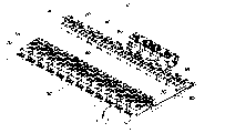
Fig. 1 is the planimetric map according to the fluid distribution panel of one embodiment of the invention;
Fig. 2 is the side view of the fluid distribution panel of Fig. 1;
Fig. 3 is the sectional view along a part of fluid distribution panel of the line 3-3 intercepting of Fig. 2;
Fig. 4 is that the fluid distribution panel of Fig. 1 is by the side view of counter-clockwise half-twist;
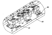
Fig. 5 is the fluid distribution panel of Fig. 1 about 45 ° perspective view that turned clockwise;
Fig. 6 is the fluid distribution panel of Fig. 1 about 135 ° perspective view that turned clockwise;
Fig. 7 is the enlarged perspective of the part of the fluid distribution panel discerned in Fig. 5;
Fig. 8 is the enlarged perspective of the part of the fluid distribution panel discerned in Fig. 6;
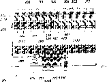
Fig. 9 may be used for forming the many different manifold of fluid distribution panel of Fig. 1 and the perspective view of substrate;
Figure 10 is the enlarged perspective according to the two component position substrate of one aspect of the invention;
Figure 11 is the sectional view of the two component position substrate of Figure 10;
Figure 12 is the enlarged perspective according to the single component position substrate of another aspect of the present invention;
Figure 13 is the sectional view of one component substrate shown in Figure 12;
Figure 14 is the planimetric map according to the fluid distribution panel of another embodiment of the invention;
Figure 15 is the side view of the fluid distribution panel of Figure 14;
Figure 16 is that the fluid distribution panel of Figure 14 is by the side view of counter-clockwise half-twist;
Figure 17 is the fluid distribution panel of Figure 14 about 135 ° perspective view that turned clockwise;
Figure 18 is the enlarged perspective of the part of the fluid distribution panel discerned in Figure 17;
Figure 19 is the fluid distribution panel of Figure 14 about 45 ° perspective view that turned clockwise;
Figure 20 is the enlarged perspective of the part of the fluid distribution panel discerned in Figure 19;
Figure 21 is the enlarged perspective of some different manifolds that possible be used for forming the fluid distribution panel of Figure 14;
Figure 22 may be used for forming the some additional manifold of fluid distribution panel of Figure 14 and the enlarged perspective of single component position substrate;
Figure 23 is the enlarged perspective according to the various substrates of one aspect of the present invention;
Figure 24 may be used for forming the some multicomponent substrates of fluid distribution panel of Figure 14 and the enlarged perspective of substrate insert;
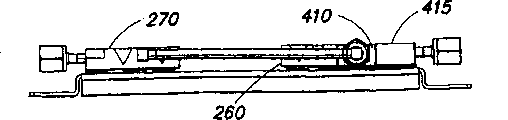
Figure 25 is the partial cut away side views along the fluid distribution panel of Figure 14 of the line 25-25 intercepting of Figure 15;
Figure 26 may be used for the various element of fluid distribution panel is installed to the enlarged view of the automatic location and installation assembly on the mounting plate according to another aspect of the present invention;
Figure 27 is the exploded view from multiple different perspectives of the automatic location and installation assembly of Figure 26; And
Figure 28 is the planimetric map in hole that may be used for holding the automatic location and installation assembly of Figure 26 in mounting plate.
Detailed description of the present invention
This invention is not limited to the structure of element statement in the following description or that enumerate with accompanying drawing and the details of arrangement in its application facet.The embodiment neutralization that the present invention can be embodied in other is put into practice in various mode or is implemented.In addition, wording used herein and term are for purpose of description, should not be counted as restriction." comprise ", " composition " or " having ", " comprising ", " relating to " and change in this article use and mean the project listed thereafter and the project of coordinate and interpolation thereof included.
Fig. 1 illustrates the planimetric map according to the fluid distribution panel of one embodiment of the invention.The fluid distribution panel of giving an example among Fig. 1 can be used for selectively one or more different process fluids being offered common manifold.For example, fluid distribution panel may be used for selectively one or more different process fluids being offered the common manifold that itself may be coupled with the other parts or the fluid treatment instrument fluid of fluid system.
Though mainly just be used for the distribution of the gaseous fluid of semiconductor machining application is described in this present invention, but people should figure out the present invention and not be subjected to such restriction, and can with such as liquid or slurry other process fluid or with the use that combines of gas, liquid or slurry.And the present invention is not limited to semiconductor machining and uses, and uses because it also may be used for chemistry, and pharmacy is used or the like.Therefore, though the present invention describes with reference to the system of the distribution that is provided at the process gas that uses in the semiconductor machining application, people should figure out the present invention and not be subjected to such restriction.
Put it briefly, the fluid distribution panel 100 that Fig. 1 gives an example comprises numerous gas stick A-L, and each all is fit to accept from the process gas of technology source of the gas (showing) and process gas or other gas such as purge gas is offered another part of gas system or handling implement.Each all provides the flow path that extends and comprise numerous ports that form by first direction (in Fig. 1 from top to bottom) in common plane among the gas stick A-L.Various fluid treating device such as valve, purifier, filter, pressure converter, pressure regulator, dehumidifier, mass flow controller (not showing) can be fastened on the port adjacent in each corresponding gas stick and along flow path delivery technology gas or other gas hermetically.First common manifold 110 that comprises numerous ports can be placed in the flow path of each gas stick, to allow using gas stick separately that process gas or other gas such as purge gas are offered second common manifold 120.Second common manifold also comprises numerous ports, and is placed on the flow path end of each gas stick so that one or more process gass or other gas are offered further part in handling implement or the gas system.Because be in line in the common plane of all ports in flow path of the port in each common manifold, so the pneumatic pannel that may obtain highly to be reduced.This is favourable, because the space is very precious in the clean of using such pneumatic pannel often.In addition, the be coupled decreased number of the pneumatic pannel that necessary number of seals separates with different height from substrate and manifold of each flow path and common manifold fluid is got off.In addition, using substrate two places that the port fluid is coupled to the port of manifold of one or more substrates, the realization leak-tight seal essential fastening piece number can be reduced to four fastening pieces, opposite with six above fastening pieces in the traditional design.These and other aspect of the present invention is described in detail now in conjunction with the accompanying drawings.
As shown in Figure 1, pneumatic pannel 100 comprises numerous gas stick A-L, and each gas stick all is installed on the public bottom surface 10.Though do not illustrate specific installation configuration in the accompanying drawings, gas stick can be installed on the public bottom surface 10 from the top, bottom surface or from the below, bottom surface with any method in many well-known methods.Each comprises that all the threaded fastener of common use such as the Allen bolt is fastened to the single component position substrate 60 and the two component position substrate 70 of public bottom surface 10 among the gas stick A-L.Each substrate 60,70 all be usually with one such as 316 stainless steels stainless steel, nickel-base alloy or suitablely use other material to make with calculated fluid.Each substrate 60,70 all has the groove 69,79 (seeing the most clearly) that forms therein so that hold manifold part 20,25,30,35 and 40 in Fig. 9,10,11,12 and 13.Each manifold part 20,25,30,35 and 40 (seeing the most clearly in Fig. 9) also is to make with stainless steel or other suitable material of a block length usually, and is joined together to form common manifold 110,120.For example, in the occasion of making manifold part 20,25,30,35 and 40 with stainless steel, the manifold part may be welded together to form common manifold 110,120 in a conventional manner.In the embodiment that Fig. 1 gives an example, the dual-element substrate 70 of each gas stick A-L accepts to be used for selectively purge gas (providing via conduit 85) being offered the manifold part (for example, the manifold part 35 among the gas stick A) of the flow path of gas stick separately.As shown in Figure 1, each one component substrate 60 also accepts to be used to provide the manifold part (for example, the manifold part 20 of gas stick A) of the public public outlet that can be connected with handling implement or another part 90 of gas handling system of each gas stick A-L.In the embodiment of giving an example, the part 90 of gas handling system is to use by being cited in this with its U. S. Patent of all incorporating into the 6th, 394, and the numerous interconnected negative and positive substrate of describing in 138B1 number forms.
In use, each gas stick A-L is connected on the technology source of the gas by the flange 50 that is fastened on the bottom surface 10 with a pair of fastening piece (not showing).Complementary flange (not showing) is connected to flange 50 usually and provides from the technology source of the gas on the conduit of process gas.As what the most clearly see in Fig. 8, flange 50 comprises and is used for the lateral port 52 that top port 51 that (via the flange of complementation) connect the technology source of the gas is connected with suction port 71 with the top port 51 of flange 50 and substrate 70.Process gas flows to the relief opening 72 (Figure 10,11) that forms by the fluid passage (for example, seeing Figure 11) of substrate 70 inside in the end face of substrate 70.Twoway valves or other fluid treatment element (show) are placed on relief opening 72 and above the suction port 73 that also forms in the end face of substrate 70, and seal with substrate 70 formation.The sealing component of metallic gasket or other type (not showing) is commonly used to provide leak-tight seal around other port in port 72,73 and substrate 70 end faces.For example, in the embodiment that Fig. 1 describes, each port that forms in the substrate end face (and the port that forms in manifold part) all comprises the counter sink (unnumbered, but show) of the C shape Sealing that is fit to accept annular in Fig. 9,10,11,12 and 13.As an alternative, the lip ring of other type is (for example, by being cited in the U. S. Patent the 5th that this all incorporates them into, 803, those that describe in No. the 6th, 142,539, No. 507 and the U. S. Patent) can in substrate and manifold part, suitably be used under the situation of configured port.In described embodiment, Twoway valves allows process gas further to flow along gas stick selectively.
Then, process gas flows to the relief opening 74 that also forms from suction port 73 by the V-shaped groove (as shown in figure 11) that forms in the end face of substrate 70 the main body of substrate 70.Substrate 70 comprises the groove 79 that is used for accepting common manifold part 110.For example, in the embodiment that Fig. 1 enumerates, the substrate of gas stick A 70 accepts to have two dibit manifold parts 35 at port 37,39 (Fig. 9) that the end face of manifold part 35 forms and another port 36 of forming in the surface of crosscut end face on manifold part 35.The port 36 that in the lateral surfaces of manifold part 35, forms by fluid be connected to another manifold part (for example, the manifold part 40 among Fig. 1 and 9), form common manifold part 110 together.Groove 79 in the substrate 70 is fit to place like this manifold parts 35, so that one of port 37,39 that forms in the end face of manifold part 35 is in line with relief opening 74 with at the suction port 76 of the another side of the groove 79 of substrate 70 in the common plane of the end face of substrate 70.As what describe in further detail below, each can comprise groove and manifold part being used for making form the device that one of port 74,76 and port in the end face of manifold part 35 (for example, 37,39) are in line in the end face of substrate 70.
In the embodiment of enumerating, three-way valve (not enumerated) is placed on the top of one of port 37,39 in the end face of port 74 in the substrate 70 and 76 manifold parts 35 and is fastened on the substrate 70 with numerous fastening pieces (showing).Numerous fastening pieces is received in the hole in the end face of the substrate 70 that comprises at least one hole (preferred two holes) on each side of groove 79 of substrate 70.Advantageously, for the inclusion seal that forms valve only needs four fastening pieces (two on every limit, groove 79 both sides), yet in traditional design, each port needs two fastening pieces traditionally, in order to realize that the inclusion seal of three ports is needed six fastening pieces altogether.Fastening piece of including on groove 79 every limits and gasket (not showing) or other closure member are formed on the end face port 37 of substrate port 74,76 and manifold part 35 or 39 inclusion seal together.Three-way valve allows to provide with the process gas of common manifold 110 transmission or other gas (seeing Figure 11) such as purge gas with the V-shaped groove of suction port 76 in the connection substrate 70 and the relief opening 78 in the substrate 70.In the embodiment of enumerating, the suction port of mass flow controller (show) by fluid be connected on the relief opening 78 in the substrate 70 and process gas or other gas offered the suction port 61 of single component position substrate 60 via the relief opening of mass flow controller.Mass flow controller bridge joint substrate 70 and substrate 60.
As what clearly enumerate in Figure 12 and 13, single component position substrate 60 comprises the suction port 61 and the relief opening 62 that couple together with the V-arrangement passage that forms in the end face of substrate 60.At least one counter sink (preferred two counter sinks) is to form in the end face of substrate 60, so that the relief opening of mass flow controller is fastened to hermetically on the suction port 61 of substrate 60.
In the embodiment of enumerating, Twoway valves (not enumerated) is placed on the port 62 of substrate 60 and is fastened on the substrate 60 above the port in the end face of manifold part 20 22 and with numerous fastening piece (not showing).Groove 69 both sides that numerous fastening pieces is received in substrate 60 respectively comprise the counter sink on the end face of substrate 60 of at least one counter sink (preferred two counter sinks).Include the fastening piece on groove 69 both sides and sealing gasket (showing) or other sealing component in and form inclusion seal at the port 22 of the end face of the port 62 of substrate 60 and manifold part 20 together.Twoway valves permits process gas or other gas such as purge gas are offered common manifold 120, again another part from the common manifold to the system 90.
Fig. 9 illustrates many manifold parts 20,25,30,35 and 40 of the pneumatic pannel that can be used for forming according to one embodiment of the invention.Manifold part 20,25,30,35 and 40 is that similar each comprises that all the manifold bodies made with long piece and each all comprise port that at least one forms and the port that at least one forms in the manifold bodies end face in the manifold bodies surface of crosscut manifold bodies end face.In addition, each manifold part all comprises the device that is used for making one or more ports that form and the one or more ports that form to be in line in the end face of substrate 60,70 in the manifold bodies end face.In the embodiment of enumerating, each manifold part all is included in a pair of groove that forms in the lateral surfaces of manifold bodies, and they are being spaced on the both sides of port and are being used to make port on the manifold bodies end face and the one or more ports in the substrate are in line on the lateral surfaces.People should figure out as the people who is familiar with this technology known have only a groove and positioning device thereof (for example, by being cited in those that enumerate among No. 1, the laid-open U.S. Patents application 2002/0000256A that this all incorporates it into) and can be used by yes-no decision ground.
As shown in Figure 9, manifold part 20 is included in single-port 22 that forms in the end face of manifold bodies and a pair of port 21,23 that forms in the opposed manifold bodies surface of crosscut manifold bodies end face.Fluid passage along the inside that the longitudinal axis of manifold bodies forms couples together end face port 22 and each port that forms 21,23 in lateral surfaces.
Manifold part 25 is similar to manifold part 20, yet manifold part 25 only is included in the single-port 26 that forms in the lateral surfaces of manifold bodies.Manifold part 25 is used to stop by the contiguous manifold utility fluid manifold that is interconnected to form 110,120 partly usually.
Manifold part 30 is similar to manifold part 20, and it is included in a pair of port 31,33 that forms in the opposed lateral surfaces of manifold bodies.Yet manifold part 30 is included in two ports 32,34 that form in the manifold bodies end face.Each port 31,32,33 and 34 all is communicated with the internal fluid channels that forms along the manifold bodies longitudinal axis in manifold bodies.Each port that forms in the manifold end face 32,34 is all surrounded by the numerous locating slots that form on the manifold bodies both sides.Manifold part 30 can be used for the flow path segment fluid flow of first gas stick and second gas stick therefore be connected to that another manifold is partly gone up and be connected on the common manifold 110,120.
Another manifold part 35 is included in a pair of port 37,39 that forms in the end face of manifold bodies and the single-port 36 that forms in the lateral surfaces of manifold bodies.Manifold part 35 is similar to manifold 25, and it can be used for stopping common manifold 110,120.Yet manifold part 35 is used to the fluid flow path of two gas stick partly is connected on the common manifold 110,120, and for example, Fig. 1 is cited.
Manifold part comprises that also three manifold parts 40, the latter are included in 43 and a pair of port 47,49 that forms in the opposed lateral surfaces of crosscut end face of three ports 41,42 of forming in the manifold bodies end face on manifold bodies.Each side surface of manifold part 40 is included in can being used for of adjoining on each side surface of manifold bodies that each port 41,42 and 43 forms and makes numerous in groove that the port of manifold part 40 and the port of substrate separately be in line.
People should figure out, though some different manifold parts 20,25,30,25 and 40 have been described at this, the present invention is not limited to the embodiment of enumerating.For example, may use forming four or more port on the manifold bodies end face and have only the manifold part that forms two ports in single-port or the opposed lateral surfaces in the lateral surfaces in manifold bodies in manifold bodies.People should further figure out, though being listed as, the port that forms comprises the counter sink that is fit to accept annular C type Sealing in manifold part end face, but different port configurations can be used by such yes-no decision ground, so that the fluid treatment element of standard can use with it.And the port that does not need all to form in the manifold end face has the sealing configuration of same type, because one type sealing may be used to a port, and the sealing of another kind of type may be used to another port.
Shown in Fig. 9,10,11,12 and 13, the locating slot that can be used for making manifold partly be positioned at groove 69,79 the insides of substrate also may be to form in the side surface of each groove in substrate 60 and 70.In use, the manifold part is inserted groove 69,79 like this, so that the locating slot with in the manifold part in the substrate 60,70 aligns approx, then positioning dowel 67,77 is inserted every pair of locating slot from the top, and manifold is accurately located in groove 69,79. Positioning dowel 67,77 can be made with any suitable material, but preferably uses the material that the process fluid in usefulness is inertia to make, so that just in case any leakage takes place, the linear array of groove the inside manifold part can be not destroyed.
Each positioning dowel 67,77 has such length, so that when positioning dowel inserts groove on substrate and the manifold part,, the end face of positioning dowel do not avoid interference sealing between the port of substrate and manifold and fastening flow element thereon thereby not being higher than the end face of substrate and manifold part.Though accompanying drawing showed, among the groove of groove side surface may extend to the bottom surface of groove 69,79, so that positioning dowel may be longer than the degree of depth of groove aspect length, and still remain on below the substrate end face when inserting fully.
Shown in Figure 11 and 13, at it, each substrate 60,70 can be included in the hole 65,75 that can be used for removing it after the manifold part has been inserted into groove that forms in the bottom surface of groove.For example, the rigid member such as screw-driver can insert and be used to manifold part and releases from groove below substrate.As an alternative, the hole 65,75 in trench bottom surfaces may be threaded, so that threaded member patchhole 65,75 incrementally, removes the manifold part.
As what show among Figure 10,11 and 12, one of port in substrate 60,70 end faces can be included in the leak port 95 that forms in the substrate end face at least.Usually, leak port 95 be with every pair of port that flow element fluid ground is connected between provide.
In embodiment described herein, each common manifold 110,120 all by fluid be connected to another part 90 of gas handling system.People should figure out the present invention and be not limited to this configuration of enumerating.For example, common manifold 110 may change into by flange 50 fluids be directly connected on another source of the gas.And, though each substrate 60,70 all is depicted as single groove 69,79 and forms therein, but may provide multiple groove as an alternative, so that various fluid can be introduced to each gas stick among the gas stick A-L, or is introduced to the one or more gas stick among all gas stick as an alternative.In addition, though people should figure out that customized configuration that use Twoway valves, three-way valve and mass flow controller are used among each gas stick A-L is described, the present invention is not subjected to such restriction.Therefore, according to instruction of the present invention, can on single substrate, provide two above element stations.For example, the additional element station of one or more various other fluid treatment elements that are fit to accept filter, pressure transducer or pressure regulator or provide as usual can be provided substrate 70.The different elements combination of countless versions in addition, do not require that the flow element that is installed on each substrate is the same in each gas stick, because may be to imagine easily.
In addition, though the present invention is mainly according to utilizing countersunk head pass sealed fluid flow processing element to be described, but people should figure out, also may use the fluid treatment element of other type, for example, surface installation type element, tube mount type element, or the like, so that this pneumatic pannel can adapt to the element of commercially availabie and/or standard miscellaneous.In addition, though show as yet and be used for customized configuration that substrate 60,70 is installed on the bottom surface 10, it is operable that people should figure out many kinds of installation methods.
Figure 14-28 illustrates the fluid distribution panel according to another embodiment of the invention.The same with the front in conjunction with the embodiment that Fig. 1-13 describes, the embodiment of Figure 14-28 allow the port that in the substrate end face, forms in common plane and in the common manifold end face or the port that forms in some part of common manifold be in line.For this purpose, many substrates are included in the groove that can accept the manifold part that forms in the substrate end face.Yet, the embodiment of Figure 14-28 uses different devices that the port in substrate and the manifold part is in line, rather than use and positioning dowel (for example, the positioning dowel 67 and 77 among Fig. 9-13) in the groove fit of the side formation of groove and manifold part.For example, as shown in figure 22, complementary locating column 281 and positioning hole 282 can provide in the bottom surface of groove and the bottom surface of manifold part, so that port in the manifold part end face and the one or more port in the substrate end face are in line.Locating column may form in trench bottom surfaces, and positioning hole is to form in the bottom surface of manifold part as shown in the figure, or as an alternative, locating column may be to form in the bottom surface of manifold part, and positioning hole forms in trench bottom surfaces.
Another difference between the embodiment of the embodiment of Fig. 1-13 and Figure 14-28 is that the embodiment of Figure 14-28 uses machanical fastener that the end face of manifold part and substrate is fixed within the common plane, rather than utilizes the installation of the gas treatment element of valve or filter and so on to fix the location of port in common plane.As what describe in further detail below, by manifold part being installed in rigidly the groove the inside of substrate, the leakage that impact or vibration cause that becomes in fact of formed fluid path more has immunity.
Further difference is in the embodiment of Figure 14-28 between the embodiment of the embodiment of Fig. 1-13 and Figure 14-28, and each component substrate (and other element) flexibly is installed to can be rigidly attached on the mounting plate on the panel bottom surface.Specifically, unsteady base be used for making various element be attached to allowance in the limited motion on the direction of three quadratures, important stretching and the thermal release between shear strength, realization element and mounting plate and the bottom surface (permit element whereby and heated effectively or cool off, and do not need at first to heat or cool off the bottom surface thermal mass) be provided and provide on the mounting plate of vibration damping.These and other aspect of the embodiment of Figure 14-28 will give detailed description now below.
The fluid distribution panel 200 that Figure 14 enumerates comprises numerous gas stick A-L, and each all is fit to accept from the process gas of technology source of the gas (showing) and process gas and/or the another kind of gas such as purge gas is offered the another part or the handling implement of gas system.Each gas stick A-L provides the flow path that extends by first direction (in Figure 14 from top to bottom) and is included in the numerous ports that form in the common plane.Various fluid treating devices such as valve, purifier, filter, pressure transducer, dehumidifier, mass flow controller (not showing) are fastened on the port adjacent in each corresponding gas stick and along flow path hermetically transmits process gas or other gas.First common manifold 2110 that comprises numerous ports is placed on numerous gas stick and (that is, gas stick A-F in) the flow path, to allow each gas stick process gas or the another kind of gas such as purge gas is offered second common manifold 2120.Second common manifold 2120 also comprises numerous ports, and be placed on the flow path end of each gas stick A-E, so that one or more process gass or other gas are offered the further part (for example, mixed substrates 410) of handling implement or gas system.The 3rd common manifold 2130 that comprises numerous ports is to offer the further part (for example, mixed substrates 410) of handling implement or gas system from the process gas of one or more gas stick H-L with the combination of those process gass or process gas and locate for accepting.The same with the front in conjunction with the fluid distribution panel that Fig. 1 describes, because the port of each common manifold is in line in the common plane of port in flow path, so can obtain the highly pneumatic pannel of minimizing.
As shown in figure 14, pneumatic pannel 200 comprises the numerous excellent A-L of gas.Opposite with the fluid distribution panel of describing among Fig. 1, not that each gas stick (for example is directly installed on public bottom surface rigidly, bottom surface 10 among Fig. 1) on, but each the gas stick A-L among Figure 14 is to use the unsteady base (describing in further detail below in conjunction with Figure 26 and 27) of itself being installed on bottom surface (not showing) or other rigid construction flexibly to be installed on the mounting plate 210.In the embodiment that Figure 14 describes, mounting plate 210 can be made in order to the tinsel of Figure 15 and 16 illustrational mode bendings.As what below will describe in further detail, mounting plate 210 has the thermal mass than bottom surface 10 much less of Fig. 1, (see Figure 15, heating for example) or cooling stick heat or cooling to the one or more gas stick among the gas stick A-L with effective and efficient manner consequently can to insert the hole 500 of passing the gas stick extension that forms substrate by use.For further hot separation gas rod, as an alternative, mounting plate 210 can be made with rigid material (for example, plastics) adiabatic rather than heat conduction.
Each gas stick A-E comprises that the threaded fastening piece of common usefulness (for example, Allen bolt) flexibly is fastened to single component position substrate 260 and the two component position substrate 270 on the mounting plate 210.Each substrate 260,270 normally uses a stainless steel (for example, 316 stainless steels), nickel-base alloy or suitable other material that uses with calculated fluid to make.Each substrate 260,270 all has the groove 269,279 (seeing the most clearly in Figure 22 and 23) that forms therein to accept manifold part 220,225,230,235,240,255 and 265 (seeing the most clearly) in Figure 21 and 22.Each manifold part 220,225,230,235,240,255 and 265 usually also be make with the stainless steel of a block length or other suitable material and also be joined together to form common manifold 2110,2120 and 2130.For example, under the situation of making the manifold part with stainless steel, the manifold part can be soldered to together by butt joint in a conventional manner, forms common manifold 2110,2120 and 2130.
In the embodiment that Figure 14 enumerates, the two component position substrate 270 of each gas stick A-F accepts to be used for selectively purge gas (providing from purge gas inlet 201 via conduit 285 and substrate insert 435A) being offered the manifold part (for example, the manifold part 220 of gas stick A) of the flow path of corresponding gas stick.Each single component position substrate 260 also accept to be used to provide for each gas stick A-E be public and also the manifold part of the public outlet that can be connected with another part of handling implement or gas handling system (for example, the manifold part 235 of gas stick A), as shown in figure 14.In the embodiment of enumerating, one or more process gass or purge gas are to offer via the substrate insert 420 of turning left that is connected with common manifold 2120 fluid ground earlier to mix inlet substrate 410, then via another insert 435B to mixed export substrate 415, arrive relief opening 202 again.
Other process gas can be that the inlet 203 via gas stick G-L receives, and offers other the single component position substrate 260 that is connected with common manifold 2130 fluid ground via single component position substrate 405 (it does not comprise groove) then.Usually will be used for accepting the process gas that does not need to utilize purge gas of inertia, nontoxic and/or non-activity in the single component position substrate 405 of gas stick G-L illustrated.As shown in the figure, offer via the substrate insert 425 of turning right from the process gas of one or more gas stick G-L and to mix inlet substrate 410, then via another insert 435C to mixing platform outlet substrate 415, arrive relief opening 202 then.
In use, each gas stick A-L is connected with the technology source of the gas by suction port mouth 203, and in the embodiment of enumerating, this being connected to is threaded.With regard to gas stick A-F, process gas flows to suction port 271 (for example, seeing Figure 23), then by the internal fluid channels in the substrate 270 to the relief opening 272 that in the end face of substrate 270, forms.Twoway valves or other fluid treatment element (show) are placed on relief opening 272 and above the suction port 273 that also forms in the end face of substrate 270, and seal with substrate 270 formation.The sealing component of metallic gasket or other type (not showing) is used to provide inclusion seal around other port in the end face of port 272,273 and substrate 270 usually.The embodiment of describing with Fig. 1 is the same, and each port that forms in substrate 270 end faces (and the port that forms in the manifold part) can comprise the counter sink that is fit to accept annular C type Sealing.As an alternative, the ring packing of other type (for example, at U. S. Patent the 5th, 803, those that describe in No. the 6th, 142,539, No. 507 and the U. S. Patent) can with in substrate and manifold part suitably the port of configuration use.In described embodiment, Twoway valves allows process gas further to flow along gas stick A-F selectively.
Then, process gas flows to the relief opening 274 that also forms from suction port 273 through the V-shaped groove (showing) that forms in the end face of substrate 270 in Figure 23 the main body of substrate 270.Substrate 270 comprises the groove 279 that is used for accepting common manifold part 2110.For example, in the embodiment that Figure 14 enumerates, the substrate 270 of gas stick A accepts to have the unit manifold part 220 of single-port 222 (Figure 21) that forms and a pair of port 221,223 that forms on the counter surface of crosscut end face on the manifold part 220 in the end face of manifold part 220.The port 221,223 that in the lateral surfaces of manifold part 220, forms by fluid be connected to conduit 285 and another manifold part (for example, the manifold part 240 among Figure 14 and 23), form common manifold part 2110 together.Groove 279 in the substrate 270 is fit to place like this manifold parts 220, so that the port 222 that forms in end face is in line with relief opening 274 and at the suction port 276 of the another side of the groove 279 of substrate 270 in the common plane of the end face of substrate 270.
The two component position substrate 70 that is used to the linear array of fixed port in common plane with gas treatment element or the Unit Installation such as valve or filter is opposite, and two component position substrate 270 uses a pair of fastening piece 205 that is arranged in groove 279 both sides that the manifold part is installed in substrate trenches 279 the insides rigidly.Each fastening piece 205 is received in the installation depression 290 that forms in the trenched side-wall, as shown in figure 23.Depression 290 is installed outwards is arc usually in shape, terminate in interior threaded hole 291, and comprise support or edge 292.The edge 292 that depression 290 is installed works to stop the bottom margin (being similar to the structure of fastening piece shown in Figure 26 315) of fastening piece 205 heads.Each manifold part 220,225,230,240,255 and 265 comprises such complimentary recess 295 (seeing Figure 21 and 22), so that when fastening piece 205 was inserted into, the bottom margin of fastening piece 205 heads forced manifold closely to prop up the bottom of the groove 279 of substrate 270.In general, each installs depression 290 spans greater than 180 degree, and complimentary recess 295 spans in the manifold part are less than 180 degree.During the location, depression 290,295 forms complete in fact circle.The highest part of fastening piece 205 and the degree of depth at edge 292 are to determine size like this, so that the highest part of fastening piece 205 does not protrude and do not disturb sealing from the end face of substrate 270.In general, a pair of fastening piece 205 that is positioned at groove 279 opposed side surfaces is enough to force the manifold part closely to be fixed on groove 279 the insides of substrate 270.
In the embodiment of enumerating, three-way valve (show) is placed on the top of port 274,276 on the substrate 270 and the port 222 on manifold part 220 end faces usually and is fastened on the substrate 270 by numerous fastening pieces (showing).Numerous fastening pieces is received in the counter sink of substrate 270 end faces, is included at least one counter sink on groove 279 every limits of substrate 270, preferred two counter sinks.Fastening piece that groove 279 every edge joints are subjected to sealing gasket (showing) or other sealing component in substrate port 274,276 and the port 222 in the end face of manifold part 220 among form inclusion seal.The V-shaped groove (seeing Figure 23) that three-way valve allows the suction port in the substrate 270 276 to be connected to the relief opening 278 in the substrate 270 provides with the process gas of common manifold 2110 guiding or the another kind of gas such as purge gas.In the embodiment of enumerating, the suction port of mass flow controller (show) usually by fluid be connected to the relief opening 278 of substrate 270 and process gas or other gas offered the suction port 261 of single component position substrate 260 (Figure 23) via the relief opening of mass flow controller.Mass flow controller is with substrate 270 and substrate 260 among each gas stick A-E of bridge joint.
With regard to gas stick G-L, 203 process gass of receiving flow to the suction port 406 (seeing Figure 23) of single component position substrate 405 in the gas access, and the internal fluid channels in the process substrate 405 is to the relief opening 407 that forms in the end face of substrate 405.Twoway valves or other fluid treatment element (show) are placed on relief opening 405 and above the suction port 408 that also forms usually in the end face of substrate 405, and form with substrate 405 and to seal.Other port that the sealing component of metallic gasket or other type (showing) can be used in port 407,408 and substrate 405 end faces provides inclusion seal on every side.Each port 407,408 and 409 that forms in the end face of substrate 405 can comprise the counter sink that is fit to accept annular C type Sealing, substitutes the lip ring that uses other type though can be used as.Twoway valves allows process gas further to flow along gas stick G-L selectively.Single component position substrate 405 does not comprise groove (for example, groove 269), and do not need to accept the process gas that purifies as noticing that before that works and being used for.
Then, flow through the V-shaped groove that in the main body of substrate 405 (Figure 23), forms to the relief opening 409 that also in the end face of substrate 405, forms from suction port 408 process gass of substrate 405.With regard to each gas stick H-L, the suction port of mass flow controller (show) usually by fluid be connected to the relief opening 409 in the substrate 405 and process gas offered the suction port 261 (Figure 23) of single component position substrate 260 via the relief opening of mass flow controller.The substrate 405 of each gas stick G-L of mass flow controller bridge joint and substrate 260.
As the most illustrational in Figure 22 and 23, single component position substrate 260 is included in channel attached suction port 261 of V-arrangement and the relief opening 262 with inside that forms in the end face of substrate 260.For the relief opening of mass flow controller being fastened to hermetically on the suction port 261 of substrate 260, in the end face of substrate 260, form at least one counter sink and preferred two counter sinks.
With utilize gas treatment element or the Unit Installation such as valve or filter opposite the single component position substrate 60 that the linear array of port is fixed in the common plane, single component position substrate 260 uses a pair of fastening piece 205 that is arranged in groove 269 both sides manifold partly to be installed in rigidly groove 269 the insides of substrate 260.In this respect, single component position substrate 260 is similar to two component position substrate 270, caves in 290 because all be received in the installation that forms in the sidewall of groove 269 as each fastening piece 205 in Figure 23 illustrated.Depression 290 is installed in interior threaded hole 291, stops, and comprised the support or the edge 292 of the bottom margin that stops fastening piece 205 heads.Each manifold part 220,225,230,240,255 and 265 comprises complementary depression 295 (seeing Figure 21 and 22), so that when inserting fastening piece 205, the bottom margin of fastening piece 205 heads forces manifold partly closely to prop up the bottom surface of the groove 269 of substrate 260.The highest part of fastening piece 205 and the degree of depth at edge 292 are to determine size like this, and the highest part of part quilt so that fastening piece 205 does not exceed the end face of substrate 260 and disturbs sealing.To place substrate 270 the same with dual-element, and a pair of fastening piece 205 that is positioned at groove 269 opposed side surfaces is enough to force manifold partly closely in groove 269 the insides of substrate 260.
In the embodiment of enumerating, Twoway valves (show) is placed on above the port (for example, port 239) in the end face of port 262 in the substrate 260 and manifold part (for example the manifold part 235) and by numerous fastening piece (showing) and is fastened on the substrate 260.The both sides that numerous fastening pieces is received in groove 269 in the substrate 260 respectively comprise the counter sink in the end face of substrate 260 of at least one counter sink (preferred two counter sinks).The fastening piece of including on groove 269 every limits forms inclusion seal together with sealing gasket (not showing) or other closure member at the port 262 of substrate 260 and the port of manifold part end face.Twoway valves allows process gas or the another kind of gas such as purge gas are offered common manifold 2120, again the another part from the common manifold to the system.
The same with H-L some element of sharing of gas stick F with G and gas stick A-E, but how the element that illustrates other may be used for producing the fuid distribution system that can adapt to configuration miscellaneous.For example, gas stick F comprises two component position substrate 270, a component position T-slot substrate 430 and the substrate insert 420 of turning left.Two component position substrate 270 271 is accepted to offer the relief opening 272 that forms from the process gas of technology source of the gas and process gas via the fluid passage of inside in the end face of substrate 270 in the gas access.Twoway valves or other fluid treatment element (show) are placed on relief opening 272 and above the suction port 273 that also forms in the end face of substrate 270, and seal with substrate 270 formation.Then, flow through the V-shaped groove (in Figure 23, showing) that in the main body of substrate 270, forms to the relief opening 274 that also in the end face of substrate 270, forms from the process gas of suction port 273.Substrate 270 comprises the groove 279 that is used for accepting manifold part 2110.For example, in the embodiment that Figure 14 enumerates, the substrate of gas stick F 270 accepts that a pair of port that forms 237,239 (Figure 21) is arranged and the dibit manifold part 235 of the single-port 236 that forms in the surface of crosscut end face in manifold part 235 in end face.The groove 279 of substrate 270 is fit to place like this manifold parts 235, so that the port 237 that forms in end face is in line with relief opening 274 with at the suction port 276 of groove 279 another sides of substrate 270 in the common plane of the end face of substrate 270.
Three-way valve (show) is placed on usually above the end face port 237 of the port 274,276 of substrate 270 and manifold part 235 and by numerous fastening piece (showing) and is fastened on the substrate 270.Among the end face port 237 of the port 274,276 of substrate and manifold part 235, form inclusion seal together with sealing gasket (showing) or other closure member at fastening piece that groove 279 every edge joints are subjected to.Three-way valve allows to provide with one of the process gas of common manifold 2110 guiding or the another kind of gas such as purge gas by the V-shaped groove (seeing Figure 23) of the relief opening 278 that the suction port in the substrate 270 276 is connected to substrate 270.The suction port of mass flow controller (show) by fluid be connected to the relief opening 278 of substrate 270, and process gas or other gas are offered the suction port 431 (Figure 23) of single component position T-slot substrate 430 via the relief opening of mass flow controller.Mass flow controller is bridge joint substrate 270 and T-slot substrate 430 in gas stick F.
Gas stick F use to be fit to accepts the single component position T-slot substrate 430 of the substrate insert 420,425 (Figure 24) of turning left or turning right, rather than uses single component position substrate 260 with the same in each gas stick A-E and H-L.T-slot substrate 430 is included in suction port 431 and the relief opening 432 that forms in its end face and constructs the groove 269 that is similar to single component position substrate 260.Yet T-slot substrate 430 also is included in the additional trenches 283 that the substrate insert 420,425 of turning left or turning right is accepted in the permission that forms in the end face of substrate 430.
Each substrate of turning left or turning right inserts 420,425 and comprise a pair of port (422,423 and 427,428) with the V-shaped groove connection that forms in its end face.Each substrate insert of turning left or turning right 420,425 (Figure 24) also is included in the port 421,426 that forms in the surface of crosscut end face in the substrate insert.Port 421,426 in inside by fluid be connected to V-shaped groove and therefore to each port 422,423 and 427,428, and may be used for connecting the manifold that is connected with common manifold 2120 or 2130 fluid ground partly (for example, the manifold part 240 of Figure 14).In the illustrational embodiment of Figure 14, Twoway valves (show) can be placed on above the port 432 of substrate 430 like this and substrate inserts above 420,425 the port 422,427 so that the port 423,428 that one or more process gass or purge gas from one or more gas stick A-F and G-L are offered substrate insert 420,425 selectively, then from there to mixing inlet substrate 410.Usually, three-way valve is placed on that substrate inserts above 420,425 the port 423,428 and mixes inlet substrate 410 or mixed export substrate 415 so that via insert 435B and 435C process gas is offered.
Figure 21 and 22 illustrates many manifold parts 220,225,230,235,240,255 and 265 of the pneumatic pannel that can be used for forming according to embodiment of the present invention.Manifold part 220,225,230,235,240,255 and 265 is similar to the front in conjunction with those of the description of Fig. 9, wherein each all comprises the manifold bodies made from the stainless steel or other the suitable material of a block length, and each all comprises the port that at least one forms in the manifold bodies end face.In addition, each manifold part all comprises the port of another manifold part of at least one connection that forms in the surface of crosscut end face.Because manifold part 220,225,230,235,240,255 and 265 is similar to the front describes in conjunction with Fig. 9 those in fact, so below will only describe its difference in detail.
Shown in Figure 21 and 22, each manifold part 220,225,230,235,240,255 and 265 comprises at least one (preferably a pair of) form and depression 295 that separated each other in manifold part lateral side surfaces.It is outside arc and form not enough half circle (that is, span is less than 180 degree) that each depression all is in shape.Preferably, for each port that forms in the manifold bodies end face, a pair of depression 295 forms on each manifold bodies side surface, and each depression equidistantly separates with port.Under the situation of manifold bodies symmetry (for example, manifold part 220,240, or the like), people should figure out, and can provide less several to depression, and for example, a pair of depression is arranged on each opposite side surfaces of manifold bodies.Each depression 295 296 termination at the edge.Show the most clearly that as Figure 18 and 20 each depression all is formation in order to accept the manifold part is locked in the fastening piece 205 of groove 269,279 the insides of substrate 260,270 rigidly.Depression 295 edge 296 works to stop the bottom margin of the head of (similar to fastening piece 315 shown in Figure 26 aspect structure) fastening piece 205, and when inserting fastening piece 205, the bottom margin of the head of fastening piece 205 forces manifold closely to prop up the bottom surface of the groove 269,279 of substrate 260,270.The degree of depth of the highest part of fastening piece 205 and depression 295 is to determine size like this, so that the highest part of fastening piece 205 does not exceed the end face of substrate 260,270 and do not disturb sealing.In general, a pair of fastening piece 205 that is positioned at the port both sides on the opposite side surfaces of manifold part is enough to force the manifold part to be contained in groove 269,279 the insides of substrate 260,270 tightly.As above-mentioned, each substrate 260,270 all comprises complementary installation depression 290, so that when the manifold part was located in the bottom surface of groove 269,279, depression 290 and 295 formed a common circular hole.
The people who is familiar with this technology should figure out, and uses 205 of the fastening pieces of describing like this to prevent the port of the port at substrate, manifold part and adheres to the possibility of leaking between the fluid treating device on it from above.In particular, firmly prop up the bottom of the groove 269,279 in the substrate 260,270 by forcing the manifold part, manifold is partly reinstated an effect of other substrate 260,270 definition linear array.If the manifold part is fixed in the groove 269,279 of substrate 260,270 built on the sand, so violent impact or vibration are via the further compression seal pad (being placed on the deformable metallic gasket between the port of fluid treating device and substrate and manifold part often usually) of vertical motion in groove of manifold part (thickness of manifold part may less than groove depth), in case that impact or vibration force are removed, it is possible that Sealing itself may leak.
Manifold part 220,225,230,235,240,255 and 265 and those branch pipe part of describing in conjunction with Fig. 9 of front another difference between dividing be the lower surface that positioning hole 282 appears at the manifold part.As what can be clear that in Figure 22, each manifold part may comprise one or more positioning holes 282 in order to constitute with complementary positioning dowel 281 pairings that form in the bottom surface of the groove 269,279 of substrate 260,270.Positioning dowel 281 can be to make with the dowel pins that can enter to press fit the suitable hole that gets out in the bottom surface of groove 269,279.By using the dowel pins of press fit, be processed into instinct and reduced significantly, and dowel pins can be bought by correct size.
Preferably, each branch pipe part branch comprises that the center is arranged in two positioning holes 282 that are located at the both sides of each port that forms in the end face of manifold part in the manifold bottom surface partly.In the embodiment of enumerating, these positioning holes 282 are aimed at the depression 295 in the manifold side surface partly usually.People should figure out, and may replace provides positioning dowel 281, rather than the positioning hole 282 of formation is arranged in manifold part lower surface, and positioning hole 282 is to provide in the bottom surface of the groove 269,279 of substrate 260,270.People also should figure out, no matter where positioning dowel 281 and positioning hole 282 form, positioning dowel 281 all should be shorter than positioning hole on length, so that the lower surface of manifold part overlaps with the bottom surface of groove.
Though described some different manifold parts 220,225,230,235,240,255 and 265 at this, people should figure out the present invention and be not limited to the embodiment of enumerating.For example, may use the manifold part of the port that on the manifold bodies end face, forms of different numbers, and have only single port, or have two ports in the opposed lateral surfaces of manifold bodies, to form in the lateral surfaces of manifold bodies.People should further figure out, though the port that forms in the end face of manifold part is illustrated as the counter sink that comprises the C type Sealing that is fit to the acceptance ring, but different port arrangement may be used as an alternative, so that the standard flow processing element can use with them.In addition, do not require that all ports that form all have the seal arrangement of same type in the end face of manifold, when one type sealing can be used to a port, the sealing of another kind of type may be used in another port.
Shown in Figure 23 and 24, one of port in the end face of substrate 260,270,405,410,420,425,430 can be included in the leak port 95 that forms in the end face of substrate at least.Usually, leak port 95 be will with every pair of port that flow element fluid ground is connected between provide.And, though each substrate 260,270 is depicted as the single groove 269,279 that forms therein, provide multiple groove but can change into, consequently various fluid can be drawn towards each gas stick A-L, or guides one or more gas stick as an alternative into.In addition, people should figure out, though described the customized configuration of using Twoway valves, three-way valve and mass flow controller in each gas stick A-L, the present invention is not subjected to such restriction.Therefore, according to instruction of the present invention, can on single substrate, provide two above element stations.For example, substrate 260,270 may comprise one or more filters that are fit to accept, pressure transducer or pressure regulator or other the add ons station of fluid treatment element of all kinds that provides as usual.And, do not require that the flow element that is installed on each substrate all is the same in each gas stick, because the different elements combination of countless versions may be easy to imagine.
According to another aspect of the present invention, the unsteady base of the embodiment utilization of Figure 14-28 flexibly is installed to substrate and other element on the mounting plate that is subsequently attached on the bottom surface, rather than substrate directly is installed on the bottom surface.The base that floats allows in the limited motion of the direction of three quadratures, so that the substrate of fuid distribution system, manifold part and other parts may be interconnected easily, and does not need accurately extreme in the layout of mounting plate mesopore.Unsteady base also makes the thermal coupling of element disengaging and mounting plate and bottom surface, allows whereby to heat effectively to element or cool off with conventional art.In addition, unsteady base also makes fuid distribution system impact and vibration become more insensitive, and important stretching and shear strength also is provided.In conjunction with Figure 14,18,20,23,24,25,26,27 and 28 this aspect of the present invention is described emphatically now.
Shown in Figure 23 and 24, various substrate 260,270,405,410,415 and 430 each may comprise that all numerous can being used for flexibly is installed to mounting hole or through hole 263 on the mounting plate 210 to substrate.Each all accepts threaded fastener 315 these mounting holes 263, for example the Allen bolt.Each mounting hole 263 is all promising accepts the bottom of head of fastening piece 315 or the concave edges 316 of substrate being pushed to mounting plate 210 (Figure 26) when fastening piece is bonded in the unsteady base 300 that lower limb constitutes.The degree of depth at edge 316 is such, so that when fastening piece 315 engaged with unsteady base 300, the highest part of fastening piece was below the substrate end face, as shown in figure 26.The edge of mounting plate is crooked like this, so that the zone of installation fluid distributing element promotes from the accompanying bottom surface of mounting plate in the mounting plate, as shown in figure 25.
Threaded fastener 315 is included into the illustrational best unsteady base 300 with Figure 26 and 27.As shown in the figure, unsteady base 300 comprises press ring 351; Following press ring 354; Above with following resilient member 352,353 and threaded fastener 355.Last press ring 351 in shape normally circle and also the columnar short handle 356 that the plane is arranged in the both sides of short handle arranged usually.The wall that forms complementary hole 299 (Figure 28) in the plane of short handle 356 both sides and the mounting plate 210 engages.Pass the helical thread portion that the interior threaded hole 358 that the center of press ring 351 extends and short handle 356 are accepted fastening piece 315.Last press ring 351 also is included in the annular groove 361 of the last resilient member 352 of the acceptance annular that its downside forms.The last flexible member 352 of annular is normally used such as rubber, Viton
TM, Neoprene
TMOr Buna-N
TMAnd so on elastomeric material make, and may be traditional O type circle.
Following press ring 354 also is the annular groove 357 of the following resilient member 353 of circle and acceptance annular that be included in its end face usually in shape.Following press ring 354 also comprises the through hole 362 that the male ends of threaded fastener 355 can therefrom be passed, and comprises that permission is at the net axial emptying aperture 360 of accepting the short handle 356 of press ring 351 within the following press ring 354.Upper and lower press ring 351,354 can be processed with bar, and as an alternative, the powdered metal methods that forms press ring can be used.
In use, last resilient member 352 is directed in the annular groove 361 of press ring 351 between last press ring 351 and mounting plate 210, and resilient member 353 is directed in the annular groove 357 of the following press ring between press ring 354 and the mounting plate 210 down down.Be included into the internal thread short handle 356 of press ring 351 and be tightened with externally threaded fastening piece 355 for upper and lower press ring is moved to together.Because the plane of short handle 356 both sides engages with the planomural in the hole 299 of mounting plate 210, so the rotation of the base 300 that floats is avoided during threaded together fastening piece 355.Substrate or other element are placed in above the press ring 351, and threaded fastener 315 is tightened from above.Moreover the plane on the short handle 356 stops the base that floats to rotate during threaded together fastening piece 315.The short handle 356 of last press ring 351 and threaded fastener the 315, the 355th are determined size like this, so that when tightening fully, and threaded fastener 315 and 355 end do not contact with each other.
Can figure out as the people who is familiar with this technology, the base 300 that floats provides many advantages that flow element and other structure directly are installed to the mounting technique of bottom surface that surmount.For example, upper and lower resilient member the 352, the 353rd, shock and vibration work in order to absorb, and allow in (that is, in the plane at Figure 14 left, to the right and vertically) motion slightly on each direction among three orthogonal directions.Therefore, low precision of needed precision formed in the mounting hole in the mounting plate 299 can be directly mounted on the mounting plate with the structure than element and other.Yet because component substrate is to be attached on the base 300 that floats with threaded fastener, and unsteady base has solid stretching and shear strength with the formation that is threaded so install.
Upper and lower resilient member 352,353 also has the effect that element and mounting plate 210 heat are isolated.Therefore, each component substrate 260,270,405,410,415 and 430 may comprise that also acceptance meets the heating element of application-specific requirement or the hole 500 (seeing Figure 23 and 24) of cooling element.Because component substrate and mounting plate and bottom surface heat are isolated, so the heating or the cooling that impose on substrate are not easy the mounting plate and the bottom surface of serving as big radiating fin are implemented.
Base has been described to use with component substrate 260,270,405,410,415 and 430 though float, and it also may be with using attached to other structure on the mounting plate.For example, Figure 14 and 20 illustrates and is used for supporting conduit that process gas is provided and conduit flexibly is installed to support 310 on the mounting plate 210.Threaded fastener 305 (Figure 26) can pass the hole of supporting on 310 bottom surfaces and insert the base 300 that floats.In general, anyly may be attached to element on the bottom surface of fuid distribution system or structure with threaded fastener and can use with segregation by where with unsteady base 300 in the axial flexibility of needs, vibration damping or adiabatic occasion.
So far described some aspects of at least one embodiment of this invention, it will be appreciated that various replacement scheme, modification and improvement project will be easy to take place for the people who is familiar with this technology.For example, though being illustrated as in the lateral surfaces that is arranged substrate face, the input port 71,271 and 406 in substrate 70,270 and 405 (sees Figure 10,11 and 23), but they may be arranged in the lateral surfaces on left side or right side as an alternative, originate rectangular the connection with process fluid so that form, rather than straight line connects.It is the part of this part announcement that such replacement scheme, modification and improvement project are estimated, and tends to drop on the spirit and scope of the present invention the inside.Therefore, the description of front and accompanying drawing only are as an example.
Claims (54)
1. system that facilitates fluid to distribute, this system comprises substrate, substrate has first port and second port in the first surface that is formed at substrate, the first fluid passage that is formed in the substrate and extends by the first direction that first port is communicated with second port, the groove that is formed in the first surface of substrate and extends by the second direction that is different from first direction, described groove is suitable for placing manifold, this manifold comprises the first surface that is formed at manifold respectively and first port and second port of second surface, described manifold also has the fluid passage that first port of manifold is communicated with second port of manifold, it is characterized in that: the groove that forms in the first surface of substrate is contained in manifold wherein through configuration, so that the first surface of the first surface of substrate and manifold is aimed in common plane.
2. according to the system of claim 1, wherein first and second ports of substrate are arranged at first limit of groove.
3. according to the system of claim 2, wherein substrate is included in the numerous apertures that form in the first surface of substrate, numerous apertures comprise that first aperture on first limit that at least one is arranged in groove and at least one are arranged in second aperture on second limit of groove, and at least one first and second aperture is for the mode that engages with first port sealing with second port of substrate and manifold flow element to be installed to arrange.
4. according to the system of claim 3, wherein at least the first and second apertures are for the mode that engages with first port sealing with second port of substrate and manifold Twoway valves to be installed to arrange.
5. according to any system among the claim 1-4, wherein groove comprises the device that second port that is used to make substrate is aimed at first port of manifold.
6. according to the system of claim 2, wherein substrate further is included in third and fourth port on second limit that form and that place groove on the first surface of substrate, and second fluid passage that on substrate, forms and extend by first direction, second fluid passage is communicated with the 3rd port with the 4th port.
7. according to the system of claim 6, wherein substrate is included in the first numerous apertures that form in the first surface of substrate, first numerous apertures comprise that first aperture on first limit that at least one is arranged in groove and at least one are arranged in second aperture on second limit of groove, and first numerous apertures are for the mode that engages with first port sealing with the second and the 3rd port of substrate and manifold flow element to be installed to arrange.
8. according to the system of claim 7, wherein first numerous apertures comprise and are no more than four apertures, and four apertures comprise the aperture on two first limits that are arranged in groove and the aperture on two second limits that are arranged in groove.
9. according to the system of claim 7 or claim 8, wherein first numerous apertures are for the mode that engages with first port sealing with the second and the 3rd port of substrate and manifold three-way valve to be installed to arrange.
10. according to the system of claim 7 or claim 8, wherein substrate further is included in the five-port on first limit that form and that be placed in groove on the first surface of substrate, be arranged at first limit of groove and be formed at the 6th port on the second surface of substrate of first surface of crosscut substrate, with the three-fluid passage of pressing the first direction extension, the three-fluid passage is communicated with five-port with the 6th port.
11. system according to claim 10, wherein flow element is the first fluid element, and wherein substrate further comprise in the first surface that is formed at substrate and place first and five-port around second numerous apertures, second numerous apertures are for arranging with the mode of first and five-port sealing engagement of substrate second flow element to be installed.
12. according to the system of claim 11, wherein second flow element comprises the Twoway valves of first and five-port of the connection substrate that flows.
13. according to the system of claim 12, wherein the first fluid element comprises the three-way valve of first port of the second and the 3rd port that flow to connect substrate and manifold.
14. according to the system of claim 13, wherein second direction is perpendicular to first direction.
15. system according to claim 11, wherein first numerous apertures are for the mode that engages with first port sealing with the second and the 3rd port of substrate and manifold three-way valve to be installed to arrange, and second numerous apertures are for arranging with the mode of first and five-port sealing engagement of substrate Twoway valves to be installed.
16. according to the system of claim 11, wherein substrate further be included in form on the first surface of substrate and place the 3rd numerous apertures around the 4th port, arrange for the three-fluid element is installed on the 4th port in the 3rd numerous apertures.
17. system according to claim 16, wherein first numerous apertures are for the mode that engages with first port sealing with the second and the 3rd port of substrate and manifold three-way valve to be installed to arrange, second numerous apertures are for arranging with the mode of first and five-port sealing engagement of substrate Twoway valves to be installed, and the 3rd numerous apertures are to arrange for one of the input limit of mass flow controller and output limit are installed on the 4th port.
18. according to any system among the claim 6-8, wherein groove comprises the device that first port that is used to make manifold is aimed at the second and the 3rd port of substrate.
19. according to any system among claim 1-4 and the 6-8, wherein groove comprises pair of sidewalls and bottom surface, and the bottom surface of groove comprises and can insert rigid member takes out manifold from groove hole.
20. according to the system of claim 19, its mesopore is tapped hole and is fit to hold threaded rigid member so that manifold is taken out from groove.
21. according to the system of claim 1, wherein substrate is first substrate, system further comprises: second substrate, second substrate have the first substrate port and the second substrate port in the first surface formation of second substrate; And press the first direction extension and the first fluid passage of the first and second substrate ports of connection second substrate that flows; Wherein second substrate further is included in the groove by the second direction extension that forms in the first surface, and this groove is suitable for making manifold to be contained in wherein, and consequently the first surface of second substrate and the first surface of manifold are aimed in common plane.
22. according to the system of claim 21, the trough aligned of the groove in first substrate in the second direction and second substrate wherein.
23. according to the system of claim 1, second surface crosscut first surface wherein, and also wherein manifold comprises the fluid passage that first and second ports with manifold are communicated with.
24. system according to claim 23, wherein manifold comprises first depression that terminates in the edge that at least one first surface at manifold forms, wherein groove comprises pair of sidewalls and bottom surface, and wherein at least one sidewall in the pair of sidewalls comprises that at least one extends to first depression of bottom surface and has first edge that is complementary at least one first depression.
25. system according to claim 23, wherein substrate is first substrate, and manifold is first manifold; System further comprises second substrate, and second substrate has the first substrate port and the second substrate port on the first surface that is formed at second substrate; And the first fluid passage of pressing the first and second substrate ports of that first direction extends and connection second substrate that flows; Second manifold is included in first manifold port that the first surface of second manifold forms, second manifold port that forms at the second surface of second manifold of the first surface of crosscut second manifold; The first fluid channel flow connects first and second manifold port of second manifold; Wherein second substrate further is included in the groove that forms on the first surface of second substrate and extend by second direction, and groove is suitable for aiming in common plane with the first surface of placing second manifold so that second substrate and the first surface of second manifold.
26. according to the system of claim 25, wherein the first fluid passage of first substrate is aimed at the first fluid passage of second substrate on first direction.
27. according to the system of claim 25 or claim 26, this system further comprises the 3rd substrate, the 3rd substrate has the first substrate port and the second substrate port that forms on the first surface of the 3rd substrate; And the first fluid passage of pressing the first and second substrate ports of that first direction extends and connection the 3rd substrate that flows; Wherein the 3rd substrate further is included in the groove by the second direction extension of the first surface formation of the 3rd substrate, and this groove is suitable for aiming in common plane with the first surface of placing first manifold so that the 3rd substrate and the first surface of first manifold.
28. according to the system of claim 27, further comprise the 4th substrate, the 4th substrate has the first substrate port and the second substrate port that forms on the first surface of the 4th substrate; And the first fluid passage of pressing the first and second substrate ports of that first direction extends and connection the 4th substrate that flows; Wherein the 4th substrate further is included in the groove by the second direction extension of the first surface formation of the 4th substrate, and this groove is suitable for aiming in common plane with the first surface of placing second manifold so that the 4th substrate and the first surface of second manifold.
29. according to the system of claim 28, wherein second direction is perpendicular to first direction.
30. according to the system of claim 23, wherein one of groove and manifold comprise the device of second port of first port that is used to aim at manifold and substrate at least.
31. system according to claim 23, wherein groove comprises pair of sidewalls and bottom surface, wherein at least one sidewall in the pair of sidewalls comprises at least one first groove, manifold wherein comprises at least one second groove, and system comprises that further at least one piece of pin aim at first port of first and second grooves so that manifold and aim at second port of substrate.
32. according to the system of claim 31, wherein at least one pin has the length that does not extend to the common plane top when inserting first and second grooves.
33. according to the system of claim 23, wherein one of first and second ports of substrate comprise and are used for detecting the device of realizing inclusion seal whether at least.
34. system according to claim 23, wherein groove comprises pair of sidewalls and bottom surface, wherein at least one sidewall in the pair of sidewalls comprises first depression that extends to the bottom surface and has first edge, manifold wherein comprises that at least one terminates in second depression that is complementary at least one first depression at second edge, and system further comprises the fastening piece that at least one makes first and second edge join.
35. according to the system of claim 34, wherein fastening piece with first and second edge join in above common plane, do not extend.
36. system according to claim 23, wherein one of manifold and groove comprise a pair of positioning hole that certain shape is arranged, and another comprises the locating column of a pair of and a pair of positioning hole shape complementarity among manifold and the groove, and the degree of depth of positioning hole is greater than the height of the locating column of correspondence.
37. according to the system of claim 36, wherein positioning hole and locating column are to constitute like this and arrange, so that first port of manifold is aimed at second port of substrate at first direction when coupling.
38. according to the system of claim 23, wherein first port of manifold is included in numerous first manifold port of the first surface formation of manifold, each in numerous first manifold port all is fluidly coupled to the manifold fluid passage.
39. system according to claim 38, further be included in the 3rd manifold port of the 3rd surface formation of manifold, the first surface of the 3rd surperficial crosscut manifold of manifold also is parallel to the second surface of manifold, and the 3rd manifold port is connected with manifold fluid channel flow.
40. system according to claim 39, manifold wherein is first manifold, second port of first manifold manifold port that is suitable for mating second manifold wherein, the 3rd manifold port of first manifold manifold port that is suitable for mating the 3rd manifold wherein, first, second and the 3rd manifold form public manifold.
41. according to the system of claim 40, wherein first, second and the 3rd surface of manifold side surface crosscut manifold at least, this manifold comprises that each port that uses each substrate aims at the device of each port in numerous first manifold port.
42. according to the system of claim 23, wherein manifold is first manifold, and second port of first manifold wherein is suitable for mating the manifold port of second manifold to form public manifold.
43. according to the system of claim 23, wherein second port of first manifold is suitable for the flange coupling, described flange is communicated with the process flow body source.
44. according to the system of claim 23, the device aimed at of an one of side surface of the manifold at least on first and second surfaces of crosscut manifold first and second ports of comprising first port that is used for making first manifold and substrate wherein.
45. according to the system of claim 23, wherein the manifold side surface on first and second surfaces of at least one crosscut manifold comprises at least one groove, this groove is fit to hold the pin that one of first and second ports of first port that makes manifold and substrate are aimed at.
46., comprise that further at least one is at the positioning hole or the locating column that are parallel to first surface but form in manifold the 3rd surface of crosscut second surface according to the system of claim 23.
47., further comprise the depression that terminates in the edge that at least one forms in the first surface of manifold according to the system of claim 23.
48. according to any one the described system in the claim 1,23 or 25, this system comprises a kind of mounting assembly, wherein mounting assembly comprises:
First member that main body is arranged, the main body of first member is included in above the counter surface of first member body to the first surface of first direction with in the face of the second surface of the second direction opposite with first direction, and second surface has the periphery of the groove that comprises that the periphery that adjoins periphery is arranged and the middle body that extends by second direction from periphery;
Second member that main body is arranged, the main body of second member is included in above the counter surface of second member body to the first surface of first direction with in the face of the second surface of the second direction opposite with first direction, second surface has middle body and stretches out the periphery of the groove that comprises that the periphery that adjoins periphery is arranged from middle body, and the main body of second member comprises that further the middle body from first surface to second surface runs through the through hole of main body; And
Have that size is fit to include in the through hole on second member body and first fastening piece of the threaded shank that engages with the middle body of the second surface of first member body.
49. the system according to claim 48 further comprises:
Size is fit to be assemblied at least partially first resilient member of the groove the inside in the periphery of second surface of first member body; And
Size is fit to be assemblied at least partially second resilient member of the groove the inside in the periphery of second surface of second member body.
50. system according to claim 49, wherein the main body of first member further is included in the female hole of middle body of second surface, and the threaded shank of first fastening piece has outside thread and size to be fit to be incorporated in female through hole in the second surface middle body of first member body.
51. according to the system of claim 50, wherein first and second members are normally justified in shape.
52. according to the system of claim 51, wherein the second surface middle body of first member body normally has the columnar of a pair of opposed flat side in shape.
53. according to the system of claim 52, wherein the main body of first member is run through in female hole to the second surface middle body from the first surface of first member body in the second surface middle body of first member body.
54. according to the system of claim 49, wherein first and second resilient members are made with elastomeric material.
Applications Claiming Priority (2)
| Application Number | Priority Date | Filing Date | Title |
|---|---|---|---|
| US40613202P | 2002-08-27 | 2002-08-27 | |
| US60/406,132 | 2002-08-27 |
Publications (2)
| Publication Number | Publication Date |
|---|---|
| CN1682054A CN1682054A (en) | 2005-10-12 |
| CN100396980C true CN100396980C (en) | 2008-06-25 |
Family
ID=31978264
Family Applications (1)
| Application Number | Title | Priority Date | Filing Date |
|---|---|---|---|
| CNB03822366XA Expired - Fee Related CN100396980C (en) | 2002-08-27 | 2003-08-26 | Modular substrate gas panel having manifold connections in a common plane |
Country Status (8)
| Country | Link |
|---|---|
| US (2) | US7334605B2 (en) |
| EP (1) | EP1543544A2 (en) |
| JP (1) | JP2005539375A (en) |
| KR (1) | KR20060017577A (en) |
| CN (1) | CN100396980C (en) |
| AU (1) | AU2003262953A1 (en) |
| TW (1) | TWI244669B (en) |
| WO (1) | WO2004021412A2 (en) |
Families Citing this family (40)
| Publication number | Priority date | Publication date | Assignee | Title |
|---|---|---|---|---|
| EP1543544A2 (en) * | 2002-08-27 | 2005-06-22 | Celerity Group, Inc. | Modular substrate gas panel having manifold connections in a common plane |
| GB2431205B (en) * | 2002-11-26 | 2007-05-30 | Swagelok Co | Modular surface mount fluid system |
| US6874538B2 (en) * | 2003-03-26 | 2005-04-05 | Kevin S. Bennett | Fluid delivery system |
| US7178556B2 (en) * | 2003-08-07 | 2007-02-20 | Parker-Hannifin Corporation | Modular component connector substrate assembly system |
| EP1680943A1 (en) * | 2003-11-07 | 2006-07-19 | Celerity, Inc. | Surface mount heater |
| EP1744131A1 (en) * | 2005-07-15 | 2007-01-17 | Indufil B.V. | Module for a gas system |
| JP4780555B2 (en) * | 2005-09-12 | 2011-09-28 | 株式会社フジキン | Fluid control device |
| JP4780558B2 (en) * | 2005-12-09 | 2011-09-28 | 株式会社フジキン | Fitting for fluid control device and fluid control device using the same |
| JP4755498B2 (en) * | 2006-01-06 | 2011-08-24 | 東京エレクトロン株式会社 | Heating apparatus and heating method |
| US7575616B2 (en) | 2006-02-10 | 2009-08-18 | Entegris, Inc. | Low-profile surface mount filter |
| US7806143B2 (en) * | 2007-06-11 | 2010-10-05 | Lam Research Corporation | Flexible manifold for integrated gas system gas panels |
| US7784497B2 (en) * | 2007-07-12 | 2010-08-31 | Eriksson Mark L | MSM component and associated gas panel assembly |
| JP5000469B2 (en) * | 2007-12-05 | 2012-08-15 | 株式会社キッツエスシーティー | Vessel block valve |
| KR101229775B1 (en) * | 2008-12-26 | 2013-02-06 | 엘지디스플레이 주식회사 | Apparatus for cleaning substrate |
| US8307854B1 (en) | 2009-05-14 | 2012-11-13 | Vistadeltek, Inc. | Fluid delivery substrates for building removable standard fluid delivery sticks |
| WO2010144541A2 (en) * | 2009-06-10 | 2010-12-16 | Vistadeltek, Llc | Extreme flow rate and/or high temperature fluid delivery substrates |
| KR101097509B1 (en) * | 2009-07-17 | 2011-12-22 | 주식회사 엠엠티 | Apparatus for cleaning substrate |
| US8336573B2 (en) | 2010-03-10 | 2012-12-25 | Coast Pneumatics, Inc. | Modular manifold with quick disconnect valve fittings |
| WO2011112515A2 (en) * | 2010-03-10 | 2011-09-15 | Coast Pneumatics, Inc. | Modular manifold with quick disconnect valve fittings |
| US8333214B2 (en) | 2010-03-10 | 2012-12-18 | Coast Pneumatics, Inc. | Modular manifold with quick disconnect valve fittings |
| US8327879B2 (en) | 2010-03-10 | 2012-12-11 | Coast Pneumatics, Inc. | Modular manifold with quick disconnect valve fittings |
| US9074686B2 (en) | 2010-12-06 | 2015-07-07 | Microflex Technologies Llc | Ring seal retainer assembly and methods |
| US9114788B2 (en) * | 2011-01-27 | 2015-08-25 | Wabtec Holding Corp. | Manifold joint seal |
| JP5277278B2 (en) * | 2011-03-29 | 2013-08-28 | 株式会社フジキン | Fitting for fluid control device |
| WO2012151292A2 (en) | 2011-05-02 | 2012-11-08 | Advantage Group International Inc. | Manifold system for gas and fluid delivery |
| KR101940325B1 (en) * | 2011-10-05 | 2019-01-18 | 가부시키가이샤 호리바 에스텍 | Fluid mechanism, support member constituting fluid mechanism and fluid control system |
| US9091397B2 (en) | 2012-03-27 | 2015-07-28 | Lam Research Corporation | Shared gas panels in plasma processing chambers employing multi-zone gas feeds |
| US8851113B2 (en) * | 2012-03-27 | 2014-10-07 | Lam Research Coporation | Shared gas panels in plasma processing systems |
| JP6175300B2 (en) * | 2013-07-17 | 2017-08-02 | 株式会社フジキン | Fitting member for fluid control device and fluid control device |
| JP2015201646A (en) | 2014-04-07 | 2015-11-12 | ラム リサーチ コーポレーションLam Research Corporation | Configuration independent gas delivery system |
| US10557197B2 (en) | 2014-10-17 | 2020-02-11 | Lam Research Corporation | Monolithic gas distribution manifold and various construction techniques and use cases therefor |
| US10022689B2 (en) | 2015-07-24 | 2018-07-17 | Lam Research Corporation | Fluid mixing hub for semiconductor processing tool |
| US10118263B2 (en) | 2015-09-02 | 2018-11-06 | Lam Researech Corporation | Monolithic manifold mask and substrate concepts |
| US10215317B2 (en) | 2016-01-15 | 2019-02-26 | Lam Research Corporation | Additively manufactured gas distribution manifold |
| US9879795B2 (en) | 2016-01-15 | 2018-01-30 | Lam Research Corporation | Additively manufactured gas distribution manifold |
| KR20190075100A (en) * | 2016-10-24 | 2019-06-28 | 가부시키가이샤 후지킨 | FLUID CONTROL APPARATUS AND METHOD OF MANUFACTURING PRODUCT USING THE SAME |
| JP7061808B2 (en) * | 2017-03-15 | 2022-05-02 | 株式会社フジキン | Fittings and fluid controls |
| JP2022529263A (en) * | 2019-04-15 | 2022-06-20 | ラム リサーチ コーポレーション | Modular component system for gas delivery |
| JP7333944B2 (en) * | 2019-06-27 | 2023-08-28 | 株式会社フジキン | Fluid control device |
| TW202138950A (en) * | 2020-04-09 | 2021-10-16 | 日商堀場Stec股份有限公司 | Fluid control apparatus |
Citations (6)
| Publication number | Priority date | Publication date | Assignee | Title |
|---|---|---|---|---|
| US4082324A (en) * | 1976-10-04 | 1978-04-04 | Obrecht Robert E | Connection arrangement for manifold blocks |
| US4524807A (en) * | 1982-05-21 | 1985-06-25 | Humphrey Products Company | Snap-together modular manifold construction |
| EP0169963A1 (en) * | 1984-07-27 | 1986-02-05 | Luciano Migliori | Subbase for feeding and supporting control valves |
| GB2178139A (en) * | 1985-06-27 | 1987-02-04 | Festo Kg | A valve housing arrangement |
| EP0845623A1 (en) * | 1996-11-20 | 1998-06-03 | Tadahiro Ohmi | Shutoff-opening device |
| WO2001016512A1 (en) * | 1999-09-01 | 2001-03-08 | Silicon Valley Group, Inc. | Layered block fluid delivery system |
Family Cites Families (65)
| Publication number | Priority date | Publication date | Assignee | Title |
|---|---|---|---|---|
| DE1625306B1 (en) * | 1967-10-24 | 1971-02-25 | Daimler Benz Ag | SOCKET NUT FOR A SCREW CONNECTION |
| US4067531A (en) * | 1976-07-22 | 1978-01-10 | Derre & Company | Vibration isolation and sealing gasket |
| US4490083A (en) | 1980-01-10 | 1984-12-25 | Russell, Burdsall, & Ward Corporation | Sealing capped nut and bolt therefor |
| US4681476A (en) | 1986-05-01 | 1987-07-21 | Motorola, Inc. | Flex-lock dovetail mounting apparatus for radio transceivers and accessories |
| US5440477A (en) | 1991-05-20 | 1995-08-08 | Creative Pathways, Inc. | Modular bottle-mounted gas management system |
| US5368062A (en) | 1992-01-29 | 1994-11-29 | Kabushiki Kaisha Toshiba | Gas supplying system and gas supplying apparatus |
| US5275074A (en) * | 1992-08-25 | 1994-01-04 | Taylor Christopher L | Miter slider |
| EP0770212A1 (en) * | 1994-07-11 | 1997-05-02 | Tekmar Company | Modular vial autosampler |
| DE9411684U1 (en) * | 1994-07-19 | 1994-09-15 | Elco Kloeckner Heiztech Gmbh | Control device for a heating or cooling circuit |
| US5605179A (en) | 1995-03-17 | 1997-02-25 | Insync Systems, Inc. | Integrated gas panel |
| JP3661040B2 (en) | 1995-05-31 | 2005-06-15 | 忠弘 大見 | Fluid control device |
| JP3546275B2 (en) | 1995-06-30 | 2004-07-21 | 忠弘 大見 | Fluid control device |
| KR100232112B1 (en) | 1996-01-05 | 1999-12-01 | 아마노 시게루 | Gas supply unit |
| DE19600629A1 (en) * | 1996-01-10 | 1997-07-17 | Meuleman Andre | Screw to connect laminated sheet metal components |
| JP3726168B2 (en) | 1996-05-10 | 2005-12-14 | 忠弘 大見 | Fluid control device |
| US5662143A (en) | 1996-05-16 | 1997-09-02 | Gasonics International | Modular gas box system |
| US5915409A (en) | 1996-06-13 | 1999-06-29 | Ckd Corporation | Manifold |
| JP3650859B2 (en) | 1996-06-25 | 2005-05-25 | 忠弘 大見 | Circuit breaker and fluid control apparatus having the same |
| US5794645A (en) | 1996-07-15 | 1998-08-18 | Creative Pathways, Inc. | Method for supplying industrial gases using integrated bottle controllers |
| JP3122386B2 (en) | 1996-07-16 | 2001-01-09 | シーケーディ株式会社 | Gasket holder |
| US6293310B1 (en) | 1996-10-30 | 2001-09-25 | Unit Instruments, Inc. | Gas panel |
| US6394138B1 (en) | 1996-10-30 | 2002-05-28 | Unit Instruments, Inc. | Manifold system of removable components for distribution of fluids |
| US5992463A (en) | 1996-10-30 | 1999-11-30 | Unit Instruments, Inc. | Gas panel |
| JP3997337B2 (en) | 1996-11-20 | 2007-10-24 | 忠弘 大見 | Fluid control device |
| US5836355A (en) | 1996-12-03 | 1998-11-17 | Insync Systems, Inc. | Building blocks for integrated gas panel |
| JPH10220698A (en) | 1996-12-03 | 1998-08-21 | Nippon Aera Kk | Fluid control device |
| US6302141B1 (en) * | 1996-12-03 | 2001-10-16 | Insync Systems, Inc. | Building blocks for integrated gas panel |
| JP3997338B2 (en) * | 1997-02-14 | 2007-10-24 | 忠弘 大見 | Fluid control device |
| JPH10300000A (en) | 1997-02-28 | 1998-11-13 | Benkan Corp | Accumulated gas control device |
| JP3814704B2 (en) | 1997-05-08 | 2006-08-30 | 忠弘 大見 | Fluid controller fittings |
| JP3774800B2 (en) | 1997-09-24 | 2006-05-17 | 株式会社フジキン | Lower member fixing device and fluid control device including the same |
| JP3737869B2 (en) | 1997-05-13 | 2006-01-25 | シーケーディ株式会社 | Process gas supply unit |
| US6152175A (en) | 1997-06-06 | 2000-11-28 | Ckd Corporation | Process gas supply unit |
| US5860676A (en) | 1997-06-13 | 1999-01-19 | Swagelok Marketing Co. | Modular block assembly using angled fasteners for interconnecting fluid components |
| JP3876351B2 (en) | 1997-06-18 | 2007-01-31 | 忠弘 大見 | Pipe fitting |
| JP4235759B2 (en) | 1997-08-05 | 2009-03-11 | 忠弘 大見 | Fluid control device |
| JP4378553B2 (en) | 1997-10-13 | 2009-12-09 | 忠弘 大見 | Fluid control device |
| US5975590A (en) | 1998-02-17 | 1999-11-02 | Applied Materials, Inc. | High pressure fitting |
| US7048007B2 (en) | 1998-03-05 | 2006-05-23 | Swagelok Company | Modular surface mount manifold assemblies |
| EP1068464B1 (en) | 1998-03-05 | 2006-10-04 | The Swagelok Company | Modular surface mount manifold |
| US6629546B2 (en) | 1998-03-05 | 2003-10-07 | Swagelok Company | Modular surface mount manifold assemblies |
| JP3780096B2 (en) | 1998-04-27 | 2006-05-31 | シーケーディ株式会社 | Process gas supply unit |
| JP2003526759A (en) * | 1998-05-18 | 2003-09-09 | スウエイジロク・カンパニー | Modular surface mount manifold assembly |
| JP4288629B2 (en) * | 1998-06-05 | 2009-07-01 | 日立金属株式会社 | Integrated fluid control device |
| US6260581B1 (en) * | 1998-06-12 | 2001-07-17 | J. Gregory Hollingshead | Apparatus for assembling modular chemical distribution substrate blocks |
| US6085783A (en) | 1998-09-02 | 2000-07-11 | Hollingshead; J. Gregory | Unified modular multi-directional flow chemical distribution block |
| JP4110304B2 (en) | 1998-06-30 | 2008-07-02 | 株式会社フジキン | Fluid control device and fluid control device assembly method |
| JP3921565B2 (en) | 1998-07-10 | 2007-05-30 | 株式会社フジキン | Fluid control device |
| JP2000145979A (en) | 1998-11-16 | 2000-05-26 | Fujikin Inc | Lower stage member fixing device and fluid controller equipped with the same |
| EP1096351A4 (en) | 1999-04-16 | 2004-12-15 | Fujikin Kk | Parallel bypass type fluid feeding device, and method and device for controlling fluid variable type pressure system flow rate used for the device |
| US6363958B1 (en) | 1999-05-10 | 2002-04-02 | Parker-Hannifin Corporation | Flow control of process gas in semiconductor manufacturing |
| US6186177B1 (en) | 1999-06-23 | 2001-02-13 | Mks Instruments, Inc. | Integrated gas delivery system |
| US6729353B2 (en) | 1999-09-01 | 2004-05-04 | Asml Us, Inc. | Modular fluid delivery apparatus |
| US6125887A (en) | 1999-09-20 | 2000-10-03 | Pinto; James V. | Welded interconnection modules for high purity fluid flow control applications |
| EP1222402A1 (en) | 1999-10-20 | 2002-07-17 | Parker Hannifin Plc | Fluid control system |
| US6546960B1 (en) | 2000-03-03 | 2003-04-15 | Creative Pathways, Inc. | Self-aligning SmartStrate™ |
| KR100714755B1 (en) | 2000-03-10 | 2007-05-07 | 동경 엘렉트론 주식회사 | Fluid control apparatus |
| US6523570B2 (en) | 2000-05-04 | 2003-02-25 | Parker-Hannifin Corp. | Manifold for valve assembly |
| US6349744B1 (en) | 2000-10-13 | 2002-02-26 | Mks Instruments, Inc. | Manifold for modular gas box system |
| JP3564115B2 (en) | 2001-12-06 | 2004-09-08 | シーケーディ株式会社 | Gas supply unit |
| US6634385B2 (en) * | 2001-12-21 | 2003-10-21 | Motorola, Inc. | Apparatus for conveying fluids and base plate |
| EP1543544A2 (en) * | 2002-08-27 | 2005-06-22 | Celerity Group, Inc. | Modular substrate gas panel having manifold connections in a common plane |
| US20050005981A1 (en) | 2003-03-26 | 2005-01-13 | Paul Eidsmore | Modular fluid components and assembly |
| US6874538B2 (en) | 2003-03-26 | 2005-04-05 | Kevin S. Bennett | Fluid delivery system |
| US7178556B2 (en) | 2003-08-07 | 2007-02-20 | Parker-Hannifin Corporation | Modular component connector substrate assembly system |
-
2003
- 2003-08-26 EP EP20030791902 patent/EP1543544A2/en not_active Withdrawn
- 2003-08-26 AU AU2003262953A patent/AU2003262953A1/en not_active Abandoned
- 2003-08-26 KR KR1020057003181A patent/KR20060017577A/en not_active Application Discontinuation
- 2003-08-26 JP JP2004531639A patent/JP2005539375A/en active Pending
- 2003-08-26 US US10/650,102 patent/US7334605B2/en not_active Expired - Fee Related
- 2003-08-26 WO PCT/US2003/026979 patent/WO2004021412A2/en active Application Filing
- 2003-08-26 CN CNB03822366XA patent/CN100396980C/en not_active Expired - Fee Related
- 2003-08-27 TW TW92123545A patent/TWI244669B/en not_active IP Right Cessation
-
2005
- 2005-09-21 US US11/232,031 patent/US7225835B2/en not_active Expired - Lifetime
Patent Citations (6)
| Publication number | Priority date | Publication date | Assignee | Title |
|---|---|---|---|---|
| US4082324A (en) * | 1976-10-04 | 1978-04-04 | Obrecht Robert E | Connection arrangement for manifold blocks |
| US4524807A (en) * | 1982-05-21 | 1985-06-25 | Humphrey Products Company | Snap-together modular manifold construction |
| EP0169963A1 (en) * | 1984-07-27 | 1986-02-05 | Luciano Migliori | Subbase for feeding and supporting control valves |
| GB2178139A (en) * | 1985-06-27 | 1987-02-04 | Festo Kg | A valve housing arrangement |
| EP0845623A1 (en) * | 1996-11-20 | 1998-06-03 | Tadahiro Ohmi | Shutoff-opening device |
| WO2001016512A1 (en) * | 1999-09-01 | 2001-03-08 | Silicon Valley Group, Inc. | Layered block fluid delivery system |
Also Published As
| Publication number | Publication date |
|---|---|
| AU2003262953A8 (en) | 2004-03-19 |
| TW200419630A (en) | 2004-10-01 |
| JP2005539375A (en) | 2005-12-22 |
| WO2004021412A2 (en) | 2004-03-11 |
| WO2004021412A3 (en) | 2004-09-02 |
| US20040129324A1 (en) | 2004-07-08 |
| EP1543544A2 (en) | 2005-06-22 |
| CN1682054A (en) | 2005-10-12 |
| TWI244669B (en) | 2005-12-01 |
| KR20060017577A (en) | 2006-02-24 |
| US7334605B2 (en) | 2008-02-26 |
| US20060011247A1 (en) | 2006-01-19 |
| AU2003262953A1 (en) | 2004-03-19 |
| US7225835B2 (en) | 2007-06-05 |
Similar Documents
| Publication | Publication Date | Title |
|---|---|---|
| CN100396980C (en) | Modular substrate gas panel having manifold connections in a common plane | |
| US6938644B2 (en) | Modular surface mount manifold | |
| US7213618B2 (en) | Gas-panel assembly | |
| EP1260743B1 (en) | Fluid control apparatus | |
| US7178556B2 (en) | Modular component connector substrate assembly system | |
| US8281816B2 (en) | Fluid control apparatus | |
| US8220495B2 (en) | Fluid control apparatus and method for assembling the same | |
| JP2005539375A5 (en) | ||
| US7036528B2 (en) | Modular surface mount manifold assemblies | |
| CN102510937B (en) | Gas cooler for an internal combustion engine | |
| JP2003526759A (en) | Modular surface mount manifold assembly | |
| KR20010034873A (en) | Modular surface mount manifold assemblies | |
| EP1571381B1 (en) | Modular surface mount manifold | |
| EP1767839A2 (en) | Modular surface mount manifold assembly and fitting therefor |
Legal Events
| Date | Code | Title | Description |
|---|---|---|---|
| C06 | Publication | ||
| PB01 | Publication | ||
| C10 | Entry into substantive examination | ||
| SE01 | Entry into force of request for substantive examination | ||
| ASS | Succession or assignment of patent right |
Owner name: CELERITY INC. Free format text: FORMER OWNER: CELERITY GROUP INC. Effective date: 20070518 |
|
| C41 | Transfer of patent application or patent right or utility model | ||
| TA01 | Transfer of patent application right |
Effective date of registration: 20070518 Address after: texas Applicant after: Entegris Inc. Address before: American California Applicant before: Celerity Group Inc. |
|
| C14 | Grant of patent or utility model | ||
| GR01 | Patent grant | ||
| C17 | Cessation of patent right | ||
| CF01 | Termination of patent right due to non-payment of annual fee |
Granted publication date: 20080625 Termination date: 20090928 |