CN100438793C - Shoe system with a resilient shoe insert - Google Patents
Shoe system with a resilient shoe insert Download PDFInfo
- Publication number
- CN100438793C CN100438793C CNB2003801040114A CN200380104011A CN100438793C CN 100438793 C CN100438793 C CN 100438793C CN B2003801040114 A CNB2003801040114 A CN B2003801040114A CN 200380104011 A CN200380104011 A CN 200380104011A CN 100438793 C CN100438793 C CN 100438793C
- Authority
- CN
- China
- Prior art keywords
- fragment
- branch
- contact
- effective length
- shoe
- Prior art date
- Legal status (The legal status is an assumption and is not a legal conclusion. Google has not performed a legal analysis and makes no representation as to the accuracy of the status listed.)
- Expired - Fee Related
Links
Images


Classifications
-
- A—HUMAN NECESSITIES
- A43—FOOTWEAR
- A43B—CHARACTERISTIC FEATURES OF FOOTWEAR; PARTS OF FOOTWEAR
- A43B21/00—Heels; Top-pieces or top-lifts
- A43B21/24—Heels; Top-pieces or top-lifts characterised by the constructive form
- A43B21/26—Resilient heels
- A43B21/28—Pneumatic heels filled with a compressible fluid, e.g. air, gas
- A43B21/285—Pneumatic heels filled with a compressible fluid, e.g. air, gas provided with a pump or valve
-
- A—HUMAN NECESSITIES
- A43—FOOTWEAR
- A43B—CHARACTERISTIC FEATURES OF FOOTWEAR; PARTS OF FOOTWEAR
- A43B13/00—Soles; Sole-and-heel integral units
- A43B13/02—Soles; Sole-and-heel integral units characterised by the material
- A43B13/026—Composites, e.g. carbon fibre or aramid fibre; the sole, one or more sole layers or sole part being made of a composite
-
- A—HUMAN NECESSITIES
- A43—FOOTWEAR
- A43B—CHARACTERISTIC FEATURES OF FOOTWEAR; PARTS OF FOOTWEAR
- A43B13/00—Soles; Sole-and-heel integral units
- A43B13/02—Soles; Sole-and-heel integral units characterised by the material
- A43B13/12—Soles with several layers of different materials
-
- A—HUMAN NECESSITIES
- A43—FOOTWEAR
- A43B—CHARACTERISTIC FEATURES OF FOOTWEAR; PARTS OF FOOTWEAR
- A43B13/00—Soles; Sole-and-heel integral units
- A43B13/14—Soles; Sole-and-heel integral units characterised by the constructive form
- A43B13/18—Resilient soles
- A43B13/181—Resiliency achieved by the structure of the sole
- A43B13/183—Leaf springs
-
- A—HUMAN NECESSITIES
- A43—FOOTWEAR
- A43B—CHARACTERISTIC FEATURES OF FOOTWEAR; PARTS OF FOOTWEAR
- A43B13/00—Soles; Sole-and-heel integral units
- A43B13/14—Soles; Sole-and-heel integral units characterised by the constructive form
- A43B13/18—Resilient soles
- A43B13/187—Resiliency achieved by the features of the material, e.g. foam, non liquid materials
-
- A—HUMAN NECESSITIES
- A43—FOOTWEAR
- A43B—CHARACTERISTIC FEATURES OF FOOTWEAR; PARTS OF FOOTWEAR
- A43B13/00—Soles; Sole-and-heel integral units
- A43B13/14—Soles; Sole-and-heel integral units characterised by the constructive form
- A43B13/18—Resilient soles
- A43B13/20—Pneumatic soles filled with a compressible fluid, e.g. air, gas
- A43B13/203—Pneumatic soles filled with a compressible fluid, e.g. air, gas provided with a pump or valve
-
- A—HUMAN NECESSITIES
- A43—FOOTWEAR
- A43B—CHARACTERISTIC FEATURES OF FOOTWEAR; PARTS OF FOOTWEAR
- A43B21/00—Heels; Top-pieces or top-lifts
- A43B21/24—Heels; Top-pieces or top-lifts characterised by the constructive form
- A43B21/26—Resilient heels
-
- A—HUMAN NECESSITIES
- A43—FOOTWEAR
- A43B—CHARACTERISTIC FEATURES OF FOOTWEAR; PARTS OF FOOTWEAR
- A43B21/00—Heels; Top-pieces or top-lifts
- A43B21/24—Heels; Top-pieces or top-lifts characterised by the constructive form
- A43B21/30—Heels with metal springs
Abstract
The method is for using a shoe system having a resilient shoe insert. A shoe ( 300 ) has a shoe insert ( 500 ) disposed inside the shoe. The insert has an upper leg ( 506 ) and a lower leg ( 514 ) connected by a front end ( 502 ) with a curvature ( 512 ). The legs ( 506, 514 ) have a concave segments ( 510, 518 ) and end points ( 520, 522 ), respectively; A load is put on the insert to compress the end points towards one another. This shortens the effective length of the legs ( 506, 514 ) because the legs are in contact at a contact segment ( 524 ). This makes the insert stiffer the more it is compressed. The effective length of the legs is shorter at the outside ( 530 ) compared to the inside ( 532 ) so that the outside is stiffer than the inside.
Description
In first to file
The application is the application in the American National stage of the international application No.PCT/US03/31864 that submitted on October 8th, 2003, and this international application requires to submit on November 25th, 2002 U.S. Provisional Patent Application No.60/319,731 priority.
Technical field
The present invention relates to a kind of elastic shoes elastic force system that is combined as a whole with shoe system.
Background technology
The user of elastic shoes and sole and developer are faced with back injury and discharge the problem that is stored in the energy in the sole in a certain way, and described mode has improved walking and running efficient when obtaining enough biomethanics shoes stability and damping property.Many footwear manufacturers have concentrated on their research by permanent raising sole thickness comes wedge shape to absorb.This has caused the slight change of angle between ankle and pin, and it may weaken the pin tendon.The change of this angle also may cause the biomechanical effect of unstability and decline.
Do many effort and developed the effective elastic mechanism that is used for shoes or sole.Yet the early stage elastic device design that is used for sole that proposes is not entirely satisfactory.No matter many elaborate shoe sole solutions, because the back injury that the shoes of clumsy design cause and other damage remain common.Because the damage that clumsy footwear design causes is common especially in sports and heavily loaded work activities.
For example the shoes of running shoe important function is the stress when protecting pin to avoid running.Active force that takes place in different sports and motion mode difference are huge.Because these differences, play an active part in that to need different shoes in the different sports be very important.For example, tennis and other use the sports of racket to need a large amount of lateral movements, thereby shoes must provide lateral stability.If unstable and have higher heel height at sportsman's shoes when moves by side to opposite side, the possibility that the sportsman is sprained by ankle is very big.Most traditional shoes are not suitably designed.The some shortcomings of footwear design can be overcome by the present invention at present.
Summary of the invention
Method of the present invention and shoe system provide the solution to the problems referred to above.More specifically, described method is used a kind of shoe system with resilient shoe insert.Shoes have the Shoe socks that is arranged on shoes inside.Described liner has top branch and bottom branch, and they connect by a front end with a bend.Upper and lower branch 506 has recessed fragment and end points.On liner imposed load with end points towards mutual compression.Because branch is in the place's contact of contact fragment, this has shortened the effective length of branch.This is compressed liner more and just becomes hard more.Therefore compare shortlyer with the inboard in branch's effective length of outside, the outside is harder than the inboard.
Description of drawings
Fig. 1 is the side view of Shoe socks of the present invention;
Fig. 2 is the side view of shoes that is fit to accommodate the Shoe socks of Fig. 1;
Fig. 3 is shoes at the rearview along the upright position of the line 3-3 of Fig. 2, and wherein the Shoe socks of Fig. 1 is placed on shoes inside;
Fig. 4 is in when sloping inwardly the position when ankle, along the shoes rearview of the line 3-3 of Fig. 2;
Fig. 5 is that the people stands upright on the side view on the shoes of the present invention;
Fig. 6 is the side view that the people stands on the shoes and turns forward;
Fig. 7 is the side view of the optional embodiment of Shoe socks of the present invention;
Fig. 8 is the top view of Shoe socks;
Fig. 9 is the top view of second embodiment that is used for the Shoe socks of right shoe;
Figure 10 is the top view of second embodiment that is used for the Shoe socks of left foot shoes;
Figure 11 is the upward view of the 3rd embodiment of Shoe socks;
Figure 12 is the side view of Shoe socks the 4th embodiment;
Figure 13 is the side view of the 5th embodiment of the Shoe socks that is combined as a whole with sole;
Figure 14 is the side view of the 5th embodiment that is in the Shoe socks of compression position;
Figure 15 A-D is the schematic flow diagram that is used to make the compact technique of described Shoe socks;
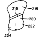
Figure 16 is the top view of Shoe socks the 6th embodiment of the present invention;
Figure 17 a is the side view that is in the 6th embodiment of the non-compression position that loosens;
Figure 17 b is the side view that is in the 6th embodiment of half compression position, so top branch contacts with bottom branch;
Figure 17 c is the side view that is in the 6th embodiment of compression position;
Figure 18 is the top view of the 6th embodiment, has shown each effective length of branch-off element; And
Figure 19 is the schematic illustration of load L on Shoe socks of the present invention.
The specific embodiment
With reference to figure 1-8, the present invention is a shoe system 10, and it has the resilient shoe insert 11 that comprises rigidity first support component 12, and described rigidity first support component 12 can be made by the suitable material of carbon fiber-reinforced composite material or other relative stiffness.First element 12 has elasticity and flexible front end 14 and stiff aft end 16.Front end 14 has cavity part 18, and it stops in the end 20 that is bent upwards slightly.Be appreciated that front end preferably made by elasticity and flexible material, it can cut typing by a scissors, so that the shape of front end 14 adapts to the shape of shoe system and pin.Use the Another reason of elastomeric material to be at front end 14 places, when walking with when mobile, toe can cooperate with front end 14 fully.
A key character of the present invention is: second element 36 be can recover shape with resilient, and first element 12 is rigidity basically except flexible toe portion.Explain as following, the low weight people of heavier people can select second element of rigidity more, stand in when inserting second element 36 on first element 12 when accommodating in mouthfuls 34 with the heavier people of box lunch, prevent second element 36 near or rely on first element 12.Preferably, second element 36 is rigidity enough, even therefore the people uses Shoe socks 11, the second elements 36 that are arranged in the shoes can not reduce as far as possible tempestuously.For example, when the people is upright (as shown in Figure 5), so Shoe socks 11 bears maximum weight, the minimum angles α that first element 12 forms with respect to second element 36, but this angle is non-vanishing.As shown in Figure 6, when crooked his/her knee of people or when turning forward, angle [alpha] increases, so the more weight of health is by the front support of pin, and weight still less is applied on second element 36.This also is preferred, the rigidity of second element 36 and be shaped as such, even so that the people jumps or when using shoes 48 tempestuously, first element 12 can not reduce as far as possible.
Determine the other factors of what rigidity of second element, 36 usefulness to comprise the Activity Type that shoes are used for, and walking/running road surface is hard, softness or uneven.The shape of second element 36 also can change according to user's needs.For example, have more that second element of bent front ends produces bigger gap 46 between second element and first element, when second element inserts in the support 32.The risk that bigger gap 46 can reduce to reduce as far as possible also can change the angle between pin and the ankle.
Because first element 12 is rigidity, the shape of first element is held, and for pin provides sufficient support, though second element 36 may move with respect to first element 12.In other words, first element 12 provides the excellent support to pin, though second element 36 can be compressed against on first element 12, how to be used according to shoes, and for example in sports, second element 36 is allowed to be returned to the expanded position of loosening after a while.
As preferably illustrating in Fig. 2, shoes 48 can have shaping sole 50, and it has and is configured as the upper surface 52 of snugly accommodating Shoe socks 11.Shoes 48 have heel part 51 and toe portion 53.Sole 50 is preferably made by the elastomeric material of for example rubber or plastics.Upper surface 52 has front portion 54, protruding mid portion 56 that is bent upwards and the rear portion 58 that is bent upwards slightly, so that support the part 20,26 and 24 of first element 12 respectively.
The important sole that is characterised in that defines an angular curved groove 60, and it is sized to can accommodate second element 36.Groove 60 extends back and downward heel 62 inclinations towards shoes 48.A leg-of-mutton wedge 64 is set between upper surface 52 and groove 60.Wedge 64 is connected to sole 50 removably, therefore removes wedge 64 easily, makes and can insert and remove particularly second element 36 of Shoe socks 11 easily.Wedge 64 is made by very resilient material, therefore when the weight of second element 36 by the user by towards 12 promotions of first element time, wedge 64 corresponding deformations and compression.
When second element 36 by towards 12 extruding of first element time, so Shoe socks 11 is in compression position, forming overvoltage in 72 at interval, flows out in its flow channel 70 and by valve 66, ventilates so that the inner favorable mechanical of shoes to be provided.Be allowed to when compression position is returned to it away from the original expanded position of first element 12 at second element 36, the any negative pressure that in interval 72, forms, can suck air by the top 74 from shoes 48 and be compensated, for example the open area from opening 76 or contiguous shoestring 78 sucks air.Should be appreciated that valve 66 also can be a two-way valve, so valve can be used for the overvoltage and the negative pressure of backoff interval 72.Like this, when second element 36 is allowed to when compression position is expanded, valve 66 can play the effect of circulation, and cold air may be brought into or sucked in the shoes.A filter 79 also can be set, when Shoe socks 11 is expanded, to prevent that dust and other undesirable particle from entering shoes 48 inside in the valve 66.
As preferably illustrating in Fig. 3, when the people did not uprightly have lateral tilt, first element 12 and second element 36 were substantially parallel.First element 12 can have vertical sidewall 81,83, to prevent the pin lateral sliding and apply unsuitable pressure on the shoes sidewall.Yet, when the people is mobile in lateral, therefore ankle 90 is in obliquity, the distribution of weight of shoes may be uneven, as shown in Figure 4, therefore second element 36 reverses slightly with respect to rigidity first element 12, to produce twisting action power around the Outboard Sections 82 of second element 36.Second element 36 has first thickness d on inside part 80
1, and on Outboard Sections 82, have second thickness d
2Second thickness d
2Greater than first thickness d
1, therefore when ankle 90 sloped inwardly, second element 36 only was allowed to reverse with respect to rigidity first element 12, as shown in Figure 4, if shown shoes 48 are the shoes that are used for right crus of diaphragm.In other words, second thickness that is in Outboard Sections 82 is enough thick, makes Outboard Sections 82 enough rigidity of second element 36, thereby can prevent any the relatively moving between Outboard Sections 82 places, first element 12 and second element 36.Because inside part 80 is coilable, when people's two legs separate when standing farly, still less need be with respect to the crooked ankle of pin, thereby ankle institute is stressed just littler.For example, when wait was received in tennis, it was very general that two legs separate far standing.Stressed another the excessive situation of ankle is when running along the road surface of lateral tilt.Inside part 80 reverse the risk that sprains one's foot that causes usually still less because as the result of the ankle that slopes inwardly, the angle between ankle and the pin changes and is reduced.
Fig. 7 has shown an optional embodiment of the present invention.Shoe socks 100 comprises the rear support portion 102 of a prolongation, and it extends partly to protect heel string and heel above the heel of pin.Support section 102 has reduced any excessive friction between heel and the shoes rear inside wall.Because Shoe socks 11 compressions and expansion, excessive friction may cause getting blister.Similar with Shoe socks 11; Shoe socks 100 has rigidity first element 104, elasticity second element 106 and flexible and flexible front end 108; front end 108 extends to protect the toe portion 109 places termination of toe above being positioned at toe, and while toe portion 109 can be followed Shoe socks and be moved together.Can adhere to a resilient rubbber cushion at the bottom side of front end 108 so that other comfortableness to be provided.Shape at an angle alpha between first element 104 and second element 106.This embodiment is useful especially to the heavily loaded boots of operation footwear and other form.
As preferably illustrating in Fig. 8, the transitional region 77 between first element 12 and soft and flexible front end 14 can be crooked part, and it is shaped according to the pin supporting zone that is arranged on the toe back.
Fig. 9 is the top view of second embodiment of Shoe socks of the present invention.Shoe socks 200 has transitional region 202 (it is equivalent to the transitional region 77 of Fig. 8), and transitional region 202 is extended with certain angle, so that will grow than the distance (y) at 206 places in the outside in the distance (x) at Shoe socks 200 inboard 204 places.In other words, flexible member at inboard 204 places than in the outside 206 places longer, therefore inboard 204 can crooked (as shown in Figure 4) and the outside 206 is relative stiffnesses.Similarly, Figure 10 has shown the top view of the Shoe socks 210 that is used for the left foot shoes, and Shoe socks 210 has transitional region 211 and inboard 212, the described inboard 212 longer length (x) of length (y) that have than inboard 214.Figure 11 is the upward view of third embodiment of the invention.Have more soft inside part 222 and the flexible member 220 than rigidity Outboard Sections 224 except having, Shoe socks 216 has the transitional region 218 of inclination.In the 3rd embodiment, transitional region needn't be extended with certain angle, because inside part 222 is more soft than Outboard Sections 224.Figure 12 is the side view of Shoe socks 230, Shoe socks 230 has a plurality of flexible members 232,234,236 that are connected to Shoe socks 230 downsides 238, and therefore the elasticity on inboard and the outside can be regulated according to Shoe socks 230 users' real needs.
Figure 13 and 14 has shown the 5th embodiment of the present invention.Shoes 300 have the sole 302 that comprises upper layer 303, and Shoe socks 304 integrates with sole 302 or as its part.Shoes 300 have toe portion 330 and heel part 332, and sole 302 has bottom side 305.Liner 304 has the upper segment 306 and the flexible lower segment 308 of relative stiffness, and lower segment 308 is connected to the downside 310 of fragment 306 at mid portion 312 places of upper segment 306.Preferably, fragment 306 is connected to a rear portion sheet 301, and rear portion sheet 301 is arranged on upper segment 303 near shoes 300 rear sides 309 places.Upper segment 306 and lower segment 308 have the interval 307 that is limited between them.307 can be filled with air or the very easy materials that compress and expand at interval.307 can completely or partially be filled with material at interval.For example, described material can comprise that the fragment of elastomeric material is to change the elastic characteristic of liner 304.Can use the elasticity fragment of rigidity more if the people is heavier, if physiognomy is to gentlier using the fragment or the fragment of rigidity more not still less.
One important be characterised in that fragment 306 be rigidity and be connected to sole, though therefore lower segment 308 may move with respect to upper segment 306, fragment 306 can not move with respect to shoes.This means the pin that inserts in the shoes 300 to remain on same position and no matter the bending motion of lower segment 308.When bottom fragment 308 is in expanded unloaded position (referring to Figure 13), the distance between upper segment 306 and sole 302 bottom sides 305 is a distance (A).Yet, do the time spent (referring to Figure 14) when be subjected to load (L) at shoes 300, lower segment 308 moves to compression position towards upper segment 306, and the distance between upper segment 306 and the bottom side 310 is reduced to distance (B), it is less than distance (A).When bottom fragment 308 was in compression position, fragment 308 upwards promoted upper segment 306 and enters expanded position.
Important being characterised in that of the present invention, when lower segment 308 was in expanded position as shown in Figure 13 and is in as shown in Figure 14 compression position, upper segment 306 all is arranged on to be left top edge 314 certain distances (X) and locates.This means on the pin 316 that is placed in the shoes 300 to produce bubble there is very little risk between pin 316 and shoes 300, do not have relative motion.
With reference to figure 15A-D, Shoe socks of the present invention is preferably by using special drawing method to make.Described method depends on instrument 400, and it has top assembly 402 and lower component 404.Assembly 402 has the cavity 406 that is limited to wherein, and cavity 406 has the shape identical with upper segment 306, and assembly 404 has the cavity 408 that is limited to wherein, and cavity 408 has the shape identical with lower segment 308.As preferably illustrating among Figure 15 B, assembly 404,406 is separated mutually.As being illustrated by arrow A 1, the top assembly 410 of pre-preg is placed on cavity 406 inside.Assembly 410 has elongated fore-end 409 and elongated rear end part 411, and the shape of assembly 410 is similar to the shape of cavity 406.The lower component 412 of pre-preg is placed in the cavity 408, and has the shape that is similar to cavity 408.Preferably, assembly 410,412 and 414 is made by polymer composites, for example is impregnated with the carbon and/or the glass fiber-reinforced body of suitable resin.Described assembly can completely or partially flood.Preferably, the toe portion of assembly 410,412 is partly flooded the flexible that improves to obtain.Resin can be the thermoplastic that is fit to, for example thermoplastic polyester, perhaps thermosetting resin, for example epoxy resin.Certainly, the polymer that also can use other to be fit to.
As preferably illustrating in Figure 15 c, when the assembly 410,412 of having placed the 3rd assembly 414 between it was placed correctly under in the tool assembly 402,404, assembly 402,404 was moved towards each other, shown in arrow A 2 and A3.The resin of assembly 410,412 assembly 402,404 applied the pressure a few minutes between the 2-40 crust, and temperature is elevated between 100-250 ℃, so that can make the thermoplastic resin fusing or thermosetting resin is solidified.Before assembly removed from instrument 400, instrument 400 can be cooled off then fast.
When assembly 410,412,414 is solidified into whole Shoe socks 424, tool assembly 402,404 is separated mutually and shift out liner 424 from assembly 402,404, as by among Figure 15 D shown in the arrow A 4.Liner 424 is about to integrate or embed in the sole with sole now, as liner 304 shown in Figure 13-14.
Figure 16 has shown the 6th embodiment of resilient shoe insert 500 of the present invention.Liner 500 also can be placed in the shoes 300, as shown in Figure 13-14, and replaces the liner 304 that is arranged on shoes 300 inside.Liner 500 has straight front-end 502, rounded back end 504 and the narrow mid portion 506 of inclination.Liner 500 can be made by composite, for example continuous fiber, and it for example extends around front end 502 and gets back to rear end 504 from outboard end 520 from the rear end 504, for example gets back to outboard end 522.Described fiber also can only extend to front end from the rear end.
With reference to figure 17a-c, Shoe socks 500 has top branch 506, and it has a straight line top branch fragment 508 that stops in recessed upper segment 510.Branch's fragment 508,516 also can be recessed slightly.Preferably, fragment 508,516 is more not recessed than fragment 510.Fragment 510 extends to front end 502, and it is a junction fragment 512.Described fragment can be fragment or any other suitable shape crooked or point, and the present invention is not limited to fragment crooked or point.Liner 500 has bottom branch 514, and it has the straight line bottom branch fragment 516 that stops in recessed lower segment 518, and the female lower segment 518 is adjacent with recessed upper segment 510.Fragment 518 extends to front end 502.Like this, the fiber of liner 500 can be walked around bent segments 512 from top branch 506 and extend to bottom branch 514.Top branch 506 has top end points 520, and bottom branch 514 has bottom end points 522, and when liner 500 was not compressed, bottom end points 522 and top end points 520 separated certain apart from d1, as shown in Figure 17 A.Liner has the effective length l1 that extends to end points 520,522 from front end 502.The shape that is appreciated that branch 506,514 can be straight line, recessed, projection or any suitable shape, and the hardness of branch 506,514 can be identical, and perhaps the hardness of branch 506 can be different with the hardness of branch 514.
Figure 17 B has shown the liner 500 that is in half-compression position, and therefore recessed upper segment 510 contacts with recessed lower segment 518 in contact fragment or contact point 524.Distance between the end points 520,522 from distance d1 be reduced to than distance d1 shorter apart from d2.The effective length of top branch 506 and bottom branch 514 is reduced to the length l 2 shorter than length l 1 from length l 1.Effective length l2 extends to contact fragment 524 from putting 520,522.
Figure 17 C has shown the liner 500 that is in compression position, so top branch 506 and bottom branch 514 prolong on the zone 526 at one and contact, and described prolongation regional 526 starts from contact point 524 and extends rearward to burble point 528.When liner bore enough big load L, described contact can extend rearward to end points 520,522 always.Distance between end points 520 and end points 522 from distance d2 be reduced to than distance d2 shorter apart from d3.The effective length of branch 506,514 is reduced to shorter length l 3 from length l 2.Therefore preferably, liner 500 is placed on shoes inside, as shown in Figure 13 and 14, uses the people of these shoes can compression gaskets 500, as shown in Figure 17 A-C.
Figure 18 is the top view of liner 500, and has shown first side at liner 500, effective length ratio second side of the branch on the outside 530 for example, and for example the effective length of the branch on inboard 532 will be lacked.As early pointing out, front end 502 and contact fragment 524 with a sharp angle inclination with respect to Shoe socks longitudinal direction L.Therefore effective length l3 changes according to the width W of Shoe socks.Effective length l on the outside 530
3oThan the effective length l on the inboard 532
3iLack.This makes the outside 530 of liner 500 harder than inboard 532, is similar in the embodiment shown in Fig. 9 and 10.The harder outside makes liner 500 and thereby makes shoes firmer.Same, the effective length l of branch
2, l
3Short more, it is hard more that liner 500 becomes.Like this, hardness not only changes by imposed load on liner 500, and hardness is also according to the wide variety of segregation section 528.Angle between fragment 524 and the longitudinal axes L can be as by the variation shown in contact fragment 524a and the 524b.Preferably, if the user needs liner 500 to have different hardness properties, liner 500 can be removed and replace from shoe system.
Figure 19 is apart from the schematic illustration of d on x load on axle L and the y axle.Further will be reduced to littler raising apart from d2 apart from the surprising load L of d3 needs.Need very little load L with will be apart from being reduced to d2.Yet further will need a considerable amount of load to increase apart from being reduced to d3.Its relation is not linear but index.
Though the present invention describes according to preferred structure and embodiment, be appreciated that and make certain replacement and change and not break away from the spirit and scope of following claim it.
Claims (7)
1. a use has the method for the shoe system of a resilient shoe insert, comprising:
Shoes (300) with the Shoe socks (500) that is arranged on described shoes inside are provided, described Shoe socks has top branch (506) and bottom branch (514), they connect by the front end (502) with junction fragment, top branch (506) has the recessed fragment (510) in top, top branch (506) has top end points (520), and bottom branch (514) has the bottom end points (522) with top end points (520) distance of separation (d1), and liner (500) has effective length (l
1);
On described shoes and liner (500), apply first load (L);
Top end points (520) is compressed towards bottom end points (522), recessed fragment (510) is recessed into fragment (518) with the bottom of described bottom branch and locates to contact at contact point (524) up to top, the junction fragment (512) that contact point (524) is located away from front end (502), therefore between junction fragment (512) and contact fragment (524), form a ring, contact fragment (524) is away from top end points and bottom end points (520,522); And
The recessed fragment in described top is being pressed against and the recessed fragment towards described bottom;
With described junction fragment bending,, formed a contact point up to when the recessed fragment in described top contacts with the recessed fragment in described bottom;
Apply second load on described shoes and described liner, described second load is basically greater than described first load;
At described contact point place with described top branch and the bending of bottom branch, to form a contact fragment, this contact fragment is extended from described contact point towards described upper and lower end points, and in the termination of burble point, thereby little by little improves the hardness of described upper and lower branch;
Contact fragment (524) is with effective length (l
1) be reduced to effective length (l
2), length (l
2) extend to upper and lower end points (520,522) from contact fragment (524).
2. the method for claim 1, it is characterized in that, described method comprises that further (530) extend to inboard (532) from the outside with contact fragment (524), and fragment (524) is basically parallel to front end (502), and front end (502) forms an acute angle with respect to described liner longitudinal axis (A).
3. method as claimed in claim 2, it is characterized in that, described method further comprises further to be compressed top end points (520) towards bottom end points (522), being reduced to than distance (d2) shorter distance (d3), and between top branch (506) and bottom branch (514), form contact area (526) apart from (d2).
4. method as claimed in claim 3 is characterized in that, described method further is included in contact fragment (524) mid portion (529) and locates effective length (l
2) shorten to effective length (l
3), length (l
3) than length (l
2) will lack.
5. method as claimed in claim 4 is characterized in that, described method further comprise liner (500) in the outside (530) locate to have effective length (l
3o), effective length (l
3o) effective length (l that locates than mid portion (529)
3) will lack.
6. method as claimed in claim 5 is characterized in that, described method comprises that further liner (500) locates to have effective length (l in inboard (532)
3i), effective length (l
3i) effective length (l that locates than mid portion (529)
3) will grow.
7. the method for claim 1 is characterized in that, described method comprises that further tie point (512) is set as crooked shape.
Applications Claiming Priority (2)
| Application Number | Priority Date | Filing Date | Title |
|---|---|---|---|
| US31973102P | 2002-11-25 | 2002-11-25 | |
| US60/319,731 | 2002-11-25 |
Publications (2)
| Publication Number | Publication Date |
|---|---|
| CN1713831A CN1713831A (en) | 2005-12-28 |
| CN100438793C true CN100438793C (en) | 2008-12-03 |
Family
ID=32392964
Family Applications (1)
| Application Number | Title | Priority Date | Filing Date |
|---|---|---|---|
| CNB2003801040114A Expired - Fee Related CN100438793C (en) | 2002-11-25 | 2003-10-08 | Shoe system with a resilient shoe insert |
Country Status (5)
| Country | Link |
|---|---|
| US (1) | US20060048411A1 (en) |
| EP (1) | EP1587384A4 (en) |
| CN (1) | CN100438793C (en) |
| AU (1) | AU2003282479A1 (en) |
| WO (1) | WO2004047579A1 (en) |
Families Citing this family (19)
| Publication number | Priority date | Publication date | Assignee | Title |
|---|---|---|---|---|
| US8056262B2 (en) * | 2003-10-08 | 2011-11-15 | Trackguard Ab | Shoe system with a resilient shoe insert |
| ES2310473B1 (en) * | 2007-04-16 | 2009-12-03 | Abraham Martinez Diaz | TROTIN FOR FOOTWEAR. |
| WO2009097589A1 (en) | 2008-01-31 | 2009-08-06 | Jeffrey David Stewart | Exercise apparatuses and methods of using the same |
| DE102009037837A1 (en) * | 2009-08-18 | 2011-02-24 | Stefan Lederer | Tread cushion for e.g. hiking shoe soles, has filling with preset shore hardness, where filling is provided in elastic brace element and fixedly connected with arms, and hardness determines damping effect and spring-back effect of cushion |
| US8893406B2 (en) * | 2010-02-09 | 2014-11-25 | Nike, Inc. | Footwear component for an article of footwear |
| US8479416B2 (en) * | 2010-02-09 | 2013-07-09 | Nike, Inc. | Footwear component for an article of footwear |
| US20120311887A1 (en) * | 2011-06-10 | 2012-12-13 | Peter Wong | Therapeutic Shoe Sole and Methods of Manufacturing the Same |
| US20130061494A1 (en) * | 2011-09-13 | 2013-03-14 | Danner, Inc. | Footwear with sole assembly having midsole plate and heel insert and associated methods |
| US9247784B2 (en) * | 2012-06-22 | 2016-02-02 | Jeffrey David Stewart | Wearable exercise apparatuses |
| US9066559B2 (en) * | 2012-06-27 | 2015-06-30 | Barry A. Butler | Bi-layer orthotic and tri-layer energy return system |
| US9943133B2 (en) | 2012-06-27 | 2018-04-17 | Barry A. Butler | Energy return orthotic systems |
| US9622540B2 (en) * | 2013-06-11 | 2017-04-18 | K-Swiss, Inc. | Article of footwear, elements thereof, and related methods of manufacturing |
| US9480303B2 (en) * | 2013-08-09 | 2016-11-01 | Nike, Inc. | Sole structure for an article of footwear |
| US9814280B2 (en) | 2015-08-12 | 2017-11-14 | Ariat International, Inc. | Heel dampening systems and footwear including the same |
| US20170127750A1 (en) * | 2015-11-10 | 2017-05-11 | Hattar Tanin LLC | Footwear with adjustable shock absorbing system |
| MX2019012479A (en) | 2017-04-24 | 2019-12-11 | a butler Barry | Energy return orthotic systems. |
| US10966482B2 (en) | 2018-10-12 | 2021-04-06 | Deckers Outdoor Corporation | Footwear with stabilizing sole |
| US11730228B2 (en) * | 2018-10-12 | 2023-08-22 | Deckers Outdoor Corporation | Footwear with stabilizing sole |
| US11723428B2 (en) | 2018-10-12 | 2023-08-15 | Deckers Outdoor Corporation | Footwear with stabilizing sole |
Citations (4)
| Publication number | Priority date | Publication date | Assignee | Title |
|---|---|---|---|---|
| US5396718A (en) * | 1993-08-09 | 1995-03-14 | Schuler; Lawrence J. | Adjustable internal energy return system for shoes |
| US5701686A (en) * | 1991-07-08 | 1997-12-30 | Herr; Hugh M. | Shoe and foot prosthesis with bending beam spring structures |
| US6247249B1 (en) * | 1999-05-11 | 2001-06-19 | Trackguard Inc. | Shoe system with a resilient shoe insert |
| US6449878B1 (en) * | 2000-03-10 | 2002-09-17 | Robert M. Lyden | Article of footwear having a spring element and selectively removable components |
Family Cites Families (4)
| Publication number | Priority date | Publication date | Assignee | Title |
|---|---|---|---|---|
| US324065A (en) * | 1885-08-11 | Spring-shank for boots or shoes | ||
| US4492046A (en) * | 1983-06-01 | 1985-01-08 | Ghenz Kosova | Running shoe |
| US4566206A (en) * | 1984-04-16 | 1986-01-28 | Weber Milton N | Shoe heel spring support |
| US5367790A (en) * | 1991-07-08 | 1994-11-29 | Gamow; Rustem I. | Shoe and foot prosthesis with a coupled spring system |
-
2003
- 2003-10-08 CN CNB2003801040114A patent/CN100438793C/en not_active Expired - Fee Related
- 2003-10-08 EP EP03774671A patent/EP1587384A4/en not_active Withdrawn
- 2003-10-08 US US10/531,116 patent/US20060048411A1/en not_active Abandoned
- 2003-10-08 WO PCT/US2003/031864 patent/WO2004047579A1/en not_active Application Discontinuation
- 2003-10-08 AU AU2003282479A patent/AU2003282479A1/en not_active Abandoned
Patent Citations (5)
| Publication number | Priority date | Publication date | Assignee | Title |
|---|---|---|---|---|
| US5701686A (en) * | 1991-07-08 | 1997-12-30 | Herr; Hugh M. | Shoe and foot prosthesis with bending beam spring structures |
| US6029374A (en) * | 1991-07-08 | 2000-02-29 | Herr; Hugh M. | Shoe and foot prosthesis with bending beam spring structures |
| US5396718A (en) * | 1993-08-09 | 1995-03-14 | Schuler; Lawrence J. | Adjustable internal energy return system for shoes |
| US6247249B1 (en) * | 1999-05-11 | 2001-06-19 | Trackguard Inc. | Shoe system with a resilient shoe insert |
| US6449878B1 (en) * | 2000-03-10 | 2002-09-17 | Robert M. Lyden | Article of footwear having a spring element and selectively removable components |
Also Published As
| Publication number | Publication date |
|---|---|
| CN1713831A (en) | 2005-12-28 |
| US20060048411A1 (en) | 2006-03-09 |
| AU2003282479A1 (en) | 2004-06-18 |
| WO2004047579A1 (en) | 2004-06-10 |
| EP1587384A1 (en) | 2005-10-26 |
| EP1587384A4 (en) | 2006-01-25 |
Similar Documents
| Publication | Publication Date | Title |
|---|---|---|
| CN100438793C (en) | Shoe system with a resilient shoe insert | |
| US8056262B2 (en) | Shoe system with a resilient shoe insert | |
| US6247249B1 (en) | Shoe system with a resilient shoe insert | |
| US9021719B2 (en) | Shoe spring and shock absorbing system | |
| US5138776A (en) | Sports shoe | |
| US7877897B2 (en) | Shoe | |
| US8316558B2 (en) | Shoe | |
| EP0206439A2 (en) | An outer sole for a basketball or like shoe | |
| US20030154628A1 (en) | Dynamic canting and cushioning system for footwear | |
| EP0741529A1 (en) | Elastomer midsole shoe structure | |
| US20020166184A1 (en) | Shoe system with a resilient shoe insert | |
| JPH0515444B2 (en) | ||
| CN207949062U (en) | A kind of elastic high-heeled shoes of variable coefficient | |
| CN207322820U (en) | A kind of elastic height increasing shoe pad | |
| CN105768350A (en) | Sports shoe sole structure capable of achieving telescopic effect along with telescopic motion of foot | |
| CN205611907U (en) | Can be according to flexible and flexible sports shoes sole structure of foot | |
| CN218389996U (en) | Sole that wear-resisting comfort level is high | |
| CN214103438U (en) | Sports shoe sole with shock attenuation massage function | |
| CN216701815U (en) | Sole and shoes with shock attenuation effect | |
| CN212139577U (en) | Multiple bradyseism supports sole | |
| CN219781721U (en) | Sports shoes and arch comfort level self-adaptation sole structure thereof | |
| CN218978150U (en) | Portable walking sole | |
| CN2352000Y (en) | Walk-aid high-heeled shoes | |
| CN1055387C (en) | Shoe construction with internal cushioning ribs | |
| CN116369633A (en) | High-elasticity durable damping part and application method thereof |
Legal Events
| Date | Code | Title | Description |
|---|---|---|---|
| C06 | Publication | ||
| PB01 | Publication | ||
| C10 | Entry into substantive examination | ||
| SE01 | Entry into force of request for substantive examination | ||
| C14 | Grant of patent or utility model | ||
| GR01 | Patent grant | ||
| ASS | Succession or assignment of patent right |
Owner name: FOOT GUARDS CO., LTD. Free format text: FORMER OWNER: FOOT GUARDS CO.,LTD. Effective date: 20090403 |
|
| C41 | Transfer of patent application or patent right or utility model | ||
| TR01 | Transfer of patent right |
Effective date of registration: 20090403 Address after: Sweden Danderyd Patentee after: Walking guards Holdings Ltd. Address before: Arizona USA Patentee before: Trackguard Inc. |
|
| CF01 | Termination of patent right due to non-payment of annual fee |
Granted publication date: 20081203 |
|
| CF01 | Termination of patent right due to non-payment of annual fee |