CN100449325C - Magnetometer having a dynamically adjustable bias setting and electronic vehicle compass incorporating the same - Google Patents
Magnetometer having a dynamically adjustable bias setting and electronic vehicle compass incorporating the same Download PDFInfo
- Publication number
- CN100449325C CN100449325C CNB028252284A CN02825228A CN100449325C CN 100449325 C CN100449325 C CN 100449325C CN B028252284 A CNB028252284 A CN B028252284A CN 02825228 A CN02825228 A CN 02825228A CN 100449325 C CN100449325 C CN 100449325C
- Authority
- CN
- China
- Prior art keywords
- sensor
- magnetometer
- magnetic field
- detecting element
- signal
- Prior art date
- Legal status (The legal status is an assumption and is not a legal conclusion. Google has not performed a legal analysis and makes no representation as to the accuracy of the status listed.)
- Expired - Lifetime
Links
- 230000005291 magnetic effect Effects 0.000 claims abstract description 400
- 230000004044 response Effects 0.000 claims abstract description 119
- 230000008859 change Effects 0.000 claims description 90
- 238000005259 measurement Methods 0.000 claims description 73
- 239000011162 core material Substances 0.000 claims description 47
- 238000000034 method Methods 0.000 claims description 43
- 238000001514 detection method Methods 0.000 claims description 38
- 238000005086 pumping Methods 0.000 claims description 28
- 238000005070 sampling Methods 0.000 claims description 27
- 238000001914 filtration Methods 0.000 claims description 24
- 239000003990 capacitor Substances 0.000 claims description 15
- 229920006395 saturated elastomer Polymers 0.000 claims description 15
- 230000006698 induction Effects 0.000 claims description 10
- 230000007246 mechanism Effects 0.000 claims description 10
- 238000013016 damping Methods 0.000 claims description 8
- 238000004804 winding Methods 0.000 claims description 8
- 230000015572 biosynthetic process Effects 0.000 claims description 5
- 238000004364 calculation method Methods 0.000 claims description 4
- 230000005405 multipole Effects 0.000 claims 4
- 238000013508 migration Methods 0.000 claims 1
- 230000037361 pathway Effects 0.000 claims 1
- 230000014509 gene expression Effects 0.000 description 17
- 230000004907 flux Effects 0.000 description 15
- 230000010363 phase shift Effects 0.000 description 15
- 238000013461 design Methods 0.000 description 14
- 230000005284 excitation Effects 0.000 description 12
- 238000006243 chemical reaction Methods 0.000 description 11
- 230000000694 effects Effects 0.000 description 9
- 239000000463 material Substances 0.000 description 9
- 238000012545 processing Methods 0.000 description 9
- 239000013598 vector Substances 0.000 description 8
- 230000002349 favourable effect Effects 0.000 description 7
- 230000006641 stabilisation Effects 0.000 description 7
- 238000011105 stabilization Methods 0.000 description 7
- 238000012360 testing method Methods 0.000 description 7
- 238000010586 diagram Methods 0.000 description 6
- 238000005516 engineering process Methods 0.000 description 6
- 230000001105 regulatory effect Effects 0.000 description 6
- 238000013459 approach Methods 0.000 description 5
- 230000000712 assembly Effects 0.000 description 5
- 238000000429 assembly Methods 0.000 description 5
- 230000010349 pulsation Effects 0.000 description 5
- 230000002441 reversible effect Effects 0.000 description 5
- 230000003068 static effect Effects 0.000 description 5
- 238000004519 manufacturing process Methods 0.000 description 4
- 238000007493 shaping process Methods 0.000 description 4
- 230000003442 weekly effect Effects 0.000 description 4
- 238000000137 annealing Methods 0.000 description 3
- 230000003139 buffering effect Effects 0.000 description 3
- 230000001276 controlling effect Effects 0.000 description 3
- 238000012937 correction Methods 0.000 description 3
- 230000008878 coupling Effects 0.000 description 3
- 238000010168 coupling process Methods 0.000 description 3
- 238000005859 coupling reaction Methods 0.000 description 3
- 238000013213 extrapolation Methods 0.000 description 3
- 230000008569 process Effects 0.000 description 3
- 230000002829 reductive effect Effects 0.000 description 3
- 230000000717 retained effect Effects 0.000 description 3
- XEEYBQQBJWHFJM-UHFFFAOYSA-N Iron Chemical compound [Fe] XEEYBQQBJWHFJM-UHFFFAOYSA-N 0.000 description 2
- 230000009471 action Effects 0.000 description 2
- 238000004458 analytical method Methods 0.000 description 2
- 230000008901 benefit Effects 0.000 description 2
- 230000005347 demagnetization Effects 0.000 description 2
- 239000006185 dispersion Substances 0.000 description 2
- 238000011156 evaluation Methods 0.000 description 2
- 230000000670 limiting effect Effects 0.000 description 2
- 238000012986 modification Methods 0.000 description 2
- 230000004048 modification Effects 0.000 description 2
- 230000001915 proofreading effect Effects 0.000 description 2
- 238000007634 remodeling Methods 0.000 description 2
- 230000000630 rising effect Effects 0.000 description 2
- 230000035945 sensitivity Effects 0.000 description 2
- 230000007704 transition Effects 0.000 description 2
- 230000004304 visual acuity Effects 0.000 description 2
- 238000012935 Averaging Methods 0.000 description 1
- 241000237970 Conus <genus> Species 0.000 description 1
- 238000004378 air conditioning Methods 0.000 description 1
- 230000033228 biological regulation Effects 0.000 description 1
- 230000005540 biological transmission Effects 0.000 description 1
- 239000002131 composite material Substances 0.000 description 1
- 230000009514 concussion Effects 0.000 description 1
- 230000001143 conditioned effect Effects 0.000 description 1
- 239000004020 conductor Substances 0.000 description 1
- 238000010276 construction Methods 0.000 description 1
- 230000006866 deterioration Effects 0.000 description 1
- 230000003292 diminished effect Effects 0.000 description 1
- 230000007613 environmental effect Effects 0.000 description 1
- 239000012467 final product Substances 0.000 description 1
- 230000008676 import Effects 0.000 description 1
- 230000001939 inductive effect Effects 0.000 description 1
- 238000007689 inspection Methods 0.000 description 1
- 230000010354 integration Effects 0.000 description 1
- 229910052742 iron Inorganic materials 0.000 description 1
- 238000011068 loading method Methods 0.000 description 1
- 239000000696 magnetic material Substances 0.000 description 1
- 238000012423 maintenance Methods 0.000 description 1
- 239000002184 metal Substances 0.000 description 1
- 229910052751 metal Inorganic materials 0.000 description 1
- 229910000697 metglas Inorganic materials 0.000 description 1
- 238000012544 monitoring process Methods 0.000 description 1
- 230000010355 oscillation Effects 0.000 description 1
- 230000035699 permeability Effects 0.000 description 1
- 238000007781 pre-processing Methods 0.000 description 1
- 230000009467 reduction Effects 0.000 description 1
- 238000003786 synthesis reaction Methods 0.000 description 1
- 230000002194 synthesizing effect Effects 0.000 description 1
- 230000009897 systematic effect Effects 0.000 description 1
- 238000012546 transfer Methods 0.000 description 1
- 230000001052 transient effect Effects 0.000 description 1
- 238000012795 verification Methods 0.000 description 1
- 230000000007 visual effect Effects 0.000 description 1
Images


Classifications
-
- G—PHYSICS
- G01—MEASURING; TESTING
- G01C—MEASURING DISTANCES, LEVELS OR BEARINGS; SURVEYING; NAVIGATION; GYROSCOPIC INSTRUMENTS; PHOTOGRAMMETRY OR VIDEOGRAMMETRY
- G01C17/00—Compasses; Devices for ascertaining true or magnetic north for navigation or surveying purposes
- G01C17/02—Magnetic compasses
- G01C17/28—Electromagnetic compasses
- G01C17/32—Electron compasses
-
- G—PHYSICS
- G01—MEASURING; TESTING
- G01R—MEASURING ELECTRIC VARIABLES; MEASURING MAGNETIC VARIABLES
- G01R33/00—Arrangements or instruments for measuring magnetic variables
- G01R33/02—Measuring direction or magnitude of magnetic fields or magnetic flux
- G01R33/028—Electrodynamic magnetometers
-
- G—PHYSICS
- G01—MEASURING; TESTING
- G01C—MEASURING DISTANCES, LEVELS OR BEARINGS; SURVEYING; NAVIGATION; GYROSCOPIC INSTRUMENTS; PHOTOGRAMMETRY OR VIDEOGRAMMETRY
- G01C17/00—Compasses; Devices for ascertaining true or magnetic north for navigation or surveying purposes
- G01C17/02—Magnetic compasses
- G01C17/28—Electromagnetic compasses
- G01C17/30—Earth-inductor compasses
-
- G—PHYSICS
- G01—MEASURING; TESTING
- G01R—MEASURING ELECTRIC VARIABLES; MEASURING MAGNETIC VARIABLES
- G01R33/00—Arrangements or instruments for measuring magnetic variables
- G01R33/02—Measuring direction or magnitude of magnetic fields or magnetic flux
-
- G—PHYSICS
- G01—MEASURING; TESTING
- G01R—MEASURING ELECTRIC VARIABLES; MEASURING MAGNETIC VARIABLES
- G01R33/00—Arrangements or instruments for measuring magnetic variables
- G01R33/02—Measuring direction or magnitude of magnetic fields or magnetic flux
- G01R33/0206—Three-component magnetometers
Abstract
A magnetometer includes at least one sensor (10) for sensing a magnetic fiel d component, a biasing circuit (6), and a processor (1). The sensor (10) generates an output signal having a signal characteristic that varies in response to the sensed magnetic field component and in response to an applie d bias. The biasing circuit (6) dynamically biases the sensor (10) in response to a bias setting signal. The processor (1) is coupled to receive the output signal from the sensor (10) and coupled to the biasing circuit (6). The processor (1) is operable to generate the bias setting signal (3) and thereb y control the biasing circuit (6) to dynamically bias the sensor such that the signal characteristic of the output signal is maintained in a target range. The processor (1) determines the magnetic field component sensed by the sens or (10) as a function of the bias setting applied to the sensor.
Description
Technical field
The present invention relates generally to a kind of magnetometer, relate in particular to the electronic compass that is used for vehicle.
Background technology
Magnetometer is used in many different application.A kind of application wherein is the electronic compass that is used for vehicle.In this electronic compass, utilize magnetometer to judge the travel direction of vehicle with respect to the magnetic north pole of the earth.A kind of typical electronic compass comprises two magnetic field sensors, the axis that these two magnetic field sensors are set to make them is in the surface level, make the longitudinal axis of the axis of first sensor and vehicle parallel, and make the axis normal of the axis and the first sensor of second sensor.Treatment circuit utilizes the amplitude that axially aligns component vertical, level of the magnetic vector of these sensor earth then, so that can calculate the travel direction of vehicle with respect to magnetic-field vector of the earth.
Utilize several multi-form magnetometers in the vehicle electric compass always.Some examples of the magnetometer of these types comprise the magnetometer that utilizes fluxgate sensor, magnetoresistive transducer and magnetic induction sensor.Magnetic induction sensor can constitute by the different form that comprises L/R sensor and LC sensor.In the magnetic induction sensor of described two kinds of forms, all has the coil that twines around core material.This sensor has such specific character, and promptly its inductance response magnetic field is change linearly, but just externally two predetermined scopes of the value in magnetic field are so interior.By observing the curve (for example see Fig. 5) of sensors inductance, can see that the curve of gained is zero point symmetry basically around magnetic field intensity to magnetic field intensity.Thereby, usually cell winding is applied a bias current, make around core material, to produce an artificial magnetic field.Artificial magnetic field and external magnetic field addition by described bias current generation.Direction is the addition each other of identical external magnetic field, magnetic field with the people who is produced by bias current, and direction is then deducted the magnetic field from the people for opposite external magnetic field, magnetic field with the people.Thereby, by means of the change of the inductance of survey sensor, can determine the intensity of the magnetic-field component of axial orientation.
For the change of the inductance of survey sensor, the circuit structure that a kind of response frequency changes with the change of the inductance of sensor has been proposed.Utilize sort circuit, the approximately proportional change of frequency of the change generation of the inductance of sensor and signal of sensor.Thereby change that can survey frequency, so that determine the intensity of external magnetic field.
A problem that runs in this magnetometer is that the characteristic of core material is with becoming temperature and tenure of use.A solution to this problem has disclosed in European patent No.0045509 B1.This European patent has disclosed: the polarity of the bias current on the cell winding can be reversed, and make to utilize the bias current of two kinds of polarity to measure, thereby the difference between two measurements is corresponding to the external magnetic field.The measurement of carrying out and irrelevant like this by any variation of the core material that causes temperature change or tenure of use.
U.S. Patent No. 5239264 has disclosed a kind of similar techniques.Fig. 1 of the application and Fig. 2 are corresponding to Fig. 3 and Fig. 4 of 264 patents.As depicted in figs. 1 and 2, the magnetoconductivity function u (H) of core material in a specific magnetic field intensity scope as the function of magnetic field intensity H and change.By these curves as can be seen, shown curve generally has two zones, and wherein magnetoconductivity is with respect to the change of magnetic field intensity and change.A zone has positive slope, and another zone has negative slope.In 264 patents, the reverse polarity of dc bias current alternately, thus the reading with two polarity is provided.Two readings are subtracted each other each other, thereby obtain magnetic field intensity by the one-component in that specific detected magnetic field of the earth of cell winding.
In above-mentioned United States Patent (USP) 5239264 and European patent 0045509B1, dc bias current remains constant, has only the polarity of bias current to be reversed.It is that automobile may cause the distortion of external magnetic field that a problem of electronic compass is provided in automobile.In addition, when vehicle by some objects, for example when bridge, subway, line of electric force, railway and other object, these objects may produce the magnetic field of being detected by electronic compass and disturb.This magnetic interference may produce the magnetic field that makes by the cell winding detection and drop on inductance to the magnetic field in the nonlinear area of magnetic field intensity curve.Thereby the magnetometer of above-mentioned patent has a limited scope, and they can accurately detect the intensity of external magnetic field in this scope.
Thereby, need a kind of electronic compass, accurately detect magnetic-field component in its bigger scope that can provide at magnetometer than current routine.
Summary of the invention
According to one embodiment of the present of invention, a kind of magnetometer is provided, it comprises the sensor that is used to detect magnetic field; Biasing circuit and processor.Described sensor produces has a kind of output signal of signal characteristic, and the magnetic field that described signal characteristic response detects also responds the biasing that applies and changes.The described biasing circuit response biasing signalization described sensor of dynamically setovering.Described processor is connected for receiving from described signal of sensor, and is coupled mutually with described biasing circuit.Described processor can be operated and be used for producing the biasing signalization, so as to controlling biasing circuit so that dynamically setover described sensor, so that keep the described signal characteristic of described output signal in the scope of relatively little desired value.Described processor is determined magnetic-field component by sensor according to the function that is applied to the biasing setting on the sensor.
According to an alternative embodiment of the invention, a kind of magnetometer is provided, it comprises: first sensor is used to detect first component in a magnetic field; Second sensor is used to detect the second component in described magnetic field; Biasing circuit; And processor.Each sensor produces the output signal with a frequency, and the component magnetic field that described frequency response detects also responds the bias current that applies and changes.Biasing circuit produces the bias current of described first and second sensors that are used for dynamically setovering.Described processor is connected for receiving from described sensor output signal, and is coupled mutually with described biasing circuit.Described processor can be operated and be used to control biasing circuit, so that dynamically change the bias current that puts on sensor, makes output signal frequency be maintained in one or several range of target frequencies.Described processor is determined magnetic-field component by described sensor according to the function of the bias current that puts on sensor.
According to another embodiment, a kind of electronic compass that is used for vehicle is provided, it comprises: first magnetic field sensor is used to detect first component in a magnetic field; Second magnetic field sensor, be used to detect described magnetic field with the vertical second component of described first component; Biasing circuit; Treatment circuit; And, be coupled travel direction indicator mutually with described treatment circuit with the travel direction that is used to indicate vehicle.Each sensor produces the output signal with a signal characteristic, and the component magnetic field that described signal characteristic response detects also responds the bias current that applies and changes.Biasing circuit produces the bias current of described first and second sensors that are used for dynamically setovering.Described processor is connected for receiving from described sensor output signal, and is coupled mutually with described biasing circuit.Described processor can be operated and be used to control biasing circuit, so that dynamically change the bias current that puts on sensor, so that the signal characteristic of output signal is maintained in one or several target zone.Described treatment circuit calculates the travel direction of vehicle according to the function of the bias current that puts on sensor.
According to an alternative embodiment of the invention, a kind of method that is used for the intensity of definite magnetic-field component is provided, may further comprise the steps: a magnetic field sensor is provided, its generation has the output signal of a signal characteristic, and the intensity of the magnetic-field component that described signal characteristic response detects also responds the biasing setting that applies and changes; Dynamically change the biasing setting of described sensor, so that the described signal characteristic of described output signal is maintained in the target zone; And, determine the intensity of the magnetic-field component that detects according to the function of the biasing setting of described sensor.
According to an alternative embodiment of the invention, a kind of magnetometer is provided, it comprises: the sensor that is used to detect a magnetic-field component; A magnetic field produces mechanism; And a processor, described processor is connected for receiving from signal of sensor and produces mechanism with described magnetic field and is coupled mutually.Described sensor produces the output signal with a feature, and described feature responds described detection in first scope of magnetic field value magnetic-field component changes substantially linearly.Described magnetic-field component changes in one second scope of magnetic field value.Described magnetic field produces the magnetic field of mechanism's generation and the addition of any external magnetic field, so that synthetic magnetic field is by described sensor.The intensity in the magnetic field of described generation selectively changes.Described processor can be operated and be used to control described magnetic field and produce mechanism, so that select the intensity in the magnetic field that produces, and dynamically changes in described first scope thus and/or keeps described second scope.Described processor can also be operated and be used to respond the definite magnetic-field component by described sensor of output signal that receives from sensor.
According to another embodiment, a kind of magnetometer is provided, it comprises: have a response magnetic field and the detecting element of the sensor characteristics that changes; And, a amplifier with the input end that is used to receive drive signal.Described detecting element is coupled in the feedback loop of described amplifier.Described amplifier produces has the output signal of a signal characteristic, and described signal characteristic responds the change of described sensor characteristics at least in part and changes.
According to another embodiment, a kind of magnetometer comprises: first detecting element with the sensor characteristics that responds a magnetic field and change; Second detecting element of the sensor characteristics that has a magnetic field of response and change; Be provided for one first analog switch selecting described first detecting element; Be provided for one second analog switch selecting second detecting element; And a processor, it is connected for receiving from selected one output signal of first and second detecting elements, and is coupled mutually with described first and second analog switches, to be used for selecting of first and second detecting elements.
According to another embodiment, a kind of magnetometer comprises: be used to detect the sensor in magnetic field, described sensor produces has the output signal of a signal characteristic, and the magnetic field intensity that described signal characteristic response detects also responds the biasing that applies and changes; First and second high-gain amplifiers, each has an input end, and one of described amplifier is coupled mutually with described sensor; Be used to the to setover biasing circuit of described sensor, described biasing circuit is connected between the input of described first and second high-gain amplifiers; And a processor that is connected for receiving from described signal of sensor, described processor is determined the magnetic-field component by described inspection sensor.
According to another embodiment, a kind of magnetometer comprises: be used to detect the resonant transducer in magnetic field, described sensor produces has the output signal of a signal characteristic, and described signal characteristic responds the magnetic field of described detection and biasing that response applies and changes; Biasing circuit is used for for each bias polarity with two or more bias stages (bias level) described sensor of setovering adjustablely; And be connected for receiving processor from described signal of sensor, described processor is determined the magnetic-field component by described sensor, wherein, during a harmonic period, the peak value of the magnetic field value in described resonant transducer is the sub-fraction of the magnetic field value deviation range that the adjusting of its whole range of adjustment caused owing to biasing circuit to the skew of peak value.
According to another embodiment, a kind of magnetometer comprises: be used to detect the resonant transducer in magnetic field, described sensor produces the output signal of a signal characteristic that has the magnetic field of response detection and change; And processor that is connected for receiving from described signal of sensor, described processor is determined the magnetic-field component by described sensor, wherein, during harmonic period, the peak value of the magnetic field value in resonant transducer to the skew of peak value less than total scope of wanting measured magnetic field.
According to another embodiment, a kind of magnetometer comprises: be used to detect the resonant transducer in magnetic field, described sensor produces the output signal of a signal characteristic that has the magnetic field of response detection and change; The exciting circuit that links to each other with described resonant transducer, be used for it is provided pumping signal, the amplitude of described exciting circuit restriction pumping signal, thus stop resonant transducer serious saturated to the response of pumping signal; And a processor that is connected for receiving from described signal of sensor, described processor is determined the magnetic-field component by described sensor.
According to another embodiment, a kind of magnetometer comprises: be used to detect the resonant transducer in magnetic field, described sensor produces one to have the magnetic field of response detection and responds the biasing that applies and the output signal of the signal characteristic that changes; Biasing circuit is used for two or more bias stages described sensor of setovering adjustablely; And a processor that is connected for receiving from described signal of sensor, described processor is according to from the function of the signal characteristic of signal of sensor and according to described output signal the function of the slope of bias being determined magnetic-field component by described sensor.
According to another embodiment, a kind of magnetometer comprises: be used to detect the resonant transducer in magnetic field, described sensor produces one to have the magnetic field of response detection and responds the biasing that applies and the output signal of the signal characteristic that changes; Biasing circuit is used for at least the first bias stage and the second bias stage described sensor of setovering adjustablely; And a processor that is connected for receiving from described signal of sensor, described processor is according to the definite magnetic-field component by described sensor of the function of the mean value of output signal value when being in first and second bias stages.
According to another embodiment, a kind of magnetometer comprises: first detecting element, and it has the sensor characteristics that responds a magnetic field and change; Second detecting element, it has the sensor characteristics that responds a magnetic field and change; Biasing circuit is used for described first detecting element is biased at least the first bias stage and second bias stage adjustablely, and described second detecting element is biased at least the three bias stage and the 4th bias stage adjustablely; And the processor that links to each other with the described biasing circuit and first and second detecting elements, be used to receive output signal from detecting element.Described processor is measured the magnetic-field component that is detected by described detecting element by carrying out following operation in order: the output signal of first detecting element of sampling under described first bias stage, the output signal of second detecting element of sampling under described the 3rd bias stage, the output signal of second detecting element of sampling under described the 4th bias stage, the output signal of first detecting element of sampling under described second bias stage, determine the magnetic-field component of first detecting element according to the function of the sampling of under first and second bias stages, carrying out, determine the magnetic-field component of second detecting element according to the function of the sampling of under third and fourth bias stage, carrying out.
According to another embodiment, a kind of magnetometer comprises: first detecting element, and it has the sensor characteristics that responds a magnetic field and change; Second detecting element, it has the sensor characteristics that responds a magnetic field and change; At least one analog switch, it is provided for selects first or second detecting element, and described at least one analog switch has resistance; Biasing circuit is used for selected one of detecting element is applied bias current; And processor, it is connected for receiving one output signal from the selection of first and second detecting elements, and link to each other with described at least one analog switch, so that select one of first and second detecting elements, described processor is determined the magnetic-field component by described detecting element detection, wherein, described biasing circuit is constructed for applying basically and the irrelevant bias current of the resistance of described at least one analog switch.
According to another embodiment, a kind of magnetometer comprises: first detecting element, and it has the sensor characteristics that responds a magnetic field and change; Second detecting element, it has the sensor characteristics that responds a magnetic field and change; At least one analog switch, it is provided for selects first or second detecting element; Biasing circuit is used for described detecting element is biased at least the first bias stage and second bias stage adjustablely; And processor, it is connected for receiving the output signal from that selects in first and second detecting elements, and link to each other with described at least one analog switch, so that select one of first and second detecting elements, described processor determines that wherein, described biasing circuit is at detecting element of the first bias stage below-center offset by the magnetic-field component of described detecting element detection, subsequently at the same detecting element of the second bias stage below-center offset, and do not change the state of analog switch.
According to another embodiment, a kind of magnetometer comprises: be used to detect the sensor in magnetic field, described sensor produces one to have the magnetic field of response detection and responds the bias current that applies and the output signal of the signal characteristic that changes; Biasing circuit is used for the described sensor of setovering adjustablely, and described biasing circuit comprises digital to analog converter; And treatment circuit, it comprises a readout device that is connected for receiving from described signal of sensor, described treatment circuit is measured magnetic-field component by described sensor by receiving from least one reading of described signal of sensor, wherein, the resolution that reads described output signal is the function of described digital to analog converter and described readout device.
According to another embodiment, a kind of method that is used to make a plurality of magnetic field detection inductors is provided, comprise the following step of carrying out in order: the magnetic core that is provided for each magnetic field detection inductor; Test the magnetic core of described each magnetic field detection inductor; And on described each magnetic core, twine a coil, adjust the number of turn of the coil on each magnetic core according to the test result of described magnetic core.
According to another embodiment, a kind of magnetometer is provided, comprising: be used to detect the resonant transducer in magnetic field, described sensor produces the output signal of a signal characteristic that has the magnetic field of response detection and change; With the exciting circuit that described resonant transducer links to each other, be used for providing pumping signal with AC compounent to described resonant transducer; Be used for before described pumping signal is applied to described resonant transducer described pumping signal filter filtering, described wave filter makes the approximate sine that becomes of described pumping signal; And being connected for receiving processor from described signal of sensor, described processor is determined the magnetic-field component by described sensor.
According to another embodiment, a kind of magnetometer comprises: be used to detect the sensor in magnetic field, described sensor produces one to have the magnetic field of response detection and responds the bias current that applies and the output signal of the signal characteristic that changes; Biasing circuit is used to respond a biasing setting and regulates the bias current that is applied to described sensor; And processor, it is connected for receiving from described signal of sensor, and link to each other with described biasing circuit and to be used to provide biasing setting, the function that described processor is provided with according to biasing is determined the magnetic-field component by described sensor, wherein, be selected for the biasing setting of determining magnetic-field component based on reach the poor of bias current on 2 an of target response in output signal.
According to another embodiment, a kind of magnetometer comprises: be used to detect the sensor in magnetic field, described sensor produces one to have the magnetic field of response detection and responds the bias current that applies and the output signal of the signal characteristic that changes; Biasing circuit is used to respond a biasing bias current that adjusting is applied to described sensor is set; And processor, it is connected for receiving from described signal of sensor, and link to each other with described biasing circuit and to be used to provide biasing setting, the function that described processor is provided with according to described biasing is determined the magnetic-field component by described sensor, wherein, be selected for the biasing setting of definite magnetic-field component based on no more than 5 the original reading formerly that obtains from described sensor.
By consulting following instructions, claims and accompanying drawing, those skilled in the art can further understand these and other feature, advantage and purpose of the present invention.
Description of drawings
In the accompanying drawings:
Fig. 1 represents the curve of the waveform relevant with the magnetometer of the prior art that does not apply the external magnetic field;
Fig. 2 represents the curve of the waveform relevant with the magnetometer of the prior art that applies the external magnetic field;
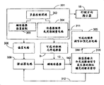
Fig. 3 is the circuit block diagram according to the magnetometer of first embodiment of the present invention formation;
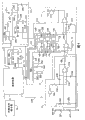
Fig. 4 is the circuit block diagram with a kind of enforcement of the magnetometer of first embodiment that represents of form of signal;
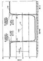
Fig. 5 can be used for the curve of the frequency of sensor of the present invention to electric current;
Fig. 6 can be used for the curve of the frequency of two different sensors of the present invention to electric current;
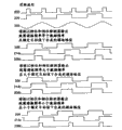
Fig. 7 represents each waveform that can be produced by the various piece of the circuit of Fig. 4;
Fig. 8 is the circuit block diagram according to the magnetometer of second embodiment of the present invention formation;
Fig. 9 is the calcspar and the schematic diagram of an enforcement that is used to illustrate the magnetometer of second embodiment;
Figure 10 is the curve as the A/D counting of the function of the PWM bias of the magnetometer that constitutes according to the present invention; And
Figure 11 is the skeleton view that comprises the rearview mirror device for vehicle of electronic compass of the present invention.
Embodiment
Now present preferred embodiment of the present invention is elaborated, the example of the preferred embodiments of the present invention is shown in the drawings.Under possible situation, in institute's drawings attached, use identical label to represent identical or similar parts.
A kind of required detection method that magnetometer uses is the method according to a kind of zero balancing operate of modification, utilize this method, use saturable induction detecting element as sensor, and dynamically adjust bias current and reach and maintain induction saturated measurable in the detecting element and dbjective state repeatably.Thereby, different with the magnetometer of the fixing bias current of the utilization of routine, magnetometer of the present invention dynamically changes bias current, so as in a target zone, keeping the characteristic of sensor output signal, simultaneously according in order to keep output signal characteristics at the required bias current of described desired value with determine the relevant intensity of the magnetic field strength component of detection according to the output valve in described target zone.For example, if the change bias current maintains the output of the interior detecting element of the target zone of frequency or phase place, then in the linear segment operation of the inductance curve of sensor, detecting element will continue detection magnetic field, and the amplitude in the magnetic field at tube sensor place not.Thereby magnetometer of the present invention is compared with conventional magnetometer, has a scope that significantly increases.
In the described below preferred embodiment, provide a biasing circuit, it can be adjusted to be provided for reading all biasing settings of magnetic field intensity by a scope.This scope is enough big, thereby comprises to the inductance of substantial symmetry to the ability of any side (promptly in any one target zone) offset sensors of bias current curve and for this reason and the ability of the influence of compensation external magnetic field.In a preferred embodiment, generally the reading for each magnetic field intensity is provided with one or several biasing setting, and these settings generally comprise the setting to the biasing of each of two different range, for described scope, the amplitude of the resultant magnetic field value in magnetic test coil is approximately equal to the reference value as target of selection, but direction is opposite.When resultant magnetic field value during near its target reference value (in target zone), the output that is monitored of circuit then near with a corresponding target output value of magnetic field value that equals described reference value.In operation, by regulating bias so that the resultant magnetic field value in the sensor magnetic core is carried out first biasing near its reference value to be provided with, and in processing, offset at least in part or compensation in vehicle will be measured magnetic field and effect combination or total of disturbing magnetic field.Read the circuit output of the state of saturation of expression sensor magnetic core, and the bias current that is corrected with this prediction of output first, it should produce the bias magnetic field of the sensor magnetic core that approaches its target reference state and the degree of saturation of synthesizing.This value can be selectively with the unit representation outside the bias current.Carry out second biasing and be provided with, so that bias magnetic field arrives another scope with reference to magnetic field value, the direction in the reference magnetic field in measuring magnetic core is opposite with described another direction with reference to magnetic field.Measure the output of the state of saturation of expression magnetic core in the mode that is similar to the first biasing reading, and determine second biasing that is corrected.What first and second bias currents that are corrected or relevant value were used for determining approx striking total external magnetic field of measuring on the coil axially aligns component or its functional representation.
Measurable saturated dbjective state or pseudozero point are such states, and for this state, the flux value of the reality of general induction pick-up for example is several thousand times of Minimum Increment of the outside magnetic flux that need to detect.Suitable induction detecting element has a kind of performance, and it provides a kind of method that is used for avoiding in intrinsic many problems of big magnetic flux biasing, and for the detectable pseudozero point of a satisfaction, this generally needs.By selecting core material suitably, the saturation characteristic of induction detecting element depends primarily on the amplitude in the magnetic field in the magnetic core, and almost gets which orientation independent of two axial directions with magnetic field.Thereby, in order to measure and detect the external magnetic field component that magnetic core is aimed at, apply two biases in order, one is used to reach detectable saturated dbjective state, its magnetic field is along a direction, another is used for the target state of saturation that reaches identical substantially, has the basic magnetic field along another direction that equates.Get the mean value that symbol is arranged of two synthetic bias current values then, and be used to represent axially aligned external magnetic field component.
When not having the external magnetic field around the coil, be used to reach each required electric current of two bias states with basic equal and opposite on direction in size, so that the mean value that symbol is arranged of the two is approximately zero.When the external magnetic field existed, the axially aligned component of external magnetic field was as vector (perhaps as in the one-dimensional space along the signed numerical value in the axial component magnetic field of having tried to achieve of induction detecting element) and because the magnetic field addition that the dc bias current in the coil of measurement of inductance element produces.Thereby it makes that averaged result is a bias current that axially aligns component of offsetting the external magnetic field approx along a direction and described biasing addition and subtract each other along another direction and described biasing.Thereby this value can be used as the intensity of the external magnetic field of wanting measured.This technology can be operated well, but need very high resolution that bias is set, and the sequence that is provided with that perhaps needs an expansion is used to obtain and is used for the biasing setting of balance external magnetic field, so that set up the flux value that reaches detectable dbjective state condition in magnetic core.In preferred circuit, detectable state (being target zone) is expanded into a continuum or becomes the expression of the multistep at least of saturated synthetic degree owing to the ambient magnetic flux value in detectable dbjective state, and provide a kind of method, be used between continuous value or multistep are represented, setting up conversion with satisfied precision, and when the increment of biasing is put on actual biasing, should reach detectable dbjective state.When using this technology, can use and have the sufficiently high linearity and stability but biasing circuit that resolution reduces, and even can not need biasing to be set to its immediate increment, so that obtain satisfied reading from multiple state representation, thereby but be defined as keeping as the required biasing of the detected state of target with enough precision.High-resolution burden can be provided with and response is shared between reading in input biasing, and the resolution that makes it possible to resolution that the appropriateness by the bias current setting increases and the appropriateness of reading reads with good resolution.
In first embodiment, the magnetic field detection sensing element is included in the resonant circuit, and by the AC driving signal of stack or addition being set with approaching constant frequency drives with dc bias current.Described AC driving signal preferably has enough low amplitude, so that stop the driving circuit of coil to enter saturated.In this structure, circuit resonance is preferably under the detectable dbjective state condition or near under the described condition and takes place.Provide a kind of circuit to be used to measure the phase place of the response of resonant circuit with respect to drive signal.Described response has a specific value with respect to the phase place of drive signal, and when the inductance of coil was in selected value as detectable dbjective state, this particular value was called as desired value.Described response can be converted into simulating signal with respect to the phase place of drive signal, and in this application, can use a kind of microcontroller cheaply well, it has the D/A converter of 8 width modulations, as biasing circuit, and has the phase place that 8 A/D converter is used for read response.
In a kind of typical application, use a plurality of sensor elements, and select one of them to be used to read the component in magnetic field at every turn.In this application, usually a favourable part of the present invention is, selects a nested selecting sequence and reads, so that for example utilize sensor element A, B, C is A in order, B, C, C, B, A obtains to be used for the first and second average readings, so that by suitable timing, when described first and second readings of mean time can be so that approximately the identical moment is the center, so as to producing the durection component of magnetic vector, this has reduced the real time of departing from toward each other.
In second embodiment, resonant circuit is constituted as the oscillator of self-resonance, can be with it being provided with bias current with the essentially identical mode of circuit with phase measurement output, and in this case, show detectable dbjective state by a specific response frequency or cycle, and described expression (being target zone) continuous or multistep is and the frequency in described target frequency or cycle or the deviation in cycle.Wherein, frequency counter or pulse width timer can replace the A/D converter of first example.
Fig. 3 is the calcspar of the magnetometer of the first embodiment of the present invention.This magnetometer is intended to mainly be not limited to be used for reading the magnetic field of the earth of vehicle and the intensity and the direction of disturbing magnetic field, so that determine and show the travel direction of vehicle.Described magnetometer comprises microcontroller 1, biasing circuit 6, incoming frequency source 7, detecting element selector switch 8, drive circuit 9, magnetic field sensor 10, phase detectors 11, and phase comparator 12.
As mentioned above, each sensor comprises a resonant circuit, and described resonant circuit for example is the capacitor that is connected with the coils from parallel connection of coils of inductor.In certain embodiments, the several sections of resonant circuit can be shared by more than one detecting element.
When the resultant magnetic field was low, synthetic inductance was generally near its mxm., and synthetic resonance frequency approaches its minimum.Along with the amplitude of resultant magnetic field increases along either direction, magnetic core is driven into along corresponding direction and is fractional saturation, and the resonance frequency of the resonant circuit of selecting increases.The frequency in incoming frequency source 7 preferably generally is chosen in the change of the inductance that the change by the resultant magnetic field causes and the center of changing into a linear scope (being target zone) of the resonance frequency that causes.Also need according to the resonance frequency of the resonant circuit of selecting on the curve of resultant magnetic field have high relatively slope a bit, select this frequency a highly sensitive scope.This frequency is preferably selected by design or measurement, and comprises all measurements subsequently that the magnetometer of this frequency carries out for utilization, all remains on the value of this constant.
By means of the production control carefully of measuring coil, adjustment during the production that is included in the number of turn of coil is handled, make under a predetermined magnet excitation frequency and resonance capacitance, the required performance of resonance frequency is satisfied on a rational degree with the center that is positioned at a range of linearity, and this can reduce to minimum to the cost of circuit and complicacy in many cases.The production run of coil preferably includes the test of individuation of each magnetic core element and the adjustment of individuation of the number of turn that will place the coil of specific magnetic core, so that satisfy above-mentioned requirements.But, the present invention does not get rid of frequency is selected to place scheme under the control of other parts of the control of microcontroller or circuit; In this case, in order under the specified conditions that use magnetometer, to obtain best measurement, can change described frequency.For this certain embodiments of the present invention, when frequency can be regulated, general imagination was, for a measuring period, the frequency that is provided by frequency source 7 is retained as mark and deserves to be called constant.For first embodiment, need for example be used to provide the oscillator of microcontroller clock to obtain the frequency of frequency source 7 from an available oscillator.In the second following embodiment, self produces driving frequency, and described circuit is arranged to and keeps resonant element to be one with respect to the phase place of the response of excitation being nominally constant phase place, and phase place preferably is selected such that and keeps concussion under the condition of resonance of circuit or near condition of resonance.
As mentioned above, for each detecting element of selecting separately, generally need to determine a bias current that is used for producing acceptably near the output phase of its fixed phase condition (being target zone), and preferably carry out this and determine, especially the directly preceding one-shot measurement that carries out according to the detecting element that utilizes current selection according to previous measurement.For example,, can determine conversion constant, be used for the increment at phasing degree is converted to the increment of an approximate suitable bias current, and bias current is converted to approximate suitable magnetic field intensity by means of calibration procedure as below describing in detail.In addition, determine preferably and record resultant magnetic field the suitable bias current of zero external magnetic field (or for) that it makes detecting element be in its reference conditions.Use the reading value formerly of these constants and record, can come approx to determine required bias current by bias current being asked algebraic sum, be used for producing the target resultant magnetic field so that coil is in the negative value of the magnetic field intensity that the detecting element of the selection of the required bias current of its fixed phase condition measures at preceding single reading for being equivalent to have in its nominal.In other words, the magnetic field intensity of reading in the preceding one-shot measurement that the detecting element of selecting for utilization carries out, described bias current preferably is set to be used to make detecting element to be in the bias current of its target fixed phase condition near calculating.
As mentioned above, generally has the bias current value that two phase responses that satisfy to make resonant circuit are separated near the quilt of its target reference conditions quite widely.For given coil is measured completely, preferably under each bias current of two separated bias currents, be identified for making detecting element near the required bias current of its target reference conditions (promptly near its export target scope), each bias current for described two separated bias currents, can realize target fixed phase condition, and get two independent readings, respectively get one in each of these bias current settings of detecting element.For described two independent readings each, bias current is set up, and after a suitable stabilization time, carries out one or several phase measurement, and is preferably calculated and average possibly so that determine final phase place.Described calculating preferably includes the dispersion of checking these values when getting a plurality of reading of phase place.Preferably make at least two readings separately with time interval of the half period that is approximately equal to alternating current line of force frequency, and these two readings relatively, so that check the unacceptable big interference in the magnetic field that produces from alternating current line of force component.In addition, preferably, for example average these two readings are so that determine that one has the result of local filtering for alternating current line of force frequency, perhaps use any amount of other numeral or analog filtering technology, filtering is by the source to a certain extent, for example the change in the cycle in the magnetic field that may exist when reading that causes of the alternating current line of force.This then final phase measurement preferably is converted into a suitable increment of bias current, itself and the biasing that is used to measure are provided with the algebraically summation, thereby determine a suitable bias current, make given coil be in its target fixed phase condition in its nominal.When generally in phase measurement is handled, using A/D converter, make it possible to utilize a spot of programming expense to carry out reading with rapid serial.The selection of a hope of the present invention is, for a specific bias current setting, comprises the sequence of a plurality of readings of phase place, and reading sequence Applied Digital filtering sequence and filter criteria to being got, so that improve final precision and the selection of the data of being got.After this in described sequence, utilize given detecting element to carry out same type measurement at another bias point, described another bias point makes detecting element be in substantially the same fixed phase condition, and the resultant magnetic field has amplitude much at one but direction is opposite in detecting element.Measure hereto and calculate suitable bias current.As the detailed description that will carry out with reference to Fig. 5, the average negative value of two suitable bias current values that obtain for given detecting element produces best reading, when being converted into suitable magnetic field intensity, this value is best value, is used for the component by the magnetic field intensity of detecting element measurement.The measurement of carrying out is tending towards partly offsetting other the influence of harmful distortion of environment temperature and certain in this way.
General two or three orthogonal vectors that use two or three detecting elements to measure magnetic vector, and it is favourable making the minimum that departs between the time of carrying out continuous reading, thereby makes the component of the vector of measurement all be illustrated in a value that realizes constantly more approx.Preferably make the minimum that departs from the reading by in succession reading of ordering, so that take in first reading of two readings of each detecting element of the synthetic measurement of regulation, carry out the measurement under another bias current value of each detecting element then according to opposite order according to the sequential read that sequences.For above-mentioned purpose,, do not need restriction at first to read which bias current direction for a specific detecting element that is included in the nested sequence.The corresponding reading of each detecting element is by average, thus the acquisition composite value.This is favourable, because when the value of wanting measured magnetic field is changing, and as when vehicle turns round, the value in the magnetic field that mean value will be tending towards when being half the time between each time in carrying out two measurements.For convenience, this is called as the mid point time of a measurement.Utilize suitable timing, the measuring sequence that has just stipulated at for example interval that equates of measurement in succession, and utilization is for all readings that carry out with nested sequence, for each mid point time of measuring completely can be substantially the same, be minimized in departing from the last average reading thus.
One of two readings comprise the inclusions (inclusion) in the filtering algorithm with respect to the purpose that another timing can be used for adding on average to (averaged pair).For example, if reading is separated the odd-multiple of the semiperiod of alternating current line of force frequency, then its average effect also has the effect of filtering by the magnetic field of alternating electromotive force line source generation.In addition, will provide in this article be used to select or selectively determine two bias points which by approaching method.Alternating current line of force frequency may be 50 hertz or 60 hertz.Have many selections that are used to handle this change, comprising but be not limited to as described below.The first, wave filter is a kind of selection, and if use, can need it is sharp especially (sharp), in this case, for example can select perhaps can be used the wave filter that is used for two frequencies of filtering by the tuning compromise wave filter that is used for 55 hertz of filterings.Can be to reading applying frequency content analysis, for example fourier transform or Fu Shi progression are analyzed, thereby determine required wave filter rejection frequency.Described frequency can directly be selected, and perhaps imports from the user who is used to calibrate and infers, and can determine being used for of starting that the real north logically makes up the calibrating sequence of the correction in the north of magnetic with the user.Described frequency can also be imported inferred from input data from GPS, because alternating current line of force frequency is tending towards standardization in sizable geographic range.
In certain embodiments, may obscure which bias point, therefore, need confirm the selection done, and take suitable measure according to the result who confirms by approaching.May there be such difficulty, for example, the big beyond thought change in magnetic field that will be measured, the perhaps big beyond thought change when the initial startup of device.Because for a given detecting element, changing to along the increment of the biasing of the target reference conditions of the resultant magnetic field of another direction in detecting element from the target reference conditions along the resultant magnetic field of direction detecting element almost is constant in the major part design, preferably measure the increment size of this bias current, and when determining that the biasing of its phase place output near another point of target reference conditions is provided with, use this increment size.Because the relation between phase shift and the bias current is usually to responsive to temperature, preferably use calibration procedure to measure and recomputate relation between the suitable increment of phase shift and bias current termly, also recomputate the poor of bias current between two target reference conditions.Utilize this relation, the deviation of the phase place of measurement and target fixed phase can be converted at the bias current that provides and make the resonant circuit of selection be in the suitable deviation that is similar between the bias current of its target fixed phase condition.The response that makes circuit will be called as " with reference to biasing " near the biasing of its target fixed phase.Reading can selectively be represented with reference to bias current according to this, and in most of embodiment, may abandon the phase angle measurement that its fundamental purpose has been finished in further use this moment.Relation between the almost suitable increment of the increment of phase shift and bias current can be represented as from moving on to the conversion coefficient of bias current mutually.It is relevant that the intensity of the axially aligned component in the magnetic field at the coil place of and detecting element general with reference to the value of bias current is passed through a constant.This constant is a multiplier, be used for bias current is converted to suitable magnetic field intensity, and the suitable magnetic field intensity of the gained that produces by the configuration of detecting element and by the increment of the bias current in the coil of its value is determined.Can advantageously use the universal relation that just illustrated between the approximate suitable amount of the increment of the magnetic field intensity of the increment of the increment of phase shift, bias current and measurement, to change.When enforcement is of the present invention, aspect selecting phase place, bias current or being used to represent the magnetic field intensity of reality of measured value, with in the specific approximate suitable relation that is utilized, and in the order that this relation is employed, having sizable scope, this is because the law of commutation of mathematics and/or the order that law of association can be used for rearranging many calculating.
Fig. 4 represents the embodiment based on a kind of example of the phase response of the magnetometer of first embodiment.Provide specific resistance, electric capacity and element numbers in the following description, but they only are examples of the many possible embodiment of first embodiment.Therefore the invention is not restricted to specific part described below.
Microcontroller 1 is at 3 lines 131, one of 135 or 139 go up high signal of output, make the analog switch separately 132 of occlusion detection element selector switch 8,136 or 140 (for example element numbers 74HC4066), detect inductor 130 so as to making, 134 or 138 with and the resonant capacitance 129,133 or 139 (for example 0.001 microfarad) of relevant sensor 10 and the output 142 of operational amplifier 141 (for example element numbers TLC084) link to each other.The output 142 of operational amplifier 141 is by (for example 100 kilo-ohms of resistance 218,1%) and the combined filter of electric capacity 217 (for example 0.033 microfarad), so that export the normal phase input end that 142 mean value is imported into comparer 215 (for example element numbers LM311), the output 142 of amplifier 141 simultaneously is by the direct inverting input of feed-in comparer 215.The collector output of the open circuit of comparer 215 is drawn high by resistance 213 (for example 1 kilo-ohm), and it links to each other with positive supply 212.From the digital signal 214 of comparer 215 output by anti-phase, and and the output 142 of the detecting element lc circuit selected have the phase differential of 180 degree.Amplifier 141 is also with respect to the signal inversion output 142 in summation resistance 128,224 (for example being respectively 499 ohm, 1%, 2.92 kilo-ohm) input, so that two phase place compensation oppositely and mutually.
For following discussion, Fig. 7 represents the waveform of example, on one side it has the label of Fig. 4, represents the point relevant with it.Microcontroller 1 keeps constant frequency usually two outputs constantly, and described frequency is selected for and drives the detecting element lc circuit of selecting.With 2 frequencies of removing the clock signal on online 203, output signal 206 thus as the D flip-flop (for example element numbers 74HC74) of frequency source 7, and it has very near 50% but needn't equal 50% dutycycle.If microcontroller can provide one stable preferably near 50% output duty cycle, then trigger 7 can be cancelled, and signal 206 can directly be supplied with by microcontroller.
Resistance 240,243 and 244 (for example are respectively 9.09 kilo-ohms, 28.0 kilo-ohm, with 2.92 kilo-ohms) and electric capacity 237,242 (for example be respectively 470pf, 5%, 1000pf, 5%) formation two limit RC wave filters, it is designed to about 90 degree of signal 206 phase shifts, and the higher frequency component in the big high attenuation square-wave signal 206.The phase shift of 90 specified degree approximately is in the center of the whole operation scope of phase detectors 11, so that when circuit is in resonant condition, its output 214 approximately is 50% of its gamut output, and the phase shift apart from approximately positive and negative 90 degree in its specified center is provided.Two limits of wave filter preferably have the time constant that approximately equates, are minimum so that do not use the preferential selection of operational amplifier but will keep cost and complicacy relatively, and this can be traded off, and the limit of wave filter has unequal time constant.There is not buffer action, the RC circuit loading of second series connection and a part that reflects its signal to first RC circuit, these two effects are tending towards separately time constant filter.Two general criterions that help the interval between the minimizing time constant in design are to select a kind of design, one of them is in other design constraint, the resistance of resistor 243 is high, it is tending towards decoupling zero RC circuit, and another is that output voltage on capacitor 242 is loaded by described output and be tending towards reducing may be by the signal to back reflective.Wise is to write out whole equations of the response of the RC wave filter in the circuit, and use their evaluation to comment on design alternative.Time constant filter should be selected so that be issued to required phase shift in the excitation frequency of selecting.Ac coupling capacitor device 245 (for example 0.05 microfarad) blocking-up DC current makes that on this point of circuit the source of excitation and direct current biasing separately.Comprise the higher frequency component of wave filter of just having mentioned to be used for decaying and encouraging, and make the non-linear of phase response that causes owing to the higher frequency component in ac-excited signal reduce to minimum thus, and provide the required center of the opereating specification of phase shift to be used for definite phase comparator 12.By decay higher-frequency component, wave filter makes ac-excited more near sinusoidal signal.
Signal 229 is the pulse-width signals that produced by microcontroller 1, and it is as the input of biasing circuit 6, is used for being provided with the dc bias current value of magnetic field detection inductor (130,134,138) of the detecting element lc circuit of selection.The supply voltage that quilt is regulated well, perhaps selectively, one can be approximately equal to described supply voltage independently, stable reference voltage supplies with node 212 and 220 and the logic element 1,7,230 and 249 of circuit.In this circuit, select supply voltage and the reference voltage of 5V for use.Buffer element 230, it can be anti-phase or homophase, preferably have low-impedance output, and when being converted into low, the stable voltage drop that has when low for negative supply, and when being converted into low, the stable voltage drop that has when high for positive supply.This should be made to export to be converted under high state to be in close proximity to described reference voltage by described stable reference voltage power supply.Thereby the input of the resistor 233 (for example 49.9 kilo-ohms, 1%) that the output with buffer element 230 is linked to each other changes between 5V and ground under by PWM output 229 dutycycles that provide basically.Resistor 226 and 228 (for example be respectively 600 kilo-ohms, 1%, 200 kilo-ohm, 1%) form voltage divider and load, be used for the center of the output area of definite pwm circuit, and output area is limited in about 0.5V-3.5V.Impact damper amplifier 239 (for example label is TLC084) is as the active component in the two limit wave filters of PWM output, and the PWM output of buffering filtering, and biasing is offered the summation input of amplifier 141 by summation resistor 128.The anti-phase input of buffer amplifier 239 is fed back to the output of buffer amplifier 239, and also is connected to the opposite side of resistance 233 by capacitor 235 (for example 0.033 microfarad) from impact damper 230.The in-phase input end of impact damper amplifier 239 also is connected to the same end of resistance 233 by resistance 236 (for example 49.9 kilo-ohms, 1%).The in-phase input end of impact damper amplifier 239 also is connected to a terminal between divider resistance 226 and 228, and also links to each other with ground by capacitor 238 (for example 0.033 microfarad).
Another voltage divider pair amplifier 141 that is formed by resistance 221 and 223 (for example be respectively 1.5 kilo-ohms, 1% and 1.0 kilo-ohm, 1%) provides the operation reference of a 2V.This approximately is the center of this amplifier opereating specification, and the basic function of described amplifier is to absorb suitable current at 0.5V, and supplies with suitable current at 3.5V, so that the drive signal of circuit is provided the common working range of a plus or minus 1.5V.Alternating voltage during in the voltage drop on the analog switch with at resonance must carefully be controlled by means of design alternative, so that keep a required drive voltage range in the driving force of operational amplifier, so that the saturated deterioration in accuracy that can not make reading.
Phase comparator 12 comprises trigger 249 (for example label is 74HC74), and it has the signal 214 that is applied to the reseting terminal that its clock terminal links to each other with output with frequency source trigger 7.When phase shift is in measurable scope of an expectation, in output 206 when being high from frequency source trigger 7, rising edge from the signal 214 of phase detectors 11 occurs, make trigger 249 not reset, and make the output 209 of phase comparator circuit trigger 249 be locked into " 1 " by means of the rising edge of signal 214.This output is retained as height, up to from signal 206 step-downs of frequency source 7 and reset flip-flop 249 and make its output step-down.Thereby, control by the phase differential between the phase place of the phase place of drive signal 206 and the response 214 of measuring as required from duration of the high signal of phase comparator trigger 249.Resistance 247,254,251 and 252 and electric capacity 211 and 246 and operational amplifier 250 (for example label is TLC084) form two limit wave filters, be used on average having the output of the phase detectors of dutycycle.Resistance 254 (for example 11.5 kilo-ohms, 1%) links to each other with the output of trigger 249, thus received signal 209.The other end of resistance 254 links to each other by the output of electric capacity 211 (for example 0.01 microfarad) and resistance 247 (for example 11.5 kilo-ohms, 1%) and amplifier 250.Resistance 247 and resistance 254 relative ends link to each other with ground by electric capacity 246 (for example 0.01 microfarad), and link to each other with the in-phase input end of amplifier 250.Thereby filtering signal 207 is provided for the in-phase input end of amplifier 250.
Homophase operation amplifier circuit and amplifier 250 and input and feedback resistance 251,252 (for example are respectively 48.7 kilo-ohms, 1%, 44.2 kilo-ohm, 1%) buffering input signal 207, and provide gain with output filtering with phase measurement signal 5 that amplify, it is imported into the analog to digital converter that is provided in the microcontroller 1.Can use any amount of phase-shift discriminator.For example, circuit can be configured to utilize a door or R-S flip-flop to replace D flip-flop 249.
Fig. 7 represents the waveform of pumping signal 255 of the phase shift of the excitation frequency 206 of reference frequency 203,50% dutycycle from microcontroller and filtering.Curve 214a, 214b and 214c represent the waveform of the output 214 of phase detectors 11; Curve 209a, 209b, 209c represent the waveform of the output 209 of phase comparator 12." a " waveform be used for Fig. 5 457 or 458 shown in bias condition." b " waveform is used on the top curve part 452 of the point 457 of Fig. 5 or at the bias condition of any on the 458 top curve parts 454 of point." c " waveform is used at any the bias condition on the curved portion 452 below the point 457 of Fig. 5 or on the curved portion 454 of point below 458.Can easily use the phase comparator of XOR gate or other form.Use selected a kind of phase comparator to be because available trigger is also because output rests on 0 for untapped 360 180 degree of spending scopes.
In the vehicle in modern times, available and can be used for determining that the travel direction of vehicle, these information representation sensors are left the inclination of the reference direction in horizontal direction and/or the vehicle and the input of the calibrating sequence that starts from the user from the information of GPS unit, gyroscope and some device.Input in the calibrating sequence that the user starts generally comprises departing from of the north real in the position that will use compass and magnetic north side.In the time can obtaining GPS travel direction information, this information can be used for introducing a calibrated offset, is used for compensating difference between the magnetic north side and the real north and other the systematic error in the travel direction indication.In addition, compass travel direction information can be used for increasing GPS or gyrostatic reading, be used for Navigation Control or tracking, replace being used for showing simply vehicle heading or replenishing as it, compare with the travel direction information that obtains from the GPS reading, described compass travel direction information more directly responds the change of direction, and when gps signal was lost, compass travel direction information still can obtain.Disclosed a kind of example of platform compass system in United States Patent (USP) 6407712, it utilizes GPS information, and comprises gps antenna and receiver circuit in rearview mirror assemblies.If magnetometer sensor is included in the housing of the rearview mirror assemblies that also holds catoptron itself, preferably implement a kind of inclination sensor that in the common United States Patent (USP) of transferring the possession of 6023229 and 6140933, discloses.
Have many hard and soft magnetic effects that must be compensated in the vehicle.Remove outside the influence from the iron in engine and the vehicle structure, kicker magnet in direct current motor has big influence usually, a kind of ability that is used to compensate the disturbing magnetic field that is produced by vehicle need be provided usually, and described disturbing magnetic field is than the big more than order of magnitude of general horizontal component of terrestrial magnetic field.The source that produces the strongest disturbing magnetic field generally continues the time interval of a prolongation, even in the whole life-span of vehicle, but general more weak magnetic field (it remains enough strong for the complicacy that increases automatic calibration algorithm) is produced by the transient for operating of many annexes, and for example the clutch solenoid valve in the air-conditioning, window are swept day with fog, windscreen wiper and hair-dryer motor.The horizontal component of terrestrial magnetic field is being removed ConUS outside the Alaska generally in plus or minus 0.2 Gauss's scope, and is at about 1/2 of Alaska.In addition, be used to make the inductor biasing so that its phase response near the required resultant magnetic field of the reference conditions bias that may to need its magnetic field equivalent for example be plus or minus 4 Gausses.In order to carry out correct operation, these biases must and the component of automobile and the component algebraic addition of terrestrial magnetic field surpass 30 times of the required scope of the horizontal component that only is used for magnetic field evenly so that be used to operate the required scope of biasing circuit.This make the gamut of measurement of terrestrial magnetic field for example be the bias current that must provide by circuit suitable magnetic field intensity scope 3.3% or littler.In addition, even need to require the higher magnetic field of bigger bias current so that can be by the timing system ground circulation magnetic core of alternating magnetic fields direction, from cause hard relatively saturated magnetic field value along each alternating direction, the circulation that lower magnetic by subsequently drives continues, demagnetization is provided or preprocessing sequence is provided at least, be used for that pre-service sensor magnetic core makes it to become repeatably, reliable mode of operation.Selectively, if desired, can use one independent convertible, can be used for demagnetization in reverse source.As the magnetic material in the magnetic core of above-mentioned basis is unknown, but can think the Metglas 72605 that can obtain from Honeywell company or a kind of remodeling of 2705 materials.As the present invention's practice, use variable bias current to offset environmental magnetic field, and the metal in the magnetic core of magnetic field detection inductor is biased to a narrow relatively part of its variable magnetic flux scope, owing to changed the magnetic field value in the magnetic core, even make and to eliminate the requirement that in the scope of an expansion of the variable inductance of magnetic core, has linear response, also can reduce this requirement.Also can use other material, the pattern of a kind of annealing of Metglas82714A (particularly axially or perhaps annealing in transverse magnetic field) for example, the resonance frequency of these materials are to the curve 601 of axially aligned magnetic field intensity as shown in Figure 6.In order to compare, Fig. 6 also shows curve 602, and it is to have similar coil and circuit but the corresponding curve with magnetic core of the material that uses in the curve of Fig. 5.Material for curve 601, the bias current of the operation bias that is used to reach good is approximately 1.3 milliamperes, than the material that is used to make curve 602 reach comparable working point required about 2.3 milliamperes less, this feasible material of preferably selecting curve 601 for use, thus satisfy the criterion that reduces bias current at least.
In prior art about relatively inexpensive magnetometer, generally use operating frequency to represent magnetic field intensity, and cycle period generally multiply by the response of the time constant of inductance based on resistance, circulating continuancing time is determined by Threshold detection and be can't help LC resonance and determine.In a kind of typical circulation, the magnetic core generally part of an expansion by its magnetic opereating specification is driven, and generally enters great saturated along a direction.For example, the RL inductive circuit that uses in general automobiles at present uses the magnetic flux of phase weekly that is equivalent to about 9 Gausses to depart from, and measures in the rated range of ± 2.5 Gausses (negative is 5 Gausses to positive scope) being used for.Preferred circuit of the present invention uses the specified magnetic flux less than phase weekly of 1/5 of custom circuit to depart from.That is, be generally less than 2 Gausses' peak-to-peak value, this measurement range than 6 Gausses (± 3 Gauss) is much smaller.In general, the circuit of attempting to utilize one or two biasing that the prior art of measuring whole input range is set must use such phase weekly to depart from, depart from for described, drive magnetic flux and want measured magnetic flux sum to stride across the effective range of the response of core material.Total negative peak-peak magnetic flux of phase weekly to positive magnetic flux scope that this general requirement equals to want measured at least departs from.Generally apply a fixing biasing, so that make operation be biased to a side or the opposite side of both sides operating curve.The effect of biasing usually can be reverse by the conversion of certain form, so that can select a relative side of saturation curve, but for the device of utilization by the change of the inductance of the variable magnetoconductivity generation of magnetic core, the amplitude of biasing is generally fixed along each direction, especially in a big two-way range that is calibrated, more than two steps, be constant, as in a preferred embodiment of the invention.
Generally, need but be not limited to determine that the ability of travel direction has the resolution of about 1 degree.Generally needn't require so high precision, because general 8 the compass displays that use, but, isolate the calculating of carrying out for the response of the influence that makes vehicle magnetic field and terrestrial magnetic field and make that it is favourable improving precision in measurement with per step 45 degree.In above-mentioned example, required plus or minus 4 Gausses that are biased in the working point of the coil of selecting, additional disturbing magnetic field is under about plus or minus 2 Gausses' the situation, the repeatability that needs about 1/3400 (one part in 3400) when by its total positive and negative scope bias current being set is so that the resolution of 1 degree in the support direction readout resolutions.Have the magnetic core that much lower biasing requires if use when its preferred operations biasing, then this can be reduced approximately almost 3/1200-1/1200.The 2714A material can reduce required biasing, so that ifs circuit then will need about 1/2400 repeatability because it is optimised as core material in above-mentioned example.Another kind of select to provide independent two condition biasing circuit, it is converted so that big and stable positive and negative level (step) are provided in biasing, and this biasing determines that for the operation that the plus or minus in magnetic core synthesizes bias magnetic field the center needs.Use bias source multistage or continuous variable this moment, is used to be adjusted in the bias stage at the place, working point of selection.In above-mentioned example, be used to select big plus or minus 4 Gausses' of operating bias level need be better than 1/2200 stability and repeatable, so that support the resolution of 1 degree.The D/A converter that is used in each scope of two scopes regulating bias current should have about 1/1200 stability and repeatability be set so that reach the resolution of 1 degree.Attention this and may be under other the situation of embodiment of the major part of prior art, the relative stability of plus or minus bias current value with repeatable that be tending towards in bias magnetic field, producing with described bias current value, compare total skew with the increment of the minimum in measured magnetic field influence total precision with being in proportion.Thereby core material needs lower biasing so that correctly operate, and needs the circuit of the linear operation scope that reduces that the tolerance spinoff for example causes by the material that uses, and causes a kind of more healthy and stronger, more accurate and less tolerance sensitive circuit.When the scope of wanting measured magnetic field during greater than the scope between the relative operation bias current value, during device also must determine at 2 which is current working point.Embodiments of the invention satisfy under the range of linearity that reduces to be operated, and the requirement that can correctly handle the suitable difference between two that produce the same phase response possible circuit inputs.In order to determine which bias point is by approaching, the increment that can apply biasing along given direction changes, and for first specific working point along a direction, its resultant magnetic field, phase place always increases, and for another working point in opposite direction, its resultant magnetic field, phase place always reduces.Based on the detection of this fact provide a kind of be used for determining two bias points which by approaching simple method.
In order to reach the resolution of about 1 degree in orientation measurement, simultaneously only use the change of bias current and balance to determine reading, the D/A converter that requirement is used to be provided with bias current value has the resolution of about 11 to 12 increase.The precision of this increase is much higher than the precision of 8 the increase that utilizes the D/A converter that many 8 microcontrollers obtain easily, described microcontroller otherwise also be applicable to this application.The D/A converter of 8 width modulations can be obtained by many microcontrollers cheaply, and can easily realize with the integrated circuit of special use.In these D/A converters, the dutycycle of the output of width modulation depends primarily on the short-term stability of microcontroller clock, it is normally very high, thereby the high analog-quality with duty cycle conversion of output, the precision of each average output valve can be much larger than 256 grades of increment resolution of converter.At first use phase measurement to represent that bias current is conditioned, so that the response of the output phase of lc circuit approaches its target reference value (being the target output area) acceptably.In application more of the present invention of the bias current generator with enough resolution, this can be the whole requirements to phase detectors.But.As shown in some instances like that, the D/A converter of this resolution of having relatively high expectations usually, it generally can not obtain with microcontroller cheaply, and may need some excessively trouble perhaps be that unacceptable slow sequence of iterations reaches the required precision that is provided with.When considering may to exist in the magnetic field the quite high value of vibration under alternating current line of force frequency, this is especially obvious.In addition, and if the requirement that fast is set the time in conjunction with so that allow to use continuous close approximation, then may there be serious problems in the enough filtering of the output of the width modulation of D/A converter cheaply.The program that describes in detail above is used to measure output phase and leaves departing from of its target reference value, and be used to calculate and provide the suitable correction of the bias current of effective supply is calculated bias current so that measure, described bias current will make coil be under its reference conditions, this has significantly reduced the progression of the required resolution of D/A converter, thereby can quicken iterative processing greatly, thereby realize enough bias current settings, additional sampling and digital filtering ability also is provided simultaneously by way of parenthesis near desired value.As mentioned above, a kind of phase measuring circuit of required type is a kind of like this circuit, it can carry out the phase place of output response of LC and the comparison of fixed phase, described fixed phase have one that select suitably, and be the phasing degree of fixing preferably with respect to the phase place of drive signal.Its output can be average by the RC circuit simply from the output voltage of the digit phase comparator circuit of conversion between rail-to-rail (rail to rail), thereby produce a voltage that is illustrated in the phase relation between the response that drives reference and lc circuit.Proportional as the approximate Q of slope with lc circuit from the phase place of the output response of the function that departs from of the resonance frequency of driving frequency.Described Q partly depends on the resistance of the responsive to temperature lead in the inductor winding again.A good solution for the problem of setting up required transformational relation between the suitable increment of the increment of the output of the measurement of phase place indicating circuit and bias current is as described below.During the metastable time interval of magnetic field of measuring, at first regulate bias current so that the phase place of lc circuit acceptably near its reference value, but preferably near a side of reference value.Get careful, the average reading preferably of phase response this moment.Then, utilize known progression to regulate bias current,, but be preferably in the opposite side of reference value so that phase place still approaches reference value acceptably.Carry out second measurement at phasing degree this moment.Calculate then from moving on to the conversion coefficient of bias current mutually, so that utilize the difference of the bias current that applies for continuous-reading and for recently converting suitable bias current increment between the corresponding difference of the phase angle measurement of two continuous readings from phase increment.This processing can enough be repeated repeatedly, so that follow the tracks of the change of the phase response that the change by coil temperature causes acceptably.It is a kind of that to be used to implement selectable method of the present invention be to get two measurements of phase place to bias current, preferably each is measured near reference phase value, but, and use the conventional biasing of interpolation method calculating under the fixed phase output valve at the opposite side of reference phase value.For error or the noise reading minimum that makes introducing, preferably abandon the value that is not in the desired extent.
The second rank filtering by means of above-mentioned phase detecting circuit can reduce the phase jitter that is caused by the pulsation in the output of width modulation bias current generator.In order to obtain the required high precision of bias current, when the pulse duty cycle that makes circuit carries out big increment when changing, for example 10 is that stabilization time of roll-off frequency gained of the wave filter of per second radian is suitable divided by unit.Because phase response depends primarily on biasing setting, before phase circuit really began to stablize, bias current must settle out suitably.For example, bias current generator setting for width modulation, need a filtering (roll off) frequency of roll-offing, its need are enough low so that enough decay of pulse width modulator output ripple to be provided, and export for phase detectors, then need one to roll-off, so that the pulsation that filtering is caused by the little pulsation of quantity residual in bias current is perhaps gone back in the pulsation in the output of filtering phase detectors.About 7 kilo hertzs repetition rate for the output of width modulation, a kind of duopole low-pass filter can work well, it preferably has the fictitious pole point, but have high damping, for example adopt the Bessel Design of Filter and have the corner that roll-offs (roll off corner) of about 160Hz.This wave filter approximately needs 10 milliseconds after big being provided with changes just can be stabilized to required high precision.Accurate ratio of damping is not crucial, but for example, under the situation of Butterworth design, it has lower damping than the Bessel design, and transition makes and requires stabilization time approximately to increase by 25%.Damping is preferably in the scope of the damping that has greater than the Butterworth wave filter.The wave filter that is used for phase detector preferably also is the wave filter of similar type and similar ratio of damping, but under the situation of the phase detector of the output of the pulse in having 60 kilohertz range, for example roll-off frequency in 1.5 kilohertz range and requirement are suitable above the additional stability time that is used to make bias current circuit stablize several milliseconds of required times.This wave filter may be more complicated than the wave filter of just having mentioned in this example, and expand to the similar judgement of the stabilization time of more complicated wave filter and be considered to a part of the present invention.Under the situation of known increment, may and need to calculate and use a mistake (over) drive signal at known filter response with in D/A is provided with, its amplitude and duration will make that output is approximate to reach required value.If calculate correctly, then to overdrive when finishing at interval computing time of being provided with in application, the PWM output valve should be very near desirable value.In this, PWM is provided with to be changed and is required setting, and because described value near desirable value, so should be stabilized to required precision fasterly.Can use this technology to significantly reduce the stabilization time of D/A converter.
The feature that 8 A/D converter can be used as standard usually obtains, and is perhaps obtaining with suitable cost on the microcontroller cheaply.It should be enough that this A/D converter is used for the phase measurement processing.Many this A/D converters have quite high obtaining and switching rate, make a plurality of samplings can obtain the phase place reading, they are screened removing unacceptable noise, and average to reduce the total noise in the reading.Remove the use averaging, can also estimate dispersion and various other performance of a group number-reading, this is valuable, an alternative part of the present invention.Reason is, uses for compass, keep current reading or even cancel this reading, than provide noise and result possible errors good.Do not change calibration data stored, perhaps to make the decision that influences calibration process also be favourable according to being considered to the effective noise data in other cases.With the phase detectors output of the speed sampling filter of any reality within the ability of A/D converter and any time of the general structure that is fit to control and treatment at interval to its ability of sampling, be considered to a part of the present invention below making and become possibility, promptly, an integer sampling of for example being got in one of power line frequency complete cycle is averaged to be provided at the effective integration of a signal in the power line cycle, greatly get rid of the pulsation in the magnetic field of the measurement that produces by the electric current in the AC electric power systems and magnetic cell thus.
Calibration is a kind of processing that is used for determining the position of best bias point.The purpose that bias point is set is to make the resonance working point of LC resonant circuit be positioned at the center of phase place to the range of linearity of the curve in magnetic field.These points can utilize many methods to obtain, and for example a kind of method comprises from one extremely setovers to another extreme scanning, and writes down the gained phase shift of each biasing increment.Can calculate the highest and minimum A/D value in this group is measured on average, and with the bias of corresponding PWM bias as initial calibration.Figure 10 shows the bias curve of an example.
In Figure 10, from 0 to 255 total span represents to be used to adjust total scope of biasing.The minimum and maximum A/D value of horizontal line 601 expression curves 600 on average.This is a target A/D value.Perpendicular line 602 and 603 intersection points by curve 600 and straight line 601, and expression is corresponding to two of target A/D value 601 possible PWM biases.These PWM bias points are used as the initialization point of measurement subsequently.Biasing being set being in order to obtain response in the scope of in two target zones, selecting, and according to biasing be provided with, circuit output and in target zone output the slope of a curve of biasing is calculated separately desired value.Because the steep gradient of curve 600, target A/D value may be between the A/D value of the sampling that biasing gets scan period.Need come interpolation biasing PWM value by the PWM value that calculating makes gained A/D measurement equal desired value.Interpolation need be carried out so that the symmetry of the measurement between the left and right sides oblique line of maintenance curve.Asymmetrical measurement may increase any error that is caused by temperature or other inside, external action.In fact, the error that is caused by asymmetric measure can be enough little, thereby be considered to inessential, perhaps can select reduce measuring or the precision of subsequently calculating for various reasons, thereby introduce a spot of asymmetric.
Though the biasing PWM value among Figure 10 all is positive, be positioned at zero point at magnetic under the situation at groove middle part of curve, because the magnetic field that PWM produces in coil can be positive or negative.So that be positioned at the middle part of groove zero point, and is negative bias with the left side at zero point by calibrating bias axis again, and the right at zero point is a positive bias, perhaps can more easily find out the relation between biasing and the magnetic field.
Between alignment epoch, the average A of each slope of recording curve/D value and and the corresponding PWM bias of described A/D value.Point on the curve at average A/D value place is called as the working point, and uses in measurement subsequently.Distance between two working points (so-called bias profile) also is recorded and is used for subsequently measurement.For the purpose of analyzing, bias profile can be considered to constant, but test has shown that it is responsive to temperature.The calculating of bias profile and storage make it possible to calculate another bias point by a bias point apace, but are based on temperature sensitivity, and suggestion bias profile value should be recomputated termly, so that follow the tracks of the change of temperature.When definite magnetic field during current the change, this can comprise according to the departing from of average A/D value in difference calculate or directly measurement.
Return the curve of Figure 10, write down another value, this value is the influence that a count difference in biasing PWM value is exported the gained phase place.This value is the slope of a curve in the working point.Studies show that the slope of the negative-going portion of curve is actually identical with the slope of the forward of curve part, but therefore opposite in sign, only needs to calculate the slope on the part (for example negative-going portion), for the forward part, only needs reindexing to get final product.In order to discuss conveniently, after this will be called " biasing slope ".For any effect of nonlinear in the minimizing system, this value is recorded from the data that the best operating point of setting up is in the above got.The biasing slope can calculate near the point of working point simply according to two, and perhaps bigger if desired precision can be taken at the mean value of the several points around the working point.
Put it briefly, the value that is produced by calibration is:
Bias profile (S
B)
Initialization point (P
0-, P
0+) (in the PWM item)
Initial A/D value (AD in the working point
P0-, AD
P0+)
At the initial p WM of working point value (PWM
P0-, PWM
P0+)
Biasing slope amplitude (M
B)
Measurement is to use PWM that the processing of correct working point is set, and will wait for that wherein certain hour makes electric transition stable, and get one or several A/D reading in described working point.Measure in each working point, and the result is carried out the arithmetic combination so that produce net result.Though when PWM bias dynamic range of this method for fixedly the time is limited, the dynamic motion of biasing makes the size of dynamic range be expanded an order of magnitude, perhaps morely above the situation of fixed bias.Measuring processing is a kind of iterative processing, and wherein biasing is moved according to the estimation that is obtained by previous measurement, and the A/D conversion causes finally converging on the initial calibration value of static magnetic field.In case A/D result converges on its calibration value, magnetic field just can directly be read by deduct the PWM value sum that is used to obtain to measure from the PWM value sum of setting up between alignment epoch.Because PWM is provided with the electric current by coil, thereby the magnetic field in the coil is set, the difference in PWM is to be used for the magnetic field of coil is driven into the direct tolerance of the required magnitude of current of its calibration value to returning, thereby is the poor of magnetic field when calibrating and current magnetic field.
Allowing A/D result can converge in the static magnetic field of its calibration value, magnetic field can directly use the difference among the PWM to measure according to the method described above.But, as the compass in the moving vehicle, magnetic field is static hardly, and seldom converges on a point that only uses the PWM value just enough.In addition, the resolution of PWM setting may not provide required readout resolutions.In these cases, can obtain enough precision by the A/D value of using current PWM value and being used for particular measurement.In this method, calculated in current A/D measurement and the difference between the A/D of required working point value, multiply by the biasing slope then.This will produce a value that can be added to current PWM value and produce the PWM value of proofreading and correct, and it can and directly be used under above-mentioned static situation like that.As long as the A/D value remains on linear segment or remains on the target zone 604 of curve 600, this method just produces enough accurate result.The PWM value of calculating can be as actual bias point during the next one is measured, and it causes the convergence in static magnetic field, perhaps is used for following the tracks of simply magnetic field when magnetic field changes, and slightly lag behind this moment.
Under situation that big step changes takes place in magnetic field, perhaps change fast enough and when the A/D value being driven into outside the linear segment of curve, the simple logic in the algorithm can suppress the demonstration of data, is in the range of linearity once more up to the A/D value when magnetic field.This alternative manner will converge in the range of linearity apace, even when being driven to away from the range of linearity, and the data that suppress to be shown will be will make these states can not the observed person discover the time.
Minimum measurement should be included at least two A/D readings of each bias point, and they are separated in time also by average, so that can remove alternating current line of force frequency.
Carry out if measure under the magnetic stripe spare identical, then in each, represent the value of ambient magnetic flux will be in close proximity to 0 with the magnetic stripe spare that when compass is calibrated, exists.Place compass the magnetic field of calibration will make it possible to be associated, and will produce one group of calibration coefficient that can be used for original compass reading, thereby produce one and described standard corresponding results with the absolute standard of representing by described magnetic field.But for convenience of description, original compass value, because they are directly proportional with magnetic field and is represented by nondimensional variable B enough.
The first step of measuring is that bias point is set.This finishes by the value that PWM simply is set to initialization point:
For negative biasing reading, PWM
-=P
0 -
And
For positive biasing reading, PWM
+=P
0 -+ M
B
In case PWM is in 1 least significant bit (LSB) (1sb) of A/D converter, A/D converter just is read, and represents that it is by variables A D thereby obtain as a result phase place
-And AD
+Expression.
Then, deduct at working point (AD from current A/D value
P0-, AD
P0+) initial A/D value.This difference is driven to zero in theory, but nonzero value represents simply this difference driving to be that the quantity that zero required PWM regulates is:
AD
NULL -=AD
--AD
P0-
And
AD
NULL +=AD
+-AD
P0+
The A/D item that goes to zero should multiply by the biasing slope and be added to current PWM value, thereby obtains the PWM value when null value.The PWM value of these calculating also is used as the PWM working point of the reality during next time measuring:
P
0 -=PWM
-+(AD
NULL -*M
B)
And
P
0 +=PWM
+-(AD
NULL +*M
B)
Note the sign modification between two formula.This needs, because can equate in the size of the slope of two bias points, but they have opposite symbol.Therefore, described correction should adapt therewith.
Final magnetic field value be the PWM value sum that during this is measured, obtains and proofreading and correct during poor between the PWM value of foundation:
B=(P
0 -+P
0 +)-(PWM
P0 -+PWM
P0 +)
B represents the magnetic field seen by coil, and by using the calibration coefficient can be directly related with the magnetic measurement unit of standard.Another noticeable fact is, because B is used to produce the PWM value of biasing and the combination that phase detector output is measured, thereby the high resolving power of each requirement of these two elements is greatly diminished, and still produces high-resolution result simultaneously.
This measuring method will produce satisfied measurement, as long as the change in measured magnetic field is no more than this method the PWM biasing be driven the ability that enters an acceptable scope.In a kind of typical automobile, the change rate in the magnetic field that causes by turning round will be in the scope of this method well, as long as the speed of measuring foot remains height.For example, per second is measured for 5 times will be enough to cover the normal magnetic field change that is caused by the vehicle that moves in the terrestrial magnetic field.
Fig. 8 represents a platform compass system with the magnetometer that constitutes according to the second embodiment of the present invention.In this embodiment, microcontroller 301 is provided, it comprises compass steering logic piece 302, Magnetic Sensor biasing steering logic piece 303, it is used for determining the bias current setting of magnetic field sensor 10, and sensor measuring circuit 304, it is used for the frequency or the cycle of the response of definite sensor of selecting 10.Microcontroller sends to the D/A converter of biasing circuit 306 instruction is set, and described D/A converter can be a kind of in some types, has high repeatability but be preferably in being provided with.
The system of second embodiment preferably can convert the increment of output response frequency to the increment of approximate suitable bias current, and use them to increase effectively resolution to be set and to obtain good reading, can measure the required exact value of state and needn't bias current be set to be used to set up saturated target.At this, the bias current that uses need be known, has enough accuracy for the measurement that will carry out, but be used to bias current of measuring and the residual frequency departure that leaves the target frequency value and can be used for calculating bias current value, described bias current value directly causes the operation under target frequency, is provided for carrying out certain scope that the bias current of reading is provided with.
The type of the D/A converter that can use in the biasing circuit of the phase place of this embodiment or Fig. 3 output embodiment includes but not limited to PWM-type, notch cuttype, delta sigma type or slope capacitor type.The many identical requirement for resolution that has illustrated for phase place output embodiment also is suitable for herein well, and in two systems, total reading speed is by requiring to increase the stabilization time that reduces the D/A converter that is used as bias current sources.The homogeneity of the repeatability of D/A converter, stability and output stage size is preferably supported to measure the precision that can reach by the output of using each circuit, so that calculate suitable biasing setting.When use is left departing from of target output frequency when replacing leaving departing from of fixed phase, effective at the described many identical technology of phase place output embodiment at this, so these details will no longer illustrate.
The detecting element selector switch 8 of Fig. 8, resonant transducer 10, these elements of biasing circuit 306 and drive circuit 309 and Fig. 3 are similar.Its difference is as follows: in the phase stabilization shaping of oscillator output circuit 316, oscillator output is sampled and feeds back by path 312, thereby produce the excitation of resonant circuit, its foundation and maintain for resonant circuit and reach vibration under the frequency at a stable phasing degree with respect to the response of this excitation.Sample circuit 316 is also regulated oscillator signal and is sent to frequency counter or period measurement circuit 304.In addition, the phase response characteristic of sample circuit 316 is preferably such, and it keeps vibration under the resonance frequency near circuit, and under any circumstance can both stably keep phase relation.In the response frequency of input 311 sensing circuits and the phase response of sensing circuit not.Preferably obtain reading with enough resolution with fast in fact as far as possible speed.Preferably the cycle is not regularly counted the output cycle, because cycle timer generally can equal or near the clock frequency of microcontroller under the operation and do not operate under the frequency at oscillator, described clock frequency generally is several megahertzes, and described oscillator frequency is for example less than 100 kilo hertzs.This has the advantage of accumulated counts, and it supports required resolution quickly.About to the cycle timing, can use pre-Calibration Circuit 305, can respond one and reset or gating, so that output duration is approximately equal to the pulse of the duration of the cycle oscillator number that presets.The periodicity that selection is preset is the scope of output pulse width easily so that set up one for measurement.In this embodiment, as other embodiment, for example frequency counter, D/A converter and calibrate circuit in advance and can implement with any mode in many modes are comprising being comprised in the microcontroller, using specific integrated circuit or discrete circuit.
Fig. 9 is the circuit diagram of example of self-resonance second embodiment of magnetometer, and it has the similarity of first embodiment of many and Fig. 4.Element with same numeral has the function similar with the counter element of Fig. 4, therefore no longer its function is carried out the explanation second time.Be that with the main difference of the circuit of Fig. 4 the output 344 of the output Shaping of circuit 316 and limiting amplifier 343 is sent to the input of driver amplifier 141 by the summation resistance 307 (for example 100 kilo-ohms) of drive circuit 309, thereby form oscillator.Shaping amplifier 343 (for example label TLC084) is coupled by means of the output 142 of coupling capacitance 346 (for example 1000pf) and driver amplifier 141, negative feedback resistor 330 (for example 47 kilo-ohms) makes capacitor 346 biasings, make that the dutycycle quilt of output 344 is average, thereby maintain the voltage of the inverting input of amplifier 343.The configuration of selective amplifier circuit so that when oscillator powers up just starting oscillation, and one of circuit 131,135 or 139 are drawn high by microcontroller 301, thereby select the LC resonant circuit of the sensor 10 that is connected with it.Also dispose limiting amplifier and maintain stable phase relation between oscillator excitation and the oscillator response.This needs, because the little change of the resultant magnetic field that need detect for circuit, circuit is with very little frequency shift response.Under the situation of the self-resonance device with suitable Q, the very little change of phase relation between response and driving frequency can easily cause the frequency departure that makes the unclear amplitude of the signal ambiguity of wanting measured.Non-linear about the load effect of driving circuit or saturation effect or other also is like this.This is carefully to handle the reason that these circuit features increase the available resolution of magnetometer greatly.The same with first embodiment, divider resistance 221 and 223 is powered by the reference power source 220 of 5V, and keeps the voltage of 2V in the homophase input of driver amplifier 141.Biasing circuit 306 preferred stable and repeatably D/A converter 310 and the shared reference power source of voltage divider and be set for by microcontroller 301 required biasing is provided.Impact damper amplifier 239 buffering D/A converters are exported, and provide bias current by resistance 328 (for example 453 ohm) to driver amplifier 141.Select resistance 307 value so that amplifier 141 be in its range of linearity.Pre-calibration circuit 305 is a kind of optional prescalers, and it is used when the life cycle timing method, is used for determining the hunting of frequency of circuit.
The several characteristic of implementing in the circuit of Fig. 4 and Fig. 9 of the present invention is as follows.Because the LC resonant circuit is arranged in the feedback network of high performance operational amplifier 141, accurately delivered to lc circuit in parallel with the form of current source from the summed input signal of summation resistance 128/328 and 244/307.Another kind of mode is that the source impedance of the equivalence of resonant circuit driver is very high.This is a kind of mode that is used to drive the near ideal of resonant circuit in parallel, and need not it be loaded significantly, thereby makes it accurately to respond as resonant element.This also be a kind of be used to make direct current biasing and AC driving signal accurately, can be repeatedly mutually adduction they are delivered to the good mode of circuit.Because resonant capacitor blocking-up DC current, so the bias current of all inputs flows through the magnetic field detection inductor of selection as required basically.In addition, the well behaved load on amplifier 141 is to the almost not influence of the drive signal that offers resonant circuit, makes oscillator response monitoring circuit response is coupled mutually with resonant circuit so that the output of driving amplifier is a fabulous position.The dc bias current path also is to select a factor of the parallel resonance opposite with the serial resonant configuration by this fact of magnetic field detection sensing element that is used for the parallel resonance configuration naturally.The Q that needs lc circuit is high, need utilize suitable Q to carry out work but size and economic restriction are feasible.The little change in the magnetic field of measuring for needs, the change of the change of inductance and the resonance frequency that causes is very little.Little instability in the phase-angle detection of being undertaken by phase detectors can easily cause the phase place reading error of the circuit of the frequency instability of circuit of Fig. 9 and Fig. 4, it will cover the change owing to the basic inductance of wanting measured magnetic field to cause, thereby phase detectors should have the fabulous sensitivity and the stability of short-term, so that carry out phase-detection.Owing to these reasons, phase detectors are preferably formed by high-quality comparer, operational amplifier or the configuration of other high-gain amplifier.Thereby the resonant circuit of amplitude of the final restriction response of point that is driven to a saturated or amplitude limit that certain form takes place with major part is different, in the circuit of Fig. 4 and Fig. 9, the amplitude or the size of resonant excitation drive signal are limited, so that the natural loss that causes owing to the Q of resonant circuit preferably limits the response of resonant circuit, so that it is retained in scope linearity, unsaturated, non-amplitude limit of driving amplifier.
The not shown power supply of the circuit diagram of the simplification of Fig. 4 and Fig. 9, power supply are connected with ground connection and the details of the pass capacitor of integrated circuit (IC) apparatus.In each circuit, adopt the stable power of the supply voltage that for example has 5V.Because when two biasings be provided with by on average when obtaining last reading some effects partly offset, so wish to have the duration that the power supply of extra high short-term stability covers the reading sequence that is used for definite each field strength values.Selectively, can use independent reference power source partly to power as the voltage-sensitive of circuit.Suppose that those skilled in the art distribute the reference element tables of data with the pin that obtains device for example and the emitter of the output stage of comparer 215 to the details such as connection on circuit ground.Also supposition will be added suitable pass capacitor, and suppose that required Electrostatic Discharge protection and other details of design will correctly be handled.In the common United States Patent (USP) of transferring the possession of 6262831, disclosed a kind of battery with high voltage (for example 24V or higher) of vehicle that is used for as suitable power supply.
In Fig. 5, curve 400 is lc circuits in parallel to the resonant frequency response of the external magnetic field of bias current and/or suitable axial orientation.The similar resonance drive circuit of the resonance drive circuit of use and Fig. 9 produces the data of curve institute foundation.The relevant phase response of a kind of similar lc circuit of curve 450 expressions, this circuit is driven under about 67 kilo hertzs constant frequency, and under external magnetic field shown in being in and/or the biasing.The axially aligned component of transverse axis 414 expression external magnetic fields, it causes the response shown in the lc circuit under zero offset.Transverse axis 415 expression coil bias currents, it is in the response shown in the magnetic field detection coil causes when aligning direction is placed in the external magnetic field of zero magnetic field intensity vertically.The conversion constant of about 1800 milligauss/milliamperes be used for bias current is converted to reference to the constant of the suitable magnetic field intensity of Fig. 3 explanation similar, and offer the LC combination of the data that are used to obtain Fig. 5.The worthwhile milligauss value that is approximately equal to when multiply by this constant on the axle 414 of expression on axle 415.Value representation on axle 427 when coil is in produce when having in the external magnetic field of axially aligned magnetic field intensity of about 1330 milligauss shown in the bias current of response.
The middle part of curve 400 has part 411, and its resonance frequency is minimum, expression inductance maximum.This part is the border with two symmetric parts 405 and 425, the change maximum that takes place with the change of magnetic field intensity or bias current in described edge frequency, and have the highest linearity.Approximately be positioned at curve high slope region the center and point 424 and 429 and the straight line 406 of curve intersection be a preferred working value, this will be described in detail below.In the part 403 and 426 of the substantial symmetry of curve, magnetic core is forced into darker saturated, and resonance frequency has lower slope to the curve of magnetic field or bias, and nonlinearity is bigger.
For operation based on the frequency of the circuit of Fig. 9, by microcontroller procedure Selection 67 kilo hertzs target frequency for example, by straight line 406 expressions, regulate bias current then so that near in one of two points 429 or 424 for example in the operation of point 429.Preferably, the biasing that processing and utilizing is determined in preceding one-shot measurement begins, and wherein the points of proximity 429, so, if desired, can attempt several continuous bias currents, so that 67 of the points of proximity 429 kilo hertzs frequency successfully.If for the value that initial biasing setting can not obtain expecting, then preferably begin near zero offset and retrieve the zone 411 of low resonant frequency, because have only two zones 403 and the 426 opposite this zones with higher resonance frequency.Known one is in the zone 411, reduces bias current with the points of proximity 429, increases bias current with the points of proximity 424.In the sentence in front, the speech of expression direction refers to the value of symbol rather than the size of symbol is arranged.When near target working point 429, the result for example can be to its setover point 408 that is provided with and the frequency of measuring 407.Notice that herein usually, criterion requires approaching, this makes more points of proximity 429, is easily but put 408 for explanation.The slope that shall also be noted that the measurement of curve 405 can be used for calculating and is used to reduce near the needed bias-adjusted of the required iterations of object run point.The bias current that produces the target frequency response is used in calculating subsequently.If being set, the mechanism of bias current has required resolution, the bias current that causes the target frequency response then can be set, and verify described frequency response, but generally preferably use the frequency response of measuring down is set an approaching biasing, and frequency of utilization to the measurement of bias current curve or predetermined slope come from measure biasing a bit or some extrapolation so that calculate biasing under target frequency.Point 408 is in the rational range of linearity 405 of curve 400, and the slope of this part of supposition curve has been pre-determined by microcontroller or measurement and record.Microcontroller uses in the frequency of the measurement of point 408 and puts difference between 406 the target frequency and the slope of curve 405 calculates the length that symbol is arranged of increment 410.This length, it has negative sign in this explanation, be added to a little in 408 the bias current, so as 406 approx prediction will make coil in point 429 biasings 416 with its 67 kilo hertzs of target frequency work.The method of implementing a kind of selection of the present invention is to use the frequency measurement under more than one biasing is provided with, and uses any interpolation and extrapolation technique repeatedly to calculate the biasing that produces the target output frequency.
Then, preferably measurement makes that this point is another working point under 67 kilo hertzs frequency of operation at the required bias current of point 424 work.By should keeping approximately constant from putting 429 the differences bias current to 430 expressions of point 424 distance, but may with the temperature has something to do, and preferably by the microcontroller record and upgraded termly, so that can follow the tracks of the drift that for example causes by temperature.This signed value can be added to in point 429 biasings of just having measured, so that determine in sequence the bias current attempted first, thereby determines the operating bias at point 424.
Preferably use the identical trial sequence and the identical calculations of bias current increment-they with the frequency of compensating measure and be used between the target frequency of operating bias of measurement point 429 poor-be identified for a little 424 operating bias.At this, curve is a curve at the negative of 405 slope at 425 slope.
Then, preferably calculate the mean value of the bias current value of measuring at point 429 and 424 that symbol is arranged.This will be called as average biasing and measure.As will be described, measure the magnetic field that produces by average biasing and be approximately equal to a magnetic field, this magnetic field when with the external magnetic field axially align the component addition time obtain being similar to 0 flux value.In other words, the negative that the value that axially aligns component of external magnetic field is approximately equal to average biasing measurement multiply by conversion constant, thereby bias current is converted to suitable magnetic field intensity.At this, the constant that is used for bias current is converted to suitable magnetic field intensity is such constant, and its bias current that is approximately equal to coil is to the suitable ratio that axially aligns magnetic field intensity.
As explanation at first like that, when the external magnetic field axially align component when being 0, applying biasing and calibrating 415, and multiply by from the conversion that is biased to equivalent magnetic flux at 418 half negatives and to be approximately 0 since 0 distance that symbol is arranged 423 and 412 sums.
As second explanation, consider such situation, wherein the component that axially aligns of external magnetic field is approximately 1330 milligauss.Therefore in this case, the resultant magnetic field when bias current is 0 in inductor is 1330 milligauss, and being changed on scale and reading 0 biasing calibration 427 in the point of 1330 milligauss is approximate one that will use.Then according to the ratio reading of this change, the average bias current measurement equals half of the positive reading 422 read from the horizontal ordinate of straight line 420 to the horizontal ordinate of straight line 421 and negative reading 413 sums of reading from the horizontal ordinate of straight line 420 to the horizontal ordinate of straight line 416.For the curve 400 of symmetry, the average biasing reading of Ji Suaning is approximately equal to the negative from the horizontal ordinate of straight line 420 to the distance 419 of the horizontal ordinate of straight line 418 like this.This bias current becomes the negative that axially aligns component 1330 milligauss of the external magnetic field at coil place when being converted into suitable magnetic field intensity.This is the negative of the value of magnetic field intensity that will be measured.
At point 429 or put 424 near by carrying out frequency measurement, bias current was changed by the step and carry out another frequency measurement and note the symbol of resonance frequency to setovering along known direction, thereby the export resonance frequency is measured to the slope of bias current.If slope is born, then reading is near point 429, if slope is positive, then reading is near point 424.This is a kind of method that a part of the present invention is used that can be used as, and be used for determining specific of the most approaching bias current value that is used for drive coil in two target working points, thereby definite measured value should belong to which point in two points.
The general phase response of the circuit that curve 450 expressions are for example shown in Figure 4 wherein utilizes the magnetic field detection inductor of the Fig. 9 that is similar to the frequency response curve that is used for curve 400 to operate.Be similar as the many operating conditionss between the circuit of curve 400 and 450 foundations, except in curve 400, using phase detecting circuit supply incentive frequency is approximate constant with the phase place of keeping excitation with respect to the phase place of response, and it is preferably very near the phase place that is used for the condition of resonance of lc circuit.To described in the going through of curve 400, is a good selection by the specified 67 kilo hertzs frequency of straight line 406 expressions and resonance working point 429,424 for being used for the target frequency that magnetic field intensity measures as in the above.In circuit as Fig. 4 of the foundation of curve 450, the circuit that drives the LC sensor combinations on function and this circuit of Fig. 9 similar, difference have following some.The first, phase detectors output is not used to produce and is used for the excitation frequency of drive coil, but is imported into phase detector, and a kind of mechanism is provided, and is used to read the phase place of output response with respect to the phase place of driving frequency.Secondly, be used for the target frequency of the resonant circuit of operating curve 400, select the frequency of this frequency, utilize the circuit of this frequency drives as the foundation of curve 450 for approximate normal value by 67 kilo hertzs the selected conduct of driving frequency of many identical Standard Selection.So output of curve 400 presentation graphs 3 and Fig. 4.
Provide some below and be used to design and operate the general permissible error of described circuit and the consideration of design.Preferably select the fixed phase output valve like this, so that it is approximately equal to the phase place output when lc circuit vibrates under its condition of resonance.This is preferred, because when the operation of resonant circuit approaches its resonance frequency, change Q is generally to the minimum that influences of output phase.Another problem that may influence the concrete selection of operating frequency and fixed phase is, lag-effect on fidelity with operation part, the target frequency that is selected for the frequency pattern of circuit, driving frequency that is selected for phase circuit and the target phase selected and be used for regulating magnetic core in advance and be used to carry out the sequence of the bias current setting of reading, the annealing in process that also has core material and be used for specific core material changes, and utilizes described lag-effect to make the operation part of curve reverse (retrace).Described lag-effect can be estimated and be carried out suitable adjusting, so that realize satisfied operation.The high resolving power curve from the output valve of circuit of the sequence of the biasing that response changes or the reverse of magnetic field value is the useful part of this estimation.
Curve 450 and 400 general shape and the zone 451,452,453,454 of curve 450,455 is similar, and they are respectively corresponding to the zone 403,405,411,425 and 426 of curve 400.Fixed phase output 456 is corresponding to target output frequency 406, and working point 457 and 458 is respectively corresponding to 429 and 424.The general operation process that use has the representational phase place output of curve 400 is: determine to produce very near offset operation point in the phase place output of the fixed phase output valve shown in the point 457 and 458, and by calculate or directly verification be identified at 456 times required biases of work of target phase output valve.Described calculating can selectively use the phase place of premeasuring to the bias current slope, or direct interpolation or extrapolation or other possible method, so that determine to produce the bias current of fixed phase response.Point 457 and 458 is on two intersection points of curve 450 and straight line 456.This makes determines target bias at point 416 and 421, and it is almost identical with the determined bias of target output frequency for curve 400.When output phase is replaced with output frequency by direct or implicit reference, and when the corresponding point on curve 450 or zone were replaced by the point on the curve 400 or zone, being used to of in fact being discussed determined to make all methods of the bias that circuit operates under its target output frequency all directly to be applicable to the phase place way of output of circuit.These directly similar features and method are considered to the part of whole invention.Curve 450 is the flat 451 and 455 of phase response curve with respect to the difference of curve 400 on general characteristic, and in certain embodiments, it can turn back at the end of curve.In these algorithms, should carefully determine each zone, for example the zone 453 of curve is not thought part 451 or 455 by mistake to be described regional 453.Being used to make a kind of selectable method of problem reduction is to guarantee that by design for example described turning back do not drop to straight line below 460, and, replace surpassing all output phase readings of the limits value of representing straight line 460 with the value of representing like this for the purpose of analyzing.So this limits value can easily be checked, and, can not increase complexity of calculation subsequently for change at the unexpected slope of these regional inner curves.Any algorithm of the frequency pattern that is used for circuit that depends on the positive slope of the negative slope of the curve of zone in 403 or the curve in the zone 426 must be modified usually, so that be applied to phase place output pattern, because this information generally can not obtain for curve 450.From another perspective, the shape of the part 403 of curve 400 and 426 complexity may make Analysis of Complexization, when determining required linear segment, therefore, the response that makes corresponding part for curve 450 have relatively flat is favourable in certain embodiments.
The bias current of the voltage decision sensor on the resistance 128/328 of Fig. 4 and Fig. 9.As shown in these examples, need accurate biasing to be provided with, so that obtain required magnetic-field measurement precision, and several milliamperes bias current also needs.The circuit of some prior aries has a resistance bias current to link to each other with an analog switch or other electronic switching element with the following methods,, makes the resistance of switch become to be used for the part of the resistance of determining bias current that is.The structure of preferred embodiment is such, and wherein bias current is independent of the resistance of any electronic switch of a suitable part that is used to transmit bias current basically, thereby, also be independent of the coupling of this element.Preferred embodiment provides the bias current of the electric current of each resistance 128 of being substantially equal to by each exemplary circuit and 328.In each circuit, resistance 128/328 is connected between the detection node of high-gain amplifier, described high-gain amplifier subsequently again the bias current at controlling resistance two ends to determine its voltage drop.In each circuit, for a given measurement, bias current is only by one in the analog switch 132,136 or 140, and electric current carries switch not at the path of the voltage that is used for determining resistance 128/328 two ends.Electric current carry switch also be basically current source (current source) or in other words have in the path of high source impedance so that the switch resistance in the normal range has minimum influence to the resonance response of the resonating device of circuit.In addition, under higher temperature, the resistance of general lower-cost analog switch may be greater than 100 ohm, and therefore even for a switch in the path, the major part of specified positive and negative 1 and 1/2 voltage of the opereating specification of operational amplifier is used to provide a voltage drop on the analog switch.It is favourable having only an analog switch in active biased electric current carrying path.Because a side of N magnetic test coil is joined together, can be placed in the circuit that is provided with away from coil position so only need N+1 conductor that the magnetic test coil of grouping is configured in.
As disclosed here, the processor that is used for compass circuit of the present invention comprises microcontroller, and its reading that is used to receive from magnetometer also calculates the vehicle heading that is delivered to the travel direction indicator.It will be appreciated by those skilled in the art that described compass processor can be made of any type of logical circuit, include but not limited to, microprocessor, the logic array of programming, perhaps various discrete logic elements.In addition, treatment circuit can comprise more than one processor or microcontroller.For example, the microcontroller shown in can be used for controlling magnetometer in the accompanying drawings, and provides the reading of being calibrated from the sensor of magnetometer to second processor, is used to calculate the travel direction of vehicle then.
Tubular construction is not how, and the compass processor preferably can be automatically and carried out self calibration continuously, thereby takes into account by vehicle itself and the magnetic interference that produced by the object of outside vehicle.The concrete automatic calibration algorithm that magnetometer of the present invention uses is not main.In fact can use any automatic calibration procedure.The example of suitable automatic calibration algorithm is at United States Patent (USP) 4807462,4953305, disclosed in 5737226,5761094,5878370,6047237 and 6192315.
The magnetometer that constitutes according to the present invention can be low cost structure, keep positive and negative 3-5 Gauss's dynamic range simultaneously with the resolution of 1 milligauss, this is better than current at the electronic compass that is used for vehicle available on the market.The magnetometer of this routine has the scope of about positive and negative 3-3.5 and the resolution of 3.5-5 milligauss.
Top explanation only is a preferred embodiment.Those skilled in the art and manufacturing or use personnel of the present invention can make a lot of remodeling of the present invention.Therefore, should be appreciated that only to be used to illustrate the present invention with the above embodiments shown in the accompanying drawing, and do not limit the scope of the invention that scope of the present invention is limited by the following claim of explaining according to the Patent Law that comprises doctrine of equivalents.
Claims (108)
1. magnetometer comprises:
Be used to detect the resonant transducer in magnetic field, described sensor produces the output signal of a signal characteristic that has the magnetic field of response detection and change; And
Be connected for receiving the processor from described signal of sensor, described processor is determined the magnetic-field component by described sensor,
Wherein, at the peak value of the magnetic field value in described resonant transducer during the harmonic period to the skew of peak value less than total scope of wanting measured magnetic field.
2. magnetometer as claimed in claim 1, wherein at the peak value of the magnetic field value in described resonant transducer during the harmonic period to the skew of peak value less than 1/2 of total scope of wanting measured magnetic field.
3. as each described magnetometer in claim 1 and 2, also comprise biasing circuit, the biasing setting that the response of described biasing circuit is applied by the described processor described resonant transducer of dynamically setovering, described processor is determined magnetic-field component by described sensor according to the function of the biasing setting that imposes on described sensor.
4. magnetometer as claimed in claim 3, wherein, described processor can be operated and be used for producing the biasing setting and control described biasing circuit thus with the described sensor of dynamically setovering, thereby the described signal characteristic of described output signal is maintained in the scope of a relatively little desired value.
5. magnetometer as claimed in claim 1, wherein said sensor comprise a kind of core material and center on the winding of described core material coiling that wherein the inductance of sensor responds the magnetic field of detecting and changes.
6. magnetometer as claimed in claim 1, wherein said sensor comprises:
Detecting element, it has the sensor characteristics that responds described magnetic field and change; And
Have the amplifier of the input that is used to receive drive signal, described detecting element is connected in the feedback loop of described amplifier, and described amplifier produces output signal, and it has the change of response sensor feature at least in part and the signal characteristic that changes.
7. magnetometer as claimed in claim 6, wherein said sensor characteristics are the inductance of detecting element.
8. magnetometer as claimed in claim 6, wherein said detecting element comprise an inductor and the capacitor in parallel with described inductor.
9. magnetometer as claimed in claim 6 also comprises driving circuit, is used to produce described drive signal, and wherein said processor is controlled described driving circuit puts on described amplifier input with change drive signal.
10. magnetometer as claimed in claim 6, also comprise driving circuit, be used to produce described drive signal, wherein said processor is controlled described driving circuit puts on described amplifier input with change drive signal, and wherein said processor changes the bias current of drive signal, so that the signal characteristic of output signal is remained in the target zone, and wherein said processor is determined magnetic field intensity according to the bias current of drive signal.
11. magnetometer as claimed in claim 1, wherein said signal characteristic are the phase places of output signal.
12. magnetometer as claimed in claim 1, wherein said signal characteristic is an output signal frequency.
13. magnetometer as claimed in claim 1, wherein said sensor have the inductance that changes according to the function of the intensity in the magnetic field of detecting.
14. magnetometer as claimed in claim 4, wherein said processor is determined magnetic-field component by described sensor according to the function of the value of biasing setting that puts on described sensor and the output signal in target zone, so that increase the resolution of reading.
15. being provided for being equilibrated at approx in each of two target zones of sensor response, magnetometer as claimed in claim 4, wherein said biasing want measured magnetic field.
16. magnetometer as claimed in claim 4 wherein, is selected described biasing setting so that described signal of sensor is in the target zone of one of two different scopes being used for obtaining the target response value.
17. magnetometer as claimed in claim 16 wherein, selects biasing to be provided with so that described signal of sensor is in another second target zone corresponding to two different scopes that can obtain the target response value subsequently.
18. magnetometer as claimed in claim 3, wherein said processor are measured the output signal response, and determine to reach a biasing that the target response value is required according to existing biasing setting and output signal response.
19. magnetometer as claimed in claim 3, the function that wherein said processor is provided with according to two biasings that can be obtained up to a few target response value is determined the magnetic-field component by described sensor.
20. magnetometer as claimed in claim 3 also comprises multipole some wave filter, the output of itself and described biasing circuit links to each other, and is used for filtering and will be applied in biasing to described sensor.
21. magnetometer as claimed in claim 20, wherein, described wave filter is arranged to utilization and also determines that to biasing resistance provides the one-stage amplifier of electric current.
22. magnetometer as claimed in claim 20, the ratio of damping of wherein said wave filter is greater than the ratio of damping of comparable Butterworth wave filter.
23. magnetometer as claimed in claim 1 also comprises phase discriminator, it is connected between described sensor and the described processor.
24. magnetometer as claimed in claim 23 also comprises the multipole some wave filter that links to each other with the output of described phase demodulation wave filter.
25. magnetometer as claimed in claim 1 also comprises the exciting circuit that links to each other with described resonant transducer, be used for it is provided pumping signal.
26. magnetometer as claimed in claim 25, the amplitude of wherein said exciting circuit restriction pumping signal, thus stop described resonant transducer seriously saturated to the response of pumping signal.
27. as each described magnetometer in claim 25 and 26, also comprise the wave filter that is used for filtering pumping signal before pumping signal is imposed on described resonant transducer, described wave filter makes pumping signal be approximately sinusoidal.
28. magnetometer as claimed in claim 27, wherein said wave filter are multipole some wave filters.
29. magnetometer as claimed in claim 25 also comprises the amplifier that is used to drive described resonant transducer, the output of described amplifier links to each other with the input of described exciting circuit.
30. magnetometer as claimed in claim 25, wherein said processor is by measuring described signal of sensor with respect to the definite magnetic-field component by described sensor of the phase in-migration of the phase place of pumping signal.
31. magnetometer as claimed in claim 25, wherein said pumping signal have the frequency of the resonance frequency that is approximately equal to described resonant transducer for the nominal centre point of the operation of described resonant transducer.
32. magnetometer as claimed in claim 25, wherein said processor is determined magnetic-field component by described sensor by the frequency of measuring described signal of sensor.
33. magnetometer as claimed in claim 32, wherein said pumping signal are in nominal and the output signal homophase of described resonant transducer.
34. magnetometer as claimed in claim 32, wherein said pumping signal have the constant phase of nominal with respect to the output signal of described resonant transducer.
35. magnetometer as claimed in claim 25 also comprises an amplifier, wherein said pumping signal and the offset signal that provides by described biasing circuit before being applied in to described resonant transducer by the ground addition of described linearity of amplifier.
36. magnetometer as claimed in claim 25, also comprise amplifier and biasing circuit, be used to respond the biasing that described processor applies the described resonant transducer of dynamically setovering is set, and described processor according to the function that is applied to the biasing setting on the described sensor determine by described sensor to magnetic-field component, wherein said biasing circuit is by providing a dc bias current described sensor of setovering, and described amplifier drives described dc bias current and described pumping signal.
37. magnetometer as claimed in claim 36, wherein said resonant transducer comprises the detecting element with magnetic core and the coil on the described magnetic core, described biasing circuit is by providing the dc bias current described sensor of setovering, and wherein said dc bias current and pumping signal both are provided for described coil.
Dynamically setover described sensor 38. magnetometer as claimed in claim 36, wherein said processor are controlled described biasing circuit, thereby make the signal characteristic of described output signal be maintained in one of two target zones.
39. magnetometer as claimed in claim 38, wherein said processor are provided with according to biasing the symbol of the slope of a curve of output signal feature is determined the signal characteristic of output signal drops in which scope of two target zones.
40. magnetometer as claimed in claim 38, total scope that wherein said sensor can be setovered by described biasing circuit is approximate to be striden across the described sensor that is used to setover and adds and be used to detect the measured required scope of external magnetic field strength of wanting so that the output signal feature drops in two target zones required scope.
41. magnetometer as claimed in claim 3, wherein said biasing circuit comprises the digital to analog converter of width modulation, is used to be provided with the bias current of described sensor, and described digital to analog converter has the precision much larger than its increment resolution.
42. magnetometer as claimed in claim 1, wherein said processor carries out filtering to the measurement from described sensor, thereby filtering is by the magnetic field of the cyclomorphosis of the electric current generation of flowing through the alternating current line of force.
43. magnetometer as claimed in claim 3, wherein said processor use based on from the previous reading of described sensor, from the biasing signalization of the measurement of described sensor.
44. magnetometer as claimed in claim 3, wherein said processor starts a search program, is used to search the biasing setting that can determine target response.
45. magnetometer as claimed in claim 1, wherein said sensor are configured for detecting the first sensor of first component in a magnetic field, described magnetometer also comprises:
Second sensor is used to detect the second component in described magnetic field, and each described sensor produces the output signal with a frequency, the bias current that component magnetic field that described frequency response detects and response apply and changing; And
Biasing circuit, be used to produce the bias current of described first and second sensors of dynamically setovering, wherein said processor is connected for receiving from described signal of sensor, and link to each other with described biasing circuit, described processor can be operated and be used to control described biasing circuit, so that dynamically change the described bias current that puts on described sensor, thereby make output signal frequency be maintained in one or several range of target frequencies, described processor is according to the definite magnetic-field component by described sensor of the function of the bias current that puts on described sensor.
46. magnetometer as claimed in claim 45, wherein said first and second sensors have the inductance that changes according to the function of the intensity in the magnetic field of detecting.
47. magnetometer as claimed in claim 45, each of wherein said first and second sensors comprises detecting element, it has the sensor characteristics that responds described magnetic field and change, described sensor also comprises the amplifier with the input that is used to receive drive signal, described detecting element optionally is connected in the feedback loop of described amplifier, described amplifier produces output signal, and it has the change of sensor characteristics of the detecting element that response at least in part selects and the signal characteristic that changes.
48. magnetometer as claimed in claim 47, wherein said sensor characteristics are the inductance of detecting element.
49. magnetometer as claimed in claim 47, wherein each described detecting element comprises an inductor and the capacitor in parallel with described inductor.
50. magnetometer as claimed in claim 47 also comprises driving circuit, is used to produce described drive signal, wherein said processor is controlled described driving circuit, so that change the drive signal that puts on described amplifier input.
51. magnetometer as claimed in claim 50, wherein said processor changes the bias current of drive signal, so that the signal characteristic of output signal is remained in the target zone, and wherein said processor is determined magnetic field intensity according to the bias current of drive signal.
52. magnetometer as claimed in claim 47, wherein said signal characteristic are the phase places of output signal.
53. magnetometer as claimed in claim 47, wherein said signal characteristic is an output signal frequency.
54. the polarity of the bias current that magnetometer as claimed in claim 45, wherein said processor are alternately oppositely produced by described biasing circuit.
55. an electronic compass that is used for vehicle, it comprises the magnetometer of claim 1, and wherein said sensor is first magnetic field sensor, and it is used to detect first component in a magnetic field, and described electronic compass also comprises:
Second magnetic field sensor, be used to detect described magnetic field with the vertical second component of described first component, each described sensor produces the output signal with signal characteristic, and the component magnetic field that described signal characteristic response detects also responds the bias current that applies and changes;
Biasing circuit, be used to produce the bias current of described first and second sensors of dynamically setovering, wherein said processor is connected for receiving from described signal of sensor, and link to each other with described biasing circuit, described processor can be operated and be used to control described biasing circuit, so that dynamically change the described bias current that puts on described sensor, make the signal characteristic of output signal be maintained in one or several target zone, described processor is according to the travel direction of the function calculation vehicle of the bias current that puts on described sensor; And
The travel direction indicator of the travel direction that is used to indicate vehicle of linking to each other with described processor.
56. the polarity of the bias current that electronic compass as claimed in claim 55, wherein said processor are alternately oppositely produced by described biasing circuit.
57. electronic compass as claimed in claim 55, wherein said feature is an output signal frequency.
58. electronic compass as claimed in claim 55, wherein said processor is according to the definite magnetic-field component by described sensor of the function of the value of biasing setting that puts on described sensor and the output signal in target zone, so that improve the resolution of reading.
59. electronic compass as claimed in claim 55, wherein said feature are the phase places of output signal.
60. electronic compass as claimed in claim 59 also comprises:
Signal generator is used to produce the reference signal with preset frequency; And
Driving circuit, it links to each other with described signal generator, and link to each other with described biasing circuit, be used to produce drive signal, described drive signal has the dc bias current value of the described biasing circuit foundation of being made up by the reference signal with described preset frequency, described drive signal is applied to one that selects in described first and second magnetic field sensors
The phase place of wherein said processor comparison output signal and the phase place of reference signal are so that determine that phase deviation is whether in target zone.
61. electronic compass as claimed in claim 55, wherein said travel direction indicator is a display.
62. electronic compass as claimed in claim 55, wherein each of first and second magnetic field sensors comprises the induction detecting element, and described detecting element links to each other with the amplifier of a described output signal of output.
63. electronic compass as claimed in claim 62, wherein each detecting element is coupled in the independent feedback loop of described amplifier.
64. electronic compass as claimed in claim 62, wherein each detecting element comprises inductor and the capacitor that is connected in parallel with described inductor.
65. as the described electronic compass of claim 64, wherein each detecting element is coupled in the independent feedback loop of described amplifier.
66. as the described electronic compass of claim 65, also comprise sensor selection circuit, it links to each other with described treatment circuit and comprises first and second switches, the detecting element of described first switch and described first magnetic field sensor is connected in series, be used for optionally making the detecting element of described first magnetic field sensor and described amplifier to couple or decoupling zero, and the detecting element of described second switch and described second magnetic field sensor is connected in series, and is used for optionally making the detecting element of described second magnetic field sensor and described amplifier to couple and decoupling zero.
67. magnetometer as claimed in claim 1, wherein said sensor produces the output signal with feature, described feature responds described detection in first scope of magnetic field value magnetic-field component substantial linear ground changes, wherein said magnetic-field component changes in second scope of magnetic field value, and described magnetometer also comprises:
Magnetic field produces mechanism, is used to produce the magnetic field with the addition of any external magnetic field, so that synthetic magnetic field is by described sensor, the intensity in the magnetic field of described generation selectively changes,
Wherein said processor produces mechanism with described magnetic field and links to each other, described processor can be operated and be used to control described magnetic field and produce mechanism, so that the magnetic field intensity in the magnetic field that select to produce, dynamically in described first scope, change thus and/or keep described second scope.
68. an electronic compass that is used for vehicle is included in the magnetometer that limits in the claim 1, also comprises:
Second sensor is used to detect the second component in magnetic field, and described second component is with vertical by first component of another sensor;
Treatment circuit is used for the travel direction according to the function calculation vehicle of the magnetic-field component of being determined by described magnetometer; And
The travel direction indicator, it links to each other with described treatment circuit, is used to indicate the travel direction of vehicle.
69. magnetometer as claimed in claim 1, wherein said sensor comprises first detecting element of the sensor characteristics that has response magnetic field and change, described magnetometer also comprises the amplifier with the input end that is used to receive drive signal, described first detecting element is connected in first feedback loop of described amplifier, described amplifier produces has the output signal of a signal characteristic, described signal characteristic at least in part the response sensor feature change and change, resonant element of the common formation of wherein said first detecting element and described amplifier, it is driven in the mode that is essentially current source.
70. as the described magnetometer of claim 69, wherein said processor is connected to the described amplifier that is used to receive described output signal.
71., also comprise driving circuit as the described magnetometer of claim 70, be used to produce described drive signal, wherein said processor is controlled described driving circuit, so that change the drive signal that is applied in described amplifier input terminal.
72. as the described magnetometer of claim 71, wherein said processor changes described drive signal, so that the signal characteristic of output signal is maintained steady state value, and wherein said processor is determined magnetic field intensity according to the bias current of described drive signal.
73. as the described magnetometer of claim 69, wherein signal characteristic is the phase place of output signal.
74. as the described magnetometer of claim 69, wherein signal characteristic is an output signal frequency.
75. as the described magnetometer of claim 69, wherein sensor characteristics is the inductance of detecting element.
76., also comprise as the described magnetometer of claim 69:
Second detecting element, it has the sensor characteristics that responds a magnetic field and change, and described second detecting element is connected in second feedback control loop of described amplifier; And
Detecting element is selected circuit, it comprises first analog switch, itself and described first detecting element in first feedback control loop of described amplifier are connected in series, and second analog switch, described second detecting element in second feedback control loop of itself and described amplifier is connected in series, described selection circuit selectively connects one of described first and second detecting elements in the feedback control loop of described amplifier, and another detecting element and described amplifier are disconnected
Wherein, described amplifier produces the change with the sensor characteristics that responds the detecting element of selecting at least in part and the output signal of the signal characteristic that changes.
77. as the described magnetometer of claim 69, wherein first detecting element comprises inductor and the capacitor that is connected in parallel with described inductor.
78. magnetometer as claimed in claim 1, wherein said sensor comprises:
First detecting element of the sensor characteristics that has a magnetic field of response and change and second detecting element with the sensor characteristics that responds a magnetic field and change;
Be provided for single first analog switch of selecting described first detecting element; And
Be provided for single second analog switch of selecting described second detecting element,
Wherein said processor is connected for receiving from selecteed one output signal in described first and second detecting elements, and links to each other to select in described first and second detecting elements with described first and second analog switches.
79. as the described magnetometer of claim 78, wherein said first analog switch and described first detecting element are connected in series, described second analog switch and described second detecting element are connected in series.
80. as the described magnetometer of claim 78, wherein said first and second analog switches are connected the signal that wherein will offer described detecting element and are in the circuit pathways that is essentially the current source mode.
81. magnetometer as claimed in claim 3 also comprises:
First and second high-gain amplifiers, each has an input end, and one of described amplifier links to each other with described sensor,
Wherein, described biasing circuit is connected between the input end of described first and second high-gain amplifiers.
82. a magnetometer comprises:
Be used to detect the resonant transducer in magnetic field, described sensor produces has the output signal of a signal characteristic, and described signal characteristic responds the magnetic field of described detection and biasing that response applies and changes;
Biasing circuit is used for two or more bias stages described sensor of setovering adjustablely; And
Be connected for receiving the processor from described signal of sensor, described processor is determined the magnetic-field component by described sensor,
Wherein, at the peak value of the magnetic field value in described resonant transducer during the harmonic period be the sub-fraction of the magnetic field value deviation range that causes owing to the adjusting of biasing circuit in its whole range of adjustment to the skew of peak value.
83. as the described magnetometer of claim 82, the biasing setting that the response of wherein said biasing circuit is applied by the described processor described sensor of dynamically setovering, and described processor is determined magnetic-field component by described sensor according to the function of the biasing setting that imposes on described sensor.
84. as the described magnetometer of claim 82, wherein, at the peak value of the magnetic field value in described resonant transducer during the harmonic period to the skew of peak value half less than the magnetic field value deviation range that causes owing to the adjusting of biasing circuit in its whole range of adjustment.
85. as the described magnetometer of claim 82, wherein, at the peak value of the magnetic field value in described resonant transducer during the harmonic period to the skew of peak value less than 1/4 of the magnetic field value deviation range that causes owing to the adjusting of biasing circuit in its whole range of adjustment.
86. magnetometer as claimed in claim 25, wherein said exciting circuit maintain the output signal of described resonant transducer and drive stable phase relation between the pumping signal of described resonant transducer.
87. magnetometer as claimed in claim 32, wherein said processor are measured the output signal frequency from described resonant transducer when the time interval in cycle of the predetermined quantity of output signal is surveyed.
88. magnetometer as claimed in claim 1, wherein said resonant transducer are the induced field sensors with winding, and described resonant transducer is configured to make and all basically its DC current that provides is all passed through described winding.
89. magnetometer as claimed in claim 1, the output signal of wherein said resonant transducer are provided for a high-gain amplifier.
90. magnetometer as claimed in claim 1, the output signal of wherein said resonant transducer are provided for a comparer.
91. magnetometer as claimed in claim 3, wherein said biasing circuit is with two or more bias stages described sensor of setovering adjustablely, and wherein said processor is according to from the function of the signal characteristic of described signal of sensor and according to described output signal the function of the slope of bias stage being determined magnetic-field component by described sensor.
92. magnetometer as claimed in claim 3, wherein said biasing circuit is with at least the first bias stage and the second bias stage described sensor of setovering adjustablely, and described processor is determined magnetic-field component by described sensor according to the function of the mean value of output signal value when being in first and second bias stages.
93. magnetometer as claimed in claim 3, wherein said sensor comprises first detecting element of the sensor characteristics that has a magnetic field of response and change and second detecting element with the sensor characteristics that responds a magnetic field and change, wherein said biasing circuit is biased at least the first bias stage and second bias stage with described first detecting element adjustablely, and adjustable described second detecting element is biased at least the three bias stage and the 4th bias stage, and wherein, described processor is connected to described first and second detecting elements, be used to receive the output signal from described detecting element, described processor is measured the magnetic-field component that is detected by described detecting element by carrying out following operation in order:
The output signal of described first detecting element of sampling under first bias stage,
The output signal of described second detecting element of sampling under the 3rd bias stage,
The output signal of described second detecting element of sampling under the 4th bias stage,
The output signal of described first detecting element of sampling under second bias stage,
Determine the magnetic-field component of first detecting element according to the function of the sampling of under first and second bias stages, carrying out, and
Determine the magnetic-field component of second detecting element according to the function of the sampling of under third and fourth bias stage, carrying out.
94. as the described magnetometer of claim 92, also comprise the 3rd detecting element of the sensor characteristics that has response magnetic field and change, wherein:
Described biasing circuit is biased at least the five bias stage and the 6th bias stage with described the 3rd detecting element adjustablely; And
Described processor also is connected for receiving the output signal from described the 3rd detecting element, and described processor is measured the magnetic-field component that is detected by described detecting element by carrying out following operation in order:
The output signal of sampling described first detecting element under first bias stage,
The output signal of sampling described second detecting element under the 3rd bias stage,
The output signal of sampling described the 3rd detecting element under the 5th bias stage,
The output signal of sampling described the 3rd detecting element under the 6th bias stage,
The output signal of sampling described second detecting element under the 4th bias stage,
The output signal of sampling described first detecting element under second bias stage,
Determine the magnetic-field component of described first detecting element according to the function of the sampling of under first and second bias stages, carrying out,
Determine the magnetic-field component of described second detecting element according to the function of the sampling of under third and fourth bias stage, carrying out, and
Determine the magnetic-field component of described the 3rd detecting element according to the function of the sampling of under the 5th and the 6th bias stage, carrying out.
95. magnetometer as claimed in claim 3, wherein said sensor comprises first detecting element of the sensor characteristics that has a magnetic field of response and change and second detecting element with the sensor characteristics that responds a magnetic field and change, and described magnetometer also comprises at least one analog switch, it is provided for selects described first or second detecting element, described at least one analog switch has resistance, wherein said biasing circuit provides bias current to a selected described detecting element, and described processor is connected for receiving one output signal from selecting in described first and second detecting elements, and link to each other with described at least one analog switch, so that select one of described first and second detecting elements
Wherein, described biasing circuit is constructed for being provided in the whole operation scope basically and the irrelevant bias current of the resistance of described at least one analog switch.
96. magnetometer as claimed in claim 3, wherein said sensor comprises first detecting element of the sensor characteristics that has a magnetic field of response and change and second detecting element with the sensor characteristics that responds a magnetic field and change, described magnetometer also comprises at least one analog switch, it is provided for selects described first or second detecting element
Wherein said biasing circuit is biased at least the first bias stage and second bias stage with described detecting element adjustablely, described processor is connected for receiving one output signal from selecting in described first and second detecting elements, and link to each other with described at least one analog switch, so that select one of described first and second detecting elements
Wherein, described biasing circuit is at described detecting element of the first bias stage below-center offset, subsequently at the same detecting element of the second bias stage below-center offset, and do not change the state of any analog switch.
97. magnetometer as claimed in claim 3, wherein, described biasing circuit comprises digital to analog converter, and described processor comprises a readout device that is connected for receiving from described signal of sensor, described treatment circuit is measured magnetic-field component by described sensor by adopting from least one reading of described signal of sensor, wherein, the resolution that reads described output signal is the function of described digital to analog converter and described readout device.
98. as the described magnetometer of claim 97, wherein said digital to analog converter is the digital to analog converter of width modulation, is used to be provided with the bias current of described sensor, described digital to analog converter has the precision much larger than its increment resolution.
99. magnetometer as claimed in claim 3 also comprises:
With the exciting circuit that described resonant transducer links to each other, be used for providing pumping signal with AC compounent to described resonant transducer; And
Be used for before described pumping signal is applied to described resonant transducer described pumping signal filter filtering, described wave filter makes described pumping signal be approximately sinusoidal.
100. as the described magnetometer of claim 99, wherein said wave filter is a multipole some wave filter.
101. as the described magnetometer of claim 99, the amplitude of wherein said exciting circuit restriction pumping signal, thus stop described resonant transducer seriously saturated to the response of pumping signal.
102. as the described magnetometer of claim 99, also comprise the amplifier that is used to drive described resonant transducer, the output of described amplifier links to each other with the input of described exciting circuit.
103. magnetometer as claimed in claim 3 wherein, is selected for the biasing setting of determining magnetic-field component based on reach the poor of bias current on 2 an of target response in output signal.
104. magnetometer as claimed in claim 3, wherein, the biasing setting that is selected for definite magnetic-field component is based on no more than 5 the formerly original reading that obtains from described sensor.
105. the method for the intensity of a definite magnetic-field component, this method may further comprise the steps:
The resonance magnetic field sensor is provided, and described sensor produces has a kind of output signal of signal characteristic, and the intensity of the magnetic-field component that described signal characteristic response detects also responds the biasing setting that applies and changes;
Dynamically change the biasing setting of described sensor, so that the signal characteristic of described output signal is maintained in the target zone; And
The function that is provided with according to the biasing of described sensor is determined the intensity of the magnetic-field component that detects, wherein, at the peak value of the magnetic field value in described resonant transducer during the harmonic period to the skew of peak value less than total scope of wanting measured magnetic-field component.
106. as the described method of claim 105, wherein said biasing setting is the bias current that is applied to sensor.
107. as the described method of claim 105, wherein said signal characteristic is an output signal frequency.
108. as the described method of claim 105, wherein said signal characteristic is the phase place of output signal.
Applications Claiming Priority (2)
| Application Number | Priority Date | Filing Date | Title |
|---|---|---|---|
| US09/989,559 US6653831B2 (en) | 2001-11-20 | 2001-11-20 | Magnetometer having a dynamically adjustable bias setting and electronic vehicle compass incorporating the same |
| US09/989,559 | 2001-11-20 |
Related Child Applications (1)
| Application Number | Title | Priority Date | Filing Date |
|---|---|---|---|
| CN2008101837554A Division CN101477181B (en) | 2001-11-20 | 2002-11-15 | Magnetometer having a dynamically adjustable bias setting and electronic vehicle compass incorporating the same |
Publications (2)
| Publication Number | Publication Date |
|---|---|
| CN1605030A CN1605030A (en) | 2005-04-06 |
| CN100449325C true CN100449325C (en) | 2009-01-07 |
Family
ID=25535223
Family Applications (2)
| Application Number | Title | Priority Date | Filing Date |
|---|---|---|---|
| CN2008101837554A Expired - Lifetime CN101477181B (en) | 2001-11-20 | 2002-11-15 | Magnetometer having a dynamically adjustable bias setting and electronic vehicle compass incorporating the same |
| CNB028252284A Expired - Lifetime CN100449325C (en) | 2001-11-20 | 2002-11-15 | Magnetometer having a dynamically adjustable bias setting and electronic vehicle compass incorporating the same |
Family Applications Before (1)
| Application Number | Title | Priority Date | Filing Date |
|---|---|---|---|
| CN2008101837554A Expired - Lifetime CN101477181B (en) | 2001-11-20 | 2002-11-15 | Magnetometer having a dynamically adjustable bias setting and electronic vehicle compass incorporating the same |
Country Status (9)
| Country | Link |
|---|---|
| US (2) | US6653831B2 (en) |
| EP (1) | EP1446677B1 (en) |
| JP (2) | JP3810769B2 (en) |
| KR (1) | KR101127912B1 (en) |
| CN (2) | CN101477181B (en) |
| AU (1) | AU2002362000A1 (en) |
| CA (1) | CA2465826C (en) |
| MX (1) | MXPA04004705A (en) |
| WO (1) | WO2003044540A2 (en) |
Families Citing this family (81)
| Publication number | Priority date | Publication date | Assignee | Title |
|---|---|---|---|---|
| US6301794B1 (en) * | 1999-05-27 | 2001-10-16 | Johnson Controls, Inc. | Vehicle compass system with continuous automatic calibration |
| MXPA05001880A (en) | 2002-08-21 | 2005-06-03 | Gentex Corp | Image acquisition and processing methods for automatic vehicular exterior lighting control. |
| US7094978B2 (en) * | 2002-11-15 | 2006-08-22 | Mitutoyo Corporation | System and method for generating a high speed estimated position output for a position encoder |
| US6860023B2 (en) * | 2002-12-30 | 2005-03-01 | Honeywell International Inc. | Methods and apparatus for automatic magnetic compensation |
| DE10305788A1 (en) * | 2003-02-06 | 2004-09-02 | E.G.O. Elektro-Gerätebau GmbH | Inductive sensor arrangement, especially for detecting pots on cooker hobs, has a control circuit connected to the sensors via MOSFET switches with low drain-source resistance |
| US20080066331A1 (en) * | 2003-02-24 | 2008-03-20 | Johnson Controls Technology Company | Magnetometer correction system and method |
| US7251553B2 (en) * | 2003-04-30 | 2007-07-31 | Robert Bosch Corporation | Thermal optimization of EMI countermeasures |
| KR100928056B1 (en) | 2003-05-19 | 2009-11-24 | 젠텍스 코포레이션 | Rearview mirror assembly with hands-free phone component |
| US7064541B2 (en) * | 2003-08-06 | 2006-06-20 | The Johns Hopkins University | Complementary metal-oxide semiconductor xylophone bar magnetometer with automatic resonance control |
| US7098658B2 (en) * | 2004-04-01 | 2006-08-29 | Visteon Global Technologies, Inc. | Digital signal conditioning solution for a magnetometer circuit |
| US7046002B1 (en) | 2004-11-26 | 2006-05-16 | The United States Of America As Represented By The Secretary Of The Army | Magnetic sensor with variable sensitivity |
| JP2006266909A (en) * | 2005-03-24 | 2006-10-05 | Alps Electric Co Ltd | Magnetic detector, and electronic azimuth meter using the same |
| US20070038401A1 (en) * | 2005-08-12 | 2007-02-15 | Siemens Vdo Automotive Corporation | Auto-calibration algorithm with hysteresis correction |
| JP4919142B2 (en) * | 2005-10-19 | 2012-04-18 | アイチ・マイクロ・インテリジェント株式会社 | Magnetic compass |
| US7637024B2 (en) * | 2005-10-26 | 2009-12-29 | Honeywell International Inc. | Magnetic field sensing device for compassing and switching |
| US20080042973A1 (en) * | 2006-07-10 | 2008-02-21 | Memsic, Inc. | System for sensing yaw rate using a magnetic field sensor and portable electronic devices using the same |
| US8326402B2 (en) * | 2006-08-21 | 2012-12-04 | Biosense Webster, Inc. | Distortion-immune position tracking using frequency extrapolation |
| US7860676B2 (en) | 2007-06-28 | 2010-12-28 | Hillcrest Laboratories, Inc. | Real-time dynamic tracking of bias |
| FR2921958B1 (en) * | 2007-10-03 | 2011-12-02 | Valeo Securite Habitacle | DEVICE FOR DETECTING THE PRESENCE OF A USER BY A VEHICLE |
| JP2009156699A (en) * | 2007-12-26 | 2009-07-16 | Toshiba Corp | Magnetic detection circuit |
| JP5492389B2 (en) * | 2008-06-16 | 2014-05-14 | 独立行政法人石油天然ガス・金属鉱物資源機構 | Magnetic field sensor device |
| EP2149797B1 (en) * | 2008-08-01 | 2012-05-02 | Micronas GmbH | Method and device for determining an angle, under which a magnetic field is arranged in a plane relative to a reference axis |
| US8237438B2 (en) * | 2009-03-13 | 2012-08-07 | Quantec Geoscience | Very low noise magnetometer |
| US8475371B2 (en) * | 2009-09-01 | 2013-07-02 | Adidas Ag | Physiological monitoring garment |
| US8249820B2 (en) * | 2010-07-02 | 2012-08-21 | The United States Of America As Represented By The Secretary Of The Army | Detector assembly for use in environments containing background magnetic noise and method thereof |
| JP5711910B2 (en) * | 2010-07-29 | 2015-05-07 | セミコンダクター・コンポーネンツ・インダストリーズ・リミテッド・ライアビリティ・カンパニー | Motor drive circuit |
| EP2447667B1 (en) | 2010-10-26 | 2015-11-11 | BlackBerry Limited | System and method for calibrating a magnetometer according to a quality threshold |
| US8676528B2 (en) | 2011-02-08 | 2014-03-18 | Blackberry Limited | System and method for calibrating an accelerometer |
| US8646924B2 (en) | 2011-02-28 | 2014-02-11 | Gentex Corporation | Rearview device mounting assembly with rotatable support |
| US8814373B2 (en) | 2011-02-28 | 2014-08-26 | Gentex Corporation | Rearview device support assembly |
| US8749231B2 (en) * | 2011-07-05 | 2014-06-10 | PNI Sensor Corporation | Sensing a field with a sensor that includes bias resetting of an active device of the sensor |
| US9091664B2 (en) | 2012-06-07 | 2015-07-28 | Thomas Krause | Pulsed eddy current sensor for precision measurement at-large lift-offs on metallic surfaces |
| US9194702B2 (en) * | 2012-06-29 | 2015-11-24 | Symbol Technologies, Llc | Methods and apparatus for adjusting heading direction in a navigation system |
| DE102012218609A1 (en) * | 2012-10-12 | 2014-04-17 | Robert Bosch Gmbh | Magnetic field detection device and magnetic field detection method |
| CN103090779B (en) * | 2012-12-24 | 2015-05-13 | 西安交通大学 | Eddy current sensor chip based on resonant structure and manufacture method of eddy current sensor chip |
| US9807099B2 (en) | 2013-03-15 | 2017-10-31 | Google Inc. | Utility portals for managing demand-response events |
| MX2016003856A (en) | 2013-09-25 | 2017-03-01 | Ste S R L | Device and assembly for detecting tire parameters of transiting vehicles. |
| JP6325797B2 (en) * | 2013-11-08 | 2018-05-16 | 矢崎総業株式会社 | Magnetic field detection sensor |
| US10962622B2 (en) * | 2013-12-23 | 2021-03-30 | Rosemount Inc. | Analog process variable transmitter with electronic calibration |
| US10338162B2 (en) | 2016-01-21 | 2019-07-02 | Lockheed Martin Corporation | AC vector magnetic anomaly detection with diamond nitrogen vacancies |
| US9910105B2 (en) | 2014-03-20 | 2018-03-06 | Lockheed Martin Corporation | DNV magnetic field detector |
| US9614589B1 (en) | 2015-12-01 | 2017-04-04 | Lockheed Martin Corporation | Communication via a magnio |
| US10520558B2 (en) | 2016-01-21 | 2019-12-31 | Lockheed Martin Corporation | Diamond nitrogen vacancy sensor with nitrogen-vacancy center diamond located between dual RF sources |
| GB2540308B (en) | 2014-04-07 | 2018-05-16 | Lockheed Corp | Energy efficient controlled magnetic field generator circuit |
| WO2016022194A1 (en) * | 2014-08-08 | 2016-02-11 | Halliburton Energy Services, Inc. | Low-noise fluxgate magnetometer with increased operating temperature range |
| US9683845B2 (en) * | 2014-09-26 | 2017-06-20 | Intel Corporation | Virtual gyroscope using dual magnetometers for electronic devices |
| CA2972702A1 (en) * | 2015-01-08 | 2016-07-14 | Sondex Wireline Limited | Sensitive dc current imbalance detector and calibration method |
| WO2016118756A1 (en) | 2015-01-23 | 2016-07-28 | Lockheed Martin Corporation | Apparatus and method for high sensitivity magnetometry measurement and signal processing in a magnetic detection system |
| WO2016126436A1 (en) | 2015-02-04 | 2016-08-11 | Lockheed Martin Corporation | Apparatus and method for recovery of three dimensional magnetic field from a magnetic detection system |
| JP6647683B2 (en) * | 2015-06-25 | 2020-02-14 | 新東工業株式会社 | Apparatus and method for evaluating surface properties of steel |
| CN105572607B (en) * | 2016-01-07 | 2019-02-01 | 中国科学院地质与地球物理研究所 | Electronic magnetometer and Measurement Method for Magnetic Field |
| US10371765B2 (en) | 2016-07-11 | 2019-08-06 | Lockheed Martin Corporation | Geolocation of magnetic sources using vector magnetometer sensors |
| US10330744B2 (en) | 2017-03-24 | 2019-06-25 | Lockheed Martin Corporation | Magnetometer with a waveguide |
| US10274550B2 (en) | 2017-03-24 | 2019-04-30 | Lockheed Martin Corporation | High speed sequential cancellation for pulsed mode |
| US10345395B2 (en) | 2016-12-12 | 2019-07-09 | Lockheed Martin Corporation | Vector magnetometry localization of subsurface liquids |
| US10281550B2 (en) | 2016-11-14 | 2019-05-07 | Lockheed Martin Corporation | Spin relaxometry based molecular sequencing |
| US10408890B2 (en) | 2017-03-24 | 2019-09-10 | Lockheed Martin Corporation | Pulsed RF methods for optimization of CW measurements |
| US10338163B2 (en) | 2016-07-11 | 2019-07-02 | Lockheed Martin Corporation | Multi-frequency excitation schemes for high sensitivity magnetometry measurement with drift error compensation |
| US10345396B2 (en) | 2016-05-31 | 2019-07-09 | Lockheed Martin Corporation | Selected volume continuous illumination magnetometer |
| US10677953B2 (en) | 2016-05-31 | 2020-06-09 | Lockheed Martin Corporation | Magneto-optical detecting apparatus and methods |
| US10359479B2 (en) | 2017-02-20 | 2019-07-23 | Lockheed Martin Corporation | Efficient thermal drift compensation in DNV vector magnetometry |
| US10527746B2 (en) | 2016-05-31 | 2020-01-07 | Lockheed Martin Corporation | Array of UAVS with magnetometers |
| US10317279B2 (en) | 2016-05-31 | 2019-06-11 | Lockheed Martin Corporation | Optical filtration system for diamond material with nitrogen vacancy centers |
| US10571530B2 (en) | 2016-05-31 | 2020-02-25 | Lockheed Martin Corporation | Buoy array of magnetometers |
| US10213180B2 (en) * | 2016-09-14 | 2019-02-26 | Dental Imaging Technologies Corporation | Multiple-dimension imaging sensor with operation based on magnetic field detection |
| CN106443527A (en) * | 2016-10-27 | 2017-02-22 | 中国地质大学(武汉) | Method and system for measuring magnetization curve of ferromagnetic conductor based on skin effect |
| US10459041B2 (en) | 2017-03-24 | 2019-10-29 | Lockheed Martin Corporation | Magnetic detection system with highly integrated diamond nitrogen vacancy sensor |
| US10379174B2 (en) | 2017-03-24 | 2019-08-13 | Lockheed Martin Corporation | Bias magnet array for magnetometer |
| US10338164B2 (en) | 2017-03-24 | 2019-07-02 | Lockheed Martin Corporation | Vacancy center material with highly efficient RF excitation |
| US10371760B2 (en) | 2017-03-24 | 2019-08-06 | Lockheed Martin Corporation | Standing-wave radio frequency exciter |
| JP6928307B2 (en) * | 2017-03-28 | 2021-09-01 | 愛知製鋼株式会社 | Marker detection system and marker detection method |
| CN108663558B (en) * | 2017-03-29 | 2020-06-23 | 株式会社村田制作所 | PFC (Power factor correction) equipment, current detection method and current detection device thereof |
| WO2019014198A2 (en) * | 2017-07-11 | 2019-01-17 | Lockheed Martin Corporation | Phase shifted magnetometry adaptive cancellation |
| CN107655463B (en) * | 2017-09-21 | 2019-10-11 | 大连理工大学 | Electronic compass calibration method based on simulated annealing |
| DE102017219858A1 (en) * | 2017-11-08 | 2019-05-09 | Robert Bosch Gmbh | Method for operating a magnetic field sensor and associated magnetic field sensor arrangement |
| US10578654B2 (en) * | 2017-12-29 | 2020-03-03 | Texas Instruments Incorporated | Apparatus and methods for processing sensed current |
| DE102018127394A1 (en) * | 2018-11-02 | 2020-05-07 | Bernd Burchard | Device and method for generating and controlling a magnetic field strength |
| KR102257626B1 (en) * | 2020-02-28 | 2021-06-01 | 지이 하이브리드 테크놀로지스, 엘엘씨 | Hybrid type wireles power receiving device, method of controlling wireless power signal in hybrid type wireles power receiving device, and magnetic resonance type wireless power receiving device related to the same |
| FR3109484B1 (en) * | 2020-04-16 | 2023-12-15 | Tronico | Method for controlling an electrical energy converter, and corresponding converter. |
| CN112986871B (en) * | 2021-04-26 | 2021-08-17 | 中国科学院地质与地球物理研究所 | Null shift data acquisition method and device for fluxgate magnetometer |
| CN113903545B (en) * | 2021-10-14 | 2023-06-06 | 杭州诺驰生命科学有限公司 | Demagnetizing device, demagnetizing system and demagnetizing method for geomagnetic shielding room |
Citations (4)
| Publication number | Priority date | Publication date | Assignee | Title |
|---|---|---|---|---|
| CN1122497A (en) * | 1994-05-04 | 1996-05-15 | 国际商业机器公司 | Peak enhanced magnetoresistive read transducer |
| US5608320A (en) * | 1992-07-24 | 1997-03-04 | Dinsmore Instrument Company | Mirror image differential induction amplitude magnetometer |
| US5878370A (en) * | 1995-12-01 | 1999-03-02 | Prince Corporation | Vehicle compass system with variable resolution |
| US6513252B1 (en) * | 1999-04-08 | 2003-02-04 | Donnelly Corporation | Vehicle compass compensation |
Family Cites Families (82)
| Publication number | Priority date | Publication date | Assignee | Title |
|---|---|---|---|---|
| US2357319A (en) | 1944-09-05 | Flux valve magnetic compass | ||
| US1968542A (en) | 1934-07-31 | Direction responsive means | ||
| US1047157A (en) | 1909-03-31 | 1912-12-17 | Charles J Henschel | Device for determining direction. |
| US1472342A (en) | 1922-03-18 | 1923-10-30 | Wireless Specialty Apparatus | Electromagnetic compass |
| US1886336A (en) | 1927-07-30 | 1932-11-01 | Gunn Ross | Induction compass |
| US1774458A (en) | 1927-09-22 | 1930-08-26 | Gen Electric | Compass |
| US1863415A (en) | 1928-01-04 | 1932-06-14 | Gen Electric | Magnetometer |
| US2047609A (en) | 1933-08-25 | 1936-07-14 | Antranikian Haig | Magnetic field direction and intensity finder |
| US1996906A (en) | 1933-11-14 | 1935-04-09 | Sperry Prod Inc | Method and means for detecting flaws in electrical conductors |
| US2252059A (en) | 1936-12-24 | 1941-08-12 | Siemens App Und Maschinen Gmbh | Method and a device for determining the magnitudes of magnetic fields |
| US2204292A (en) | 1937-07-13 | 1940-06-11 | Siemens App Und Maschinen Gmbh | Direction indicating means |
| US2241499A (en) | 1938-06-21 | 1941-05-13 | Siemens App Und Maschinen Gmbh | Earth inductor compass |
| US2261309A (en) | 1940-06-29 | 1941-11-04 | Bendix Aviat Corp | Navigational instrument |
| US2383461A (en) | 1941-10-10 | 1945-08-28 | Sperry Gyroscope Co Inc | Flux valve compass system |
| US2373096A (en) | 1941-12-15 | 1945-04-10 | Sperry Gyroscope Co Inc | Magnetic pick-off for sensitive instruments |
| US2393670A (en) | 1943-03-18 | 1946-01-29 | White Wilfrid Gordon | Automatic self-compensating magnetic compass system |
| US2407536A (en) | 1943-06-23 | 1946-09-10 | Gen Motors Corp | Compass |
| US2387496A (en) | 1943-09-22 | 1945-10-23 | Cornelius James Richard | Method of and means for making fine measurements |
| US2459830A (en) | 1944-09-12 | 1949-01-25 | Thomas O Mccarthy | Motion repeating system |
| US2464057A (en) | 1944-11-23 | 1949-03-08 | Fairchild Camera Instr Co | Earth inductor compass |
| US2528703A (en) | 1945-01-22 | 1950-11-07 | Gulf Research Development Co | Constant amplitude oscillator |
| US2432514A (en) | 1945-03-27 | 1947-12-16 | Sperry Gyroscope Co Inc | Adjustable flux valve |
| US2597135A (en) | 1945-04-18 | 1952-05-20 | Bendix Aviat Corp | Earth induction system |
| US2597125A (en) | 1945-04-18 | 1952-05-20 | Bendix Aviat Corp | Earth induction system |
| US3135199A (en) | 1945-08-03 | 1964-06-02 | Thomas B Brown | Magnetometer |
| US2466687A (en) | 1945-08-13 | 1949-04-12 | Sperry Corp | Integrating and remote reading compass system |
| US2480265A (en) | 1946-01-23 | 1949-08-30 | Jacob H Rubenstein | Magnetometer |
| US2671275A (en) | 1949-03-31 | 1954-03-09 | Rca Corp | Magnetometer |
| US2591406A (en) | 1951-01-19 | 1952-04-01 | Transducer Corp | Pulse generating circuits |
| US2837644A (en) | 1955-07-15 | 1958-06-03 | Hughes Aircraft Co | Time discriminator |
| US2854580A (en) | 1956-01-04 | 1958-09-30 | George C Uchrin | Transistor oscillator frequency control |
| US2943306A (en) | 1956-01-12 | 1960-06-28 | Rca Corp | Object detector |
| US2912653A (en) | 1957-01-28 | 1959-11-10 | Burroughs Corp | Square wave oscillator |
| US2991414A (en) | 1957-09-26 | 1961-07-04 | Burroughs Corp | Electrical apparatus |
| US2963658A (en) | 1957-11-01 | 1960-12-06 | Robert W Rochelle | Magnetic core multivibrator circuit |
| US3040247A (en) | 1958-01-21 | 1962-06-19 | Roland L Van Allen | Magnetic field detector |
| US3197880A (en) | 1961-06-15 | 1965-08-03 | Motorola Inc | Solid state compass |
| US3210689A (en) | 1961-09-15 | 1965-10-05 | Honeywell Inc | Signal detecting and amplifying circuit utilizing a saturable core |
| US3242269A (en) | 1961-10-30 | 1966-03-22 | Ampex | Flux sensitive magnetic transducer with automatic gain control |
| US3281670A (en) | 1962-04-06 | 1966-10-25 | Burroughs Corp | Self-compensating magnetic core magnetometer utilizing the switching time of the core as a measure of the field |
| US3179786A (en) | 1962-05-09 | 1965-04-20 | Air Reduction | Tracking system using flux relaxation |
| US3239754A (en) | 1963-10-09 | 1966-03-08 | Texas Instruments Inc | Thin film magnetometer |
| US3271665A (en) | 1963-11-20 | 1966-09-06 | Lockheed Aircraft Corp | Thin film field sensor |
| US3400328A (en) | 1964-02-24 | 1968-09-03 | Texas Instruments Inc | Anisotropic ferromagnetic thin film magnetometer systems utilizing a modulator to perturb the field on the sensitive axis |
| US3346807A (en) | 1964-04-24 | 1967-10-10 | American Mach & Foundry | Reciprocating apparatus with means to maintain the reciprocation centered over an anomaly |
| US3416072A (en) | 1965-04-19 | 1968-12-10 | Burroughs Corp | Thin film magnetometer employing phase shift discrimination |
| US3461382A (en) | 1965-05-28 | 1969-08-12 | Us Navy | Pulse dependent feedback system for measuring changes in a physical phenomenon |
| US3443213A (en) | 1966-04-18 | 1969-05-06 | Burroughs Corp | Magnetometer using thin film transducer as slope detection filter |
| US3356963A (en) | 1966-06-23 | 1967-12-05 | Willard E Buck | Fused quartz motion sensitive transducer |
| GB1185974A (en) | 1967-05-31 | 1970-04-02 | Aviat Electric Ltd | Improvements in or relating to navigation systems for movable objects |
| US3568052A (en) | 1969-06-06 | 1971-03-02 | William W Anderson | Time interval magnetometer |
| US3768011A (en) | 1970-06-09 | 1973-10-23 | W Swain | Means for measuring magnitude and direction of a direct current or permanent magnet, including clip-on direct current sensing inductor |
| US3812428A (en) | 1971-03-15 | 1974-05-21 | Licentia Gmbh | Method of and apparatus for the measuring of direct current |
| US3732443A (en) | 1971-05-12 | 1973-05-08 | Renko Ass | On-off detection device |
| US3829894A (en) | 1971-10-22 | 1974-08-13 | Kokusai Denshin Denwa Co Ltd | Parametric magnetic sensor |
| US4007417A (en) | 1972-10-02 | 1977-02-08 | Mishima Kosan Co., Ltd. | Thin film magnetometer using an orthogonal flux gate |
| FR2212536B1 (en) | 1973-01-02 | 1976-04-09 | Crouzet Sa | |
| CH573104A5 (en) | 1973-11-20 | 1976-02-27 | Bosch Gmbh Robert | |
| US4059849A (en) * | 1974-12-16 | 1977-11-22 | Westinghouse Electric Corporation | Interconnected module |
| US4053849A (en) | 1976-10-01 | 1977-10-11 | Systron Donner Corporation | Oscillation means for generating a differential AC signal proportional to movement of a conducting member |
| US4314200A (en) | 1977-09-01 | 1982-02-02 | Bbc Brown, Boveri & Company Limited | Method and apparatus for detection of magnetization |
| US4182987A (en) | 1977-09-21 | 1980-01-08 | Eastman Kodak Company | Magnetometer employing hard axis thin film inductor |
| DE2810347C2 (en) | 1978-03-10 | 1986-04-30 | Robert Bosch Gmbh, 7000 Stuttgart | Frequency generator |
| US4305034A (en) | 1979-04-09 | 1981-12-08 | Hughes Aircraft Company | Magnetic field intensity measuring device with frequency change indication |
| US4290018A (en) | 1979-08-22 | 1981-09-15 | Rockwell International Corporation | Magnetic field strength measuring apparatus with triangular waveform drive means |
| DE3029532C2 (en) | 1980-08-04 | 1982-11-25 | Siemens AG, 1000 Berlin und 8000 München | Arrangement for determining the field strength of a magnetic field |
| US4403515A (en) | 1980-08-29 | 1983-09-13 | Aisin Seiki Company, Limited | Position sensor |
| US4406515A (en) * | 1981-07-14 | 1983-09-27 | Augat Inc. | Fiber optic connector |
| DE3345713A1 (en) | 1983-12-17 | 1985-06-27 | Robert Bosch Gmbh, 7000 Stuttgart | MAGNETOMETER WITH TIME ENCRYPTION |
| DE3345712A1 (en) | 1983-12-17 | 1985-06-27 | Robert Bosch Gmbh, 7000 Stuttgart | MAGNETOMETER WITH TIME ENCLOSURE FOR MEASURING MAGNETIC FIELDS |
| US4675615A (en) * | 1985-12-30 | 1987-06-23 | Donato Bramanti | Magnetic amplifier |
| US4851775A (en) | 1987-07-02 | 1989-07-25 | Precision Navigation, Incorporated | Digital compass and magnetometer having a sensor coil wound on a high permeability isotropic core |
| US4918824A (en) * | 1988-10-05 | 1990-04-24 | International Navigation, Inc. | Electronic digital compass |
| US5039945A (en) | 1990-03-27 | 1991-08-13 | Webb Spencer L | Single winding magnetometer with automatic distortion compensation |
| US5239264A (en) | 1991-11-14 | 1993-08-24 | Precision Navigation, Inc. | Zero-offset magnetometer having coil and core sensor controlling period of an oscillator circuit |
| US5560115A (en) * | 1995-06-07 | 1996-10-01 | Arthur D. Little Enterprises, Inc. | Gimbaled magnetometer with inductive coupling |
| DE19538757C1 (en) * | 1995-10-18 | 1997-03-06 | Vdo Schindling | Magnetic field sensor for automotive instrumentation applications |
| US6084406A (en) | 1997-04-01 | 2000-07-04 | Precision Navigation, Inc. | Half-cycle saturable-core magnetometer circuit |
| US6047605A (en) | 1997-10-21 | 2000-04-11 | Magna-Lastic Devices, Inc. | Collarless circularly magnetized torque transducer having two phase shaft and method for measuring torque using same |
| US6512370B1 (en) * | 1999-02-12 | 2003-01-28 | Elf Engineering, Ltd. | Low power, frequency-mode magnetometer |
| US6349116B1 (en) * | 1999-10-14 | 2002-02-19 | Wherenet Corp. | Data communication system harnessing frequency shift keyed magnetic field |
| JP2001281308A (en) * | 2000-03-29 | 2001-10-10 | Sony Precision Technology Inc | Magnetic sensor and position detector |
-
2001
- 2001-11-20 US US09/989,559 patent/US6653831B2/en not_active Expired - Lifetime
-
2002
- 2002-11-15 JP JP2003546116A patent/JP3810769B2/en not_active Expired - Fee Related
- 2002-11-15 KR KR1020047007714A patent/KR101127912B1/en active IP Right Grant
- 2002-11-15 CN CN2008101837554A patent/CN101477181B/en not_active Expired - Lifetime
- 2002-11-15 AU AU2002362000A patent/AU2002362000A1/en not_active Abandoned
- 2002-11-15 CA CA2465826A patent/CA2465826C/en not_active Expired - Lifetime
- 2002-11-15 CN CNB028252284A patent/CN100449325C/en not_active Expired - Lifetime
- 2002-11-15 MX MXPA04004705A patent/MXPA04004705A/en active IP Right Grant
- 2002-11-15 WO PCT/US2002/036786 patent/WO2003044540A2/en active Application Filing
- 2002-11-15 EP EP02797124.1A patent/EP1446677B1/en not_active Expired - Lifetime
-
2003
- 2003-10-15 US US10/685,635 patent/US7053608B2/en not_active Expired - Lifetime
-
2005
- 2005-11-24 JP JP2005339124A patent/JP4224490B2/en not_active Expired - Fee Related
Patent Citations (4)
| Publication number | Priority date | Publication date | Assignee | Title |
|---|---|---|---|---|
| US5608320A (en) * | 1992-07-24 | 1997-03-04 | Dinsmore Instrument Company | Mirror image differential induction amplitude magnetometer |
| CN1122497A (en) * | 1994-05-04 | 1996-05-15 | 国际商业机器公司 | Peak enhanced magnetoresistive read transducer |
| US5878370A (en) * | 1995-12-01 | 1999-03-02 | Prince Corporation | Vehicle compass system with variable resolution |
| US6513252B1 (en) * | 1999-04-08 | 2003-02-04 | Donnelly Corporation | Vehicle compass compensation |
Also Published As
| Publication number | Publication date |
|---|---|
| JP3810769B2 (en) | 2006-08-16 |
| JP2005509889A (en) | 2005-04-14 |
| KR20040072637A (en) | 2004-08-18 |
| CN1605030A (en) | 2005-04-06 |
| EP1446677A4 (en) | 2010-08-04 |
| CN101477181B (en) | 2011-03-09 |
| KR101127912B1 (en) | 2012-03-21 |
| AU2002362000A8 (en) | 2003-06-10 |
| JP4224490B2 (en) | 2009-02-12 |
| CN101477181A (en) | 2009-07-08 |
| US6653831B2 (en) | 2003-11-25 |
| US20030094942A1 (en) | 2003-05-22 |
| AU2002362000A1 (en) | 2003-06-10 |
| CA2465826A1 (en) | 2003-05-30 |
| US7053608B2 (en) | 2006-05-30 |
| CA2465826C (en) | 2013-07-23 |
| JP2006098412A (en) | 2006-04-13 |
| WO2003044540A3 (en) | 2003-12-24 |
| EP1446677A2 (en) | 2004-08-18 |
| MXPA04004705A (en) | 2004-08-19 |
| US20040080316A1 (en) | 2004-04-29 |
| WO2003044540A2 (en) | 2003-05-30 |
| EP1446677B1 (en) | 2013-04-17 |
Similar Documents
| Publication | Publication Date | Title |
|---|---|---|
| CN100449325C (en) | Magnetometer having a dynamically adjustable bias setting and electronic vehicle compass incorporating the same | |
| JP2934446B2 (en) | Frequency difference digital compass and magnetometer | |
| JP2005509889A5 (en) | ||
| AU2009261302B2 (en) | Magnetic field sensor device | |
| JPH06181905A (en) | Mri gradient magnetic field drive electric current control using all digital controller | |
| JP5424295B2 (en) | Underground electromagnetic exploration method | |
| US5952734A (en) | Apparatus and method for magnetic systems | |
| US20080094057A1 (en) | Position measurement system employing total transmitted flux quantization | |
| US20230014749A1 (en) | Metal detector having transmitter with active magnetic compensation | |
| US4972146A (en) | Saturble core device with DC component elimination for measuring an external magnetic field | |
| Ripka et al. | Tuned current-output fluxgate | |
| EP2388608B1 (en) | Fluxgate sensor circuit for measuring the gradient of a magnetic field | |
| JPH0224476B2 (en) | ||
| JPH03277901A (en) | Magnetic displacement meter | |
| SU832502A1 (en) | Method of device measuring magnetic field | |
| SU1132269A1 (en) | Magnetometer for measuring low-frequency magnetic fields | |
| SU769469A1 (en) | Device for magnetic field gradient measuring device | |
| JP2894754B2 (en) | Toner density sensor | |
| JPS60135873A (en) | Differential self-exciting bridge type magnetism detection method |
Legal Events
| Date | Code | Title | Description |
|---|---|---|---|
| C06 | Publication | ||
| PB01 | Publication | ||
| C10 | Entry into substantive examination | ||
| SE01 | Entry into force of request for substantive examination | ||
| C14 | Grant of patent or utility model | ||
| GR01 | Patent grant | ||
| CX01 | Expiry of patent term | ||
| CX01 | Expiry of patent term |
Granted publication date: 20090107 |