CN100493133C - Image encoding apparatus and method - Google Patents
Image encoding apparatus and method Download PDFInfo
- Publication number
- CN100493133C CN100493133C CNB200510098330XA CN200510098330A CN100493133C CN 100493133 C CN100493133 C CN 100493133C CN B200510098330X A CNB200510098330X A CN B200510098330XA CN 200510098330 A CN200510098330 A CN 200510098330A CN 100493133 C CN100493133 C CN 100493133C
- Authority
- CN
- China
- Prior art keywords
- mentioned
- coded data
- data
- coding
- memory
- Prior art date
- Legal status (The legal status is an assumption and is not a legal conclusion. Google has not performed a legal analysis and makes no representation as to the accuracy of the status listed.)
- Expired - Fee Related
Links
Images


Classifications
-
- H—ELECTRICITY
- H04—ELECTRIC COMMUNICATION TECHNIQUE
- H04N—PICTORIAL COMMUNICATION, e.g. TELEVISION
- H04N19/00—Methods or arrangements for coding, decoding, compressing or decompressing digital video signals
- H04N19/42—Methods or arrangements for coding, decoding, compressing or decompressing digital video signals characterised by implementation details or hardware specially adapted for video compression or decompression, e.g. dedicated software implementation
- H04N19/436—Methods or arrangements for coding, decoding, compressing or decompressing digital video signals characterised by implementation details or hardware specially adapted for video compression or decompression, e.g. dedicated software implementation using parallelised computational arrangements
-
- H—ELECTRICITY
- H04—ELECTRIC COMMUNICATION TECHNIQUE
- H04N—PICTORIAL COMMUNICATION, e.g. TELEVISION
- H04N19/00—Methods or arrangements for coding, decoding, compressing or decompressing digital video signals
- H04N19/10—Methods or arrangements for coding, decoding, compressing or decompressing digital video signals using adaptive coding
- H04N19/102—Methods or arrangements for coding, decoding, compressing or decompressing digital video signals using adaptive coding characterised by the element, parameter or selection affected or controlled by the adaptive coding
- H04N19/12—Selection from among a plurality of transforms or standards, e.g. selection between discrete cosine transform [DCT] and sub-band transform or selection between H.263 and H.264
-
- H—ELECTRICITY
- H04—ELECTRIC COMMUNICATION TECHNIQUE
- H04N—PICTORIAL COMMUNICATION, e.g. TELEVISION
- H04N19/00—Methods or arrangements for coding, decoding, compressing or decompressing digital video signals
- H04N19/10—Methods or arrangements for coding, decoding, compressing or decompressing digital video signals using adaptive coding
- H04N19/102—Methods or arrangements for coding, decoding, compressing or decompressing digital video signals using adaptive coding characterised by the element, parameter or selection affected or controlled by the adaptive coding
- H04N19/124—Quantisation
-
- H—ELECTRICITY
- H04—ELECTRIC COMMUNICATION TECHNIQUE
- H04N—PICTORIAL COMMUNICATION, e.g. TELEVISION
- H04N19/00—Methods or arrangements for coding, decoding, compressing or decompressing digital video signals
- H04N19/10—Methods or arrangements for coding, decoding, compressing or decompressing digital video signals using adaptive coding
- H04N19/134—Methods or arrangements for coding, decoding, compressing or decompressing digital video signals using adaptive coding characterised by the element, parameter or criterion affecting or controlling the adaptive coding
- H04N19/146—Data rate or code amount at the encoder output
- H04N19/15—Data rate or code amount at the encoder output by monitoring actual compressed data size at the memory before deciding storage at the transmission buffer
-
- H—ELECTRICITY
- H04—ELECTRIC COMMUNICATION TECHNIQUE
- H04N—PICTORIAL COMMUNICATION, e.g. TELEVISION
- H04N19/00—Methods or arrangements for coding, decoding, compressing or decompressing digital video signals
- H04N19/10—Methods or arrangements for coding, decoding, compressing or decompressing digital video signals using adaptive coding
- H04N19/134—Methods or arrangements for coding, decoding, compressing or decompressing digital video signals using adaptive coding characterised by the element, parameter or criterion affecting or controlling the adaptive coding
- H04N19/146—Data rate or code amount at the encoder output
- H04N19/152—Data rate or code amount at the encoder output by measuring the fullness of the transmission buffer
-
- H—ELECTRICITY
- H04—ELECTRIC COMMUNICATION TECHNIQUE
- H04N—PICTORIAL COMMUNICATION, e.g. TELEVISION
- H04N19/00—Methods or arrangements for coding, decoding, compressing or decompressing digital video signals
- H04N19/10—Methods or arrangements for coding, decoding, compressing or decompressing digital video signals using adaptive coding
- H04N19/169—Methods or arrangements for coding, decoding, compressing or decompressing digital video signals using adaptive coding characterised by the coding unit, i.e. the structural portion or semantic portion of the video signal being the object or the subject of the adaptive coding
- H04N19/17—Methods or arrangements for coding, decoding, compressing or decompressing digital video signals using adaptive coding characterised by the coding unit, i.e. the structural portion or semantic portion of the video signal being the object or the subject of the adaptive coding the unit being an image region, e.g. an object
- H04N19/172—Methods or arrangements for coding, decoding, compressing or decompressing digital video signals using adaptive coding characterised by the coding unit, i.e. the structural portion or semantic portion of the video signal being the object or the subject of the adaptive coding the unit being an image region, e.g. an object the region being a picture, frame or field
-
- H—ELECTRICITY
- H04—ELECTRIC COMMUNICATION TECHNIQUE
- H04N—PICTORIAL COMMUNICATION, e.g. TELEVISION
- H04N19/00—Methods or arrangements for coding, decoding, compressing or decompressing digital video signals
- H04N19/10—Methods or arrangements for coding, decoding, compressing or decompressing digital video signals using adaptive coding
- H04N19/169—Methods or arrangements for coding, decoding, compressing or decompressing digital video signals using adaptive coding characterised by the coding unit, i.e. the structural portion or semantic portion of the video signal being the object or the subject of the adaptive coding
- H04N19/17—Methods or arrangements for coding, decoding, compressing or decompressing digital video signals using adaptive coding characterised by the coding unit, i.e. the structural portion or semantic portion of the video signal being the object or the subject of the adaptive coding the unit being an image region, e.g. an object
- H04N19/176—Methods or arrangements for coding, decoding, compressing or decompressing digital video signals using adaptive coding characterised by the coding unit, i.e. the structural portion or semantic portion of the video signal being the object or the subject of the adaptive coding the unit being an image region, e.g. an object the region being a block, e.g. a macroblock
-
- H—ELECTRICITY
- H04—ELECTRIC COMMUNICATION TECHNIQUE
- H04N—PICTORIAL COMMUNICATION, e.g. TELEVISION
- H04N19/00—Methods or arrangements for coding, decoding, compressing or decompressing digital video signals
- H04N19/10—Methods or arrangements for coding, decoding, compressing or decompressing digital video signals using adaptive coding
- H04N19/189—Methods or arrangements for coding, decoding, compressing or decompressing digital video signals using adaptive coding characterised by the adaptation method, adaptation tool or adaptation type used for the adaptive coding
- H04N19/192—Methods or arrangements for coding, decoding, compressing or decompressing digital video signals using adaptive coding characterised by the adaptation method, adaptation tool or adaptation type used for the adaptive coding the adaptation method, adaptation tool or adaptation type being iterative or recursive
-
- H—ELECTRICITY
- H04—ELECTRIC COMMUNICATION TECHNIQUE
- H04N—PICTORIAL COMMUNICATION, e.g. TELEVISION
- H04N19/00—Methods or arrangements for coding, decoding, compressing or decompressing digital video signals
- H04N19/42—Methods or arrangements for coding, decoding, compressing or decompressing digital video signals characterised by implementation details or hardware specially adapted for video compression or decompression, e.g. dedicated software implementation
- H04N19/423—Methods or arrangements for coding, decoding, compressing or decompressing digital video signals characterised by implementation details or hardware specially adapted for video compression or decompression, e.g. dedicated software implementation characterised by memory arrangements
-
- H—ELECTRICITY
- H04—ELECTRIC COMMUNICATION TECHNIQUE
- H04N—PICTORIAL COMMUNICATION, e.g. TELEVISION
- H04N19/00—Methods or arrangements for coding, decoding, compressing or decompressing digital video signals
- H04N19/60—Methods or arrangements for coding, decoding, compressing or decompressing digital video signals using transform coding
Abstract
The invention relates to a image coding device and the method thereof, wherein degradation of the image quality of a decoded image is reduced while losslessly encoded data and lossily encoded data coexist. For this purpose, a first encoding unit performs JPEG encoding for each pixel block, and a second encoding unit performs JPEG-LS encoding. Letting Lx be the code length of encoded data generated by the first encoding unit and Ly be the code length of encoded data generated by the second encoding unit, an encoding sequence control unit selects one of the two encoded data and stores the selected data in a first memory in accordance with whether Lx and Ly satisfy a predetermined non-linear boundary function f( ): Ly>=a f(Lx). At this time, when the axis of abscissas represents the code length of the encoded data generated by the second encoding unit and the axis of ordinates represents that of the encoded data generated by the first encoding unit, the non-linear boundary function f( ) has a curved portion at the two code lengths.
Description
Technical field
The present invention relates to technology that view data is encoded.
Background technology
In the past, the compress mode of rest image had been taked to utilize the JPEG mode of discrete cosine transform more and had been utilized the mode of wavelet transformation.The coded system of these kinds, owing to belong to the variable length code mode, therefore, the sign indicating number amount changes by the image of coded object.
JPEG mode as the International standardization mode, owing to can only define 1 group of quantization matrix to image, therefore when not having prescan, can not carry out the sign indicating number amount and adjust, under the situation about in the system that is stored in limited memory, using, there is the danger that memory excessive (memory over) takes place.
In order to prevent this situation, people have adopted under the situation that has exceeded predetermined sign indicating number amount, with compression ratio after changing, carry out the method that reads again of original copy, perhaps carry out in advance estimating,, carry out the method for setting again of quantization parameter etc. in order to adjust the sign indicating number amount based on the sign indicating number amount of prescan.
In the past,, for example, precompressed data were put into internal buffer memory,, changed compression parameters its decompression as the sign indicating number amount control mode of carrying out prescan, formally compression again, the mode that outputs to exterior storage is known.At this moment, the compression ratio of formal compression need be higher slightly than precompressed compression ratio.
And, for example obtain the sign indicating number amount of allowing of each block of pixels, in order to cut down a yard amount, the mode of the coefficient that the DCT coefficient has been carried out the displacement of n sub-level (level shift) being carried out Huffman (Huffman) coding is known, and the displacement n of this displacement determines according to allowing that sign indicating number is measured.
In addition, also exist by image once and import, and generate the method for coding data (Japanese Patent Application Laid-Open 2003-8903 communique) that is accommodated into effectively in the size.This method is to prepare 2 to be used for the memory encoding memory of data, and the coded data that is generated is stored in two memories.Then, when the amount of coded data of having stored arrived the target data amount, setting became compression ratio into higher quantization step, and empties one of them memory (the 1st memory).Thus, improve the compression ratio that reaches the later coding of target data amount.In addition, because in another memory (the 2nd memory), the sign indicating number amount that stores generation reaches target data amount coded data in the past, therefore, encodes with higher quantization step again, coding result stores the 1st memory into again.And this is treated to data volume and whenever reaches the target data amount and just repeat once.
In addition, adopted following method: not only introduce these and diminish mode, also introduce the lossless coding mode, thereby, natural image is partly used the lossy coding mode to use lossless coding modes such as non-natural images such as character picture, lines in the past.These have all adopted has judged attribute to the various piece of this image in advance, uses its judged result to switch the method for coded system (the flat 7-123273 communique of Japanese Patent Application Laid-Open).
On the other hand, also there is following technology: be not as above-mentioned Japanese Patent Application Laid-Open 2003-8903 communique, carry out coding again according to coding amount of coded data midway, but a plurality of zones in image, use on one side any one in harmless and the coding that diminishes selectively, on one side integral image is measured (the flat 10-224640 communique of Japanese Patent Application Laid-Open) as predetermined sign indicating number.
But above-mentioned Japanese Patent Application Publication spy opens the compression coding technology of 2003-8903 communique, has only used lossy compressions such as JPEG.Therefore, when data volume can't be accommodated into predetermined size, the bigger compression ratio with entire image that just quantization step need be become improved without exception, thereby causes the possibility of image deterioration to uprise.Especially when the image that character string diagram and natural image are mixed carries out compressed encoding,, but can not ignore the influence of character string diagram even the lifting of quantization step is little to the influence that natural image causes.
About the problems referred to above, by the character string diagram is carried out lossless coding, natural image is carried out lossy coding, thus each image-region is carried out specific coding, can expect to obtain the good coding of image quality.But, to achieve these goals,, need carry out these attributes of images judgment processing, and its correct determined property is absolutely necessary as pre-treatment.
Summary of the invention
The present invention finishes in view of above-mentioned example in the past, the invention provides a kind of technology, this technology not only can be special image-region judgment technology ground image that character string diagram, natural image are mixed carry out high efficiency compression, can also generate the good coded data of image quality.
In order to solve above-mentioned problem, for example, picture coding device of the present invention has following structure.That is:
A kind of block of pixels unit's input image data by preliminary dimension, and this view data carried out the image encoded code device, comprising:
The 1st code device by the intended pixel block unit in the view data of input, generates the coded data that diminishes;
The 2nd code device by the above-mentioned intended pixel block unit in the view data of input, generates harmless coded data; And
Choice device, at the code length of establishing the coded data that is generated by above-mentioned the 2nd code device is Lx, when if the code length of the coded data that is generated by above-mentioned the 1st code device is Ly, satisfy under the situation of Ly 〉=f (Lx) for predetermined nonlinear boundary function f (), select and export the coded data that is generated by above-mentioned the 2nd code device, do not satisfying under the situation of above-mentioned boundary function, selecting and exporting the coded data that is generated by above-mentioned the 1st code device
Wherein, be the code length of the coded data that generates by above-mentioned the 2nd code device with X-axis, with the X-Y coordinate space of Y-axis for the code length of the coded data that generates by above-mentioned the 1st code device in,
To encode by above-mentioned the 1st code device and above-mentioned the 2nd code device and the determined coordinate of code length Lx, the Ly (Lx of the coded data of each block of pixels of obtaining to pre-prepd character string diagram, natural image and these the three kinds of images of image with tonal gradation of concentration, when above-mentioned character string diagram, natural image when Ly) being plotted in above-mentioned X-Y coordinate space and the drawing area of image with tonal gradation of concentration are defined as T, I, G
Above-mentioned nonlinear boundary function f () has by initial point and by the curve part between drawing area G and the drawing area I with by the linear portion between drawing area T and the drawing area I.
The present invention also provides a kind of method for encoding images, and according to pixels block unit is encoded to view data, it is characterized in that, comprising:
The 1st coding step, to the view data imported according to pixels block unit carry out lossy coding, generate coded data;
The 2nd coding step, to the view data imported according to pixels block unit carry out lossless coding, generate coded data; And
Select step, at the code length of establishing the coded data that is generated by above-mentioned the 2nd coding step is Lx, when the code length of the coded data that is generated by above-mentioned the 1st coding step is Ly, satisfy under the situation of Ly 〉=f (Lx) for predetermined nonlinear boundary function f (), select and export the coded data that is generated by above-mentioned the 2nd coding step, do not satisfying under the situation of above-mentioned boundary function, selecting and exporting the coded data that is generated by above-mentioned the 1st coding step
Wherein, be the code length of the coded data that generates by above-mentioned the 2nd coding step with X-axis, with the X-Y coordinate space of Y-axis for the code length of the coded data that generates by above-mentioned the 1st coding step in,
To encode by above-mentioned the 1st coding step and above-mentioned the 2nd coding step and the determined coordinate of code length Lx, the Ly (Lx of the coded data of each block of pixels of obtaining to pre-prepd character string diagram, natural image and these the three kinds of images of image with tonal gradation of concentration, when above-mentioned character string diagram, natural image when Ly) being plotted in above-mentioned X-Y coordinate space and the drawing area of image with tonal gradation of concentration are defined as T, I, G
Above-mentioned nonlinear boundary function f () has by initial point and by the curve part between drawing area G and the drawing area I with by the linear portion between drawing area T and the drawing area I.
Other features and advantages of the present invention can obtain clearly by the following explanation of carrying out with reference to accompanying drawing, to the additional identical reference number of the identical or similar part in the accompanying drawing.
Description of drawings
Accompanying drawing constitutes the part of this specification, is used to illustrate embodiments of the invention, and is used from this explanation one and illustrates principle of the present invention.
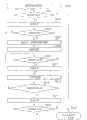
Fig. 1 is the structured flowchart of the encoding processor of the 1st execution mode.
Fig. 2 carries out the structured flowchart that coded data in the coded sequence control part of Fig. 1 is selected the part handled.
Fig. 3 is the flow chart of the encoding process step of expression the 1st execution mode.
Fig. 4 is the structured flowchart of the encoding processor of the 2nd execution mode.
Fig. 5 is a flow chart of representing the processing of the 2nd execution mode simplifiedly.
Fig. 6 is the data flow of coding stage of initial condition of expression the 2nd execution mode and the figure of memory content.
Fig. 7 is the figure of coding, the data flow when coding stage begins again and the memory content of expression the 2nd execution mode.
Fig. 8 is the coding of expression the 2nd execution mode, the data flow when coding stage finishes again and the figure of memory content.
Fig. 9 is the data flow of transfer phase of expression the 2nd execution mode and the figure of memory content.
Figure 10 is the data flow of coding stage behind the transfer phase of expression the 2nd execution mode and the figure of memory content.
Figure 11 is the detailed flow chart of the processing of expression the 2nd execution mode.
Figure 12 is the figure of an example of transition of value of the 1st counter of expression the 2nd execution mode.
Figure 13 is the structured flowchart of the encoding section again of the 2nd execution mode.
Figure 14 is the structured flowchart of variation of the encoding processor of expression the 2nd execution mode.
Figure 15 is the coding of the structure of expression Figure 14, the data flow the during beginning of coding stage and the figure of memory content again.
Figure 16 is the coding of the structure of expression Figure 14, the data flow the during beginning of coding stage and the figure of memory content again.
Figure 17 is the data flow of transfer phase of structure of expression Figure 14 and the figure of memory content.
The figure of the boundary condition when Figure 18 is a side who is used for illustrating in execution mode selection lossless coding data and the lossy coding data.
The figure of the boundary condition when Figure 19 is a side who is used for illustrating in execution mode selection lossless coding data and the lossy coding data.
Figure 20 is the figure of expression sample (sample) original image.
Figure 21 is the figure that is illustrated in the quantization matrix table that uses in the execution mode.
Figure 22 is the structure chart of the photocopier that is suitable for of execution mode.
Embodiment
Below, describe embodiments of the present invention with reference to the accompanying drawings in detail.
The explanation of<device summary 〉
Figure 22 is the structured flowchart of the photocopier that is suitable for of execution mode.
In Figure 22, the 1st, the control part of the control of the whole device of department's palm is made of CPU, ROM, RAM etc.The 2nd, the operating portion that constitutes by LCD display, various switch, button etc.The 3rd, manuscript reading section (image analyzer portion) is equipped with ADF (Auto DocumentFeeder).The image that has read is by each colour content of RGB, as the numerical data output of 8 (256 GTGs).The 4th, according to the print data of the PDL form that receives via not shown interface (comprising network interface), describe (rendering) portion of describing of print image.The 5th, any one from the bitmap images of manuscript reading section 3 or drawing section 4 outputs according to the indication from control part 1, selected, exported to selector.
The 6th, as the encoding processor of the characteristic of present embodiment.This encoding processor 6 is used for the coding of view data, and its detailed content is with aftermentioned.
7 is No. 2 storage devices (being hard disk unit in the execution mode), stores the coded data by encoding processor 6 outputs in order.
The 8th, decoding processing portion, to be stored in No. 2 storage devices 7, be compressed the view data of having encoded, read, decode by its storage order.The 9th, image processing part, input is as the YMC that writes down the color space from the decoded picture of decoding processing portion 8 with the RGB color space transformation, carries out UCR (Under Color Removal) and handles, and carry out the treatment for correcting of view data.
The 10th, Printer Engine portion.The printing mechanism of Printer Engine portion is the laser beam printer engine herein, but also can be the type of discharging black liquid, and is not limited to kind.
In said structure, for example, in user's operating operation portion 2, select copy mode, original copy is arranged at manuscript reading section 3 (ADF of manuscript reading section 3), press when duplicating initiating key, the original image data that read by manuscript reading section 3, by raster order, be transferred into encoding processor 6 via selector 5, store storage device 7 successively into No. 2 times after being compressed coding here.
In addition, receiving under the situation of print data, making selector 5 select drawing sections 4, the image of the print data that generates based on drawing section 4 is being carried out compressed encoding, storing storage device 7 into No. 2 times by the outside.
Compress coding data according to the print speed of Printer Engine 10, is read from No. 2 storage devices 7 by decoding processing portion 8, carries out decoding processing.Then, from by image processing part 9 decoded image data, generate the record view data of YMCK composition.Then, export this result to Printer Engine portion 10, print.
As described above, store compress coding data the stores processor of No. 2 storage devices 7 into, it is asynchronous handling with reading of being used to decode, print.Promptly, become storage device 7 No. 2 times, as playing a role with the buffer between the decoding processing between image Compression, because original copy reads/encoding process, do not rely on decoding/recording processing, therefore can read a large amount of original copys at high speed, the original copy that can carry out the transition to next operation rapidly reads.
More than, the structure of whole device in the execution mode is illustrated.Then, the encoding processor 6 as the characteristic of this device is described.
The explanation of<encoding section 〉
Fig. 1 is the structured flowchart of the encoding processor 6 of execution mode.
The 1st encoding section 102 is lossy coding portions, according to the parameter that influences compression ratio, the block of pixels unit by input part 101 inputs is carried out compressed encoding handle, and exports its result (coded data).In coded data foremost, additional representation has been carried out the sign position of coding by the 1st encoding section 102.
As this image encoding portion 102 in the execution mode, the example that has been suitable for JPEG coding (not lossless coding) is described.That is, the view data that is equivalent to 8 * 8 pixel units is carried out Direct Transform, use quantization step described later to quantize, carry out huffman coding and handle.Decision is a quantization step the sign indicating number amount of this generation, and this quantization step is set by coded sequence control part 110.The JPEG coding is widely known by the people as the technology that is suitable for natural image.
Quantization matrix table Q0, Q1, Q2 (being stored in the coded sequence control part 110) that Figure 21 uses when being illustrated in the coefficient of frequency that quantizes behind the dct transform.Herein, the value Qi (0,0) in the quantization matrix table~Qi (7,7) (i=0,1,2...) expression quantization step value.The quantization step value roughly is in the relation of Q0<Q1<Q2....Along with the quantization step value becomes big more, the scope that the coefficient of frequency value after the quantification can be got becomes narrow more, and compression ratio is improved.
The 2nd encoding section 103, different with the 1st encoding section 102, be lossless coding portion.Owing to be lossless coding portion, thus its decoded result become with encode before image identical, do not produce the deterioration of image quality on the principle.Do not influence the setting of the parameter of compression ratio yet.In execution mode, in the 2nd encoding section 103, adopted JPEG-LS.Though JPEG-LS is titled with " JPEG ", its algorithm is different fully with the lossy coding JPEG that adopts in the 1st encoding section.The feature of JPEG-LS coding, it is the technology that is suitable for character string diagram, computer graphics (computer graphics), under the situation that is these images, give quantization step as the JPEG of lossy coding, can generate than " 1 " (harmless in fact) in addition in " 2 ", " 3 " etc. the coded data of the coded data much less during smaller quantization step value.
In addition, the 2nd encoding section 103, with the identical in fact timing of the 1st encoding section 102, identical block of pixels is encoded outputting encoded data.And, the 2nd encoding section 103, when outputting encoded data, in this coded data foremost, additional representation has been carried out the sign position of coding by the 2nd encoding section 103.
The 1st code length test section 108 detects from the coded data long (comprising 1 as the sign position) of the block of pixels of the 1st encoding section 102 outputs, exports coded sequence control part 110 to.The 2nd code length test section 109 detects from the coded data long (comprising 1 as the sign position) of the block of pixels of the 2nd encoding section 103 outputs, exports coded sequence control part 110 to.
Coded sequence control part 110, the control of the encoding processor 6 of department's palm execution mode.As 1 of its processing, use is from the signal of the 1st code length test section the 108, the 2nd code length test section 109, and built-in LUT (table of comparisons) 120, determines to be stored to the coded data (it selects principle with aftermentioned) of the 1st memory 105.Then, will be used to select the selection signal of this coded data of determining to export the 1st memory controller 104 to.
And coded sequence control part 110 possesses the 1st counter 111 that the code length data that will be stored in the coded data in the 1st memory 105 is carried out stored counts.The 1st counter 111, corresponding with object block, and the coded data that accumulative total will be stored in the 1st memory 105 is long, therefore preserves the information that expression has been stored in the total coded data amount in the 1st memory 105.
And, above-mentioned coded sequence control part 110, value (being stored in the amount of coded data in the 1st memory 105) to counter 111 compares with target data amount (be set at according to the size of input picture and determine), reach this target data amount when (exceeding desired value) detecting, to memory controller 104 output control signals, make and discard the data that the storages in the memory 105 finish, and with counter 111 zero clearings.In addition, to the input again of control part 1 (with reference to Figure 22) requested image.
So, value at counter 111 exceeds under the situation of target data amount, carry out the input again of view data, but when the input again of carrying out view data, the quantization step Qi that is set in the 1st encoding section 102 is before this changed to the Qi+1 in next stage, make after the compression ratio lifting, encode again again.
As above, become in the value of counter 111 and surpass under the state of target data amount, finish 1 page coding after, in the 1st memory 105, generate the coded data that can't harm, diminishes the page object that mixes, this is outputed to storage device 7 No. 2 times.In addition, one page view data begins the coding of one page view data (perhaps next original copy) down when (perhaps having next original copy) when existing down.
More than the general contents processing of encoding processor in the execution mode 6 is illustrated.Then, to coded sequence control part 110 in the execution mode, determine that the principle that is stored in the coded data in the 1st memory 105 describes.
In execution mode, the JPEG that the 1st encoding section 102 is utilized as lossy coding, the situation that the 2nd encoding section 103 is utilized as the JPEG-LS of lossless coding.JPEG is such as everyone knows, is the coding techniques that is suitable for the compression of natural image, but not high to the compression ratio of character string diagram etc.On the other hand, JPEG-LS is suitable for character string diagram (comprising color) and dull CG images such as string diagram, and, owing to be the cause of lossless coding, image deterioration does not take place on the principle.But JPEG-LS is not high to the compression ratio of natural image.That is, these 2 kinds of coding techniquess are in complementary relationship.
, the situation that reads original copy is as shown in Figure 20 investigated, this original copy comprises character lines graph region T1, T2, based on gray scale (gradation) (image that concentration changes smoothly) the regional G and the natural image area I of computer graphics herein.
Suppose in character lines graph region T1, only have the steep character string diagram of edge of image, and in character string diagram T2, only have some fuzzy character string diagram of marginal portion.Character lines graph region T2 has been equivalent to impose the situation that digital resolution conversion was handled or carried out to reverse sawtooth (Anti Alias) that the limit that is used to make character, figure seems level and smooth.
So, read illustrated original copy, if carrying out the code length of the coded data of lossless coding acquisition by 8 * 8 block of pixels units is Lx, if encoding afterwards to same block of pixels with lossy coding (quantization step Q0), the code length of the coded data of acquisition is Ly, expression is to Lx, Ly being some P (Lx, the result who Ly) draws of coordinate in Figure 18.
The general partitioned area of point of the drafting of above-mentioned each regional T1, T2, G, I is represented in each distributed areas 2001 to 2005 that fences up with ellipse in Figure 18.In addition, though also drawn oval outside, graphical pointv like this is few, thereby is ignored as irregular point.And illustrated dotted line 2006 is straight lines of expression Ly=Lx relation.
,, store the coded data of the 1st memory 105 into herein, can determine with following such condition if from the viewpoint of the compression efficiency of coded data.
1. when being in the concerning of Ly<Lx, will be from lossy coding storage to the 1 memory 105 of the 1st encoding section 102.
2. when being in the concerning of Ly 〉=Lx, will be from lossless coding storage to the 1 memory 105 of the 2nd encoding section 103.
Do like this by above, can make total coded data quantitative change of 1 page of the 1st memory 105 become minimum data amount.
But, under the situation of boundary condition Ly=Lx, becoming computer gray areas G is cut apart by border 2006, formation diminishes coded data and lossless coding data and is present in state in the block of pixels unit jointly, according to circumstances may cause alternately generating the block of pixels of the block of pixels of lossless coding data with the lossy coding data.If this is decoded, can produce the discontinuous mosaic noise in the border that makes block of pixels (block noise), aspect image quality, go wrong.
Therefore, in execution mode, set with the nonlinear boundary condition shown in the solid line 2007 of Figure 18.Promptly, set distributed areas 2003 by computer gray areas G, centre position with the distributed areas 2004 of natural image area I, protrude the curve of (to being recessed on) downwards in the modes outside distributed areas 2003, and, make between the distributed areas 2004 of its distributed areas 2002 of passing through character lines graph region T2 and natural image area I.
In addition, the sweep of boundary line 2007 among Figure 18 is expressed as by between computer gray areas G and the natural image area I, but is not to pass through outside the computer gray areas G, and preferably uses more model to obtain.In a word, to comparing with simple linear barrier's condition 2006, the lower part of sign indicating number amount as the boundary line 2007 of implementing mode adopts the probability of lossless coding data to uprise, and can suppress the generation of problem as described above.And, because the boundary line becomes the little zone of code length that nonlinear position is two kinds of codings, therefore can also reduce the influence that brings to the amount of coded data of entire image.
Herein, will be with the boundary condition of solid line 2007 expression, when being expressed as Ly=f (Lx),
1. when being in the concerning of Ly<f (Lx), will be from lossy coding storage to the 1 memory 105 of the 1st encoding section 102.
2. when being in the concerning of Ly 〉=f (Lx), will be from lossless coding storage to the 1 memory 105 of the 2nd encoding section 103.
As a result, in the computer gray areas, the probability step-down that the coded data of different coding kinds mixes can suppress the generation of above such problem.In addition, in Figure 18, than an A (
The bigger zone of code length of the maximum that the lossless coding data of computer gray areas are long+α) represents with straight line, but also can make it constitute along distributed areas 2002 curve, more than or equal to pre-regularly with the straight line definition of Ly=Lx.
By above-mentioned execution mode, when the value of the 1st counter 111 exceeds the target data amount, the quantization matrix table that is set in the 1st encoding section 102 is changed to Q1 from Q0, carry out the input again of image.That is, in the encoding process of the 2nd view data (perhaps the 2nd original copy reads), it is big that the quantization step value during coding becomes, and therefore the amount of coded data that is generated by the 1st encoding section 102 becomes and lacks than the 1st time.
Consequently, move towards little direction for the longitudinal axis integral body distributed areas 2001 to 2004 of Figure 18, and, become state reduced on the longitudinal axis, become distributed areas shown in Figure 19 2001 ' to 2004 ' appearance.In addition, boundary condition 2007 " of this moment need more approaching simple comparison, and curve direction down moves.In same target, allow coded system to mix thus, compare in the time of can not denying with the 1st coding and can cause the image quality deterioration, but harmless coded system is preferentially selected, therefore lossless coding piece in the selection memory more.
If the processing with regard to the coded sequence control part 110 in execution mode of above explanation is summarized, then as follows.
The quantization matrix table that is set in the 1st encoding section 102 is made as Qi, boundary condition function at this moment is made as Ly=f
i(Lx).
1. be in Ly<f
iDuring concerning (Lx), the signal from the lossy coding data of the 1st encoding section 102 with selecting to be stored in the 1st memory 105 exports the 1st memory controller 104 to.
2. be in Ly 〉=f
iDuring concerning (Lx), the signal from the lossless coding data of the 2nd encoding section 103 with selecting to be stored in the 1st memory 105 exports the 1st memory controller 104 to.
Also can be at the coded sequence control part 110 that is used for realizing above-mentioned processing, built-in function f
i() compares computing at every turn, but oversimplifies in order to make to handle, and makes its built-in LUT (table of comparisons) 120.
With used coded sequence control part 110 in the selection relevant structure of coded data of LUT120, for example can be by structure realization shown in Figure 2.
Provide following information to LUT120: from the code length data of the 1st code length test section 108 as the address; Code length data from the 2nd code length test section 109; And the quantization matrix table numbering i that is used to determine be set in the quantization matrix table Qi of the 1st encoding section 102.This quantization matrix table numbering i also can be considered as being used to select a plurality of boundary condition function f
iThe signal of table.
The signal of 1 (bit) is stored to the interior above-mentioned address location of LUT120 in advance.For example, be in Ly 〉=f
iThe address location storage 1 of relation (Lx); Be in Ly<f
iThe address location storage 0 of relation (Lx).
Then, when addressing, signal is selected as coded data in the position of this signal, export the 1st memory controller 104 to.And this coded data is selected signal, also is provided as the selection signal of selector 121.Then, 121 pairs of selected code length data of selector are selected, and make the 1st counter 111 carry out accumulation calculating.
In order to realize above-mentioned processing, coded sequence control part 110 can be handled according to the flow chart of Fig. 3.
At first, in step S1, give variable i as initial value with 0.Then, in step S2, will be equivalent to the variable Cn zero clearing of the 1st counter 111.
Afterwards, in step S3, quantization matrix table Qi is arranged at the 1st encoding section 102, the data of input 1 block of pixels in step S4.Then, in step S5, carry out lossless coding, in step S6, obtain the long Lx of coded data that obtained this moment by the 2nd encoding section 103.And, therewith abreast, in step S7, S8, carry out lossy coding, obtain the code length Ly of the coded data that is obtained this moment.
In addition, in diagram, represented the parallel example that carries out of step S5, S6, but, can handle equally under the situation about realizing and under the situation of operation multitask OS by computer program with step S7, S8.And under situation about realizing by single task OS, should only needing set by step, the sequential processes of S5, S6, S7, S8 gets final product.
In step S9, judge whether to satisfy Ly 〉=f
i(Lx).Satisfying under the situation of this relation, in step S10, making the 1st memory stores lossless coding data.Then, in step S11, on count value Cn, add code length Lx.
On the other hand, in step S9, be judged as Ly<f
i(Lx) time, in step S12, make the 1st memory stores lossy coding data.Then, in step S13, on count value Cn, add code length Ly.
Then, enter step S14, judge whether 1 page encoding process finishes.Whether this judgement has reached total block of pixels number of 1 page by the block of pixels number of judging input gets final product.
When in this step S14, being judged as when not finishing, enter step S15, whether the value of judging count value Cn has reached the threshold value T more than or equal to expression target data amount.For not the time,, therefore return step S4 in the result owing to will import next block of pixels.
In addition,, enter step S16, make variable " i " increase " 1 " being judged as count value Cn when having become more than or equal to threshold value T and since will from page or leaf begin input picture once more foremost, therefore return step S2.
On the other hand, when the encoding process that is judged as 1 page in step S14 has been finished, enter step S17, carry out outputing to the processing of the 2nd storage device 7 being stored in coded data in the 1st memory 105.
As mentioned above,, special image-region decision circuitry is not set according to present embodiment, just can generate with on one side and with lossless coding, lossy coding, on one side generate the coded data of the encoding process equivalence suitable with pressing each image-region execution.And, exceeding under the target code data conditions, by change quantization matrix table, carry out the input again of view data, encode again, also can generate the coded data that is less than or equal to the target data amount.
The explanation of<the 2 execution mode 〉
In above-mentioned execution mode (the 1st execution mode), in carrying out 1 page the process of coding, when the amount of coded data that is generated surpasses destination number, import once more.
In this 2nd execution mode, the input again of the image that does not carry out 1 page is described, and generates the example of the coded data that is less than or equal to the target data amount.
Apparatus structure is identical with Figure 22, below emphatically encoding processor 6 is described.
Fig. 4 is the structured flowchart of the encoding processor 6 of the 2nd execution mode.With the difference of Fig. 1, be to have added the 2nd memory controller the 106, the 2nd memory 107, encoding section 112 and the 2nd counter 113 again.Identical with Fig. 1 except that these, therefore give identical label.
And in the 1st memory 105, therefore storage omits the explanation to it according to the selected coded data of judgment standard same with the 1st execution mode that illustrates previously.Below, the feature of this 2nd execution mode is described.
The 2nd memory controller 106, under the control of coded sequence control part 110, the coded data of carrying out being generated by the 2nd encoding section 103 stores the stores processor of the 2nd memory 107 into; And read coded data by the 2nd memory 107.The 2nd memory 107, the operating area when 1 page view data is encoded and using.
Store the lossless coding data by the 2nd encoding section (LPEG-LS encoding section) 103 codings in the 2nd memory 107, therefore, at first by LPEG-LS lsb decoder 112a, decoding (recovery) is the block of pixels of original image.Then, JPEG encoding section 112b, the block of pixels that will be restored is carried out JPEG coding (lossy coding) according to the quantization matrix table Qi that is set by coded sequence control part 110.At this moment, in coded data foremost, this is the sign position of lossy coding data for an additional representation.
Code length test section 112c detects the code length of the coded data of being encoded by JPEG, and code length test section 112d detects the code length of the lossless coding data of being read by the 2nd memory.The identical information of LUT120 in LUT112e storage and the coded sequence control part 110, the quantization matrix table numbering i of own coding sequence control part 110 imports as the address with 2 code length data in the future, and 1 signal is exported as the selection signal.
At carrying out above-mentioned processing repeatedly by coded sequence control part 106 specified scopes.The 2nd counter 113, encoding section 112 again coding begins again the time be reset, the amount of coded data that generates by encoding section 112 is again carried out accumulated counts.When finishing the coding again of the scope that sets, the value (by the amount of coded data of encoding and generating again) that is kept in the 2nd counter is output to coded sequence control part 110.
More than, be illustrated at the structure of Fig. 4, below, the processing of integral body is described in detail.
When the coding of the view data that begins one page, will be set to coded sequence control part 110 corresponding to the target data amount of the picture size of being imported by control part 1.110 pairs the 1st encoding section of coded sequence control part 102 are set the initial quantization matrix table Q0 coding parameter of high image quality (), with 111 zero clearings of the 1st counter.Then, make the 1st encoding section the 102, the 2nd encoding section 103 beginning encoding process.Below, be 1 page the input of view data and the explanation of encoding process.
By the 1st encoding section 102 and the 2nd encoding section 103, export coded data, and, detect code length separately by the 1st, the 2nd code length test section 108,109 for the same pixel piece, export this detected code length.Coded sequence control part 110, with the 1st execution mode similarly, promptly according to the structure of Fig. 2, select the coded data of any one, make the 1st counter 111 add the code length information of the coded data of this selection.What at this moment, expression is selected is which side control signal outputs to the 1st storage control part 104.
The 1st memory controller 104 is accepted above-mentioned control signal from coded sequence control part 110, selects code length to be judged as short coded data, stores the 1st memory 105 into.Above result is that the short coded data of the code length aspect each block of pixels of view data is stored in the 1st memory 105 in turn.That is, lossless coding data and lossy coding data mix and are stored in turn in the 1st memory 105.On the other hand, only the lossless coding data are stored in the 2nd memory 107 in turn.
It should be noted that the information that in the 1st counter 111, stores the total yard amount that is stored in the coded data in the 1st memory 105 herein.
Hereto, remove and in the 2nd memory 107, store outside the lossless coding data, identical with the 1st execution mode.
Coded sequence control part 110, the supervision encoding process is carried out the value of the 1st counter 111 in the process, promptly is stored in the total amount of the coded data in the 1st memory 105, judges whether to exceed (also comprising arrival) target data amount.Then, be judged as the value (total sign indicating number amount) that is stored in the 1st counter 111, when exceeding the target data amount, coded sequence control part 110 carries out following step.
Step 1). to the 1st memory controller 104 output control signals, the data of having stored in feasible discarded the 1st memory 105.The 1st memory controller 104 according to this control signal, by emptying memory address counter or emptying the coded data admin table, comes discarded coded data of having stored.
Step 2). with 111 zero clearings of the 1st counter (input from the image of input part 101 then continues)
Step 3). because for the 1st encoding section 102, need quantize matrix table so upgrade to encode than higher before compression ratio.That is, when the quantization matrix table that in the past is set up is Oi, Oi+1 is set.Owing under initial condition, be set to Q0, therefore, Q1 is set being judged as at first when exceeding aim parameter.
Step 4). with 113 zero clearings of the 2nd counter, Oi+1 is set to encoding section 112 again with the quantization matrix table, begins to be stored in the coding again of the coded data of the 2nd memory 107.The coded data of coding back acquisition (harmless, lossy coding data mix) stores the 2nd memory 107 again into again.In addition, because in the 2nd memory 107, also store coded data, so both differentiate and store from the 2nd encoding section 103.
Step 5). when coding is finished again, will " again " store the coded data in the 2nd memory 107 into, be sent to the 1st memory 105, and delete the coded data (coded data from encoding section 103 is not deleted) that the back of coding again in the 2nd memory 107 obtains.And the value of reading the 2nd counter 113 is added on the 1st counter 111.Consequently become the 1st counter 111 and represent to be stored in the total amount of the coded data in the 1st memory again.
In addition, whether the 2nd memory controller 106 detects encoding process again and finishes.That is, if the data of reading for encoding process have not more had, the end notification coded sequence control part 110 of encoding process more then.In fact, be not only the processing of reading of the 2nd memory controller 107, and after the processing of encoding section 112 also finished again, encoding process was finished.
And, before the input of 1 page image is finished with coding, be judged as total coded data amount once more when exceeding target data values, carry out above-mentioned steps 1 to step 5.Therefore, finally, storage is less than or equal to the coded data of target data amount in the 1st memory 105.
The treatment step of the coded sequence control part 110 in the structure of Fig. 4 of above explanation is expressed as the flow chart of Figure 11, simple in order to make explanation, at first, describe according to the flow chart of the Fig. 5 that has simplified.
The flow chart of Fig. 5 is if roughly distinguish, the processing stage of can being divided into following 3.
(1) coding stage
(2) coding, coding stage again
(3) transfer phase
With visual way, be illustrated in with being easily understood above-mentioned each the processing stage in, view data, coded data etc. is how to flow, and is how processed, and how to be stored in the memory be Fig. 6 to Figure 10.
Fig. 6 represents that step S303 in the flow chart with Fig. 5 is with the initial condition in S305 corresponding codes stage.In addition, the switch 40 among Fig. 6 is for the function by coded sequence control part 110 and the 1st memory controller 104 realizes.The signal that is used to switch is used to the signal from LUT120 shown in Figure 2.
Any one that the 1st memory 105 is stored in the coded data that is generated by 2 encoding section.Therefore, keep such relation: be stored in the data volume I in the 1st memory 105, lack than the data volume I ' that is stored in the 2nd memory 107.
Fig. 7 is illustrated in the state when having changed the quantization matrix table among the step S309.Such as shown, there is not coded data in the 1st memory 105.
Fig. 8 represents and step S311~S315 corresponding codes, the treatment state of coding stage again that Fig. 9 represents the treatment state of the transfer phase corresponding with step S317, and Figure 10 represents the treatment state of the coding stage behind the transfer phase.Below, each stage is described.
" coding stage "
The encoding process of the view data of 1 page of amount is handled (step S301) from the initial setting of coding parameter.At this, be following processing: set dimension of picture from encoding process
The target data amount of the amount of coded data that (page or leaf is recorded and narrated and to be described to wait the paper size that reads from input part 101) determined uniquely, be applicable to the quantization matrix table Q0 of the 1st encoding section 102.
Afterwards, in step S303, by the 1st encoding section 102 and the 2nd encoding section 103 beginning encoding process.Consequently in the 1st memory 105, block unit is according to pixels stored in turn from the coded data of the 1st encoding section 102 with from the coded data of the 2nd encoding section 103 any one.Be stored in the amount of coded data in the 1st memory 105, count this point by the 1st counter, with set forth identical.On the other hand, in the 2nd memory 106, storage is from the coded data of the 2nd encoding section 103.Fig. 6 represents this situation.Expression is stored in the area I of the data volume in the 1st memory 105, be less than or equal at least the area I that expression is stored in the data volume in the 2nd memory 107 '.
Then in step S305, whether the count value that detects this data volume exceeds above-mentioned desired value, if do not exceed, then continues the 1st coding and the 2nd encoding process of step S303.This is the coding stage of initial condition.
" coding, coding stage " again
Proceed in encoding process, when the total coded data amount in the 1st memory of being stored in exceeds aim parameter, the coded data in step S307 in discarded the 1st memory 105, and in step S309, to be set in the quantization matrix table Q0 of the 1st encoding section 102, be updated to the Q1 of next stage.Total coded data amount exceeds the target data amount, and the data volume after the expression compression can't be accommodated in the target.Thus, it is nonsensical to re-use identical quantization step continuation encoding process, therefore, just changes to the quantization step Q1 bigger than former quantization step width.
After having changed quantization step, in step S311, carry out the encoding process of the 1st encoding section 102 and the 2nd encoding section 103 again.And, with quantization matrix table Q1 (with quantization matrix epiphase after the renewal that is set to the 1st encoding section with) be set to again encoding section 112, begin to be stored in the coding again of the amount of coded data of the 2nd memory, coding result stores the 2nd memory again into again.That represent this state is Fig. 7.
In step S315, wait for then until again till the finishing dealing with of coding.
<transfer phase 〉
Expression is encoded when having finished when being judged as in step S315 again, the memory state of the coded data of the 1st memory 105 and the 2nd memory 107 be Fig. 8.In Fig. 8, area I I, II ' are illustrated in the process of carrying out again encoding process, with the view data corresponding codes data of new input, area I represent to be stored in area I ' in the coding result again (lossy coding data and lossless coding data mix) of coded data.
In step S317, as shown in Figure 9, the coded data again (illustrated area I) that is stored in the 2nd memory 107 is sent to the 1st memory 105.After this transmission is finished, the data (perhaps allowing to write covering) of the area I in discarded the 2nd memory 107.
After above-mentioned transfer phase finishes, return the coding stage of step S303, S305, return coding stage.Consequently as shown in Figure 10, carry out and coded data III, the III ' of new input image data to be stored into the stores processor of memory separately.This coding stage, have different slightly with the coding stage (Fig. 6) of initial condition, this difference is, the quantization step during by the 1st encoding section 102 codings changes to Q1 from Q0, and the order that is stored in the coded data in the 1st memory 105 is not the image input sequence.If ignore these differences, the coding stage of back to back coding stage and initial condition can be considered identical behind the transfer phase.In addition, as shown in Figure 10, the order of coded data is not one to be decided to be time series, can be with the memory address storage in advance separately in each stage yet, finish when outputing to No. 2 storage devices 71 page encoding process, read the coded data line output of going forward side by side by the time sequence from the 1st memory 105.
Therefore, by the repeated encoding stage, coding, coding stage and these 3 stages of transfer phase again, can be finally 1 page Image Data Compression be stored in the 1st memory 105 at the sign indicating number that is less than or equal to the data volume set point.And input part 101 just continues input till a series of finishing dealing with.That is, do not need again image is re-entered from beginning at first.
Flow chart shown in Figure 5 been has only has been recorded and narrated the extremely corresponding processing of each stage shown in Figure 10 with Fig. 6, so that explanation is easier to understand.But the in fact input of 1 page view data can finish in certain stage.Therefore, according to being in which stage end, also what exist different the correspondence after this.The expression considered these flow process be the flow chart of Figure 11.The flow chart of Figure 11 has considered that the input of the view data of 1 page of amount is finished and the relation between various processing illustrated in fig. 5, and this is on the flow chart of Fig. 5, appends S801, S803, S805, S807 in steps.
Whether step S801, S803, S805 respectively in coding stage, coding, coding stage, and transfer phase again, finish to detect to the input from the view data of 1 page of amount of input part 101.
When the input that detects the view data of 1 page of amount at coding stage and transfer phase has finished (step S801, S805), transfer to step S807, finishing the compressed encoding of this page handles, if there is next view data more than 1 page or 1 page to be processed, the compressed encoding that begins the view data of following 1 page of amount is handled, if not then enter halted state.
On the other hand, when at coding, when coding stage detects the end of input of view data of 1 page of amount again (step S803), need supspend action, until till the view data of encoding process is handled again in the 1st encoding section the 102, the 2nd encoding section 103.Therefore, skip the encoding process of (pass) step S311, in step S313, the view data of only proceeding to be used for to have been finished by the 1st encoding section the 102, the 2nd encoding section 103 codings up to now is controlled at the encoding process again of predetermined amount of coded data.Be all in encoding process again, transmission is afterwards handled when not finishing, because the coded data of all images data of 1 page of amount, do not focus on the 1st memory, therefore behind the end of input of the view data of 1 page of amount, also need to proceed again encoding process and then again the transmission of encoding process handle.In this case, in step S315, when detecting when encoding process is all over, in coding, coding stage again, coded data in will only being stored in the 2nd memory 107 has been sent to the 1st memory (step S317) afterwards, in following step S805, detect the end of input of the view data of 1 page of amount, transfer to step S807.
More than being the action of execution mode, also is the action specification of Figure 11.
As described above, according to this 2nd execution mode, can reach effect and the effect same with the 1st execution mode.And, need not to interrupt 1 page image input, and need not import again, also can generate the coded data that is less than or equal to the target code data volume.
What special hope aroused attention is the JPEG that has used lossy coding in the lump, these two kinds of technology of JPEG-LS of lossless coding.Such as already explained, the JPEG coding is to the compression efficiency height of natural image; The JPEG-LS coding can obtain high compression ratio to the character string diagram, because be the cause of lossless coding, can verily reproduce original image.
Herein, the example with the transition of the time shaft of the 1st counter 111 (sign indicating number amount) is expressed as Figure 12.
Figure 12 represents to begin with timing T0 the input of original image, has finished the situation of the input of original image with timing T5.If the size of the original copy of being imported is fixed, regularly T5 then becomes fixing.Below, each processing regularly is described.
Timing T0:
Be that the image input begins (coding beginning) regularly.At this moment, to the 1st encoding section 102 quantization matrix table Q0 is set as initial value, the 1st counter 111 is initialized to " 0 ".Afterwards, when input that continues image and coding, carry out the coding of the coded data of view data, the count value of the 1st counter 111 increases gradually.
Timing T1:
The amount of coded data of presentation video data has arrived the situation of object code amount.At this moment, the coded data of the view data of discarded the 1st memory 105 with 111 zero clearings of the 1st counter, is updated to Q1 with the quantization matrix table that is arranged at the 1st encoding section 102.In addition, also encoding section 112 again is provided with quantization matrix table Q1, makes to begin encoding process again.
Timing T2:
Expression is encoded and is transmitted finishing of processing.When coding was finished again, the coded data of coding back acquisition was sent to the 1st memory 105 from the 2nd memory 107 again, and represents the value of the 2nd counter 113 of amount of coded data again, is added on the 1st counter 111.Consequently in the 1st memory 105 and the 2nd memory 107, storage with quantization matrix table Q1, to since 1 page foremost to the encode coded data of back equivalence of the view data of importing the timing T2.
Timing T3:
The amount of coded data of presentation video data has arrived the situation of object code amount once more.At this moment, the coded data of the view data of discarded the 1st memory 105, with 111 zero clearings of the 1st counter, the quantization matrix table that is arranged at the 1st encoding section 102 is set to Q2.In addition, also encoding section 112 again is provided with quantization matrix table Q2, making again, encoding process begins.
Timing T4:
Expression is encoded and is transmitted finishing of processing.When coding was finished again, the coded data of coding back acquisition was sent to the 1st memory 105 from the 2nd memory 107 again, and represents that again the value of the 2nd counter 113 of amount of coded data is added on the 1st counter 111.Consequently in the 1st memory 105 and the 2nd memory 107, storage with quantization matrix table Q2 to since 1 page foremost to the view data of importing the timing T2 equivalent coded data in back of encoding.
Timing T5:
Represent 1 page the finishing of original copy input.At this moment, in the 1st memory 105, store the coded data of 1 page image, therefore, its result is outputed to storage device 7 No. 2 times.
Reading under the 2nd page the situation of original image, repeat the processing that begins from above-mentioned timing T0 herein.
In addition, according to different images, sometimes also may be before the timing T5 of the input that is about to finish original image, the value of the 1st counter 111 exceeds aim parameter.In this case, after timing T5, encode again and transmit processing.Therefore, be stored in the condition that coded data in the 1st memory 105 is input to No. 2 storage devices 7, for the input of having finished original image and finished the situation of coding (encode again and transmit).
The variation 1 of<the 2 execution mode 〉
Figure 14 is the variation at Fig. 4.With the difference of Fig. 4, be that by encode the again storage purpose ground of the coded data that the back obtains of encoding section 112 again be the 1st memory 105.In addition structure is identical with Fig. 4.
Total coded data amount that Figure 15 represents to be stored in the 1st memory 105 exceeds target data, the data in discarded the 1st memory 105, the state when beginning to be stored in the encoding again of coded data (illustrated area I ') in the 2nd memory 107.
Like that, the storage purpose ground of the coding again of encoding section 112 again is set at the 1st memory 105 as shown, making again, coding begins.
Figure 16 has represented to finish the store status of the coded data of 2 memories when encoding again.Finishing when encoding again, such as shown, in the 1st memory 105, store the coded data of representing with area I.The coded data of this area I, be equivalent to quantization matrix table Q1 to judge the target data amount exceeded before till the view data of input carried out the situation of coding.
Because even carrying out in the process of encoding again, the input of view data and coding are also carrying out, thus such as shown, there are area I I, II '.
Because in the 1st memory 105, generating has dummy section 105a, therefore makes the coded data of area I I shown in Figure 16 move to the back-end location of area I.Afterwards, become again and carry out coding stage, this moment, the store status to memory was shown in Figure 17.
The advantage of the structure of the Figure 14 for Fig. 4, the data that have been to eliminate in fact after encoding again transmit.
In addition, owing in this variation, just eliminated transfer phase, therefore above-mentioned the 2nd execution mode and this variation are handled in 3 stages of repetition and are not changed.Thereby, the content of processing also with Fig. 5, Figure 11 much at one, do not need to describe.In addition, carried out moving in the 1st memory 105 in order to eliminate dummy section 105a in Figure 16, but the file management table of each regional annexation of management also can be set, perhaps therefore grouping management table etc., is not certain inner transmission that need.
The variation 2 of<the 2 execution mode 〉
In the variation 1 of above-mentioned the 2nd execution mode and the 2nd execution mode, when the amount of coded data in the 1st memory 105 exceeds the target data amount, carried out coding again by the coded data of 112 pairs the 2nd memories 107 of encoding section again.In other words, then for not carrying out during the amount of coded data miss the mark data volume of encoding section 112 in the 1st memory 105 again.
Therefore, will effectively utilize the example during this to describe as variation 2.
Below, be the situation of the amount of coded data miss the mark data volume in the 1st memory 105, it should be noted that the explanation of the lossless coding data from the 2nd encoding section 103 being stored in turn into the processing in the process of the 2nd memory 107.In addition, as condition, be that Qi describes with the quantization matrix table that is set in the 1st encoding section 102.
, identical from the 2nd encoding section 103 with the 2nd execution mode to the 2nd memory 107 storage lossless coding data.But encoding section 112 advances to the front with following processing and carries out again, and this is treated to: read successively from the lossless coding data of being stored, utilize to quantize matrix table Qi+1 and encodes, generate the lossy coding data, store its result into the 2nd memory 107.
Consequently when the coded data in the 1st memory 105 has exceeded the target data amount, have the lossless coding data in the 2nd memory 107, there are lossy coding data to a certain degree in certain and assurance.Therefore, if same block of pixels position, just that code length is a little side is sent to the 1st memory, and only to not existing the block of pixels that becomes the lossy coding of comparison other data to carry out getting final product based on the processing of Figure 13.
In addition, finish from the 2nd memory 107 during to the transmission of the 1st memory 105, the discarded lossy coding data that have been stored in the 2nd memory are this time set and are quantized matrix table Qi+2, and beginning coding again gets final product.Above result can further shorten and the relevant processing of coding again.
More than, the 1st, the 2nd execution mode and variation thereof of the present invention has been described.In addition, in the 2nd execution mode, be that memory separately is illustrated physically with the 1st memory the 105, the 2nd memory 107.In the present invention, these memories are set independently, are enough to constitute 1 feature.But, these memories are not set at the situation of the memory that separates physically, be also contained in the category of the present invention.Especially under the sufficiently high situation of transfer rate of memory, on 1 memory physically, guarantee to be equivalent to 2 zones of the 1st memory, the 2nd memory, the 1st memory is renamed as the 1st memory area, the 2nd memory is renamed as the 2nd memory area, utilize above-mentioned explanation to learn, also can realize the present invention by 1 memory.
And, realizing that with 1 memory under the situation of the respective embodiments described above, some part in the data transfer process that illustrates just no longer needs in above-mentioned transfer phase.Its detailed content because all easy in each case imagination obtains, is therefore omitted the explanation to it.Distinguishing closely under the situation about using in above-mentioned 2 zones, similarly need to carry out data transfer process during with 2 memories having physically, if but become 2 interregional total identical data, just not only no longer need data transfer process, and can also seek to cut down memory capacity.
For example, when the coded data of preserving in the 2nd memory area is sent to the 1st memory area, only need just can obtain and transmit the same effect of above-mentioned coded data by transmitting address foremost and these 2 information of data size that store this coded data to the 1st memory controller from the 2nd memory controller.
Storing with file format, packet format under the situation of above-mentioned coded data, needing to increase a little information that between memory controller, transmits, and needing to transmit the admin table information that is associated with this coded data.
In addition, in execution mode, coded object is illustrated as 8 * 8 block of pixels sizes, but the present invention is not subjected to the restriction of this size.In a word, only need to use 2 kinds of (perhaps also can be more than 2 kinds) different coding techniquess, relatively 2 kinds of amount of coded data that same image-region generated are got final product.For example, as long as encode by N * M block of pixels unit in JPEG coding, JPEG-LS can just can compare 4 jpeg encoded datas and 1 JPEG-LS coded data with the block of pixels of 2N * 2M as coded object.
And, in execution mode, illustrated and used as the JPEG of lossy coding with as the JPEG-LS of lossless coding example as 2 kinds of coding techniquess.But harmless, lossy coding technology are not so limited.
By execution mode as can be known, diminish in use/lossless coding is when this has 2 kinds of coding techniquess different characteristics, as JPEG and JPEG-LS aspect two to natural image/character string diagram, and the present application will be brought into play useful effect.
The nonlinear boundary function f () of above-mentioned the 1st, the 2nd execution mode comprises curved portion, but the present invention is not limited to this, and its curved portion also can be represented with many short line segments.
In addition, in above-mentioned the 1st, the 2nd execution mode, the example that the present invention is applicable to photocopier shown in Figure 22 has been described, but obviously also can be applicable to the situation that general information processing unit such as image-input device such as image analyzer and personal computer is connected and encodes.Because in this case, only need the execution program relevant get final product with Fig. 3, Fig. 5 (perhaps Figure 11), therefore, obvious the present invention also with the computer program of being correlated with as its category.And, usually computer program is by being arranged at computer-readable storage mediums such as CDROM on this computer, computer program copy or installation (install) can be carried out in system, and therefore, obviously such computer-readable recording medium is also contained in the category of the present invention.
According to the present invention of above explanation,, also can reduce the deterioration of the image quality of decoded picture even lossless coding data and lossy coding data mix.
Under the premise without departing from the spirit and scope of the present invention, the present invention can have various execution mode, and can be understood as, and the present invention is not subjected to the qualification of specific execution mode, and its scope is defined by the appended claims.
Claims (8)
1. picture coding device, according to pixels block unit is encoded to view data, it is characterized in that, comprising:
The 1st code device, to the view data imported according to pixels block unit carry out lossy coding, generate coded data;
The 2nd code device, to the view data imported according to pixels block unit carry out lossless coding, generate coded data; And
Choice device, at the code length of establishing the coded data that is generated by above-mentioned the 2nd code device is Lx, when the code length of the coded data that is generated by above-mentioned the 1st code device is Ly, satisfy under the situation of Ly 〉=f (Lx) for predetermined nonlinear boundary function f (), select and export the coded data that is generated by above-mentioned the 2nd code device, do not satisfying under the situation of above-mentioned boundary function, selecting and exporting the coded data that is generated by above-mentioned the 1st code device
Wherein, be the code length of the coded data that generates by above-mentioned the 2nd code device with X-axis, with the X-Y coordinate space of Y-axis for the code length of the coded data that generates by above-mentioned the 1st code device in,
To encode by above-mentioned the 1st code device and above-mentioned the 2nd code device and the determined coordinate of code length Lx, the Ly (Lx of the coded data of each block of pixels of obtaining to pre-prepd character string diagram, natural image and these the three kinds of images of image with tonal gradation of concentration, when above-mentioned character string diagram, natural image when Ly) being plotted in above-mentioned X-Y coordinate space and the drawing area of image with tonal gradation of concentration are defined as T, I, G
Above-mentioned nonlinear boundary function f () has by initial point and by the curve part between drawing area G and the drawing area I with by the linear portion between drawing area T and the drawing area I.
2. picture coding device according to claim 1 is characterized in that:
The X-axis coordinate of the position that above-mentioned curve part is connected with above-mentioned linear portion is near the position of maximum of above-mentioned drawing area G.
3. picture coding device according to claim 1 is characterized in that:
The judgement of above-mentioned nonlinear boundary function f () is carried out by table of comparisons memory, and this table of comparisons memory receives code length Lx, the Ly as the address, and the data of which coded data are selected in the output expression.
4. picture coding device according to claim 1 is characterized in that:
Above-mentioned the 2nd code device is the JPEG-LS code device, and above-mentioned the 1st code device generates the JPEG code device of the different coded data of compression ratio for according to the quantization matrix table of being given.
5. picture coding device according to claim 4 is characterized in that, also comprises:
Apparatus for initializing when the coding of beginning one page, is provided with initial matrix table Q0 to above-mentioned the 1st code device;
The 1st storage device, the coded data that storage is exported by above-mentioned choice device;
Monitoring arrangement monitors the amount of coded data that has been stored in the 1st storage device;
Control device, when judging above-mentioned amount of coded data more than or equal to predetermined amount of data by this monitoring arrangement, (a) coded data in discarded above-mentioned the 1st memory, (b) with parameter from be set in above-mentioned the 1st code device before quantization matrix table Qi be updated to Qi+1.
6. picture coding device according to claim 5 is characterized in that:
Above-mentioned control device, be included in upgrade to quantize matrix table after, input image data restarts apparatus for encoding once more.
7. picture coding device according to claim 5 is characterized in that:
Also comprise
The 2nd storage device, storage is by the coded lossless coding data of above-mentioned the 2nd code device;
Re-encoding apparatus, coded data in above-mentioned the 2nd storage device is decoded, encode again according to the parameter of being given, the coded data that generation diminishes, and according to above-mentioned nonlinear boundary function f (), in the coded data after selecting to encode again and the preceding lossless coding data of encoding again any one stores above-mentioned the 1st storage device into
Wherein, above-mentioned control device, when judging the amount of coded data that is stored in the 1st storage device by above-mentioned monitoring arrangement and become more than or equal to predetermined amount of data, outside above-mentioned (a) and (b), (c) parameter Qi is set to above-mentioned re-encoding apparatus, generates the coded data that becomes more than or equal to before the above-mentioned predetermined amount of data.
8. method for encoding images, according to pixels block unit is encoded to view data, it is characterized in that, comprising:
The 1st coding step, to the view data imported according to pixels block unit carry out lossy coding, generate coded data;
The 2nd coding step, to the view data imported according to pixels block unit carry out lossless coding, generate coded data; And
Select step, at the code length of establishing the coded data that is generated by above-mentioned the 2nd coding step is Lx, when the code length of the coded data that is generated by above-mentioned the 1st coding step is Ly, satisfy under the situation of Ly 〉=f (Lx) for predetermined nonlinear boundary function f (), select and export the coded data that is generated by above-mentioned the 2nd coding step, do not satisfying under the situation of above-mentioned boundary function, selecting and exporting the coded data that is generated by above-mentioned the 1st coding step
Wherein, be the code length of the coded data that generates by above-mentioned the 2nd coding step with X-axis, with the X-Y coordinate space of Y-axis for the code length of the coded data that generates by above-mentioned the 1st coding step in,
To encode by above-mentioned the 1st coding step and above-mentioned the 2nd coding step and the determined coordinate of code length Lx, the Ly (Lx of the coded data of each block of pixels of obtaining to pre-prepd character string diagram, natural image and these the three kinds of images of image with tonal gradation of concentration, when above-mentioned character string diagram, natural image when Ly) being plotted in above-mentioned X-Y coordinate space and the drawing area of image with tonal gradation of concentration are defined as T, I, G
Above-mentioned nonlinear boundary function f () has by initial point and by the curve part between drawing area G and the drawing area I with by the linear portion between drawing area T and the drawing area I.
Applications Claiming Priority (2)
| Application Number | Priority Date | Filing Date | Title |
|---|---|---|---|
| JP261565/2004 | 2004-09-08 | ||
| JP2004261565A JP4393319B2 (en) | 2004-09-08 | 2004-09-08 | Image encoding apparatus and method, computer program, and computer-readable storage medium |
Publications (2)
| Publication Number | Publication Date |
|---|---|
| CN1747525A CN1747525A (en) | 2006-03-15 |
| CN100493133C true CN100493133C (en) | 2009-05-27 |
Family
ID=35996278
Family Applications (1)
| Application Number | Title | Priority Date | Filing Date |
|---|---|---|---|
| CNB200510098330XA Expired - Fee Related CN100493133C (en) | 2004-09-08 | 2005-09-07 | Image encoding apparatus and method |
Country Status (3)
| Country | Link |
|---|---|
| US (1) | US7627181B2 (en) |
| JP (1) | JP4393319B2 (en) |
| CN (1) | CN100493133C (en) |
Families Citing this family (20)
| Publication number | Priority date | Publication date | Assignee | Title |
|---|---|---|---|---|
| JP4693603B2 (en) * | 2004-11-15 | 2011-06-01 | キヤノン株式会社 | Image encoding apparatus, control method therefor, computer program, and computer-readable storage medium |
| US7925098B2 (en) * | 2006-03-02 | 2011-04-12 | Canon Kabushiki Kaisha | Image encoding apparatus and method with both lossy and lossless means |
| JP2008042688A (en) * | 2006-08-08 | 2008-02-21 | Canon Inc | Image processing apparatus and control method thereof, and computer program and computer readable storage medium |
| JP4795161B2 (en) * | 2006-08-08 | 2011-10-19 | キヤノン株式会社 | Image processing apparatus, control method therefor, computer program, and computer-readable storage medium |
| JP2008054210A (en) * | 2006-08-28 | 2008-03-06 | Ricoh Co Ltd | Image forming apparatus, information processing method and information processing program |
| JP4682107B2 (en) * | 2006-08-28 | 2011-05-11 | 株式会社リコー | Image forming apparatus, information processing method, and information processing program |
| US20080212130A1 (en) * | 2007-02-21 | 2008-09-04 | Samsung Electronics Co., Ltd. | Data file compression apparatus and method thereof |
| KR101375662B1 (en) * | 2007-08-06 | 2014-03-18 | 삼성전자주식회사 | Method and apparatus for image data compression |
| US8014612B2 (en) * | 2007-10-12 | 2011-09-06 | Himax Technologies Limited | Image processing device and method for compressing and decompressing images |
| JP5153676B2 (en) * | 2009-02-10 | 2013-02-27 | キヤノン株式会社 | Image processing apparatus, image processing method, program, and storage medium |
| JP5089713B2 (en) * | 2010-01-18 | 2012-12-05 | シャープ株式会社 | Image compression apparatus, compressed image output apparatus, image compression method, computer program, and recording medium |
| CN101783952A (en) * | 2010-03-01 | 2010-07-21 | 广东威创视讯科技股份有限公司 | Coding optimization method and coding optimization device for images |
| RU2609094C2 (en) * | 2011-02-10 | 2017-01-30 | Сони Корпорейшн | Device and method for image processing |
| US9185424B2 (en) | 2011-07-05 | 2015-11-10 | Qualcomm Incorporated | Image data compression |
| JP6056124B2 (en) * | 2011-09-05 | 2017-01-11 | 富士ゼロックス株式会社 | Image processing apparatus and image processing program |
| CN103369313B (en) * | 2012-03-31 | 2017-10-10 | 百度在线网络技术(北京)有限公司 | A kind of method, device and equipment for carrying out compression of images |
| CN103543974B (en) * | 2013-07-31 | 2017-03-08 | Tcl集团股份有限公司 | A kind of method and system improving font clarity |
| CN103544931B (en) * | 2013-10-12 | 2017-04-19 | Tcl集团股份有限公司 | Character generating method and device and application terminal |
| CN106778289A (en) | 2015-11-24 | 2017-05-31 | 虹光精密工业(苏州)有限公司 | Information Security Management System and the transaction machine using the system |
| CN108810537B (en) * | 2017-04-26 | 2023-04-07 | 腾讯科技(深圳)有限公司 | Picture transcoding method and device and image processing equipment |
Family Cites Families (64)
| Publication number | Priority date | Publication date | Assignee | Title |
|---|---|---|---|---|
| US5247357A (en) * | 1989-05-31 | 1993-09-21 | Scientific Atlanta, Inc. | Image compression method and apparatus employing distortion adaptive tree search vector quantization with avoidance of transmission of redundant image data |
| JP3171913B2 (en) | 1992-04-03 | 2001-06-04 | キヤノン株式会社 | Image encoding apparatus and image encoding method |
| JPH0651721A (en) | 1992-07-29 | 1994-02-25 | Canon Inc | Display controller |
| JP2800633B2 (en) | 1993-04-30 | 1998-09-21 | 富士ゼロックス株式会社 | Image coding device |
| US5764804A (en) | 1993-10-14 | 1998-06-09 | Seiko Epson Corporation | Data encoding and decoding system |
| JP2720926B2 (en) | 1993-10-26 | 1998-03-04 | 富士ゼロックス株式会社 | Image coding device |
| JPH08130649A (en) | 1994-11-01 | 1996-05-21 | Canon Inc | Data processing unit |
| US6031938A (en) | 1995-04-26 | 2000-02-29 | Canon Kabushiki Kaisha | Image encoding apparatus with selective Markov and predictive coding |
| US6101282A (en) | 1995-06-22 | 2000-08-08 | Canon Kabushiki Kaisha | Apparatus and method for image data encoding |
| EP0755148B1 (en) | 1995-07-17 | 2002-09-25 | Canon Kabushiki Kaisha | Image processing apparatus and method |
| US5960116A (en) | 1995-11-02 | 1999-09-28 | Canon Kabushiki Kaisha | Image processing apparatus and method for performing prediction data encoding |
| US6266449B1 (en) | 1995-11-22 | 2001-07-24 | Canon Kabushiki Kaisha | Information processing apparatus and method which selectively controls data encoding by monitoring amount of encoded data |
| US6094510A (en) | 1996-04-15 | 2000-07-25 | Canon Kabushiki Kaisha | Image processing apparatus and method for predicting a compression rate of image data processed to modify an image |
| JP3787389B2 (en) | 1996-06-17 | 2006-06-21 | キヤノン株式会社 | Image processing apparatus and method, and storage medium storing the method |
| JPH104557A (en) | 1996-06-17 | 1998-01-06 | Canon Inc | Unit, and method for image processing and storage medium storing the method |
| US6028963A (en) | 1996-06-17 | 2000-02-22 | Canon Kabushiki Kaisha | Image encoding based on judgement on prediction error |
| JP3408094B2 (en) | 1997-02-05 | 2003-05-19 | キヤノン株式会社 | Image processing apparatus and method |
| JPH10336682A (en) | 1997-04-02 | 1998-12-18 | Canon Inc | Coder, its method and storage medium storing the method |
| JP3699814B2 (en) | 1997-11-28 | 2005-09-28 | 富士ゼロックス株式会社 | Image processing apparatus and image processing method |
| US6650361B1 (en) * | 1997-12-17 | 2003-11-18 | Canon Kabushiki Kaisha | Imaging apparatus control method, and a computer program product having computer program code therefor |
| US6175650B1 (en) | 1998-01-26 | 2001-01-16 | Xerox Corporation | Adaptive quantization compatible with the JPEG baseline sequential mode |
| JP2000069292A (en) | 1998-08-24 | 2000-03-03 | Canon Inc | Image processing unit, its method and storage medium |
| JP2000115783A (en) | 1998-10-06 | 2000-04-21 | Canon Inc | Decoder and its method |
| JP2000115782A (en) | 1998-10-06 | 2000-04-21 | Canon Inc | Coder, coding method and storage medium |
| JP3839974B2 (en) | 1998-10-06 | 2006-11-01 | キヤノン株式会社 | Encoder |
| US6665444B1 (en) | 1999-04-28 | 2003-12-16 | Canon Kabushiki Kaisha | Image processing apparatus and method, and storage medium |
| JP2001045301A (en) | 1999-08-02 | 2001-02-16 | Fuji Xerox Co Ltd | Image processor |
| JP4365957B2 (en) | 1999-11-05 | 2009-11-18 | キヤノン株式会社 | Image processing method and apparatus and storage medium |
| JP4367880B2 (en) | 1999-12-09 | 2009-11-18 | キヤノン株式会社 | Image processing apparatus and method, and storage medium |
| JP2002281444A (en) | 2000-03-03 | 2002-09-27 | Canon Inc | Method and device for processing image and storage medium |
| US6771828B1 (en) * | 2000-03-03 | 2004-08-03 | Microsoft Corporation | System and method for progessively transform coding digital data |
| JP4208378B2 (en) | 2000-03-10 | 2009-01-14 | キヤノン株式会社 | Image processing apparatus and method, and recording medium |
| JP4480119B2 (en) | 2000-03-30 | 2010-06-16 | キヤノン株式会社 | Image processing apparatus and image processing method |
| US6847735B2 (en) | 2000-06-07 | 2005-01-25 | Canon Kabushiki Kaisha | Image processing system, image processing apparatus, image input apparatus, image output apparatus and method, and storage medium |
| JP4612782B2 (en) | 2000-09-27 | 2011-01-12 | キヤノン株式会社 | Image processing apparatus, method thereof, program, and storage medium |
| US6853755B2 (en) | 2001-03-28 | 2005-02-08 | Sharp Laboratories Of America, Inc. | Method and apparatus for adaptive compression of scanned documents |
| JP4003410B2 (en) | 2001-06-11 | 2007-11-07 | 富士ゼロックス株式会社 | Encoding selection apparatus, encoding apparatus and method thereof |
| JP4124982B2 (en) | 2001-06-18 | 2008-07-23 | キヤノン株式会社 | Image processing apparatus and method, computer program, and storage medium |
| EP1271926B1 (en) | 2001-06-18 | 2015-08-12 | Canon Kabushiki Kaisha | Image processing method, apparatus and computer program for compression-encoding |
| JP3984813B2 (en) | 2001-10-12 | 2007-10-03 | キヤノン株式会社 | Image processing apparatus and method, computer program, and storage medium |
| US7013050B2 (en) | 2001-06-26 | 2006-03-14 | Canon Kabushiki Kaisha | Image encoding apparatus and method, program code, and storage medium |
| US20030031371A1 (en) | 2001-08-02 | 2003-02-13 | Shinichi Kato | Image encoding apparatus and image decoding apparatus |
| CN1320809C (en) | 2001-08-29 | 2007-06-06 | 佳能株式会社 | Picture processing device and method, and computer program and storage medium |
| JP3984886B2 (en) | 2001-09-28 | 2007-10-03 | キヤノン株式会社 | Data conversion apparatus, data conversion method, computer program, and storage medium |
| JP2003143411A (en) | 2001-11-02 | 2003-05-16 | Canon Inc | Picture processing apparatus, control method thereof, computer program, and memorizing medium |
| US7194140B2 (en) | 2001-11-05 | 2007-03-20 | Canon Kabushiki Kaisha | Image processing apparatus and method which compresses image data of each region using a selected encoding method |
| JP3902953B2 (en) | 2002-01-10 | 2007-04-11 | キヤノン株式会社 | Image processing apparatus and method, computer program, and storage medium |
| US7106909B2 (en) | 2001-12-25 | 2006-09-12 | Canon Kabushiki Kaisha | Method and apparatus for encoding image data in accordance with a target data size |
| JP2003244446A (en) | 2002-02-21 | 2003-08-29 | Canon Inc | Image processor and image processing method |
| JP4047183B2 (en) | 2002-03-07 | 2008-02-13 | キヤノン株式会社 | Image compression encoding apparatus and control method thereof |
| JP3902968B2 (en) | 2002-03-26 | 2007-04-11 | キヤノン株式会社 | Image processing apparatus, control method therefor, computer program, and storage medium |
| US7424162B2 (en) | 2002-03-28 | 2008-09-09 | Sony Corporation | Image compression system with coding quantity control |
| JP2003304404A (en) | 2002-04-09 | 2003-10-24 | Canon Inc | Image encoder |
| US7227998B2 (en) | 2002-06-11 | 2007-06-05 | Canon Kabushiki Kaisha | Image processing apparatus, control method of the same, computer program, and computer-readable storage medium |
| JP4065522B2 (en) | 2003-01-07 | 2008-03-26 | キヤノン株式会社 | Image processing apparatus and control method thereof |
| US7302105B2 (en) | 2002-07-22 | 2007-11-27 | Canon Kabushiki Kaisha | Moving image coding apparatus, moving image decoding apparatus, and methods therefor |
| US7903734B2 (en) | 2003-04-24 | 2011-03-08 | Canon Kabushiki Kaisha | Moving image decoding apparatus, moving image decoding method, image decoding method, and image decoding apparatus |
| US7574063B2 (en) | 2003-07-23 | 2009-08-11 | Canon Kabushiki Kaisha | Image coding method and apparatus |
| JP4418762B2 (en) | 2004-05-07 | 2010-02-24 | キヤノン株式会社 | Image encoding apparatus, image decoding apparatus, control method thereof, computer program, and computer-readable storage medium |
| JP4533035B2 (en) | 2004-08-02 | 2010-08-25 | キヤノン株式会社 | Image encoding apparatus and method, computer program, and computer-readable storage medium |
| JP4533043B2 (en) | 2004-08-25 | 2010-08-25 | キヤノン株式会社 | Image encoding apparatus and method, computer program, and computer-readable storage medium |
| US6987468B1 (en) | 2004-10-29 | 2006-01-17 | Microsoft Corporation | Lossless adaptive encoding and decoding of integer data |
| US7925098B2 (en) | 2006-03-02 | 2011-04-12 | Canon Kabushiki Kaisha | Image encoding apparatus and method with both lossy and lossless means |
| JP2008042688A (en) | 2006-08-08 | 2008-02-21 | Canon Inc | Image processing apparatus and control method thereof, and computer program and computer readable storage medium |
-
2004
- 2004-09-08 JP JP2004261565A patent/JP4393319B2/en not_active Expired - Fee Related
-
2005
- 2005-09-07 CN CNB200510098330XA patent/CN100493133C/en not_active Expired - Fee Related
- 2005-09-08 US US11/220,536 patent/US7627181B2/en not_active Expired - Fee Related
Also Published As
| Publication number | Publication date |
|---|---|
| US7627181B2 (en) | 2009-12-01 |
| CN1747525A (en) | 2006-03-15 |
| JP4393319B2 (en) | 2010-01-06 |
| US20060050974A1 (en) | 2006-03-09 |
| JP2006080792A (en) | 2006-03-23 |
Similar Documents
| Publication | Publication Date | Title |
|---|---|---|
| CN100493133C (en) | Image encoding apparatus and method | |
| EP1271926B1 (en) | Image processing method, apparatus and computer program for compression-encoding | |
| JP4533043B2 (en) | Image encoding apparatus and method, computer program, and computer-readable storage medium | |
| US6285458B1 (en) | Image processing apparatus and method | |
| JP4693603B2 (en) | Image encoding apparatus, control method therefor, computer program, and computer-readable storage medium | |
| US7466863B2 (en) | Image encoding apparatus and method, computer program, computer-readable storage medium, and image forming apparatus | |
| US7925098B2 (en) | Image encoding apparatus and method with both lossy and lossless means | |
| US8902992B2 (en) | Decoder for selectively decoding predetermined data units from a coded bit stream | |
| CN102223463B (en) | Multi-function printer | |
| JPH10126608A (en) | Compression digital data processing method | |
| JP4440051B2 (en) | Image encoding apparatus and method, computer program, and computer-readable storage medium | |
| JP2000295113A (en) | Huffman coded data compressor | |
| JP3902953B2 (en) | Image processing apparatus and method, computer program, and storage medium | |
| US20020012474A1 (en) | Image processing apparatus and image processing method | |
| US6879725B2 (en) | Method, system, and program for decoding a section from compressed data | |
| US7373000B2 (en) | Image processing apparatus | |
| JP2003158635A (en) | Image processing apparatus, image encoder, image printer, and method for them | |
| JP4697965B2 (en) | Image encoding apparatus and method, computer program, and computer-readable storage medium | |
| JPH1098620A (en) | Picture processor | |
| JP4651109B2 (en) | Image encoding apparatus and method, computer program, and computer-readable storage medium | |
| US7450775B2 (en) | Image processing apparatus for efficient storage of variable block length data | |
| JPH06152982A (en) | Picture encoder | |
| JP2003078770A (en) | Image processing method and its apparatus | |
| JPH089161A (en) | Image data processing unit | |
| JP2001061163A (en) | Coding method and device for digital image |
Legal Events
| Date | Code | Title | Description |
|---|---|---|---|
| C06 | Publication | ||
| PB01 | Publication | ||
| C10 | Entry into substantive examination | ||
| SE01 | Entry into force of request for substantive examination | ||
| C14 | Grant of patent or utility model | ||
| GR01 | Patent grant | ||
| CF01 | Termination of patent right due to non-payment of annual fee |
Granted publication date: 20090527 Termination date: 20200907 |
|
| CF01 | Termination of patent right due to non-payment of annual fee |