CN101284452B - Ink container capable of detachably mounting on mounting section of inkjet recording devce - Google Patents
Ink container capable of detachably mounting on mounting section of inkjet recording devce Download PDFInfo
- Publication number
- CN101284452B CN101284452B CN200810091519XA CN200810091519A CN101284452B CN 101284452 B CN101284452 B CN 101284452B CN 200810091519X A CN200810091519X A CN 200810091519XA CN 200810091519 A CN200810091519 A CN 200810091519A CN 101284452 B CN101284452 B CN 101284452B
- Authority
- CN
- China
- Prior art keywords
- ink tank
- ink
- light
- photoconduction
- luminous component
- Prior art date
- Legal status (The legal status is an assumption and is not a legal conclusion. Google has not performed a legal analysis and makes no representation as to the accuracy of the status listed.)
- Expired - Fee Related
Links
Images


Classifications
-
- B—PERFORMING OPERATIONS; TRANSPORTING
- B41—PRINTING; LINING MACHINES; TYPEWRITERS; STAMPS
- B41J—TYPEWRITERS; SELECTIVE PRINTING MECHANISMS, i.e. MECHANISMS PRINTING OTHERWISE THAN FROM A FORME; CORRECTION OF TYPOGRAPHICAL ERRORS
- B41J2/00—Typewriters or selective printing mechanisms characterised by the printing or marking process for which they are designed
- B41J2/005—Typewriters or selective printing mechanisms characterised by the printing or marking process for which they are designed characterised by bringing liquid or particles selectively into contact with a printing material
- B41J2/01—Ink jet
- B41J2/17—Ink jet characterised by ink handling
- B41J2/175—Ink supply systems ; Circuit parts therefor
- B41J2/17503—Ink cartridges
- B41J2/1752—Mounting within the printer
-
- B—PERFORMING OPERATIONS; TRANSPORTING
- B41—PRINTING; LINING MACHINES; TYPEWRITERS; STAMPS
- B41J—TYPEWRITERS; SELECTIVE PRINTING MECHANISMS, i.e. MECHANISMS PRINTING OTHERWISE THAN FROM A FORME; CORRECTION OF TYPOGRAPHICAL ERRORS
- B41J2/00—Typewriters or selective printing mechanisms characterised by the printing or marking process for which they are designed
- B41J2/005—Typewriters or selective printing mechanisms characterised by the printing or marking process for which they are designed characterised by bringing liquid or particles selectively into contact with a printing material
- B41J2/01—Ink jet
- B41J2/17—Ink jet characterised by ink handling
- B41J2/175—Ink supply systems ; Circuit parts therefor
- B41J2/17503—Ink cartridges
- B41J2/17543—Cartridge presence detection or type identification
- B41J2/17546—Cartridge presence detection or type identification electronically
Abstract
The present invention relates to an ink container detachably mountable to a mounting portion of an inking recording equipment, as well as ink supply system. The ink container includes a container body, for receiving ink supplied to an inking head; an installation component, for installing the container body on the mounting portion of the inking recording equipment; an information storage part, for storing information relative to the container body; electric contact(s), capable of being electrically connected to contact(s) setting on the mounting part of the inking recording equipment; luminescence part(s); light-receiving part(s), for receiving light from the luminescence part(s); a substrate, for bearing the information storage part(s), the electric contact(s) and the luminescence part(s); and a light guide component, for guiding light to leave the light-receiving part, wherein the mounting component can be mounted on the container body detachably.
Description
The application be that December 27, application number in 2004 are 200410103423.2 the applying date, name is called the dividing an application of application for a patent for invention of " liquid container and manufacture method thereof ".
Technical field
The present invention relates to ink tank and ink feeding system.Particularly, the present invention relates to a kind of like this ink tank, it is a kind of being removably mounted on by ink-jet at the ink mist recording unit of the enterprising line item of recording medium or the ink tank in the ink jet recording device.
Background technology
On recording medium, form the output block that the image ink jet recording device is widely used as following these information processors by using ink jet print head to spray aqueous ink, that is, duplicator, facsimile machine, electronic typewriter, as the printer of the output ancillary equipment of WP, work station, personal computer or main frame etc. or be connected to portable printer on the equipment such as compact disk equipment, video equipment, digital camera.
As the system that is used for to for those above-mentioned ink jet recording device supply inks a kind of like this system is arranged, wherein, ink tank is fixed on the record head inseparably or removably, this record head is installed in balladeur train etc. and goes up and can move back and forth (on main scanning direction), and ink is directly supplied with record head from this ink tank.No matter ink jet recording device is configured for and makes ink tank be installed on the record head inseparably, still be constructed such that ink tank is removably mounted on the record head, ink tank is with respect to the location of head unit, perhaps head unit, promptly, the entire combination of record head and ink tank is a sixty-four dollar question with the record qualitative correlation with respect to the location of the associated components (balladeur train of the tandem type recording equipment that for example, can move back and forth on main scanning direction) of recording equipment master component.In addition, particularly very importantly in the ink jet recording device field that the individual uses provide a kind of ink feeding system that is used for ink jet recording device, its size is little, very simple in the operating aspect that is used for installation or removal ink tank or ink mist recording head unit, and also simple aspect frame for movement.
Thereby inventor of the present invention has proposed a kind of ink tank and has been used for removably installing the combination of the structure of ink tank, as result of the above problems.According to this suggestion, ink tank is provided with anchoring claw that stretches out from one of them end face and the elasticity check lock lever with anchoring claw, and this check lock lever is from outstanding with the surperficial facing surfaces bottom with anchoring claw.In addition, fixedly the support of ink tank is provided with two anchor holes, and the anchoring claw of ink tank is assemblied in one of them anchor hole, and the anchoring claw of the elastic locking bar of ink tank is assemblied in another anchor hole.Two anchor holes of this of support are arranged on two relative sidewalls of support on ground on one side.Installation about ink tank, at first, make the ink tank location, thereby fit into the anchor hole of support from the anchoring claw that ink tank one end stretches out, then, to promote the other end of ink tank downwards, make it enter precalculated position in the support, so that the anchoring claw of the securing rod of ink tank snaps fit onto in the anchor hole of support.Utilization is locked in these two anchoring claws in the corresponding anchor hole, has prevented the above-mentioned precalculated position displacement of ink tank from support.
This ink tank that install in the removable feud of known aforesaid energy can be provided with the memory unit of information (for example ink color wherein) that can electricity storage relevant ink tank itself, so that can basis be stored in the recording process that information in the memory unit is controlled ink jet recording device.When being installed into ink tank in the ink jet recording device, read the information that is stored in the memory unit.In the situation of the ink jet recording device that constitutes like that as mentioned above, ink tank must be connected with record head, thereby not only sets up ink channel between ink tank and record head, but also must set up the information exchange channel by between.
As one of parts of realizing above-mentioned purpose, day patent application of the present disclosure discloses following structural configuration 2001-253087 number: the electric contact of ink tank and the electric contact of support are arranged on the same side, thereby when being installed into ink tank in the support, the electric contact of both sides contacts with each other, in case and make electric contact contact with each other, will be owing to ink tank keep contacting with each other such as engaging between the corresponding anchor hole of the anchoring claw of above-mentioned the sort of securing rod and support such as joint between the corresponding anchor hole of above-mentioned anchoring claw and support and ink tank.Under the situation of this structural configuration, when being installed into ink tank in the support, the electric contact of both sides has been eliminated the needs to the mechanism that is exclusively used in connection from being dynamically connected, and also no longer needs to be exclusively used in the program of connection.Therefore, from the viewpoint of operating efficiency, this structural configuration is favourable.
On the other hand, along with using more widely of recent digital camera, to printing with the digital camera that directly is connected with printer (tape deck), that is, non-PC prints the demand of (this printing that digital camera directly is connected with printer is called as " camera is directly printed (cameradirect) ") constantly increases.In addition, the cassette information storage medium is a kind of information storage medium that is removably mounted on the digital camera, it directly is installed in the printer, and (non-PC printer is called " card is directly printed (card direct) " to print to give printer transfer of data.Such printing also increases.In addition, to having printer function and scanner functions and not using the use of so-called multi-function printer of the copy function (directly printing function) of PC also increasing.
When using ink-jet printer, wishing in some cases for the user provides information about the state of each ink tank, such as the installment state of ink tank, the ink remaining amount in the ink tank.Perhaps, the user wishes to know such information.For example, if the user knows the few fact of ink remaining amount in the ink tank, will change with new ink tank, this ink tank can be avoided thus in advance owing to ink cartridge low causes useless printing (for example only having printed half on recording medium).
Usually, this information is transferred to the display that is connected with printer, and shows this situation on the display of PC.Under the situation of non-PC record, this is impossible, therefore, be thought of as printer (master component) computer display that can show information is provided.But, the size that this display unit can increase the cost of printer and increase printer is set, in addition, the design etc. of printer is affected, therefore, always do not wish to be provided with display unit.Even be provided with display unit, can not guarantee that the user distinguishes the state of ink tank at once and clearly yet.
In another traditional embodiment, will be used to notify the state of user's ink tank such as the such display member of LED.For example, day flat 4-275156 of patent application of the present disclosure discloses the ink tank that is combined into one with record head, is provided with two LED members, and they are connected in two steps according to ink remaining amount.More particularly, the print cartridge that integrally has ink gun and an ink tank is provided with: be used to add up the parts to the supply of electric power number of ink gun; Be used to store the parts of this counting; Be used for the LED that near-end shows, in order to represent that by luminous comprehensively counting is near the situation of near-end discre value; And ink emptying LED, when comprehensive counting reached ink emptying discre value, this ink emptying LED connected.
Similarly, a day patent application of the present disclosure discloses for 2002-301829 number and has been provided with on ink tank or its balladeur train according to ink remaining amount and the lamp of switch.The document also discloses that the technical scheme that is respectively equipped with described lamp with four ink tanks of a tape deck coupling.
In addition, in order to satisfy demand, except the ink of traditional four kinds of colors (black, yellow, magenta and cyan), also bring into use light magenta ink, nattierblue ink etc. to high image quality.And, proposed to use ink such as the special color of red ink, green ink or blue ink.In this case, in ink-jet printer, use seven respectively, the ink tank of eight kind of color.So, just need be used to prevent that ink tank is installed in the mechanism on the errors present.Day patent application of the present disclosure discloses following scheme 2001-253087 number: the structure of the bonding part of the ink tank that can engage with the bearing part of balladeur train is changed according to the ink color in the ink tank, thereby prevent from ink tank is installed on the errors present.
On the contrary, disclosed structure has run into following problems in day patent application of the present disclosure 2001-253087 number.Promptly, if the securing rod of ink tank is different with the elasticity of the electric contact of support, for example, if the power that the contact pressure of electric contact produces greater than the elasticity by securing rod, securing rod will excessive deformation, can not on the direction ink tank be held in a predetermined position when the masterpiece that is produced by securing rod be used on the ink tank thus.Therefore, the ink channel on ink channel on the ink tank side and the record head side just may misplace at joint, thereby can not correctly supply ink and/or ink is leaked from joint.Contacting pressure and may become unstable between the electric contact on the electric contact on the ink tank side and the bracket side, thus aspect conducting, can not keep correct connection.
As the solution of the problems referred to above, can by as in day patent application of the present disclosure 2-178050 number disclosed like that, setting electrically contacts part on the bottom surface of ink tank.According to 2-178050 number disclosed content of day patent application of the present disclosure, ink jet print head and ink tank are integrated, and can be removably mounted in the balladeur train of ink jet recording device.Tracer signal is fixed on the corresponding surface of the bottom surface of record head and balladeur train by the electric contact of passing to record head from the master component of recording equipment on it.Thereby when being installed into record head in the balladeur train, the electric contact of record head contacts with the electric contact of balladeur train, then, slides on the electric contact of electric contact at balladeur train of the head of holding the record when making its final position on balladeur train of record head (pivotly) shift-in.Therefore, the electric contact of record head is connected better aspect conducting with the electric contact of balladeur train.Like this, appearing to have reason will be applied in the design of the electric connection between ink tank and record head in day patent application of the present disclosure 2-178050 number in disclosed electric connection design between record head and balladeur train, and ink tank information can be by this electric connection by electrical transmission.
But, electric contact is the conductive member of being made by quite hard metallics, therefore, from preventing that electric contact from damaging and the viewpoint of the durability of electric contact, following way is unadvisable, electric contact is slided on each other, keeping good being connected aspect the electric conductivity with the electric contact of master component so that guarantee the electric contact of ink tank.In other words, must optimization to be applied on the electric contact size that keeps the pressure that well contact with the electric contact of guaranteeing ink tank and the electric contact of master component, that is, and effective minimum of a value.Thereby, do not add that any to adopt a 2-178050 number disclosed technology of day patent application of the present disclosure with improvement be unadvisable.Specifically, in that ink tank is releasably attached under the situation on the record head, when installing or take out ink tank, the top of the ink of ink tank outlet might touch the electric contact of master component, and this electric contact is got wet.In addition, if in the process that ink tank is installed, ink leaks from the joint between the ink entry of the outlet of the ink of ink tank and master component, and then the ink that leaks from joint just arrives electric contact probably, because electric contact is installed on the bottom surface of ink tank.
On the other hand, day patent application of the present disclosure discloses a kind of structure of print cartridge for flat 4-275156 number, and wherein, the LED that is used to show is installed in the printed circuit board with the master component electric connection of printer.But, utilize this structure, in order on the position that allows the user to be convenient to observe this LED to be set, the PC plate has to be arranged on same position.But, because PC comprises the electrical connections that is used for printer master component electric connection, so the free degree that is provided with is less.Consider and use large-area PC plate to cover the optimum position of electrical connections and the optimum position of LED.But, do like this and increased cost.If will in the flat 8-58107 of day patent application of the present disclosure, disclosed structure be attached to a plurality of printers that are used for the individual ink of respective color of carrying, the structure that then is used for ink tank is installed in printer is restricted, therefore, must reduce the actual capacity of ink tank, perhaps have to make the size of printer to increase.
On the other hand, day patent application of the present disclosure only discloses for 2002-301829 number the ink warning lamp has been arranged on the position that the user recognizes it easily.But openly be not used for to ink warning lamp supply electric power or the preferred structure of signal is provided.From Fig. 6-8 as can be seen, suggestion is provided with the lead that ink jet recording device and ink warning lamp are coupled together, but need to be provided with a plurality of leads corresponding with the number of ink warning lamp, therefore the result makes wiring very complicated and increased cost, in addition, lead and connecting portion branch make the easness variation of observation.In addition, day patent application of the present disclosure discloses in its Fig. 6 for 2002-301829 number the ink warning lamp has been arranged on structure on the fixed bar, this bar is to be used for ink tank is fixed on moved member on the balladeur train that is used to carry ink tank, and discloses in its Fig. 7 the ink warning lamp is arranged on ink tank from one's body structure.But, the not open method of this application to ink warning lamp supply electric power.
Recently, because the influence of miniaturization and multi-functional trend, these problems are more remarkable.Particularly therein scanner is arranged under the situation of multi-function printer at printer top, there is more restriction the position that is used to be provided with display.
Display not only is used for to user prompt information, but also the suitable control of the equipment of permission master component side.
Even when being provided with lamp ink tank is described in day patent application of the present disclosure 2002-301829 number, the controller of master component side is also had to discern and is identified as the ink tank that lacks ink.For this reason, must discern the signal that is used to light correct lamp ... ink tank.For example, if ink tank is installed on the errors present, may show that to other ink tank that contains the q.s ink ink remaining amount is less.Therefore, the display device such as lamp etc. is carried out emission control, prerequisite is to determine the installation of ink tank.
About the structure of the installation site that is used for determining ink tank, day patent application of the present disclosure discloses the scheme that the structure of the bonding station that makes ink tank changes according to the ink color in the ink tank for 2001-253087 number.But in this case, the structure that requires ink tank changes according to the color of contained ink, and the result produces the shortcoming that its manufacturing cost is enlarged markedly owing to the increase of ink color number.
Can carry out light emitting control to each LED of ink tank, and the light that sends wherein, is determined the position of ink tank by the photoreceptor reception that is fixed in the printer according to the state of output.By this structure, the LED of ink tank has two functions, and is promptly luminous notifying the state of user's ink tank, and luminous to determine the position of ink tank.
Here, the user can see the display part of the ink tank in the printer along different directions.In view of this fact, need be luminous in wide scope.
As what can from aforementioned content, understand; exist the requirement of contradiction; promptly; (1) is installed to easiness on the mounting portion; (2) when the protection electrical connections is avoided ink invasion and attack, guarantee and being electrically connected of the mounting portion of printer master component side, and (3) guarantee that light transfers to printer receptor and user from luminous component.
Summary of the invention
Therefore, main purpose of the present invention provides a kind of ink tank and ink feeding system, wherein installing mechanism and simple to operate and easy on the mounting portion, guarantee the location that is electrically connected simultaneously and stablize foundation, in addition, guarantee that light that the light-emitting device from be arranged on ink tank sends transfers to the photoreceptor of user and printer.
According to an aspect of the present invention, provide the ink tank on a kind of mounting portion that can be removably mounted on ink jet recording device, described ink tank comprises: container body is used to hold ink, and has the ink supply port of ink feed to ink gun; Securing rod, it has the bonding part, and described bonding part can engage with the lock part in being arranged on described mounting portion, and described bonding part is relative with the front side of described container body; Information storage part is used to store the information relevant with described container body; Electric contact, it can be electrically connected to the connector that is arranged in the described mounting portion; Luminous component; Substrate, it has described information storage part, described electric contact and described luminous component; With the light guiding elements, it has light incident surface, described light incident surface receives light from described luminous component, described light is directed to the position of leaving described light incident surface, wherein said ink supply port is arranged on the bottom side of described container body, and described substrate is arranged in the position on the described bottom side and tilts with respect to described bottom side and described front side.
According to another aspect of the present invention, provide the ink feeding system on a kind of mounting portion that can be removably mounted on ink jet recording device, described ink feeding system comprises: container body is used to hold and will be supplied to the ink of ink gun; Installation component is used for described container body is installed to the mounting portion of described ink jet recording device; Wherein said installation component can be releasably attached to described container body, and is provided with the information storage part that is used to store the peculiar information relevant with the described container body that holds ink.
According to an aspect of the present invention, provide the liquid container on a kind of mounting portion that can be removably mounted on ink jet recording device, described liquid container comprises:
Constitute the shell in liquid containing chamber; Be arranged on the supply opening in the described shell, the liquid that is used for shell is held is supplied with ink gun; First bonding part that can engage with first lock part in being arranged on the mounting portion, described first bonding part is set on the side of described shell; Second bonding part that can engage with second lock part in being arranged on the mounting portion, the opposite side of described second bonding part and described shell relatively is provided with, and described opposite side is relative with a described side; Be used for supporting movably the supporting part of described second bonding part; Information storage part is used to store the information relevant with described liquid container; The contact that can be electrically connected with the contact in being arranged on described mounting portion; Luminous component; Be used for to guide from the light that described luminous component sends display part to the outside of described liquid container, wherein said supply opening is set in place in the side of the described shell between a described side and described opposite side, described contact is set in place in described opposite side and has in the zone of the corner part between the described side of described supply opening, and described display part is configured to the top in the described opposite side of contiguous described liquid container in use.
As mentioned above, can make a kind of liquid container according to the present invention, the information storage part spare that it has liquid outlet and is provided with electric contact, make that the mechanism of liquid container mount pad be used for this liquid container is installed into the device of fixing it is simpler, the program that is used to install this liquid container is also simpler, the location is reliable more and accurate, it is less that the required power of this liquid container is installed, and the liquid outlet of this liquid container and fix connection status between its liquid inlet of device and the electric contact of the information storage part spare of this liquid container and the contact condition fixed between its electric contact of device all better.
In addition, the present invention can construct liquid container and the fixedly combination of the liquid container mount pad of the device of liquid container, thereby the electric contact of protection liquid container is avoided from the invasion and attack of the liquid of liquid container leakage.
According to the description of the preferred embodiment of the present invention being done below in conjunction with accompanying drawing, these and other purpose of the present invention, feature and advantage can become clearer.
Description of drawings
Fig. 1 is according to the side view of the ink tank of first embodiment of the invention (a), front view (b) and upward view (c).
Fig. 2 is the schematic side elevation (a) and the enlarged drawing (b) of its major part, describe out be arranged on according to the photoconduction on the ink tank of first embodiment of the invention to the part etc. function.
Fig. 3 is the schematic side elevation of the improvement embodiment of expression first embodiment.
Fig. 4 is mounted in side view (a) and the front view (b) of the embodiment of the controller substrate on the ink tank of first embodiment.
Fig. 5 is the schematic side elevation that shows another improvement embodiment of first embodiment.
Fig. 6 is the schematic side elevation that shows the another improvement embodiment of first embodiment.
Fig. 7 is another that show first embodiment schematic side elevation that improves embodiment ((a) and (b)).
Fig. 8 is another that show first embodiment schematic side elevation that improves embodiment ((a) and (b)).
Fig. 9 is the schematic side elevation that shows the another one improvement embodiment of first embodiment.
Figure 10 is the schematic side elevation that shows another improvement embodiment of first embodiment.
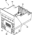
Figure 11 is the perspective view that can removably install on it according to the embodiment of the head unit of the ink tank of first embodiment.
Figure 12 A and 12B demonstrate ink tank are installed to fitting operation (a)-(d) on the head unit.
Figure 13 be according to another embodiment be used for receive ink with the perspective view (a) of the head unit that writes down operation and the perspective view of the balladeur train of coupling with it from ink tank, and n represents the perspective view (b) of head unit and balladeur train state connected to one another.
Figure 14 is the perspective view of outward appearance that can use the ink-jet printer of ink tank.
Figure 15 is the perspective view that saves the master component lid of recording equipment shown in Figure 14.
Figure 16 shows to be arranged on according to the schematic side elevation of the photoconduction on the ink tank of second embodiment of the invention to the function of part.
Figure 17 is the schematic side elevation that improves embodiment of Figure 16.
Figure 18 is side view (a), front view (b) and the upward view (c) of conduct according to the ink tank of the liquid container of another embodiment of second embodiment.
Figure 19 is schematic side elevation (a) and the enlarged drawing (b) of photoconduction to the major part of part, to demonstrate the function of photoconduction to part.
Figure 20 is according to the side view (a) of the improvement embodiment of structure shown in Figure 180 and front view (b).
Figure 21 is side view (a), vertical view (b), upward view (c) and the front view (d) of conduct according to the ink tank of the liquid container of third embodiment of the invention.
Figure 22 is the schematic plan (a) of carrying the tape deck of a plurality of ink tanks 1 shown in Figure 21 on it, and when being illustrated in balladeur train and moving facing to the explanatory view (b) of the ink tank of the light receiving part of the lower position that is located at printer.
Figure 23 is the schematic side elevation of the photoconduction of ink tank shown in explanation Figure 22 to the function of part.
Figure 24 is side view (a), vertical view (b), upward view (c) and a front view (d) that improves the ink tank of embodiment as embodiment shown in Figure 21.
Figure 25 is the schematic elevational view (a) of carrying the tape deck of a plurality of ink tanks 1 shown in Figure 24, and demonstrates when balladeur train moves the explanatory view (b) facing to the ink tank of the light receiving part of the lower position that is located at printer.
Figure 26 be the explanation light beam from incide the photoconduction shown in Figure 24 (a) on part to penetrating the schematic side elevation of action of this photoconduction to part.
Figure 27 is a schematic side elevation that improves embodiment of ink tank shown in Figure 24 (a).
Figure 28 is the perspective view of conduct according to the ink tank of the liquid container of one embodiment of the invention.
Figure 29 is side view (a), vertical view (b), upward view (c) and the front view (d) of ink tank shown in Figure 28, and at the vertical view (e) and the front view (f) that omit ink tank under the situation of covering member.
Figure 30 is the block diagram of structure of the control system of expression ink-jet printer.
Figure 31 shows the structure of the signal line wiring of the signal transmission between the flexible cable that is used for ink tank and ink-jet printer aspect the substrate of ink tank.
Figure 32 is the circuit diagram that expression is provided with the detailed structure of substrates such as controller.
Figure 33 is a circuit diagram that improves embodiment of substrate shown in Figure 32.
Figure 34 is that the based memory array of explanation writes data and therefrom reads the time-scale of the operation of data.
Figure 35 is the time-scale that explanation LED101 activates and goes to activate.
Figure 36 is the flow chart of the explanation control program relevant with the installation and removal of according to an embodiment of the invention ink tank.
Figure 37 is the flow chart of the installation and removal process of ink tank shown in Figure 36.
Figure 38 is a flow chart of at length representing the installation affirmation control among Figure 37.
Figure 39 shows state (a), and wherein in the control procedure that is used for mounting and dismounting ink tank, all ink tanks all correctly are installed on the correct position, thereby LED is switched on respectively; After figure (b) showed and closes the lid of master component after luminous along with LED, balladeur train moved to and utilizes light to confirm the motion of the position of (light affirmation).
Figure 40 shows bright dipping affirmation program (a)-(d).
Figure 41 also shows bright dipping affirmation program (a)-(d).
Figure 42 is the flow chart of explanation according to the logging program of the embodiment of the invention.
Figure 43 is the schematic side elevation (a) and the schematic elevational view (b) of ink tank according to still another embodiment of the invention.
Figure 44 is a schematic side elevation that improves embodiment of structure shown in Figure 43.
Figure 45 is a schematic side elevation that improves embodiment of structure shown in Figure 43.
Figure 46 is the circuit diagram according to the substrate with controller etc. of yet another embodiment of the invention.
Figure 47 is the time-scale of the operation in the structure of this embodiment.
The specific embodiment
Below in conjunction with accompanying drawing the preferred embodiments of the present invention are described.
1. first embodiment.
1.1 the description of first embodiment.
Fig. 1 is according to the side view of the ink tank of first embodiment of the invention (a), front view (b) and upward view (c).In the following description, the front side of ink tank is that this side direction user provides information (luminous by the display part that will be described to from behind) towards that side of the user who handles this ink tank (the installation and removal operation of ink tank).
In Fig. 1, the ink tank 1 of this embodiment has the supporting member 3 that is supported in its front side on the bottom.Integrally molded by the supporting member 3 that resin material is made with the shell of ink tank 1, and when being installed to ink tank 1 on the pan straddle, ink tank 1 can move around the part that will be supported of this ink tank.Ink tank 1 is respectively equipped with first bonding part 5 and second bonding part 6 on its rear side and front side, they can engage with the lock part on being arranged on pan straddle.In this embodiment, first bonding part 5 and second bonding part 6 are one with supporting member 3.By engaging of first bonding part 5 and second bonding part 6 and lock part, ink tank 1 is installed in the pan straddle reliably.Below with reference to the operation in Figure 12 (a)-(c) description installation process.
The bottom surface of ink tank 1 is provided with the ink supply port 7 that is used to supply ink, by ink tank 1 is installed on the pan straddle, can makes the ink of the record head that this ink supply port and back can be described to introduce opening and be connected.The position of intersecting in bottom side and front side, basal component are arranged on the bottom side of supporting part of supporting member 3.This base component can be laminar or tabular.In the description afterwards, will be called " substrate " 100.
The 26S Proteasome Structure and Function of the major part of this embodiment is described below with reference to Fig. 2 and Fig. 4.Fig. 2 is the schematic side elevation (a) and the enlarged drawing (b) of its major part, shown be located at according to the photoconduction on the ink tank of first embodiment of the invention to the part etc. function.Fig. 4 is mounted in side view (a) and the front view (b) of an embodiment of the controller substrate on the ink tank of first embodiment.
Shown in Fig. 2 (a), first bonding part 5 by ink tank 1 and second bonding part 6 respectively with first lock part 155 of support 150 and engaging of second lock part 156, ink tank 1 is installed into reliably or is installed to and have record head 105 ' head unit 105 support 150 in aggregates on.At this moment, the contact (connector head) 152 that is arranged in the support 150 electrically contacts to set up electrical connection with the lip-deep contact that is electrode pad 102 (Fig. 4 (b)) form towards the outside that is arranged on substrate 100.
The inside of ink tank 1 is divided into ink storing chamber 11 and the negative pressure generation member accommodating chamber that contiguous front side is provided with, and this negative pressure produces ground setting of the contiguous rear side of member accommodating chamber and forms fluid with ink supply port 7 and is communicated with.Ink storing chamber 11 and negative pressure produce the member accommodating chamber and form the fluid connection each other by connected entrance.In this embodiment, ink is only contained in ink storing chamber 11, and negative pressure generation member accommodating chamber holds the blotting material of being made by sponge, the collection of filaments etc. (negative pressure for porous member produces member in this embodiment) that is used for keeping by infiltration ink.Porous member is used for producing enough negative pressure so that the curved hydraulic resistance balance that forms with nozzle at record head, thereby prevents that ink from partly leaking into the outside from ink-jet, and allows to carry out ink-jet by activating record head.
The internal structure of ink tank 1 is not limited to this separation structure that inside is divided into the porous member accommodating chamber and contains the locker room of ink separately.In another embodiment, porous member can occupy the most inner space of ink tank.The negative pressure production part is not limited to use this of porous member a kind of.In another embodiment, ink is contained in separately by in the air bubble-shaped member of making such as the elastomeric material of rubber etc., and this member produces tension force along the direction that makes its volumetric expansion.In this case, produce negative pressure to keep ink by the tension force in the air bubble-shaped member.In another embodiment, at least a portion ink spatial accommodation is made of flexure member, and ink is contained in separately in this space, wherein applies elastic force to flexure member, produces negative pressure thus.
As Fig. 4 (a) with (b), be provided with towards the surface of the substrate 100 of ink tank 1 be used to send visible light such as the such luminous component 101 of LED and be used to control the control member 103 of luminous component.Control member 103 control luminous components 101 are luminous in response to the signal of telecommunication that provides by pad 102 from connector 152.
Shown in Fig. 2 (a) and 2 (b), photoconduction extends upward from the front side wall facing to the shell of the position of luminous component 101 and ink tank to part 121 with keeping certain interval, and is used to guide light.Its free end portion constitutes and is easy to the display part 122 observed by the user.Irradiant part is called as " display part " or " emission parts ".In order to suppress light quantity in the decay to the stroke of part 121 from luminous component 101 to photoconduction, luminous component 101 is arranged in the substrate 100 so that near photoconduction to the position of the light incidence surface 123 of part 121 towards this surface 123 (Fig. 2 (b)).
Like this, luminous component and display part are separated from each other, thereby the display part is arranged on the front side place of ink tank, that is, have the top of this side of securing rod, be convenient to the user thus and observe.Will be described to as following, and when in the master component that light receiving part is arranged on printer, can guarantee to receive light from the display part by light receiving part.Be arranged on ink tank 101 owing to be used for the photoconduction that luminous component is connected with light between the display part to part 121, so needn't be provided for the lead of supply of electric power and signal exchange etc., so, can luminous component 101 and display part 122 be arranged on separately optimum position with low cost.Thereby, for configuration display part 122 provides the free degree to satisfy the convenient purpose of using of user, thereby make the user can easily observe the emission of light, can thus be the user predetermined information relevant with ink tank 1 is provided.By utilizing photoconduction Unitarily molded to the shell of part 121 and ink tank 1, manufacturing cost can significantly not increase to part 121 owing to being provided with photoconduction.
In this embodiment, between the front side wall of the shell of the ink tank of part 121 and formation ink storing chamber 11, there is air layer (space) at photoconduction.Can consider to make photoconduction in aggregates fully with the front side wall of ink tank shell to part, in other words, with the front side wall of ink tank shell as photoconduction to part.But, the favourable part of the structure of this embodiment is, light can be conducted to display part 122.To be described this point below.
In this embodiment, as Fig. 2 (a) with (b), integrally link to each other to the shell of part 121 by photoconduction, but be independent of front side wall with ink storing chamber 11.That is, utilize the structure of this embodiment, between part 121 and ink storing chamber 11, air layer is set at photoconduction.The shell of ink tank is made by polypropylene material.If photoconduction to part 121 fully and ink storing chamber 11 outer shell integrated, then photoconduction must be a polypropylene to the material of part 121.
Shown in Fig. 2 (b), in this embodiment, the light that luminous component 101 sends be incident on be photoconduction on the light incident surface 123 of the end face of part 121, described light passes photoconduction and arrives display parts 122 to be shown to the user to part 121.As described below, luminous component 101 sends visible light and makes light scattering.Therefore, just like the multi beam light shown in the arrow A 1-A3.
Here, suppose polypropylene be 1.49 in the refractive index of photoconduction in part 121 (=n1).Since the refractive index of air be 1.00 (=n2), so the critical refraction angle of light from the polypropylene to the air determined by following Snell laws of refraction:
n1?sinθ1=n2?sinθ2
That is, the critical refraction angle approximately is 43 °.
Therefore, the light that point (i) in Fig. 2 (b) is sentenced 43 ° or bigger incidence angle θ incident is reflected fully by the interface between polypropylene (photoconduction is to part 121) and air, and light marches to display part 122 at photoconduction in part 121 when repeating by the total reflection shown in arrow A 1 or the A3.When incidence angle θ was not more than 43 °, light transmission can not arrive display part 122 to air.
The predetermined information of aforementioned ink tank (liquid container) 1 comprises: correctly whether the installment state of relevant ink tank 1 information of (whether thoroughly installing); The information of the correctness of the installation site of relevant ink tank (ink tank whether be installed in according to the color of contained ink wherein and on the tram of definite support); With or the information of relevant ink remaining amount (whether ink remaining amount enough).Can by whether luminous, luminous state (flicker etc.) wait and show these kinds of information.
The manufacture method of ink tank will be described below.The inside of ink tank 1 is divided into ink storing chamber 11 and negative pressure generation member accommodating chamber, and ink storing chamber 11 contiguous front sides are provided with, and negative pressure produces the contiguous rear side setting of member accommodating chamber, and is communicated with ink supply port 7 formation fluids.Ink storing chamber 11 produces member accommodating chamber formation fluid by connected entrance and negative pressure and is communicated with.The upper surface that negative pressure produces the member accommodating chamber is provided with exhaust outlet 12A.Be provided with by preparation have the contact, the main body of the ink tank 1 of the substrate 100 of controller and luminous component, then to its inner ink that injects, can produce the ink tank 1 of Fig. 2.For example can on the upper surface of ink storing chamber, be formed for the ink inlet of this purpose.After injecting ink by the ink inlet, inlet is sealed by containment member 11A.
Selectively, after the ink I in ink tank uses up, pull down containment member 11A or in the ink tank housing, form hand-hole, ink can be re-injected in the ink tank thus.As required, ink supply port 7 can transport ink tank 1 thus by sealings such as over cap or band (not shown).
1.2 improve embodiment (Fig. 3,5 and 8)
Foregoing structure all is embodiment, as long as luminous component 101 is used and can provide the predetermined information relevant with ink tank 1 to tape deck and user, just can do suitable improvement.To improve embodiment to some below is described.
Fig. 3 is a schematic side elevation that improves embodiment of explanation first embodiment.In this embodiment, photoconduction is one to part 121 with the front side wall that forms ink storing chamber 11.In this improved embodiment, the light quantity that arrives display part 122 was less than wherein being provided with light quantity in first embodiment in space at photoconduction between part 121 and ink storing chamber 11, if but the light quantity raising, this improvement embodiment is useful.This improvement embodiment is preferred, because make ink tank compact and improved ink and held rate.
Fig. 5 is the schematic side elevation of another improvement embodiment of explanation first embodiment.In this embodiment, photoconduction is formed by the member as the dividing member that separates with the shell of ink tank 1 to part 121, and they are combined into one.Utilize this embodiment, can select suitable material respectively.For example, photoconduction can be makrolon material or acrylic material etc. to the material of part 121, and the refractive index difference of the refractive index of these materials and air is very big, thereby can guide the light that penetrates from luminous component effectively.On the other hand, about the material of the shell of ink tank 1, can select that the evaporation of the ink I in the ink tank is had highly inhibiting polypropylene material.Because they can be made by different materials, so the material of the ink tank 1 that can in wideer scope, select to need not to be transparent.
Fig. 6 is the schematic side elevation of another improvement of explanation first embodiment embodiment.In this embodiment, be positioned at photoconduction and have to the display part 122 of the free end of part 121 and be hemispheric structure basically, and preferably by surface coarsening being made the light scattering.Utilize this embodiment, the light that is guided to part 121 by photoconduction is by the display part scattering, thereby the light quantity decay, but light can show from the display part with bigger angle.Like this, visual angle (scope) increases, and visuality is further improved.
Fig. 7 is the schematic side elevation ((a) and (b)) of the another improvement embodiment of explanation first embodiment.In this embodiment, photoconduction is made by an integrated member 131 to part 121, supporting member 3 and the part that adheres to substrate 100 on it, and this integrated member 131 is members that the member with the shell that constitutes ink tank 1 separates.Thus, similar to embodiment shown in Figure 5, can select suitable material to satisfy the member that constitutes the ink tank shell respectively and to constitute the requirement of photoconduction to the member of part.Shown in Fig. 7 (b), it is separable making substrate 100 members 131 adhered thereto, thereby after the ink I in ink tank 1 all used up, member 131 can be installed on the new ink tank, that is, it can be reused.This has reduced operating cost because substrate 100 and/or luminous component 101 these can reuse than expensive component relatively.
Fig. 8 is the schematic side elevation of describing the another improvement embodiment of first embodiment ((a) and (b)).In this embodiment, photoconduction is to part 121 and make substrate 100 part adhered thereto by integrated member 131 ' make, and separates on the shell of and this member 131 ' be connected to ink tank 1 and with the member that constitutes supporting member 3.Like this, similar to embodiment shown in Figure 5, make the selection of material more.In Fig. 8 (b), integrally have photoconduction to part 121 with make the member 131 of substrate 100 part adhered thereto ' be separable, thereby they can be reused.
In first embodiment and improve among the embodiment, between part 121, be provided with air layer in ink storing chamber 11 and photoconduction, thereby the decay that has suppressed the incident light on the luminous component 101 is to improve visuality.This can realize by other member of planting between part 121 at ink storing chamber 11 and photoconduction.
Fig. 9 is the schematic side elevation of an improvement embodiment again of explanation first embodiment.In this embodiment, at photoconduction to part 121 and hold between the front side wall surface of ink storing chamber 11 of ink I the plant refractive index less than the low-refraction member 108 of photoconduction to the refractive index of part 121.The photoconduction of this embodiment is the members that separate with ink tank 1 to part 121, and is made by the Merlon with high light transmittance.Low-refraction member 108 is made by polytetrafluoroethylmaterial material.
Here, the refractive index of Merlon is 1.59, and the refractive index of polytetrafluoroethylene (PTFE) is 1.35.According to Snell laws of refraction, the critical refraction angle of light from the Merlon to the polytetrafluoroethylene (PTFE) approximately is 58 °, and therefore, the light that sends from luminous component 101, the light of incidence angle in 58 ° to 90 ° scopes can arrive display part 122.
In this embodiment, low-refraction member 108 can be replaced with the reflecting member that is made of metal.In the different previous embodiment of refractive index between the employed therein material, the light that does not satisfy total reflection condition is by transmission, and the result causes the light summation decay more or less.By reflecting member is set, incide on the incidence surface 123 and the light that arrives reflecting member can all be reflected basically.Like this, light conducting expeditiously, and improved visuality.
Figure 10 is the schematic side elevation of an improvement embodiment again of explanation first embodiment.In this embodiment, to part 121 and hold and do not have between the front side wall of ink storing chamber 11 of ink I to be provided with as the member of (Fig. 9) such as low-refraction members 108, opposite photoconduction contacts with each other to the front side wall of part 121 and ink storing chamber 11 at photoconduction.But, in this embodiment, ink storing chamber 11 is by making with low-refraction member 108 similar polytetrafluoroethylmaterial materials, and photoconduction is made by Merlon to part 121.For this reason, similar to embodiment shown in Figure 9, can be will be transmitted to display part 122 from the light that luminous component 101 sends.
Improve among the embodiment at these, luminous component is what to separate with the display part, and will be used for forming betwixt the photoconduction that light connects and be arranged on ink tank 101 to part 121, thereby luminous component 142 and display part 122 can be arranged at low cost on the optimum position separately, and do not need to be provided for the lead of supply of electric power and signal exchange, and these leads may make operability and observe variation.Thereby, so just for arranging display part 122 so that user's operation provides the design space, luminous thereby the user can easily observe, can provide the predetermined information relevant for the user thus with ink tank 1.
The improvement embodiment of first embodiment is not limited to above-mentioned those.Those of ordinary skill in the art can be further improved these embodiment in spirit of the present invention.For example, in the aforementioned embodiment, photoconduction is made by resin material to part, and utilize this material and the air that is in contact with it between the difference of refractive index guide light.But, can use the optical fiber that comprises core and covering.Can use hollow member (stainless steel tube) to replace solid photoconduction to part with interior reflective surface.
Two or more previous embodiment can be made up.Surface treatment in conjunction with the described display part 122 of Fig. 6 can be used among first embodiment or its improvement embodiment.
Second embodiment that will describe below this is applicable to, the 3rd embodiment and improvement embodiment thereof.
1.3 the mounting portion of ink tank (Figure 11-Figure 13):
Figure 11 is the perspective view of an embodiment that expression has the head unit of support, and the ink tank according to first embodiment can be installed on this support.
Fig. 7 is explanation according to the schematic side elevation of the operation of the installation of the ink tank of first embodiment and dismounting (a)-(c).Mounting portion described here can be applicable to embodiment described below and improves embodiment.
An embodiment of spendable record head 105 comprises the fluid passage that constitutes nozzle, is arranged on the electrothermal transducer element in the fluid passage.Provide electric pulse according to tracer signal to the electric transducer member, the ink in fluid passage applies heat energy thus.This changes the state of ink and produces bubble (boiling), so pressure sharply increases, thus with the ink jetting nozzle.The part 157 that electrically contacts that electrically contacts part (not shown) and head unit 105 that is used for the signal transmission that is arranged on the balladeur train 203 that below can be described to is electrical contact with each other, thereby can pass to tracer signal by conductor part 158 the electric transducer member drives circuit of record head 105.Conductor part 159 extends to connector 152 from electrically contacting part 157.
When being installed to ink tank 1 on the head unit 105, make support 150 be higher than support 150 (Figure 12 (a)), and first bonding part 5 that is the projection form that is arranged on the ink tank rear side is inserted be arranged in the support rear side in first lock part 155 of through-hole form, thereby ink tank 1 is placed on the inner bottom surface of support (Figure 12 (b)).By keeping this state, shown in arrow P, the upper end, front side of ink tank 1 is depressed, ink tank 1 is rotating around the bonding part between first bonding part 5 and first lock part 155 on the direction shown in the arrow R thus, thereby the front side of ink tank is moved down.In the process of this action, supporting member 3 moves along the direction shown in the arrow Q, and second lock part 156 (upper end-face edge of support front side) (Figure 12 (c)) that is arranged on the support front side is pressed in the side that will be arranged on second bonding part 6 in the supporting member 3 simultaneously on the ink tank front side.At this moment, the connector 152 of master component side begins to contact the pad 102 that is arranged in the ink tank.If the user stops fitting operation (that is, the user no longer depresses container (on the P direction)) in this stage, supporting member 3 is just crooked at this moment, and therefore, supporting member 3 elastic force own lift ink tank.Like this, prevented to electrically contact, and reminded user's ink tank not install fully.Thereby, can prevent under the situation of the ink tank of not installing fully, to print operation.
When the upper surface of second bonding part 6 arrives second lock part 156 that is arranged on below the upper end side marginal portion through the upper end side marginal portion of support front side below, supporting member 3 moves at supporting member 3 elastic force effect lower edge direction Q ' own, thereby makes second bonding part 6 by 156 lockings of second lock part.The structure of second lock part 156 be not limited to above-mentioned those.Form the space by upper end side edge part office, can constitute the lock part, and can constitute the lock part as the step part among this embodiment by being provided with in the support front side.(Figure 12 (c)) in this state, second lock part 156 flexibly promotes ink tank 1 in the horizontal direction by supporting member 3, thereby makes the rear side of ink tank 1 abut against the rear side of support 150.Contacting between the absorbing material in the ink supply port 7 in the ink guide opening 107 by support and the ink tank 1, ink tank 1 is subjected to along the power of direction z (shown in Figure 12 (d)).Under the effect of first lock part 155 that engages with first bonding part 5 and second lock part 156 that engages with second bonding part 6, moving up of ink tank 1 is suppressed.At this moment, finish the additional installation of ink tank 1, ink supply port 7 is connected with ink guide opening 107, and pad 102 is electrically connected with connector 152.
Such scheme has used " lever " principle in the installation process shown in Figure 12 (c), wherein the bonding part between first bonding part 5 and first lock part 155 is a fulcrum, and the front side of ink tank 1 is the power point that applies power.Coupling part between ink supply port 7 and the ink guide opening 107 is the operating point between power point and fulcrum, and this operating point is preferably near fulcrum.Therefore, ink supply port 7 is pressed on the ink guide opening 107 with big power owing to the rotation of ink tank 1.At the elastic component with higher elasticity of the setting of connecting portion office such as filter, absorbing material, filler etc.,, thereby prevent that ink from leaking from this connecting portion office so that guarantee the ink connectivity.
Thereby this structure, setting and fitting operation are preferred, because this member is because bigger power strain.When finishing fitting operation, first lock part 155 that engages with first bonding part 5 and second lock part 156 that engages with second bonding part 6 are used to prevent that ink tank 1 from rising leaves support, therefore, suppressed the recovery of elastic component, thereby made this member keep suitable strain.
On the one hand, pad 102 and connector 152 (electric contact) are made by the conductive material bigger than rigidity such as metal, to guarantee to satisfy its electrical connection properties.On the other hand, from preventing to damage and have the angle of enough durability, the excessive contact force between them is worthless.In this embodiment, they are arranged on as far as possible on fulcrum position far away, more particularly, in this embodiment, are arranged near the front side of ink tank, make the contact force minimum thus.
In this embodiment of this embodiment, substrate 100 was arranged on the bottom side that makes ink tank 1 and the inclined surface that the front side of ink tank 1 is connected, that is, and and therebetween corner part office.When consider be about to finish installation before, when only making under pad 102 and connector 152 state of contact equilibrium of forces, make to impose on the component that reaction force pad 102 and that apply the installing force balance in vertical direction downwards (power that vertically makes progress) is included in the actual contact pressure between pad 102 and the connector 152 by connector 152 in the contact site office.Therefore, when the user when ink tank is pushed downwards in the installation position, the extra ink tank installing force that is used for the electrical connection between substrate and the connector is less, thereby operability may be very little.
When ink tank 1 is pushed downwards in the installation position that first bonding part 5 and first lock part 155 are engaged with each other, second bonding part 6 and second lock part 156 are engaged with each other, and are produced the component (power that pad 102 is slided on connector 152) on the surface that is parallel to substrate 100 by this motive force.Therefore, good electrical connection properties and finishing of having guaranteed that ink tank installs are provided.In addition, electrical connections is positioned at a position that is higher than the ink tank bottom side, so the possibility that the ink of leakage gets there is less.In this embodiment; ink guide opening 107 is arranged in the bottom surface of the ink tank that is close to first bonding part 5; and pad 102 is arranged on the corner part office away from the front side of first bonding part, thereby can protect the user to avoid influence at the ink at ink guide opening 107 places in the installation and removal operating process of ink tank.
Like this, from the size of required ink tank installing force, guarantee the viewpoint of the pollution of the ink that electric contact state and protection user avoid leaking, the structure of above-mentioned electrical connections and arrange it is favourable.
As previously mentioned, utilize simple structure can guarantee ink tank is installed on the tram in the tape deck, and guaranteed stable electrical connection, and can not influence the operability in the ink tank installation process by contact pad being set in above-mentioned position.In addition, by the top place of (that side with securing rod) is provided with from luminous component to luminous display part, outside in the ink tank front side, improved demonstration to the user.Therefore, structure of the present invention can be used for providing various improvement.
Be used for the structure of mounting portion that first embodiment or its improve the ink tank of embodiment and be not limited to the sort of shown in Figure 11.
With reference to Figure 13 this point is described below.Figure 13 be according to another embodiment be used for receive ink with the perspective view (a) of the head unit that writes down operation with can be used for the perspective view of the balladeur train of this head unit from ink tank, and the perspective view (b) of representing head unit and balladeur train state connected to one another.
Shown in Figure 13 (a), the head unit 405 of this embodiment is that with the difference of foregoing those (supports 150) it does not have and the corresponding holder part in ink tank front side, second lock part or connector.To aforementioned that is similar, its bottom side is provided with the ink guide opening 107 that will link to each other with ink supply port 7 to head unit 405 in others.Its rear side is provided with first lock part 155, and the back side be provided be used for signal transmission electrically contact the part (not shown).
On the other hand, shown in Figure 13 (b), balladeur train 415 can move along axle 417, and is provided with the lever 419 that is used for fixing head unit 405, and with record head electrically contact that part is connected electrically contact part 418.Balladeur train 415 also is provided with and the corresponding holder part of the structure of ink tank front side.Second lock part 156, connector 152 and the conductor part 159 that is connected on the connector are arranged on the balladeur train side.
Utilize this structure, when being installed to head unit 405 on the balladeur train 415, (shown in (b), constitute the mounting portion of ink tank as Figure 13.Like this, by with similar fitting operation embodiment illustrated in fig. 15, formed being connected and being connected between pad 102 and connector 152 between ink supply port 7 and ink guide opening 107, and finished fitting operation.
1.4 recording equipment (Figure 14-Figure 15):
Figure 14 shows the outward appearance of the ink-jet printer 200 that can use aforementioned ink tank.Figure 15 is a perspective view of opening the printer of master component lid 201 shown in Figure 14.The tape deck that can use these embodiment and improve embodiment is described below.
As shown in figure 14, the printer 200 of this embodiment comprises: master component; Be positioned at row's paper disc 203 of master component leading flank; Be positioned at the automatic paper feeding device (ASF) 202 of its rear side; Master component lid 201; Cover other housing parts of critical piece, described critical piece comprises and moves the mechanism that the balladeur train that carrying record head and ink tank writes down with the moving process at balladeur train with being used for scanning.Also be provided with the guidance panel part 213 that comprises display unit, main switch and recovery switch, the state that irrespectively shows printer is opened or closed to described display unit and master component lid.
As shown in figure 15, when master component lid 201 is opened, the user can see movably scope, it is carrying the neighbouring part of head unit 105 and ink tank 1K, 1Y, 1M and 1C (for for simplicity, below can only represent ink tank with Reference numeral 1).In this embodiment, when opening master component and cover 201, carry out along continuous operation, (" container replacing position ", as shown in FIG.), the user can carry out ink tank here and change operation etc. thereby balladeur train 205 automatically arrives the centre position.
In this embodiment, corresponding to corresponding ink, the record head (not shown) is the substrate that is installed in the head unit 105.By moving of balladeur train 205, record head sweep record material, during this period, record head sprays ink to print.Balladeur train 205 can engage with the axis of guide 207 that extends on the moving direction of balladeur train 205 slidably, and can move as described above under the effect of carriage motor and movement transferring thereof.The jet data of exporting by flexible cable 206 according to the control circuit from be arranged on the master component side corresponding to the record head of K, Y, M and C (black, yellow, magenta and cyan) ink sprays ink.Set paper-feeding mechanism comprises paper feed roller, exit roller etc., so that carry the recording materials (not shown) from automatic paper feed 202 to row's paper disc 203.Head unit 105 with whole ink container holder is removably mounted on the balladeur train 205, and each ink tank 1 is detachably mounted on the head unit 105.
During record or printing, record head is by above-mentioned motion sweep record material, and during this period, record head is to spraying ink on the recording materials so that carry out record on the corresponding width of the scopes with ejiction opening array record head recording materials.In scan operation and in the time period between the scan operation next time, paper-feeding mechanism is by carrying recording materials with the corresponding preset distance of this width.Write down like this, in order to cover the whole zone of recording materials.In the end of record head mobile scope, be provided with the injection updating block of the lid that comprises the side that is used to cover record head with ejiction opening owing to the motion of balladeur train.Therefore, record head moves to the position of updating block at interval with preset time, and experiences the renewal process that comprises preparation injection and so on.
More particularly, after the position of groove is changed, the luminous component 101 of the ink tank 1 that comprises small volume of ink is switched on or glimmers, the user can see this situation to part 121 and display part 122 by photoconduction.This is applicable to each ink tank 1.In another embodiment of the switching controls of luminous component, when being installed to ink tank 1 on the tram, the luminous component 101 of container is shinny, and the user can observe this situation by photoconduction to part 121 and display part 122 thus.Similar to control to the ink-jet of record head, by supplying with control data (control signal) via flexible cable 206 to each ink tank, carry out these control from master component side control circuit.
2. second embodiment (Figure 16-Figure 20).
In the aforementioned embodiment, photoconduction to part 121 from extending upwardly to the display part 122 that is arranged on top end near the luminous component 101.To the embodiment that the display part is arranged on the user's that is more convenient for position be described.The Reference numeral identical with previous embodiment represents to have the member of corresponding function, and for for simplicity, omitted the detailed description to these members.
Figure 16 is that explanation is located at according to the schematic side elevation of the photoconduction on the ink tank of second embodiment of the invention to the function of part.In this embodiment, light is directed to display part 322 from luminous component 101, and be used for photoconduction that the user observes to part 321 with at photoconduction to part 321 and be used to hold between the front side wall surface of ink storing chamber 11 of ink I and do not have the mode in space to extend upward, and make the free end portion bending, thereby display part 322 is orientated along the upper right side.The same with previous embodiments, in this embodiment, the display part is set at the top of the front side (side that promptly has securing rod) of ink tank, thereby can be so that user's observation.
Under the situation of this structure, similar to first embodiment, light can be reached display part 322, suppresses simultaneously from the decay of whole light of luminous component 101 incidents.And, make photoconduction to part 321 bendings, so that display part 322 is orientated towards the upper right side among the figure, make the user can easily observe this display part 322.
Figure 17 is a schematic side elevation that improves embodiment of structure shown in Figure 16.Equally, in this embodiment, photoconduction is crooked to part 321, but low among aspect ratio Figure 16, makes the back side of end face 310 facing to supporting member 3 (more specifically saying so as the operation part 3M of the part that will be handled by the user).The operation part 3M of supporting member 3 at least in this embodiment is made of the transmissive member among this embodiment.
As shown in figure 17, in this embodiment, the light that sends from luminous component 101 guides to end face 310 by photoconduction to part 321, then light is guided into operation part 3M.Like this, the operation part 3M of the supporting member 3 that is made of transmissive member is lighted.In other words, operation part 3M itself is as the display part that information is provided to the user.
This embodiment provides the advantageous effects identical with first embodiment.In addition,, will be lighted, therefore, when the user is alerted the replacing ink tank, can directly be recognized the target ink tank, can also directly be recognized the part that the installation or removal ink tank will be handled by the operation part 3M that the user handles according to these exemplary embodiments.More eye-catching for the light that makes operation part 3M place, can be provided for the part of an amount of light of scattering for operation part 3M.
For being set, the display part make the structure of optical axis bending be not limited to make photoconduction crooked to part.To be described this point.
Figure 18 is side view (a), front view (b) and the upward view (c) of conduct according to the ink tank of the liquid container of another embodiment of second embodiment.Photoconduction to the upwardly extending from here position of part 450 basically with previous embodiment in identical, but the photoconduction among this embodiment is not crooked to part 450, but extends as the crow flies basically.The top ends office is provided with an inclined surface 451.The position of this inclined surface 451 is positioned at the back side of the operation part 3M of supporting member 3, and the part relative with the back side of operation part is higher, and the part relative with the front side of ink storing chamber 11 is lower.Between the surface of the front side wall of part 450 and ink tank 1, there is the space at photoconduction.When making photoconduction when the part 450 and the shell of ink tank 1 are Unitarily molded, whole member is made by light transmissive material.
Structure and the function of the photoconduction of this embodiment to part 450 is described below.Figure 19 is schematic side elevation (a) and the enlarged drawing (b) of photoconduction to the major part of part, shows the function of photoconduction to part.
As shown in these figures, each photoconduction extends upward in this position relative with luminous component 101 from the bottom side end face to part 450.Therefore, when luminous component 101 was luminous, light was guided to the inclined surface 451 that is positioned at the top ends office from the end face of photoconduction to part 450 bottom sides, and by inclined surface 451 reflections, arrived operation part 3M.Similar to embodiment shown in Figure 17, the structure of this embodiment makes the light that sends from the luminous component 101 that is arranged on ink tank 1 bottom side be directed to operation part 3M by photoconduction to part 450, therefore, the user of manipulation operations part 3M recognizes the predetermined information relevant with ink tank 1 naturally.
As follows in the optimum position relation of photoconduction between part 450, inclined surface 451 and luminous component 101.From angle that a large amount of light is provided preferably, in order to make the light that is sent by luminous component 101 guide to inclined surface 451 by photoconduction to part 450, luminous component 101 and photoconduction are relative and be positioned at photoconduction (vertical to the optical axis 456 of part 450 with photoconduction) on the outstanding plane of the cross section of part 450 to the end face of part 450 bottom sides.
For making the light by inclined surface 451 reflections successfully arrive operation part 3M, preferably, the inclination angle with respect to optical axis 456 of inclined surface 451 is not less than critical angle, so that whole reverberation.For example, with the Unitarily molded photoconduction of ink tank 1 be that 1.49 polypropylene is made to part 450 by refractive index, determine total reflection condition (refractive index of air is 1) as follows according to Snell laws of refraction:
1.49sinθ=1
sinθ=1/1.49
θ is about 43 °.
Thereby, be not less than 43 ° with respect to the inclination angle (=incidence angle) of optical axis.In this embodiment, the inclination angle be 45 ° to satisfy the condition of total reflection.Like this, be tilted surface 451 reflection fully by photoconduction to the light of part 450 guiding, and be directed to operation part 3M, thereby improved visibility.
Figure 20 is a side view (a) and a front view (b) that improves the ink tank of embodiment according to structure shown in Figure 180.In this embodiment, photoconduction is the members that were arranged in 1 minute with ink tank to part 450.According to this embodiment, ink tank 1 and photoconduction can be made by suitable material respectively to part 450.At ink tank 1 is not under the situation about being made by light transmissive material, forms opening 32 on the part of operation part 3M.By this opening 32, user's eyes receive from the reverberation of photoconduction to the inclined surface 451 of part 450.
In Figure 18 and embodiment shown in Figure 20, inclined surface is provided with like this,, makes light with respect to equaling angle (angle of reflection) to operation part 3M reflection by photoconduction to the angle (incidence angle) of the optical axis of part 450 guiding that is.According to used conditions such as material, they correctly are provided with so that satisfy the condition of total reflection.
For reverberation effectively, inclined surface can be made by the material with high index of refraction or high reflectance, for example, can paste metal forming etc.
And, in other alternative, the operation part 3M of supporting member is not as the display part, but it is similar to embodiment shown in Figure 16, photoconduction extends to the position that is higher than operation part to part 450, and wherein the display part is formed to the top front of part 450 by the photoconduction of adjacent sloped surfaces part.
3. the 3rd embodiment (Figure 21-Figure 27)
According to the conditions such as position of printer, the user may watch the display part along different directions, therefore, wishes to send light from the display part in wideer scope.On the other hand, the display part not only is used for the user to be observed, but also is used for the ink tank detecting operation of the operation control of tape deck, and therefore, light receiving part 210 is arranged in the tape deck as shown in Figure 15 like that.
For example, when balladeur train 205 scanned with respect to light receiving part 210, ink tank and/or display part were passed through light receiving part 210 in succession.In the process of process, can check whether ink tank is installed in respectively on the correct position.More particularly, in the moment of certain ink tank in the face of light receiving part 210, the luminous component of the ink tank that contains color inks is activated lighting luminous component, thus luminous from the display part, suppose that this ink tank is arranged on the position in the face of light receiving part 210.If light receiving part 210 receives light, just judge this ink tank and be installed on the correct position, otherwise judge that ink tank is installed on the wrong position.For example, if latter event, write down operation with regard to stoping, and the luminous component by making the wrong ink tank of installing or the display part ink tank that glimmers and remind the user to open master component lid 201 and be reinstalled in place with the wrong location.Like this, eliminated owing to the mistake of or several ink tanks is installed and caused the incorrect problem of color reproduction, and the problem that ink tank of ink shortage is proposed caution and the ink tank that contains the q.s ink do not proposed mistakenly warn.
Be used for that this ink tank detects or the light receiving part 210 of control is fixed on equipment, make ink tank be carried on the balladeur train simultaneously and move back and forth, therefore, in detecting operation, fix with respect to the position relation of the display part of ink tank.For this reason, preferably, the location tolerance of the light receiving part of display part in tape deck allow among a small circle in luminous, thereby the density that will be directed to the light quantity of light receiving part maintains sufficiently high level, this is opposite with the viewpoint that the user observes.
Thereby, require the display part to satisfy the function of contradiction.The embodiment that will be intended to satisfy the requirement of these contradictions below is described.
Figure 21 is side view (a), vertical view (b), upward view (c) and the front view (d) of conduct according to the ink tank of the liquid container of third embodiment of the invention.In these accompanying drawings, Reference numeral 550 expression photoconductions are to part (light guiding rib).Similar to previous embodiment, the end face of bottom side is holded up from the position in the face of luminous component 101.
Structure and the function of the photoconduction of this embodiment to member described below with reference to Figure 22 and Figure 23.
Figure 22 is the schematic plan (a) of carrying the tape deck of a plurality of ink tank 1 shown in Figure 21 on it, and when being illustrated in balladeur train and moving facing to the schematic diagram (b) of the ink tank of the light receiving part that is arranged on the printer lower position, wherein specifically illustrated cyan container 1C, magenta container 1M and yellow container 1Y.These ink tanks at ink tank transversely promptly, are set up in parallel on the moving direction (scanning direction) of balladeur train 205.In Figure 22 (b),, make a plurality of ink tanks towards the bottom (Figure 15) that is arranged on the light receiving part 210 in the printer by the motion of balladeur train.From the top (perpendicular to drawing) when seeing, photoconduction has T-shaped basically cross section to part 550, wherein T shape partly is included in scanning direction (left and right direction, x direction among the figure) goes up the part (part B) of extending, and along the part (part A) of giving prominence to from the mid portion of part B perpendicular to the direction (vertical direction, the y direction among the figure) of scanning direction.The photoconduction of this embodiment is the form of the bar with T shape cross section to part.
Figure 23 is the schematic side elevation of the photoconduction of ink tank shown in explanation Figure 22 to the function of part.The figure shows out such state, that is, the light that is sent by luminous component 101 is incident on photoconduction to conducting to arrive the head portion 552 of photoconduction to part on the part 550 and at photoconduction in part 550, and light directive outside wherein is shown in arrow 511.In this embodiment, luminous component 101 is arranged on such position, promptly, this surface of position at photoconduction to the part A of the T shape cross section at place, the end, bottom side of part 550 and the cross section between the part B, and will guide to part A and the part B of photoconduction by the light that luminous component 101 sends to part 550.
Here, the light receiving part 210 that is fixed in the tape deck can change according to the build-up tolerance of the installation of light receiving part 210 with respect to the relative position relation of ink tank.More particularly, with reference to Figure 22 (b), on balladeur train scanning direction (x direction), the vertical direction (y direction) vertical with this direction and vertical with the drawing of this figure direction (z direction) deviation can appear.According to this embodiment, photoconduction allows deviation to occur on these directions to the structure of part 550, also allows to be used to distinguish the correct ink tank detecting operation of the correctness of the correctness of installment state of ink tank and installation site.
Deviation on the z direction to from head portion 552 to light receiving part the last variation of 210 distance influential, and thereby influential to the detected light intensity that sends from head portion 552.But, can sets the appropriate threshold setting value and in the scope of tolerance, change, thereby in the ink tank detecting operation, the deviation of light receiving part 210 on the z direction do not become problem to allow light quantity.
By in the luminous component 101 scanning balladeur trains of the emission light of using ink tank 1, light receiving part 210 is received in the light that head portion 552 places penetrate continuously, and the deviation on the x direction is an acceptable.More particularly,, also transmitting and receiving of light can be in the scope that this deviation is taken into account, carried out, the ink tank detecting operation can be correctly carried out thus even light receiving part has deviation on the x direction.Part A is used to form the maximum (peak value) in the change curve of the light quantity that receives of light receiving part 210.Therefore,, can adjust the follow-up luminous moment of the luminous component 101 that is used for detecting operation, compensate the deviation on the x direction thus effectively according to some detection time of peak value.
In addition, if part A is not less than the position of related features scope of the installation of light receiving part 210 on the y direction in the length on the y direction, just can receive light from head portion 552.Like this, on degree as described below, can accept the deviation of light receiving part 210, that is, can correctly carry out the ink tank detecting operation along the y direction.Along with reducing of the length of part A, increase from the density of photoconduction, thereby the light quantity that is received by light receiving part 210 increases to the light of the end of part 550 outgoing.Like this, the influence of external interference is reduced to minimum, to guarantee the ink tank detecting operation.Thereby, can be according to the installation site tolerance of light receiving part 210 and the length of suitably selecting part A by the preferred light quantity that light receiving part 210 receives.
On the other hand, for example when ink tank is not enough, makes photoconduction be lighted or glimmer, and seen by the user to the head portion 552 (display part) of part.Therefore, wish that the outgoing zone is wide as to make the user see it with various angles from diverse location.By selecting size and structure, above-mentioned part A can allow light receiving part to carry out suitable detecting operation.On the other hand, by selecting size and structure, part B can provide enough wide light outgoing zone.Photoconduction to the head portion 552 of part 550 also along the horizontal expansion of ink tank 1, thereby luminous energy outgoing widely on width.Like this, increased effective area.
In this embodiment, photoconduction has T shape cross section to part.But, being not limited in this, photoconduction is can be therewith different to the structure of part, as long as selected structure and size make at the light of head portion 552 places outgoing enough.Head portion also can not be a T shape.
Figure 24 is the schematic plan of expression photoconduction to another embodiment of the structure of part.Figure 25 is the schematic elevational view (a) of carrying the tape deck of a plurality of ink tanks 1 shown in Figure 24, and when being illustrated in balladeur train and moving facing to the schematic diagram (b) of the ink tank of the light receiving part that is located at the printer lower position.Figure 26 be explanation from incide photoconduction shown in Figure 24 (a) on part to penetrating the schematic side elevation of state of this photoconduction to the light beam of part.
Similar to Figure 22, when the top is seen, photoconduction has T shape cross section basically to the structure of part 580, and wherein T shape partly is included in part (part B) of extending on the scanning direction and the part (part A) of giving prominence to from the middle body of part B on the direction vertical with the scanning direction.Photoconduction has the similar inclined surface 582 with embodiment shown in Figure 180 to part 580, and in Figure 25 (a), this photoconduction is blocked by inclined surface 582 to part 580.This is that the structure of T shape is made of part E that extends along scanning direction (x direction) when the front portion is seen and the part D that (vertical direction Figure 25 (a), z direction) extends from this part along the direction vertical with the scanning direction basically.
In Figure 26, the light that is sent by luminous component 101 incides photoconduction on part 580, conducts in part 580 at this photoconduction, penetrates by inclined surface 582 reflection and in the front portion (right-hand side among Figure 26) of the front side of ink tank.To foregoing similar, the inclination angle of inclined surface 582 set for be not less than critical angle, so that make by the light total reflection of photoconduction to part 580 guiding.For example, if photoconduction is made by polypropylene material to part 580, then this inclination angle approximately is 45 °.Scheme instead, for reverberation effectively, inclined surface can be made by the material with high index of refraction or high reflectance.For example, can on inclined surface 582, paste metal forming etc.
In this embodiment, light receiving part 210 is arranged to make emergent light in the front side of ink tank (y direction) rather than on top (z direction) locate to receive.In this case, to foregoing similar, light receiving part 210 deviation occurs on x, y and z direction.Equally, according to this embodiment, photoconduction allows deviation on these directions to the structure of part 550, also allows to be used to distinguish the correct ink tank detecting operation of the correctness of the correctness of installment state of ink tank and installation site.
Here, deviation on the y direction is corresponding to the deviation on the z direction in the previous embodiment, and it is influential to the variation of the distance the light receiving part 210 to outgoing position from light, but, by setting suitable threshold, this deviation is an acceptable, changes to allow light quantity, thereby finishes correct ink tank detecting operation.
Deviation on the x direction is the same with deviation on the x direction, and can receive the light of head portions 552 by light receiving part 210 in the mobile balladeur train in luminous luminous component 101 scanning ground of ink tank 1 continuously, and this deviation can be accepted.
In addition, the deviation on the z direction is corresponding to the deviation on the y direction in the aforementioned embodiment.If the length of the part D that measures in z direction when the front side is seen is not less than the installation site margin of tolerance of the light receiving part 210 on the z direction, just can receive light from head portion 582, thereby the installation of light receiving part 210 on the z direction is acceptable, and finishes correct ink tank detecting operation.
Similar to previous embodiment, the size of each several part D, E, structure etc. can be determined according to the operation of light receiving part and user's observation.
To the forward position (position of light outgoing) of part 580 display part is not set by photoconduction, the substitute is, back at the operation part 3M of supporting member 3 is provided with inclined surface 582, as shown in figure 27, thereby similar to embodiment shown in Figure 19, operation part 3M is as the display part.Similar to embodiment shown in Figure 20, operation part 3M can be provided with opening, can observe from the light of photoconduction to the inclined surface 582 of part 580 by this opening.
4. the 4th embodiment (Figure 28 and Figure 29):
Desired user can correctly be determined ink tank according to the luminous display part of ink tank.If the light quantity of outgoing is too low, then the user is not easy to detect light.On the other hand, if the light quantity of outgoing is too big, then be difficult to the liquid container of distinguishing adjacent.Light receiving part also has same problem.More particularly, light receiving part may receive the light near ink tank rather than target ink tank.
Below to being described by the correct embodiment that receives of user and light receiving part from the emergent light of display part.
Figure 28 is the conduct perspective view of the ink tank of liquid container according to an embodiment of the invention.Figure 29 is side view (a), vertical view (b), upward view (c) and the front view (d) of ink tank shown in Figure 28, and at the vertical view (e) and the front view (f) that omit ink tank under the situation of covering member.
The structure of this embodiment is with shown in Figure 24 substantially the same.Photoconduction has the cross section that is essentially T shape to part 580, and has an inclined surface 582, and extend upward from the position relative with luminous component 101, thereby light is from being arranged in the front side and providing the part (part corresponding with part D, the E of Figure 25) of display part 585 to penetrate.In this embodiment, relatively form predetermined opening 21A with display part 585, and cover the peripheral part of display part 585, so that limit the exit direction of light by emergent light limiting member 21.
A lid of Reference numeral 2 expression member, it is installed on the upper surface of ink tank 1 covering inside, and it has and is used for forming the pore 20 that fluid is communicated with between inside and surrounding environment.In this embodiment, emergent light limiting member 21 is for example made by thermoplastic elastomer, thereby it can be welded in and covers on the member 2 to form an internals.Because thermoplastic elastomer is transparent,, it reduces the emergent light on the round edge part so can being colored, thus the reception of light stable receiving unit 210 operation and raising user's observability.Perhaps, can use other material except that body, and it can be Unitarily molded with lid member 2 with same material.When lid member 2 is made by transparent material,, can limit emergent light by on the front surface of the part that constitutes emergent light limiting member 21 and in the rear surface at least one, rough structure being set or can carrying out blasting treatment to this surface.
According to this embodiment, suitably limited from the emergent light of display part, thereby for user's the observability and the operational stability of light receiving part, it is preferred can making light quantity.Photoconduction to part be not limited to aforesaid those, and its structure can be different from shown in Figure 24.The display part can be formed on the upper end face place of photoconduction to part.
5. control system:
5.1 general layout (Figure 30):
Figure 30 is the block diagram of an embodiment of structure of the control system of expression ink-jet printer.This control system mainly comprises the control circuit (PCB (printing wiring board)) in the printer master component, and by the ray structure of the LED of the ink tank of control circuit control.
In Figure 30, the data that control circuit 300 execution are relevant with operation control with printer are handled.More particularly, CPU301 carries out the processing that following meeting is described in conjunction with Figure 36-Figure 39 according to the program that is stored among the ROM303.RAM302 is used in the process that CPU301 handles as the workspace.
As Figure 30 schematically shown in, the head unit 105 that is carried on the balladeur train 205 has record head 105K, 105Y, 105M and 105C, and these record heads have a plurality of ejiction openings that spray black (K), yellow (Y), magenta (M) and cyan (C) ink that are respectively applied for.On the support of head unit 105, each ink tank 1K, 1Y, 1M and 1C removably are installed corresponding to each record head ground.
As previously mentioned, each ink tank 1 is provided with the substrate 100 that has LED101, is used for its display control circuit and pad (electric contact) etc.When correctly being installed in ink tank 1 on the head unit 105, the pad in the substrate 100 is contacted with the connector that is provided with corresponding to each ink tank 1 in the head unit 105.The connector (not shown) that is arranged in the balladeur train 205, the control circuit 300 that is arranged on the master component side are electrically connected, so that transmit signal by flexible cable 206.In addition, by head unit 105 is installed on balladeur train 205, the connector of balladeur train 205 and the connector of head unit 105 are electrical contact with each other so that carry out the signal transmission.In this structure, can between the control circuit 300 of master component side and each ink tank 1, transmit signal.Thereby control circuit 300 can be carried out the control that is used to switch on and off LED according to the order of describing below in conjunction with Figure 36-Figure 38.
Connector by flexible cable 206, balladeur train 205, be arranged on and between drive circuit etc., realize the connector of the head unit that signal connects and the control circuit 300 in the master component side in the record head, like the ink-jet approaches of record head 105K, 105Y, 105M and 105C, control.Thereby, the ink-jet of control circuit 300 each record head of control etc.
Be arranged on the light that near first light receiving part 210 one of the end of moving range of balladeur train 205 receives from the LED101 of ink tank 1, and will represent the signal supply control circuit 300 of this situation.As hereinafter described, 300 pairs of signals of control circuit respond to distinguish the position of ink tank 1 in balladeur train 205.In addition, along the motion path of balladeur train 205 encoder scale 209 is set, and balladeur train 205 correspondingly is provided with encoder detector 211.The detection signal of sensor is passed through flexible cable 206 supply control circuits 300, the shift position that obtains balladeur train 205 thus.This positional information is used for the injection control of each record head, also is used for wherein detecting the light affirmation process of ink tank position, below can be described this in conjunction with Figure 36.The second light emission/receiving unit 214 is arranged near the precalculated position in the moving range of balladeur train 205, and comprise light emission member and light-receiving member, and this part be used for to control circuit 300 outputs be carried on balladeur train 205 on the relevant signal of ink remaining amount of each ink tank 1.Control circuit 300 can detect ink remaining amount according to this signal.
5.2 the coupling part (Figure 31-Figure 35):
Figure 31 shows the structure that is used at the signal line wiring of the ink tank 1 of ink-jet printer and the transmission of the signal between the flexible cable 206 with regard to the substrate 100 of ink tank 1.
As shown in figure 31, in this embodiment, the signal line wiring that is used for ink tank 1 comprises four signal line, and (bus connection) all is shared to each in these holding wires for all four ink tanks 1.The signal line wiring of ink tank 1 comprises four signal line, that is: voltage source signal line VDD, its relevant with supply of electric power with such as the operation of the one group of building blocks of function that is used for carrying out luminous, as to activate ink tank LED101; Ground signalling line GND; Be used for providing and holding wire DATA such as relevant control signal (control data) of the such process of switching on and off of LED101 etc. from control circuit 300; And so and clock cable CLK of needs.In this embodiment, use four signal line, but the invention is not restricted to this situation.For example, can provide ground signalling, and under these circumstances, can in said structure, omit line GND by other structure.On the other hand, line CLK and line DATA can be made a shared line.
The substrate 100 of each ink tank 1 has the controller 103 that the signal by four signal line supplies is responded, and the LED101 that can move in response to the output of controller 103.
Figure 32 is the detailed circuit diagram that is provided with the substrate of such controller etc.As shown in FIG., controller 103 comprises I/O control circuit (I/O-CTRL) 103A, memory array 103B and led driver 103C.I/O control circuit 103A responds to the control data of carrying by flexible cable 206 from the control circuit 300 of master component side, with the display driver of control LED101, data writing and the reading of data in memory array 103B.In this embodiment, memory array 103B is the form of EEPROM, and can store the peculiar information of ink tank, for example relevant with ink remaining amount in ink tank information, the colouring information of ink are wherein also stored the manufacturing information of number such as ink tank, product batch number etc. in addition.Colouring information corresponding to the color that is stored in the ink in the ink tank is written in the presumptive address of memory array 103B.For example, colouring information is as the ink tank identifying informations of describing below in conjunction with Figure 34 and 35 (peculiar information), so that will work as writing data into memory array 103B or when therefrom reading or discern ink tank when controlling the actuating of LED101 at the particular ink container or going to activate.Write memory array 103B or the data of therefrom reading for example comprise the data of representing ink remaining amount.As previously mentioned, the ink tank of this embodiment is set in the bottom with prism, and when the surplus of ink diminishes, can detect this situation with optical means by prism.In addition, the control circuit 300 of this embodiment calculates the injecting times of each record head according to jet data.Ink remaining amount information is write among the memory array 103B of corresponding ink tank, and read this information.Like this, memory array 103B stores the information of ink remaining amount in real time.This information is also represented ink remaining amount with high accuracy, because this information provides by prism.And also the ink tank that can come identification to install with it is new or with installation more later.
Led driver 103C is used for applying supply voltage to LED101, so that it is luminous when the signal that provides from I/O control circuit 103A is in high level.Therefore, when the signal that provides from I/O control circuit 103A was in high level, LED101 was in on-state, and when signal was in low level, LED101 was in off-state.
Figure 33 is a circuit diagram that improves embodiment of substrate shown in Figure 32.This improvement embodiment and difference embodiment illustrated in fig. 21 are to apply to LED101 the structure of supply voltage, more specifically say, supply voltage is that vdd voltage source figure (pattern) from substrate 100 inside that are arranged on ink tank provides.Usually, controller 103 is embedded at semiconductor-based the end, and in this embodiment, only is the connecting terminal of LED at the suprabasil connecting terminal of semiconductor.The minimizing of connecting terminal number has influenced significantly by the occupied area in the semiconductor-based end, and in this sense, the attendant advantages of improving embodiment has been to reduce the cost at the semiconductor-based end.
Figure 34 is that the based memory array 103B of explanation writes data and therefrom reads the sequential chart of the operation of data.
Figure 35 be explanation LED101 actuating, remove the sequential chart that activates.
As shown in figure 34, when write memory array 103B, the beginning code, control routine, address code, data code that adds colouring information synchronously offers I/O control circuit 103A the controller 103 of ink tank 1 by the control circuit 300 of holding wire DATA (Figure 31) on the master component side according to described order and clock signal clk.Add the beginning that beginning code signal in the colouring information is represented data signal sequence at the beginning code, and color information signals is used to discern the particular ink container relevant with data signal sequence.Here, the color of ink not only comprises colors such as Y, M, C, also comprises these inks with variable concentrations.
As shown in FIG., colouring information has the corresponding code of shades of colour K, C, M and Y with ink.I/O control circuit 103A will be compared by the colouring information of coded representation and colouring information among the memory array 103B that is stored in ink tank itself.Have only when they are identical, just adopt follow-up data, otherwise just ignore follow-up data.Like this, even when data-signal when the master component side is supplied with all ink tanks jointly by the common signal line DATA shown in Figure 31, the also correct related ink tank of recognition data, because these data comprise colouring information, therefore, only can carry out processing, such as the writing of follow-up data, read, the actuating of LED, go to activate to the ink tank discerned (that is) only to correct ink tank based on follow-up data.As a result, (a kind of) data shared holding wire enough is used to write data, activates LED and removes to activate LED concerning whole four ink tanks, thereby has reduced the quantity of required holding wire.As can understanding at an easy rate, no matter how much quantity of ink tank is, (one) data shared holding wire is just enough.
As shown in Figure 34, the control model of this embodiment comprises " opening " and " pass " code that is used to activate and go to activate LED that below will describe, and is used for being listed as " reading " and " writing " code that writes and read at storage battle array device.In write operation, " writing " code is followed the colouring information code that is used to discern ink tank.Next code, that is, address code is represented the address that wherein will write data in the memory array, and last code, that is, and the content of the information that data code indicates to write.
The content of being represented by control routine is not limited to the foregoing description, and for example can increase and be used to confirm order and/or the control routine of reading order continuously.
For read operation, the structure of data-signal the same with in the write operation situation.The beginning code adds the I/O control circuit 103A employing of the code of colouring information by all ink tanks, and this situation to write operation is similar, and follow-up data-signal is then only adopted by the I/O control circuit 103A of the ink tank with same color information.Difference is: with after the coded representation address, address, synchronously export with the rising of first clock (the 13rd clock among Figure 34) and to read data.Thereby even the data-signal contact of ink tank is connected with public (one) data signal line, I/O control circuit 103A also can control to prevent that other input signal from interfering and read data.
As shown in figure 35, about the actuating (connection) of LED101 with go to activate (disconnection), at first will begin the data-signal that code adds colouring information by holding wire DATA from the master component side and pass to I/O control circuit 103A, this is similar to aforementioned content.As previously mentioned, discern correct ink tank, and only the ink tank of identification is carried out the actuating of LED101 and go activating by the control routine of input subsequently according to colouring information.As the front in conjunction with the accompanying drawings 34 described, in " opening " code that activates and go the control routine that activates to comprise to be respectively applied for to activate and go to activate LED101 and " pass " code one.That is to say that when control routine indication " opening ", I/O control circuit 103A is to led driver 103C output " opening " signal, and is described like that in conjunction with Figure 33 as described above, after this continues to keep this output state.On the contrary, when control routine indication " pass ", I/O control circuit 103A is to led driver 103C output " pass " signal, and after this lasting this output state that keeps.The actual timing that is used to activate or go to activate LED101 is after the 7th clock of the clock CLK that is used for each data-signal shown in Figure 35.
In the embodiment shown in this figure, at first discern black (K) ink tank that the Far Left data-signal is represented, connect the LED101 of black ink K container then.Then, the colouring information of second data-signal is represented magenta ink M, and control routine represents to activate, and therefore, the LED101 of ink M container is switched on, and keeps the LED101 of ink K container to be in " opening " state simultaneously.The control routine of the 3rd data-signal is represented actuation instructions, and only makes the LED101 of ink K container go to activate.
As what understand from foregoing content, the flicker of LED control is by alternately sending the actuating of repetition at the ink tank that identifies and going the control circuit 300 of the master component side of actuation control code to finish.Can determine the cycle period that glimmers by the cycle period of selecting control routine alternately.
5.3 control procedure (Figure 36-Figure 38):
Figure 36 is the flow chart of the explanation control procedure relevant with the installation and removal of ink tank according to embodiments of the present invention, especially shows the actuating of the LED101 of each ink tank 1 being carried out by the control circuit 300 that is located on the master component side and goes actuation control.
In response to by the detected action of opening the master component lid of printer 201 by the user of predetermined sensor, the process shown in Figure 36 begins.When this process begins, installation or removal ink tank in step S101.
Figure 37 is the flow chart of the installation and removal process of ink tank.As shown in FIG., in the installation or removal process, balladeur train 205 moves in step S201, and acquisition is carried on the information (its peculiar information) of the state of the ink tank on the balladeur train 205.Here the status information that will obtain is the information such as ink remaining amount that the quantity with ink tank reads from memory array 103B.In step S202, whether balladeur train 205 has been arrived in conjunction with the accompanying drawings 18 ink tanks of describing changed positions and judge.
If the result of identification is sure, just in step S203, carries out ink tank affirmation control is installed.
Figure 38 at length represents to install the flow chart of confirming control.At first, in step S301, set the parameter N that expression is carried on the ink tank number on the balladeur train 205, and beginningization is used at the beginning of the luminous affirmation flag F (k) of definite and ink tank number corresponding LED.In this embodiment, N is set at 4, because the number of ink tank is 4 (K, C, M, Y).Then, prepare four flag F (k), k=1-4, and they all are initialized as 0.
In step S302, the variables A n of mark that will be relevant with the installation recognition sequence that is used for ink tank is set at " 1 ", and in step S303, A ink tank is installed affirmation control.In this control, the contact 102 that ink tank is installed to contact 152 that tram in the support 150 of head unit 105 makes support 150 and ink tank owing to the user contacts with each other, thus, as previously mentioned, the control circuit 300 of master component side is discerned ink tank according to colouring information (the peculiar information of ink tank), and reads the colouring information among the memory array 103B that is stored in the container that identifies successively.The colouring information that is used to discern be not used in read that or those.In this control procedure, also whether the colouring information that reads is different from the colouring information that has read after this process begins and judges.
In step S304, if colouring information can be read, colouring information has been different from one or several information that has read, judges that so the ink tank of colouring information is installed to be A ink tank.Otherwise, judge that A ink tank is not mounted.Here, " A " only represents the judgement order of ink tank, and do not represent the order of the installation site of expression ink tank.When A ink tank is judged as correct installation, in step S305, as the front in conjunction with the accompanying drawings 35 described, flag F (A) (is satisfied the An in the k=preparation flag F (k), k=1-4) be set at " 1 ", and the LED101 of the ink tank 1 with corresponding colouring information is connected.When judging ink tank and be not mounted, in step S311, flag F (A) is set at " 0 ".
Then, in step S306, make variables A n add 1, and in step S307, greater than the N that sets in step S301 (in this embodiment, N=4) whether judgment variable An.If variables A n is not more than N, the process after the repeating step S303 then.If pick out variables A n, then finished the installation of whole four ink tanks and confirmed control greater than N.Then, in step S308, judge according to the output of sensor whether master component lid 201 is positioned at open position.When master component lid is in closed condition, make abnormality turn back to handling process shown in Figure 37 in step S312, because the user might close described lid, although in some ink tanks is not mounted or is not correctly installed.Then, finish this processing operation.
On the contrary, when judging that in step S308 master component lid 201 is opened, judge then whether all four flag F (k) are " 1 " (k=1-4), that is, whether LED101 is switched on entirely.Be not switched on if judge at least one LED101, then the process after the repeating step S302.Up to user installation or correctly reinstall the ink tank that its LED101 is not switched on, the LED of this ink tank is connected, and the reprocessing operation.
When judging that all LED are switched on, in step S310, carry out normal end operation, and finish this processing operation.Then, process is returned the handling process shown in Figure 37.Figure 39 shows and wherein all ink tanks all correctly is installed on the tram and thereby state (a) that LED is connected respectively.
Return again with reference to Figure 37, after having carried out ink tank installation affirmation control (step S203) in the above described manner, judge in step S204 whether control is normally finished, that is, whether ink tank is correctly installed.If judge and install normally, then in step S205, make the display unit (Figure 14 and Figure 15) in the operation part 213 for example send green glow, and in step S206, carry out normal the end, and embodiment shown in Figure 36 is returned in operation.When being judged to be abnormal mounting, in step S207, make the display unit flashed orange light for example in the operation part 213, and carry out improper end, then, handling process shown in Figure 36 is returned in operation.When the host PC that makes printer with the control printer is connected, also can on the display of PC, show improper installation simultaneously.
In Figure 36, when the ink tank instrumentation of completing steps S101, judge in step S102 whether the installation or removal process is correctly finished.If be judged to be improperly, then procedure operation waits for that the user opens master component lid 201, and begins the process of step S101 in response to opening of lid 201, thereby repeats process described in conjunction with Figure 37.
When judging that in step S102 when being correct installation or removal process, process waits for that the user closes master component lid 201 in step S103, and judges in step S104 whether cover 201 closes.If the result who judges is sure, then operation advances to the light affirmation process among the step S105.In this case, if the closing of the detection master component shown in Figure 39 (b) lid 201, then balladeur train 205 moves to and is used for the position that light is confirmed, and removes to activate the LED101 of ink tank.
Whether the ink tank that light affirmation process is intended to the correct judgment installation is mounted respectively on correct position.In this embodiment, the structure of ink tank does not make in order to prevent that ink tank is installed in the purpose of errors present and makes its structure is that it is peculiar according to the color of the ink that wherein contains.This is in order to simplify the manufacturing of ink tank main body.Therefore, ink tank might be installed on the errors present.Light affirmation process is used to detect the installation of this mistake and notifies the user this situation.Thereby, realized high efficiency and low cost that ink tank is produced, because it does not need according to the color of ink the structure of ink tank to be differed from one another.
Figure 40 shows light and confirms process (a)-(d).
Figure 41 also shows light and confirms process (a)-(d).
Shown in Figure 40 (a), the removable balladeur train 205 at first left side from figure moves towards first light receiving part 210 to the right.When being arranged on the locational ink tank that is used for the yellow ink container facing to first light receiving part 210, by the control of having described in conjunction with Figure 35, output is used to activate the signal of the LED101 of yellow ink container, so that this LED is opened and open mode is kept preset time length.When ink tank is set at the tram, the light that first light receiving part 210 receives from LED101, thus control circuit 300 judges that ink tank 1Y is installed in the tram.
When mobile balladeur train 205, shown in Figure 40 (b), when being arranged on the locational ink tank during facing to first light receiving part 210 that is used for the magenta ink water receptacle, similarly output is used to activate the signal of LED101 of magenta ink water receptacle with its connection.Among the embodiment shown in the figure, ink tank 1M is installed in the tram, thus the light that first light receiving part 210 receives from LED.Shown in Figure 40 (b)-(d), when changing the position of judging, continue luminous.In the figure, all ink tank all is installed on the tram.
On the contrary, shown in Figure 41 (b), be used for the magenta ink container position if cyan container 1C is installed in mistakenly, the LED101 of then relative with first light receiving part 210 ink tank 1C does not activated, and is switched on but be installed in other locational ink tank 1M.As a result, first light receiving part 210 does not receive light in predetermined timing, thereby control circuit 300 is judged the ink tank that has on the installation site except that ink tank 1M (correct ink tank).As Figure 41 (c) if as shown in magenta ink water receptacle 1M is installed in the position that is used for cyan container 1C mistakenly, the LED101 of then relative with first light receiving part 210 ink tank 1M does not just activated, but the ink tank 1C that is installed in other position is connected.
Like this, utilize the light affirmation process of above-mentioned control circuit 300 to be used to discern the ink tank that is not installed on the tram.If what install on the installation site is not correct ink tank, the LED of ink tank that then can be by activating other three kinds of colors successively is installed in the color of ink tank there with coming identification error.
In this embodiment, as described in conjunction with Figure 31, the lead on the tape deck side is common wire's (so-called bus), and is simpler in the wiring of equipment side.Usually, using public wiring is the position probing that impossible carry out ink tank.According to the present invention, the information retaining section branch of the peculiar information by being provided for storing ink tank in ink tank, be used for to luminous luminous component of the light receiving part of recording equipment and the controller that is used for connecting described luminous component when expression is identical with the information that is stored in the information retaining section branch from the signal of the peculiar information of recording equipment supply, the described common wire's of available use tape deck detects the position of ink tank.
Figure 42 is the flow chart of explanation according to the recording process of the embodiment of the invention.In this process, in step S401, at first detect ink remaining amount.In this process, determine the amount printed according to the print data of the work that will print, and the amount determined and the surplus of ink tank are compared, to check surplus whether enough (affirmation program).In this process, ink remaining amount is by the amount of control circuit 300 according to count detection.
In step S402, judge according to the affirmation program whether ink remaining amount is enough to print.If quantity of ink is enough, then operation proceeds to the printing among the step S403, and makes the display unit of operation part 213 send green light (normal termination) in step S404.On the other hand, if the judged result at step S402 shows the ink shortage, then make the light of display unit flashed orange in step S405 of operation part 213, and in step S406, make the LED101 flicker of the ink tank 1 that contains not enough quantity of ink or connect (improper end).When tape deck is connected with the host PC of control tape deck, can on the display of PC, show ink remaining amount simultaneously.
Figure 43 is according to schematic side elevation of the ink tank of further embodiment of this invention (a) and schematic elevational view (b), wherein by substrate and luminous component being arranged on the different positions and first embodiment is improved.
In this embodiment, each substrate 100-2 that has a luminous component 101 as LED is arranged on the top of ink tank front side.Thereby in this embodiment, luminous component 101 is also as the display part of previous embodiment.Similar with previous embodiment, substrate 100 is arranged on the inclined surface part, because be connected, avoid the viewpoint that ink is attacked from reaching gratifying with balladeur train side-connector 152, it is preferred doing like this, and substrate 100 is connected with substrate 100-2 or luminous component 101 by conductor part 159-2, thereby can between them, transmit the signal of telecommunication.What represented by 3H is the hole that is formed in the base portion of supporting member 3, is used for along ink tank housing extension wire part 159-2.
In this embodiment, when activating luminous component 101, light is directed to positive side.Light receiving part 210 is arranged on the position of light of scanning area one end of a contiguous balladeur train that is used for receiving the right side that is directed to figure, and when balladeur train is faced this position, control luminous component 101 luminous, thus this side of tape deck can be obtained the predetermined information relevant with ink tank 1 from the content of the light that received by light receiving part.For example, when balladeur train is positioned at the middle body of scanning area, control luminous component 101, the user can more easily see luminous state thus, thereby can be by the relevant predetermined information of User Recognition and ink tank 1.
Figure 44 is according to schematic side elevation of the ink tank of improvement embodiment shown in Figure 43 (a) and schematic plan (b).In this embodiment, luminous component 101 and the substrate 100-2 that supports it are set in place in the back side of the operation part 3M at place, ink tank front side, and this operation part 3M is the part of being handled by the user.The function of this embodiment and beneficial effect are the same with previous embodiment.For example, when balladeur train is positioned at the middle body of sweep limits, activate luminous component 101, and therefore the operation part 3M of supporting member 3 is illuminated, thereby the user can know required operation intuitively, for example, change ink tank.Operation part 3M can be provided with the part that is used for transmission or an amount of light of scattering, so that the state that illuminates of understanding operation part 3M.
Figure 45 is the schematic side elevation of the improvement embodiment of this structure.In this embodiment, the substrate 100-2 with luminous component 101 is arranged on the front side of operation part 3M of supporting member 3.Substrate 100, substrate 100-2 and luminous component 101 are connected to each other by the conductor part 159-2 that extends along supporting member 3 by the hole 3H in the base portion that is formed at supporting member 3.According to this embodiment, can realize the beneficial effect identical with scheme shown in Figure 44.
In the structure of Figure 43-shown in Figure 45, can use flexible print cable (FPC), can make substrate 100, conductor part 159-2 and substrate 100-2 thus is an integrated member.
Utilize described Figure 43-structure shown in Figure 45, can utilize simple and easy structure ink tank to be installed on the mounting portion of tape deck, and guarantee to locate, as embodiment 1, and in addition, the layout of above-mentioned contact pad is used to guarantee the foundation that is electrically connected and does not influence the excellent operability that ink tank is installed.In addition, be used for outside luminous display part and be arranged on the top (Figure 43-Figure 45, wherein luminous component and display part are shared) of ink tank front side (that side that promptly has securing rod), thereby improved user's observability.Therefore, structure of the present invention can provide various improvement.
In the aforementioned embodiment, liquid delivery system is so-called type without interruption, wherein with being arranged separately in along the ink tank on the reciprocating record head of main scanning direction, makes the quantity of ink of outside injection supply with printhead basically continuously.Yet the present invention can be applicable to other liquid delivery system, and wherein ink tank integrally is fixed on the record head.Even in this system, if the installation site is incorrect, record head just receives the data that are used for another color, and perhaps the order of the ink of different colours injection is different from predetermined order, causes the recording quality variation.When will being that the ink tank of one is installed to or when separating tape deck, the ink that leaks from record head may drop on the contact pad with record head.This possibility should be taken into account.
Figure 39 is the circuit diagram according to the substrate with controller etc. of further embodiment of this invention.As shown in the drawing, controller 103 comprises I/O control circuit (I/O-CTRL) 103A and led driver 103C.
I/O control circuit 103A is in response to the control data that provides via flexible cable 206 from the control circuit 300 that is arranged on the master component side and activate LED101.
When the signal from I/O control circuit 103A supply was in high level, led driver 103C was used for applying supply voltage so that it is luminous to LED101.Therefore, when the signal from I/O control circuit 103A supply was in high level, LED101 was in open mode, and when signal was in low level, LED101 was in closed condition.
The difference of this embodiment and first embodiment is that memory array 103B is not set.Even information (for example colouring information) is not stored in the memory array, also can discern ink tank, can activate or go to activate the LED101 of the ink tank that identifies.
Below with reference to Figure 47 this is described.
The I/O control circuit 103A of the controller 103 of ink tank 1 receives the beginning code and adds colouring information, and K provides clock signal C L from the control circuit 300 of master component side for control routine by holding wire DATA (Figure 20).I/O control circuit 103A comprises instruction identification division 103D, is used to recognize as the colouring information of instruction and the combination of control routine, is used for determining the actuating of led driver 103C or goes actuating.Ink tank 1K, 1C, 1M and 1Y are provided with controller 103 separately, and these controllers have different instruction identification division 103D, and the instruction that is used to control versicolor LED " opening " and " pass " has setting as shown in Figure 47.Thereby in this sense, each instructs identification division 103D to have separately independently information (colouring information), and the colouring information of this information and output order is compared, thereby controls various operations.For example, when the colouring information that transmits the LED that expression is used to connect ink tank 1K " K-ON " with the beginning code when master component adds control routine 000100, have only the instruction identification division 103D of ink tank 1K to accept it, thereby have only the LED of ink tank 1K to be switched on.In this embodiment, controller 103 must have the structure different according to color, but the favourable part of this controller is memory array 103B needn't be set.
As shown in figure 40, instruction identification division 103D can have the instruction that not only identification expression is switched on or switched off concrete certain LED101, and can also show instruction ALL-ON or the ALL-OFF of the LED101 that switches on and off whole ink tanks and/or make the controller 103 of certain concrete color export the function of the CALL instruction of answer signals by Identification Lists.
As other selection scheme, can not make comprise pass to the colouring information of ink tank 1 and control routine from master component side control circuit 300 instruction directly and the colouring information (peculiar information) the ink tank compare.In other words, the instruction of input can be converted or handle in controller 103, and will compare as the predetermined value among transformation result numerical value that provides and the instruction identification division 103D that is stored in memory array 103B or inside, have only when result relatively is corresponding with predetermined relation, LED just activated or goes to activate.
As other selection scheme, the signal that spreads out of from the master component side is converted or handles controller 3, and the numerical value that is stored among memory array 103B or the instruction control section 103D also is converted or handles in controller 103.The numerical value that is converted is compared, and have only when result relatively is corresponding with predetermined relation, LED just activated or goes to activate.
Other:
In the aforementioned embodiment, the ink tank that contains yellow ink, magenta ink, cyan and black ink is described.But used color or tone are not limited to these embodiment, and the number of ink tank is not limited to shown in the embodiment those.Except that these inks, also can use ink as the special color of light ink, red ink, green ink, blue ink etc.Along with the increase of ink tank number, the possibility that the ink tank mistake is installed also increases, and makes observability and/or installation and removal degradation by lead that increases and coupling part, thereby efficient of the present invention has improved.
Though invention has been described with reference to structure disclosed herein, the invention is not restricted to described these details, the application will cover those improvement or the variation in those scopes that fall into improvement purpose or claims.
Claims (7)
1. the ink tank on the mounting portion that can be removably mounted on ink jet recording device, described ink tank comprises:
Container body is used to hold ink, and has the ink supply port (7) of ink feed to ink gun;
Securing rod (3), it has bonding part (6), and described bonding part can engage with the lock part (156) in being arranged on described mounting portion (150), and described bonding part is relative with the front side of described container body;
Information storage part is used to store the information relevant with described container body;
Electric contact, it can be electrically connected to the connector (152) that is arranged in the described mounting portion;
Luminous component;
Substrate, it has described information storage part, described electric contact and described luminous component; With
Light guiding elements (121), it has light incident surface (123), and described light incident surface receives light from described luminous component (101), so that described light is directed to the position of leaving described light incident surface,
Wherein said ink supply port (7) is arranged on the bottom side of described container body, and
Described substrate (100) is arranged in the position on the described bottom side and tilts with respect to described bottom side and described front side.
2. ink tank as claimed in claim 1, also comprise the controller (103) that is arranged in the described substrate, described controller is used for controlling the luminous of described luminous component according to peculiar information and the peculiar information that is stored in described information storage part from described electric contact supply.
3. ink tank as claimed in claim 1, wherein, it is adjacent with the front side of described container body that described substrate is set to.
4. ink tank as claimed in claim 1, wherein, described ink tank adopts to rotatablely move and is installed to described mounting portion, and the bottom side and the place, the bight between the front side that described substrate are arranged on described container body, make just and to adopt described rotatablely moving described ink tank to be installed to before described mounting portion finishes, described electric contact is connected to described connector.
5. ink tank as claimed in claim 1, wherein, described substrate has described electric contact in its arranged outside, and side is provided with described luminous component within it.
6. ink tank as claimed in claim 1, wherein, described securing rod be can strain member, and the elastic force of described securing rod can keep the installment state of described ink tank in the position of installation.
7. ink tank as claimed in claim 1, wherein, described smooth guiding elements (121) comprises the display part (122) that is used for the light from described luminous component is directed to the outside of described smooth guiding elements.
Applications Claiming Priority (8)
| Application Number | Priority Date | Filing Date | Title |
|---|---|---|---|
| JP2003435942 | 2003-12-26 | ||
| JP435942/2003 | 2003-12-26 | ||
| JP2003435940 | 2003-12-26 | ||
| JP435940/2003 | 2003-12-26 | ||
| JP2004306128 | 2004-10-20 | ||
| JP306128/2004 | 2004-10-20 | ||
| JP329699/2004 | 2004-11-12 | ||
| JP2004329699A JP4058434B2 (en) | 2003-12-26 | 2004-11-12 | Ink storage container, method for manufacturing the same, and printer system |
Related Parent Applications (1)
| Application Number | Title | Priority Date | Filing Date |
|---|---|---|---|
| CNB2004101034232A Division CN100389961C (en) | 2003-12-26 | 2004-12-27 | Liquid container and manufacturing method therefor |
Publications (2)
| Publication Number | Publication Date |
|---|---|
| CN101284452A CN101284452A (en) | 2008-10-15 |
| CN101284452B true CN101284452B (en) | 2010-11-03 |
Family
ID=34545138
Family Applications (5)
| Application Number | Title | Priority Date | Filing Date |
|---|---|---|---|
| CN200810091519XA Expired - Fee Related CN101284452B (en) | 2003-12-26 | 2004-12-27 | Ink container capable of detachably mounting on mounting section of inkjet recording devce |
| CNB2004101034251A Expired - Fee Related CN100389962C (en) | 2003-12-26 | 2004-12-27 | Liquid container |
| CN2007101819636A Expired - Fee Related CN101391526B (en) | 2003-12-26 | 2004-12-27 | Liquid storage container, method for manufacturing the container, and printer system |
| CNU2004201221450U Expired - Lifetime CN2810983Y (en) | 2003-12-26 | 2004-12-27 | Liquid container |
| CN2006101005351A Expired - Fee Related CN1880090B (en) | 2003-12-26 | 2004-12-27 | Liquid container |
Family Applications After (4)
| Application Number | Title | Priority Date | Filing Date |
|---|---|---|---|
| CNB2004101034251A Expired - Fee Related CN100389962C (en) | 2003-12-26 | 2004-12-27 | Liquid container |
| CN2007101819636A Expired - Fee Related CN101391526B (en) | 2003-12-26 | 2004-12-27 | Liquid storage container, method for manufacturing the container, and printer system |
| CNU2004201221450U Expired - Lifetime CN2810983Y (en) | 2003-12-26 | 2004-12-27 | Liquid container |
| CN2006101005351A Expired - Fee Related CN1880090B (en) | 2003-12-26 | 2004-12-27 | Liquid container |
Country Status (16)
| Country | Link |
|---|---|
| US (5) | US7278721B2 (en) |
| EP (3) | EP1547783B1 (en) |
| JP (2) | JP4058436B2 (en) |
| KR (2) | KR100850824B1 (en) |
| CN (5) | CN101284452B (en) |
| AT (2) | ATE499212T1 (en) |
| AU (1) | AU2004242554B2 (en) |
| BR (1) | BRPI0405844B1 (en) |
| CA (2) | CA2490741C (en) |
| DE (1) | DE602004031498D1 (en) |
| ES (2) | ES2382004T3 (en) |
| HK (1) | HK1073633A1 (en) |
| MX (1) | MXPA04012678A (en) |
| RU (2) | RU2004138031A (en) |
| SG (2) | SG113035A1 (en) |
| TW (1) | TWI247687B (en) |
Families Citing this family (108)
| Publication number | Priority date | Publication date | Assignee | Title |
|---|---|---|---|---|
| JP4058436B2 (en) * | 2003-12-26 | 2008-03-12 | キヤノン株式会社 | Ink storage container |
| JP4058434B2 (en) * | 2003-12-26 | 2008-03-12 | キヤノン株式会社 | Ink storage container, method for manufacturing the same, and printer system |
| MXPA04012681A (en) * | 2003-12-26 | 2005-07-01 | Canon Kk | Liquid container and liquid supplying system. |
| JP2005313542A (en) * | 2004-04-30 | 2005-11-10 | Canon Inc | Liquid tank and liquid ejection recording apparatus |
| JP2005343036A (en) * | 2004-06-03 | 2005-12-15 | Canon Inc | Ink residual quantity detection module for inkjet recording, ink tank with the ink residual quantity detection module, and inkjet recorder |
| JP4047328B2 (en) * | 2004-12-24 | 2008-02-13 | キヤノン株式会社 | Liquid storage container, liquid supply system and recording apparatus using the container, and circuit board for the container |
| CN2832527Y (en) * | 2005-08-30 | 2006-11-01 | 珠海纳思达电子科技有限公司 | Split luminous print cartridges |
| US7954662B2 (en) * | 2005-12-28 | 2011-06-07 | Canon Kabushiki Kaisha | Liquid storage container |
| JP4697434B2 (en) * | 2006-02-22 | 2011-06-08 | セイコーエプソン株式会社 | Carriage and recording apparatus including the carriage |
| JP5094273B2 (en) * | 2006-08-23 | 2012-12-12 | キヤノン株式会社 | Ink tank |
| US8011768B2 (en) | 2006-08-23 | 2011-09-06 | Canon Kabushiki Kaisha | Ink tank |
| JP4946751B2 (en) * | 2006-11-06 | 2012-06-06 | セイコーエプソン株式会社 | Container holder, liquid consumption apparatus, and liquid container |
| US20080122904A1 (en) * | 2006-11-28 | 2008-05-29 | Benq Corporation | Printing apparatus having inkjet cartridge |
| US7967426B2 (en) * | 2007-02-28 | 2011-06-28 | Eastman Kodak Company | Sealing device for fluid reservoir |
| DE102007036807A1 (en) | 2007-08-03 | 2009-02-05 | Pelikan Hardcopy Production Ag | Ink cartridge for ink jet printer, has housing that limits ink chambers and connector is arranged at gravity valve that blocks ink supply through connector upto predetermined low pressure threshold value |
| DE102007048820A1 (en) | 2007-10-10 | 2009-04-16 | Pelikan Hardcopy Production Ag | Ink cartridge for an inkjet printer |
| CN101486272B (en) * | 2008-01-15 | 2013-01-30 | 珠海纳思达电子科技有限公司 | Print head chip protector, ink cartridge thereof and control method |
| DE602009000757D1 (en) * | 2008-03-31 | 2011-04-07 | Canon Kk | Ink tank and ink jet recording system |
| DE102008034810A1 (en) * | 2008-07-24 | 2010-01-28 | Pelikan Hardcopy Production Ag | Ink cartridge, in particular for an inkjet printer |
| CN101518991B (en) * | 2009-03-30 | 2012-02-15 | 珠海纳思达电子科技有限公司 | Adapter for ink-jet printer and ink box matched with same |
| DE202009013257U1 (en) | 2009-10-02 | 2010-02-11 | Artech Gmbh Design + Production In Plastic | Reset device for consumables container |
| JP5728959B2 (en) * | 2010-03-25 | 2015-06-03 | セイコーエプソン株式会社 | Liquid container |
| JP5246196B2 (en) | 2010-03-30 | 2013-07-24 | ブラザー工業株式会社 | Inkjet recording device |
| JP5340240B2 (en) * | 2010-04-02 | 2013-11-13 | キヤノン株式会社 | TANK AND PRINTER HAVING THE SAME |
| JP5569475B2 (en) * | 2010-09-03 | 2014-08-13 | セイコーエプソン株式会社 | Liquid container and liquid ejecting apparatus |
| JP5874160B2 (en) | 2010-09-03 | 2016-03-02 | セイコーエプソン株式会社 | Holder for detachable liquid container |
| JP5720148B2 (en) | 2010-09-03 | 2015-05-20 | セイコーエプソン株式会社 | Printing material cartridge and printing material supply system |
| CN105172380B (en) * | 2011-03-30 | 2017-04-12 | 兄弟工业株式会社 | Print cartridge and recording equipment |
| JP5887748B2 (en) | 2011-07-28 | 2016-03-16 | ブラザー工業株式会社 | Printing device |
| JP5880286B2 (en) * | 2011-08-24 | 2016-03-08 | セイコーエプソン株式会社 | Liquid container |
| JP5974439B2 (en) * | 2011-08-30 | 2016-08-23 | ブラザー工業株式会社 | Printing fluid cartridge and recording apparatus |
| AU2015200268B2 (en) * | 2011-08-30 | 2016-08-18 | Brother Kogyo Kabushiki Kaisha | Printing fluid cartridge, printing apparatus, and use of printing fluid cartridge |
| JP2013049168A (en) | 2011-08-30 | 2013-03-14 | Brother Industries Ltd | Printing fluid cartridge and recording apparatus |
| PL2805827T3 (en) * | 2011-12-22 | 2019-11-29 | Brother Ind Ltd | Printing fluid cartridge, printing apparatus, and use of printing fluid cartridge |
| CN103171292B (en) * | 2011-12-22 | 2016-01-20 | 兄弟工业株式会社 | The use of printing-fluid box, printing device and printing-fluid box |
| US8678573B2 (en) | 2011-12-22 | 2014-03-25 | Brother Kogyo Kabushiki Kaisha | Printing fluid cartridge |
| CN102950902B (en) * | 2011-12-30 | 2015-03-18 | 珠海纳思达企业管理有限公司 | Ink box, ink box group, ink jet recording device, ink box mounting machine detection module and method |
| US8708469B2 (en) | 2012-01-12 | 2014-04-29 | Seiko Epson Corporation | Cartridge and printing material supply system |
| CN103204006B (en) | 2012-01-12 | 2017-04-26 | 精工爱普生株式会社 | Printing apparatus and printing material supply system |
| US8915582B2 (en) | 2012-01-12 | 2014-12-23 | Seiko Epson Corporation | Cartridge and printing material supply system |
| UA111500C2 (en) * | 2012-01-12 | 2016-05-10 | Сейко Епсон Корпорейшн | Cartridge and printing material supply system |
| US8297739B1 (en) | 2012-03-02 | 2012-10-30 | Seiko Epson Corporation | Cartridge and printing material supply system |
| GB2499105B (en) * | 2012-01-12 | 2014-09-17 | Seiko Epson Corp | Cartridge and printing material supply system |
| EP2857206A1 (en) | 2012-01-12 | 2015-04-08 | Seiko Epson Corporation | Cartridge and printing material supply system |
| AU2014216028B2 (en) * | 2012-01-12 | 2016-01-07 | Seiko Epson Corporation | Cartridge and printing material supply system |
| JP5435149B2 (en) * | 2012-01-12 | 2014-03-05 | セイコーエプソン株式会社 | Cartridge and printing material supply system |
| US8646889B2 (en) | 2012-01-13 | 2014-02-11 | Seiko Epson Corporation | Cartridge and printing device |
| EP3109048B1 (en) | 2012-01-13 | 2020-02-19 | Seiko Epson Corporation | Cartridge, printing material supply system, printing apparatus, liquid accommodation container, a printing system, and a terminal connection structure |
| US9440755B2 (en) | 2012-01-13 | 2016-09-13 | Seiko Epson Corporation | Liquid container and liquid consumption apparatus |
| US8960871B2 (en) | 2012-01-13 | 2015-02-24 | Seiko Epson Corporation | Mounting member, liquid container with mounting member, and liquid supply system |
| US8931887B2 (en) | 2012-01-13 | 2015-01-13 | Seiko Epson Corporation | Liquid consumption apparatus, liquid supply member, and liquid supply system |
| JP2013180523A (en) | 2012-03-02 | 2013-09-12 | Seiko Epson Corp | Cartridge |
| JP2013180522A (en) * | 2012-03-02 | 2013-09-12 | Seiko Epson Corp | Cartridge |
| JP6057057B2 (en) * | 2012-07-06 | 2017-01-11 | セイコーエプソン株式会社 | Recording device |
| JP2014014948A (en) * | 2012-07-06 | 2014-01-30 | Seiko Epson Corp | Cartridge |
| JP6028424B2 (en) * | 2012-07-06 | 2016-11-16 | セイコーエプソン株式会社 | Printing material supply system and cartridge thereof |
| JP6048004B2 (en) | 2012-07-23 | 2016-12-21 | セイコーエプソン株式会社 | cartridge |
| JP6069964B2 (en) * | 2012-07-23 | 2017-02-01 | セイコーエプソン株式会社 | Cartridge manufacturing method, injection kit, and injection device |
| US10384454B2 (en) | 2012-07-23 | 2019-08-20 | Seiko Epson Corporation | Refilled cartridge and method for manufacturing refilled cartridge |
| US9776418B2 (en) | 2012-07-23 | 2017-10-03 | Seiko Epson Corporation | Method and apparatus for manufacturing cartridge |
| JP6149526B2 (en) | 2012-08-08 | 2017-06-21 | セイコーエプソン株式会社 | Liquid container and liquid supply system |
| JP2014208422A (en) | 2012-08-08 | 2014-11-06 | セイコーエプソン株式会社 | Liquid storage container and liquid supply system |
| JP2014104380A (en) * | 2012-11-26 | 2014-06-09 | Toyo Ink Sc Holdings Co Ltd | Liquid formulation device |
| JP6160074B2 (en) | 2012-12-07 | 2017-07-12 | セイコーエプソン株式会社 | Terminal unit, ink supply unit and adapter |
| JP6142519B2 (en) * | 2012-12-14 | 2017-06-07 | ブラザー工業株式会社 | Printing fluid supply apparatus and printing fluid cartridge |
| JP6136247B2 (en) | 2012-12-25 | 2017-05-31 | セイコーエプソン株式会社 | Liquid container holding device and liquid ejecting device |
| JP5811115B2 (en) * | 2013-02-28 | 2015-11-11 | セイコーエプソン株式会社 | cartridge |
| JP6476551B2 (en) * | 2013-05-15 | 2019-03-06 | セイコーエプソン株式会社 | Cartridge and printing material supply system |
| JP6163890B2 (en) * | 2013-06-06 | 2017-07-19 | セイコーエプソン株式会社 | Liquid supply device, liquid container |
| CN105492210B (en) | 2013-06-28 | 2018-01-09 | 惠普发展公司,有限责任合伙企业 | Liquid ink box |
| EP3019338B8 (en) * | 2013-07-10 | 2019-06-26 | Hewlett-Packard Development Company, L.P. | Fluid container parts including a latch handle and rib |
| USD726252S1 (en) | 2013-08-19 | 2015-04-07 | Seiko Epson Corporation | Cap for an ink cartridge |
| JP3186994U (en) * | 2013-08-23 | 2013-10-31 | 剛志 前田 | ink cartridge |
| JP6311252B2 (en) | 2013-09-20 | 2018-04-18 | セイコーエプソン株式会社 | Liquid container, liquid container, substrate support member and unit |
| JP6232876B2 (en) * | 2013-09-20 | 2017-11-22 | セイコーエプソン株式会社 | Liquid container, liquid container, substrate support member and unit |
| JP6311251B2 (en) * | 2013-09-20 | 2018-04-18 | セイコーエプソン株式会社 | Liquid container |
| EP3052320A1 (en) * | 2013-09-30 | 2016-08-10 | Hewlett-Packard Development Company, L.P. | Ink cartridge |
| JP6327882B2 (en) * | 2014-02-25 | 2018-05-23 | キヤノン株式会社 | Recording device |
| JP6303653B2 (en) | 2014-03-14 | 2018-04-04 | セイコーエプソン株式会社 | Liquid container and liquid consuming device |
| JP2015200287A (en) * | 2014-04-10 | 2015-11-12 | セイコーエプソン株式会社 | Fluid injection device |
| JP2015198864A (en) * | 2014-04-10 | 2015-11-12 | セイコーエプソン株式会社 | Fluid injection device |
| JP2015198862A (en) * | 2014-04-10 | 2015-11-12 | セイコーエプソン株式会社 | Fluid injection device |
| JP2015198865A (en) * | 2014-04-10 | 2015-11-12 | セイコーエプソン株式会社 | Fluid injection device |
| JP2016005886A (en) * | 2014-05-30 | 2016-01-14 | キヤノン株式会社 | Liquid discharge head |
| CN104029492A (en) * | 2014-06-05 | 2014-09-10 | 苏州铉动三维空间科技有限公司 | Ink box for printer |
| JP6512774B2 (en) | 2014-08-25 | 2019-05-15 | キヤノン株式会社 | Liquid storage container holding member, print head and printer |
| JP6528564B2 (en) | 2014-08-29 | 2019-06-12 | セイコーエプソン株式会社 | Liquid supply unit |
| JP6202052B2 (en) | 2014-08-29 | 2017-09-27 | セイコーエプソン株式会社 | Liquid supply unit |
| JP5858125B2 (en) * | 2014-11-10 | 2016-02-10 | セイコーエプソン株式会社 | Printing material cartridge and adapter |
| JP6531551B2 (en) * | 2014-12-02 | 2019-06-19 | セイコーエプソン株式会社 | Liquid supply unit and liquid supply system |
| JP6536267B2 (en) * | 2015-01-06 | 2019-07-03 | セイコーエプソン株式会社 | Liquid supply unit |
| JP6447300B2 (en) | 2015-03-27 | 2019-01-09 | ブラザー工業株式会社 | Liquid cartridge |
| CN106476439B (en) * | 2015-08-24 | 2018-06-19 | 珠海纳思达企业管理有限公司 | A kind of print cartridge and its installation method |
| CN106476438B (en) * | 2015-08-24 | 2018-06-19 | 珠海纳思达企业管理有限公司 | A kind of print cartridge of trans- connection and its method of installation and removal |
| JP6641927B2 (en) * | 2015-11-27 | 2020-02-05 | セイコーエプソン株式会社 | Liquid ejection device |
| WO2017130243A1 (en) * | 2016-01-29 | 2017-08-03 | Brother Kogyo Kabushiki Kaisha | System for consuming consumable material |
| JP6756137B2 (en) * | 2016-03-31 | 2020-09-16 | ブラザー工業株式会社 | Liquid cartridge |
| WO2017194132A1 (en) * | 2016-05-12 | 2017-11-16 | Hewlett-Packard Development Company, L P | Data units for build material identification in additive manufacturing |
| CN205871501U (en) * | 2016-06-13 | 2017-01-11 | 珠海纳思达企业管理有限公司 | Snap -on ink horn |
| JP6838342B2 (en) * | 2016-10-06 | 2021-03-03 | セイコーエプソン株式会社 | Liquid container and liquid injection device |
| CN108215532B (en) * | 2016-12-09 | 2019-08-09 | 东友科技股份有限公司 | Can adjustment print head angle Mo Xia mechanism |
| TWI615283B (en) * | 2016-12-20 | 2018-02-21 | 東友科技股份有限公司 | Print device having adjustment mechanism |
| JP7067375B2 (en) | 2018-08-31 | 2022-05-16 | ブラザー工業株式会社 | system |
| WO2020100280A1 (en) * | 2018-11-16 | 2020-05-22 | ブラザー工業株式会社 | System |
| WO2020222740A1 (en) * | 2019-04-29 | 2020-11-05 | Hewlett-Packard Development Company, L.P. | Rotating housing with sensor |
| CN111959126B (en) * | 2020-08-27 | 2022-03-22 | 珠海艾派克微电子有限公司 | Ink box |
| CN112224681A (en) * | 2020-11-20 | 2021-01-15 | 山东理工大学 | Barrel type constant volume liquid pouring container for kitchen |
| US11731798B2 (en) * | 2021-06-22 | 2023-08-22 | Funai Electric Co., Ltd. | Hybrid fluid cartridge |
Citations (1)
| Publication number | Priority date | Publication date | Assignee | Title |
|---|---|---|---|---|
| US6151041A (en) * | 1998-10-19 | 2000-11-21 | Lexmark International, Inc. | Less restrictive print head cartridge installation in an ink jet printer |
Family Cites Families (62)
| Publication number | Priority date | Publication date | Assignee | Title |
|---|---|---|---|---|
| DE29924865U1 (en) | 1980-06-28 | 2006-06-08 | Seiko Epson Corp. | Ink-jet recorder and ink cartridge |
| JP2728912B2 (en) | 1988-12-29 | 1998-03-18 | キヤノン株式会社 | Ink jet cartridge and ink jet recording apparatus |
| DE68918074T2 (en) * | 1988-12-29 | 1995-01-26 | Canon Kk | Ink jet recording head and ink jet recording device. |
| EP0610965B1 (en) * | 1989-08-05 | 1999-12-01 | Canon Kabushiki Kaisha | Ink jet recording apparatus and ink cartridge for the apparatus |
| JP3020963B2 (en) | 1989-08-05 | 2000-03-15 | キヤノン株式会社 | ink cartridge |
| JP3222454B2 (en) * | 1990-02-02 | 2001-10-29 | キヤノン株式会社 | Ink tank cartridge |
| JP2752793B2 (en) * | 1990-12-10 | 1998-05-18 | キヤノン株式会社 | Ink jet recording apparatus and ink tank cartridge for the apparatus |
| CA2085550C (en) * | 1991-12-19 | 1999-07-06 | Kentaro Yano | Method of controlling an ink-jet recording apparatus according to recording head information, and ink-jet recording apparatus in which the method is implemented |
| CA2272165C (en) * | 1992-07-31 | 2003-10-14 | Canon Kabushiki Kaisha | Liquid storing container for recording apparatus |
| JP3226690B2 (en) | 1992-12-25 | 2001-11-05 | キヤノン株式会社 | Removable inkjet unit and inkjet device |
| CA2112182C (en) * | 1992-12-25 | 2000-06-27 | Masami Ikeda | Detachable ink jet unit and ink jet apparatus |
| TW297332U (en) * | 1993-01-19 | 1997-02-01 | Canon Kk | Ink jet cartridge, ink jet apparatus and ink container |
| US5400966A (en) * | 1993-08-05 | 1995-03-28 | Holimont, Inc. | Machine for making artificial snow and method |
| US5610635A (en) * | 1994-08-09 | 1997-03-11 | Encad, Inc. | Printer ink cartridge with memory storage capacity |
| DE69535871D1 (en) * | 1994-08-24 | 2008-12-04 | Canon Kk | Ink tank for inkjet printer, holder for the container, carriage for the holder and inkjet printer |
| JP2801149B2 (en) | 1994-08-24 | 1998-09-21 | キヤノン株式会社 | Ink tank and ink tank holder |
| JP3062030B2 (en) | 1995-02-28 | 2000-07-10 | キヤノン株式会社 | Ink tank |
| US5956057A (en) | 1996-08-30 | 1999-09-21 | Hewlett-Packard Company | Ink container having electronic and mechanical features enabling plug compatibility between multiple supply sizes |
| US6130695A (en) * | 1995-04-27 | 2000-10-10 | Hewlett-Packard Company | Ink delivery system adapter |
| US6375301B1 (en) | 1997-01-21 | 2002-04-23 | Hewlett-Packard Company | Replaceable cartridge, kit and method for flushing ink from an inkjet printer |
| US5788388A (en) * | 1997-01-21 | 1998-08-04 | Hewlett-Packard Company | Ink jet cartridge with ink level detection |
| US6102518A (en) | 1997-04-07 | 2000-08-15 | Hewlett-Packard Company | Liquid capping system for sealing inkjet printheads |
| JPH1161637A (en) | 1997-08-18 | 1999-03-05 | Canon Inc | Fiber material and its use as ink-contacting member and production thereof |
| US6454400B1 (en) | 1998-09-01 | 2002-09-24 | Canon Kabushiki Kaisha | Liquid container, cartridge including liquid container, printing apparatus using cartridge and liquid discharge printing apparatus |
| JP4395943B2 (en) * | 1998-11-26 | 2010-01-13 | セイコーエプソン株式会社 | Printing apparatus and information management method thereof |
| JP2001010081A (en) * | 1999-06-30 | 2001-01-16 | Canon Inc | Ink jet cartridge, ink jet device and manufacture of ink jet cartridge |
| JP2001071522A (en) * | 1999-09-03 | 2001-03-21 | Canon Inc | Liquid container and printing apparatus |
| US6302535B1 (en) * | 2000-04-19 | 2001-10-16 | Hewlett-Packard Company | Ink container configured to establish reliable electrical connection with a receiving station |
| TW505574B (en) | 2000-01-31 | 2002-10-11 | Hewlett Packard Co | Ink container configured to establish reliable electrical connection with a receiving station |
| EP1122078B1 (en) | 2000-01-31 | 2005-04-13 | Hewlett-Packard Company, A Delaware Corporation | Replaceable ink container for an inkjet printing system |
| US6742872B2 (en) * | 2000-03-31 | 2004-06-01 | Canon Kabushiki Kaisha | Ink jet recording apparatus and ink tank mounted on such ink jet recording apparatus |
| JP3387890B2 (en) * | 2000-03-31 | 2003-03-17 | キヤノン株式会社 | Liquid container and recording device |
| JP3492283B2 (en) * | 2000-03-31 | 2004-02-03 | キヤノン株式会社 | Liquid container and recording device |
| JP2002254673A (en) * | 2000-12-25 | 2002-09-11 | Seiko Epson Corp | Ink cartridge for ink jet recorder |
| CA2371040A1 (en) * | 2001-02-09 | 2002-08-09 | Nobuyuki Hatasa | Liquid container and recording apparatus |
| JP3667284B2 (en) | 2001-02-09 | 2005-07-06 | キヤノン株式会社 | Liquid storage container and recording apparatus |
| JP3697213B2 (en) | 2001-02-09 | 2005-09-21 | キヤノン株式会社 | Liquid storage container and liquid stirring method |
| US6802586B2 (en) * | 2001-02-27 | 2004-10-12 | Hewlett-Packard Development Company, L.P. | Method and apparatus for software updates |
| CA2379725C (en) | 2001-04-03 | 2007-06-12 | Seiko Epson Corporation | Ink cartridge |
| US6454381B1 (en) | 2001-04-27 | 2002-09-24 | Hewlett-Packard Company | Method and apparatus for providing ink container extraction characteristics to a printing system |
| JP3596871B2 (en) | 2001-09-28 | 2004-12-02 | キヤノン株式会社 | Liquid storage container |
| US7029104B2 (en) * | 2001-11-08 | 2006-04-18 | Seiko Epson Corporation | Ink cartridge and recording apparatus |
| JP3667283B2 (en) | 2002-01-25 | 2005-07-06 | キヤノン株式会社 | Liquid storage container |
| JP4086515B2 (en) | 2002-02-15 | 2008-05-14 | キヤノン株式会社 | Seal member, connection structure using the same, and liquid jet recording head |
| JP3666491B2 (en) * | 2002-03-29 | 2005-06-29 | セイコーエプソン株式会社 | Ink cartridge and recording apparatus |
| JP4018422B2 (en) * | 2002-03-29 | 2007-12-05 | キヤノン株式会社 | Liquid container and method for identifying liquid container |
| US7128380B2 (en) | 2002-04-10 | 2006-10-31 | Canon Kabushiki Kaisha | Recording liquid container, ink jet recording apparatus, and cartridge collecting apparatus |
| JP2003300358A (en) | 2002-04-10 | 2003-10-21 | Canon Inc | Device for setting cartridge, and printer |
| JP2003334964A (en) | 2002-05-21 | 2003-11-25 | Canon Inc | Ink tank, inkjet head cartridge, and inkjet recorder |
| JP2004262227A (en) * | 2002-09-20 | 2004-09-24 | Oce Technologies Bv | Ink tank and attachment socket |
| JP3754954B2 (en) | 2002-11-27 | 2006-03-15 | キヤノン株式会社 | Liquid container and inkjet recording apparatus |
| JP3554317B2 (en) | 2002-12-02 | 2004-08-18 | キヤノン株式会社 | Cleaning apparatus, process cartridge, electrophotographic image forming apparatus, and cleaning frame |
| US7192107B2 (en) * | 2003-04-21 | 2007-03-20 | Seiko Epson Corporation | Information communicating member, liquid container having information communicating member and liquid ejecting apparatus |
| JP2004358913A (en) | 2003-06-06 | 2004-12-24 | Canon Inc | Ink tank and ink tank holder |
| JP2005028779A (en) | 2003-07-07 | 2005-02-03 | Canon Inc | Ink tank and ink tank holder |
| JP4298629B2 (en) * | 2003-12-26 | 2009-07-22 | キヤノン株式会社 | Inkjet recording device |
| JP4058434B2 (en) * | 2003-12-26 | 2008-03-12 | キヤノン株式会社 | Ink storage container, method for manufacturing the same, and printer system |
| JP4058436B2 (en) * | 2003-12-26 | 2008-03-12 | キヤノン株式会社 | Ink storage container |
| MXPA04012681A (en) * | 2003-12-26 | 2005-07-01 | Canon Kk | Liquid container and liquid supplying system. |
| DE102006028077A1 (en) | 2006-06-19 | 2007-04-19 | 3T Supplies Ag | Ink cartridge for printer, has retaining element for detachable attachment of contact element with at least one contact, which is coupled into printer while inserting with corresponding counter contact device |
| DE202007007069U1 (en) | 2006-06-19 | 2007-07-26 | 3T Supplies Ag | Ink cartridge for printer, has retaining element for detachable attachment of contact element with at least one contact, which is coupled into printer while inserting with corresponding counter contact device |
| DE102008009460A1 (en) | 2008-02-15 | 2009-08-20 | Pelikan Hardcopy Production Ag | Ink cartridge with printed circuit board element |
-
2004
- 2004-11-22 JP JP2004337556A patent/JP4058436B2/en not_active Expired - Fee Related
- 2004-12-15 MX MXPA04012678A patent/MXPA04012678A/en active IP Right Grant
- 2004-12-21 CA CA002490741A patent/CA2490741C/en not_active Expired - Fee Related
- 2004-12-21 US US11/016,914 patent/US7278721B2/en active Active
- 2004-12-21 CA CA2635122A patent/CA2635122C/en not_active Expired - Fee Related
- 2004-12-22 DE DE602004031498T patent/DE602004031498D1/en active Active
- 2004-12-22 AT AT04030457T patent/ATE499212T1/en not_active IP Right Cessation
- 2004-12-22 EP EP04030457A patent/EP1547783B1/en not_active Not-in-force
- 2004-12-22 AT AT06116584T patent/ATE552116T1/en active
- 2004-12-22 ES ES06116584T patent/ES2382004T3/en active Active
- 2004-12-22 ES ES04030457T patent/ES2360052T3/en active Active
- 2004-12-22 EP EP10186009.6A patent/EP2269827B1/en not_active Not-in-force
- 2004-12-22 SG SG200407933A patent/SG113035A1/en unknown
- 2004-12-22 EP EP06116584A patent/EP1705020B1/en not_active Not-in-force
- 2004-12-22 SG SG200704789-7A patent/SG133612A1/en unknown
- 2004-12-23 AU AU2004242554A patent/AU2004242554B2/en not_active Ceased
- 2004-12-23 BR BRPI0405844A patent/BRPI0405844B1/en not_active IP Right Cessation
- 2004-12-24 RU RU2004138031/12A patent/RU2004138031A/en not_active Application Discontinuation
- 2004-12-24 TW TW093140614A patent/TWI247687B/en not_active IP Right Cessation
- 2004-12-24 KR KR1020040111804A patent/KR100850824B1/en active IP Right Grant
- 2004-12-27 CN CN200810091519XA patent/CN101284452B/en not_active Expired - Fee Related
- 2004-12-27 CN CNB2004101034251A patent/CN100389962C/en not_active Expired - Fee Related
- 2004-12-27 CN CN2007101819636A patent/CN101391526B/en not_active Expired - Fee Related
- 2004-12-27 CN CNU2004201221450U patent/CN2810983Y/en not_active Expired - Lifetime
- 2004-12-27 CN CN2006101005351A patent/CN1880090B/en not_active Expired - Fee Related
-
2005
- 2005-08-30 HK HK05107580.6A patent/HK1073633A1/en not_active IP Right Cessation
-
2006
- 2006-06-23 US US11/473,063 patent/US7717541B2/en active Active
- 2006-06-29 RU RU2006123278/12A patent/RU2417934C2/en not_active IP Right Cessation
- 2006-07-14 KR KR1020060066119A patent/KR100851096B1/en active IP Right Grant
-
2007
- 2007-06-18 JP JP2007160710A patent/JP4086888B2/en active Active
-
2010
- 2010-03-10 US US12/721,425 patent/US8376535B2/en active Active
-
2012
- 2012-07-06 US US13/543,716 patent/US8764171B2/en active Active
-
2014
- 2014-05-01 US US14/267,785 patent/US9090077B2/en not_active Expired - Fee Related
Patent Citations (1)
| Publication number | Priority date | Publication date | Assignee | Title |
|---|---|---|---|---|
| US6151041A (en) * | 1998-10-19 | 2000-11-21 | Lexmark International, Inc. | Less restrictive print head cartridge installation in an ink jet printer |
Also Published As
Similar Documents
| Publication | Publication Date | Title |
|---|---|---|
| CN101284452B (en) | Ink container capable of detachably mounting on mounting section of inkjet recording devce | |
| CN100389961C (en) | Liquid container and manufacturing method therefor | |
| CN101683788B (en) | Liquid container and liquid supply system | |
| KR100754038B1 (en) | Liquid container, liquid supplying system, manufacturing method therefor, circuit board therefor and liquid containing cartridge | |
| US8317305B2 (en) | Ink tank holder and ink jet printing head cartridge having a light guiding portion | |
| CN102173209B (en) | Liquid container, liquid supplying system and circuit board for liquid container | |
| CN101327687B (en) | Liquid container | |
| RU2288104C2 (en) | Container for storing liquid and method for producing the container |
Legal Events
| Date | Code | Title | Description |
|---|---|---|---|
| C06 | Publication | ||
| PB01 | Publication | ||
| C10 | Entry into substantive examination | ||
| SE01 | Entry into force of request for substantive examination | ||
| C14 | Grant of patent or utility model | ||
| GR01 | Patent grant | ||
| CF01 | Termination of patent right due to non-payment of annual fee |
Granted publication date: 20101103 Termination date: 20201227 |
|
| CF01 | Termination of patent right due to non-payment of annual fee |