CN101861764B - Rack system and method of determining a climate condition thereof - Google Patents
Rack system and method of determining a climate condition thereof Download PDFInfo
- Publication number
- CN101861764B CN101861764B CN2008801154847A CN200880115484A CN101861764B CN 101861764 B CN101861764 B CN 101861764B CN 2008801154847 A CN2008801154847 A CN 2008801154847A CN 200880115484 A CN200880115484 A CN 200880115484A CN 101861764 B CN101861764 B CN 101861764B
- Authority
- CN
- China
- Prior art keywords
- passageway
- coolant
- frame
- fed
- sensor
- Prior art date
- Legal status (The legal status is an assumption and is not a legal conclusion. Google has not performed a legal analysis and makes no representation as to the accuracy of the status listed.)
- Expired - Fee Related
Links
- 238000000034 method Methods 0.000 title claims description 17
- 239000002826 coolant Substances 0.000 claims abstract description 154
- 230000000740 bleeding effect Effects 0.000 claims abstract description 49
- 238000007789 sealing Methods 0.000 claims description 12
- 238000005253 cladding Methods 0.000 claims description 11
- 230000008520 organization Effects 0.000 claims description 7
- 238000001816 cooling Methods 0.000 description 28
- 230000001276 controlling effect Effects 0.000 description 10
- 230000004048 modification Effects 0.000 description 9
- 238000012986 modification Methods 0.000 description 9
- XLYOFNOQVPJJNP-UHFFFAOYSA-N water Substances O XLYOFNOQVPJJNP-UHFFFAOYSA-N 0.000 description 7
- 238000010438 heat treatment Methods 0.000 description 5
- 238000012423 maintenance Methods 0.000 description 5
- 230000009467 reduction Effects 0.000 description 5
- 238000005516 engineering process Methods 0.000 description 4
- 230000008901 benefit Effects 0.000 description 3
- 238000001035 drying Methods 0.000 description 3
- 239000012530 fluid Substances 0.000 description 3
- 238000009434 installation Methods 0.000 description 3
- 230000004044 response Effects 0.000 description 3
- IJGRMHOSHXDMSA-UHFFFAOYSA-N Atomic nitrogen Chemical compound N#N IJGRMHOSHXDMSA-UHFFFAOYSA-N 0.000 description 2
- 230000008859 change Effects 0.000 description 2
- 238000004891 communication Methods 0.000 description 2
- 230000000694 effects Effects 0.000 description 2
- 239000007789 gas Substances 0.000 description 2
- 230000002068 genetic effect Effects 0.000 description 2
- 230000007246 mechanism Effects 0.000 description 2
- 239000000203 mixture Substances 0.000 description 2
- 238000012545 processing Methods 0.000 description 2
- 230000015572 biosynthetic process Effects 0.000 description 1
- 230000000052 comparative effect Effects 0.000 description 1
- 238000011217 control strategy Methods 0.000 description 1
- 235000019628 coolness Nutrition 0.000 description 1
- 230000008878 coupling Effects 0.000 description 1
- 238000010168 coupling process Methods 0.000 description 1
- 238000005859 coupling reaction Methods 0.000 description 1
- 238000001514 detection method Methods 0.000 description 1
- 230000007613 environmental effect Effects 0.000 description 1
- 230000020169 heat generation Effects 0.000 description 1
- 238000005286 illumination Methods 0.000 description 1
- 230000008676 import Effects 0.000 description 1
- 239000007788 liquid Substances 0.000 description 1
- 239000000463 material Substances 0.000 description 1
- 238000005259 measurement Methods 0.000 description 1
- 229910052757 nitrogen Inorganic materials 0.000 description 1
- 239000013307 optical fiber Substances 0.000 description 1
- 230000035699 permeability Effects 0.000 description 1
- 229920003229 poly(methyl methacrylate) Polymers 0.000 description 1
- 239000004926 polymethyl methacrylate Substances 0.000 description 1
- 230000001105 regulatory effect Effects 0.000 description 1
- 230000008439 repair process Effects 0.000 description 1
- 238000000926 separation method Methods 0.000 description 1
- 238000012360 testing method Methods 0.000 description 1
- 239000012780 transparent material Substances 0.000 description 1
- 230000007306 turnover Effects 0.000 description 1
Images


Classifications
-
- H—ELECTRICITY
- H05—ELECTRIC TECHNIQUES NOT OTHERWISE PROVIDED FOR
- H05K—PRINTED CIRCUITS; CASINGS OR CONSTRUCTIONAL DETAILS OF ELECTRIC APPARATUS; MANUFACTURE OF ASSEMBLAGES OF ELECTRICAL COMPONENTS
- H05K7/00—Constructional details common to different types of electric apparatus
- H05K7/20—Modifications to facilitate cooling, ventilating, or heating
- H05K7/20709—Modifications to facilitate cooling, ventilating, or heating for server racks or cabinets; for data centers, e.g. 19-inch computer racks
- H05K7/20718—Forced ventilation of a gaseous coolant
- H05K7/20745—Forced ventilation of a gaseous coolant within rooms for removing heat from cabinets, e.g. by air conditioning device
-
- G—PHYSICS
- G06—COMPUTING; CALCULATING OR COUNTING
- G06F—ELECTRIC DIGITAL DATA PROCESSING
- G06F1/00—Details not covered by groups G06F3/00 - G06F13/00 and G06F21/00
- G06F1/16—Constructional details or arrangements
- G06F1/20—Cooling means
-
- H—ELECTRICITY
- H05—ELECTRIC TECHNIQUES NOT OTHERWISE PROVIDED FOR
- H05K—PRINTED CIRCUITS; CASINGS OR CONSTRUCTIONAL DETAILS OF ELECTRIC APPARATUS; MANUFACTURE OF ASSEMBLAGES OF ELECTRICAL COMPONENTS
- H05K7/00—Constructional details common to different types of electric apparatus
- H05K7/20—Modifications to facilitate cooling, ventilating, or heating
- H05K7/20709—Modifications to facilitate cooling, ventilating, or heating for server racks or cabinets; for data centers, e.g. 19-inch computer racks
- H05K7/20836—Thermal management, e.g. server temperature control
Abstract
A rack system (100) comprises a plurality of racks (105) arranged to form at least one aisle (120) between them. The aisle (120) is sealed such that essentially all of a cooling medium supplied to the aisle (120) passes through the racks (105). A bleeding opening is provided for enabling a bleeding of the cooling medium out of the aisle (120) and an entering of an ambient medium into the aisle (120). A sensor (such as a temperature sensor) is arranged to determine a medium flow direction through the bleeding opening. In one embodiment, a signal generated by the sensor is used to control at least one parameter of the cooling medium supplied to the aisle (120).
Description
Technical field
The present invention relates to a kind of machine frame system, be fed to this machine frame system such as coolants such as cooling airs.The invention still further relates to a kind of method that is used for the weather conditions of definite said machine frame system.The weather conditions of this machine frame system for example can be confirmed through one or more climate parameters of controlling in the said machine frame system.
Background technology
Electrical equipment (comprising such as electronic installations such as computer, mass storage and switch) often is concentrated in so-called data center.In data center, this stores is become more and more general in frame.In order to allow to keep in repair easily frame, frame is often arranged with embarking on journey.From the purpose of installing, safeguarding and removing, between two adjacent row, limit the passageway and get at equipment to allow the maintenance personal.
The enough big electric power of most equipment consumption that is contained in the frame makes the surrounding environment heating.Because the heat generation limit that often exists equipment to work, therefore something must be done to remains on operating temperature below the critical level.For example, fan or other inner cooling bodies be equipped with such as many electronic installations such as computers.These mechanisms' generation such as surrounding airs etc. are through the coolant stream of said device, with the cooled interior electronic component.
Yet particularly when electronic installation closely was stacked in the frame, the cooling effect of surrounding air was often abundant inadequately.And surrounding air usually makes data center's heating, and this fact can reduce cooling effectiveness extraly.Prevent that making a kind of method of surrounding air heating is that atmosphere control system is installed in data center.This atmosphere control system is configured in the control data intracardiac such as environmental parameters such as air themperature and humidity.
Observe, in many data centers, centering on and getting into cooling and/or flowing of the air that dries frame, that generated by atmosphere control system more or less is arbitrarily.This causes relatively poor cooling effectiveness.In other words, atmosphere control system more manys electric power than actual needs consumption.
In order to increase cooling effectiveness, proposed various technology and be used for coolant stream is assembled and guiding towards frame.Thus, US 6,672, and 955B2 has instructed a kind of airflow management system, and the passageway that is wherein limited two adjacent row frames is capped on the top.This covering method prevents that the coolant of supplying through gang way floor from leaving the passageway along the direction that makes progress.According to another example, WO 2006/124240A2 proposes baffle plate and Men Lai prevents that the surrounding medium side direction from getting into the passageway.Therefore, can prevent mixing of surrounding medium and coolant (its by supply pass through gang way floor) once more, and increase cooling effectiveness thus.According to another example, US 2005/0099770A1 instructs out the complete closed passageway and will pass through frame from the coolant supply of outside.According to this method, heated cooling medium accumulates in the passageway of sealing then, and can easily remove and can not mix with coolant.
Summary of the invention
Leading weather conditions in the passageway that needs to confirm to limit a plurality of frames.Further, need effectively to control the parameter of coolant according to the weather conditions of confirming.
According to an aspect, a kind of machine frame system is provided, comprising: a plurality of frames, these a plurality of frames are arranged between it to form at least one passageway, and wherein, said passageway is sealed to basically all coolants that are fed to said passageway and passes said frame; Be used to make said coolant to release and make surrounding medium can get into the bleeding opening in said passageway from said passageway; And be used for confirming first sensor through the media flow direction of said bleeding opening.This media flow direction can be regarded as the weather conditions of expression or machine representation frame system.
Coolant can be gas medium.For example, about this point, can use air or nitrogen.Yet, also can use other coolants well known in the prior art.
According to first modification, frame meets applicable industry standard.A kind of exemplary industry standard is specified 19 inches the frame width and the bracket height of some predetermined altitude units, and one of them height unit equals 1.75 inches.In other modification, frame can have the size of customization.A plurality of frames in the machine frame system all can have identical height, width and the degree of depth.Each frame all can have the supply side that is used for coolant is fed to frame and relative with the supply side side that removes that is used for coolant is removed from frame.In a modification, the supply side of frame is arranged to the inside in the face of the passageway.
First sensor can be positioned at and be suitable for confirming any position through the media flow direction of bleeding opening.For example, first sensor close bleeding opening or be positioned at wherein.First sensor can be any transducer that can confirm the media flow direction.As an example, first sensor can be selected from the set that comprises temperature sensor, air propeller and sail console switch (sail-operated switch).Temperature sensor can be for example based on following principle work: the situation when flowing into the passageway with surrounding medium (warmer usually) through bleeding opening is compared, and when coolant flows out the passageway through bleeding opening, near the temperature the bleeding opening will reduce.Air propeller rotates this flow direction of expression through the edge with the corresponding direction of the flow direction of medium on acting on air propeller.As for the sail console switch, sail can be placed with and obtain some media and edge direction corresponding with the media flow direction and rotate console switch.In other cases, first sensor can be configured to the medium parameter of the relative both sides of comparison bleeding opening.This medium parameter can comprise temperature and pressure.Correspondingly, first sensor can comprise the sensor element that two or more are independent.
Generally speaking, bleeding opening can be disposed in the optional position with respect to the passageway.For example, bleeding opening can be in certain position between top, bottom or this top and the bottom in passageway.Bleeding opening can be supplied to the position in passageway relative basically with coolant.For example, if coolant is supplied from the bottom in passageway, then bleeding opening can be positioned at the top in passageway, and vice versa.
Said system can comprise controlling organization, and this controlling organization is suitable for being fed to according to the signal controlling that first sensor generates at least one parameter of the coolant in passageway.Can be selected from the set of the temperature, humidity and the flow velocity that comprise coolant by said at least one parameter of the coolant of controlling organization control.In some cases, possibly advantageously control in these parameters at least two or all three.And the signal that one or two in these parameters also can be independent of the first sensor generation is controlled (for example, responding the signal that second transducer generates).Owing to have physical relation between the temperature and humidity of coolant, can follow control second parameter (for example humidity) simultaneously so control a parameter (for example temperature).
Hereinafter, with various implementations and the parts of describing the one or more parameter control mechanism be used to control coolant in more detail.For example, at least one conveyer can be provided for coolant is transported in the passageway.This at least one conveyer can be positioned at the upper reaches or the downstream in passageway along the flow direction of coolant.Under the situation at the upper reaches, conveyer pushes the passageway with coolant, and under the situation in downstream, conveyer is with coolant sucking-off passageway.
Conveyer can be suitable for being fed to according to the signal controlling that first sensor generates the flow velocity of the coolant in passageway.Conveyer can be further adapted for according to the said flow velocity of one or more signal controlling extra or interchangeable transducer.For example, conveyer can comprise the fan with adjustable speed.
Said system can comprise at least one weather control unit in addition, is used for controlling at least one of temperature and humidity of the coolant that is fed to the passageway.According to first modification, conveyer and weather control unit are arranged in same place (for example being positioned at single housing).According to second modification, conveyer is away from the weather control unit.
In the temperature and humidity of the signal controlling coolant that at least one weather control unit can be suitable for generating according to first sensor at least one.In the perhaps replaceable in addition scheme, this control can be based on the signal of one or more second transducers generations.
As stated, except first sensor, one or more second transducers can be provided.Therefore, at least one in controlling organization, conveyer and the weather control unit can be in addition or the signal that replacedly generates according to second transducer be controlled.Second transducer can be away from bleeding opening and the first sensor at least one.In a modification, second transducer is away from a plurality of frames.For example, second transducer can be positioned at weather control unit and/or conveyer near.In this case, second transducer can be formed at medium and get into weather control unit and/or the before definite medium parameter of conveyer.
In one embodiment, said system comprise a plurality of first sensors and/or a plurality of second transducer and be connected to said a plurality of first sensor and said a plurality of second transducer at least one main control unit.This main control unit is configured to control at least one in conveyer (for example, responding the signal of first sensor at least) and the weather control unit (for example, the signal of response at least the second transducer).
Providing under the situation of a plurality of first sensors, some first sensors (with some bleeding opening) can be associated with each passageway.And, being arranged under the situation that forms some passageways in a plurality of frames, at least one first sensor (with at least one bleeding opening) can be associated with each passageway.The control operation of master unit can respond the signal that is provided by the first sensor that detects worst media flow or weather conditions in this configuration.Be configured at first sensor under the situation of temperature sensor, worst media flow can detect through specific first sensor, and this first sensor detects maximum temperature.
Said system can be configured to define the medium circulation path.This medium circulation path can comprise one or more passageways, at least one weather control unit and at least one conveyer.In this case, one or more second transducers can be positioned at and follow endless path and each position adjacent with circulating path.For example, at least one second transducer can be at least one conveyer downstream and near the position of this at least one conveyer, position or the flow path between this at least one weather control unit and at least one passageway near at least one weather control unit.
At least one weather control unit and/or at least one conveyer all can comprise the subordinate control unit that is connected to main control unit.The subordinate control unit can be suitable for communicating by letter with main control unit, and accepts the control command from main control unit.In an implementation, the subordinate control unit is configured to control the coolant temperature (through at least one weather control unit) of coolant and at least one in the flow velocity (through at least one conveyer).
Said system can further comprise cladding element, is used for the end sealing passageway in the passageway.Cladding element can be transparent, thereby can get into the passageway from the light of exterior lighting.In addition, cladding element can comprise and can not make spacing element that medium sees through or separate through this spacing element and frame.In an implementation, at least one bleeding opening is accommodated at least one in cladding element and the spacing element.
Said system can further comprise one or more termination element, is used for the one or more lateral end seal passageway in the passageway.One or more in the side also can be closed by frame.Termination element can comprise the door that allows the maintenance personal to get into and leave the passageway.This can be transparent or opaque material, and is configured to sliding door or revolving door.In a modification, door is a revolving door, and it can open the part of maximum 180 degree with formation maintenance personal's evacuation route.
In another execution mode, said system comprises one or more grids, is used for coolant is fed to the passageway.If coolant is supplied from the top, grid can for example be positioned at top (for example, in the cladding element in passageway), if coolant is supplied from the below, grid can be positioned at the floor in passageway.In order to increase the permeability of each grid to coolant, at least 70% with the preferred long-pending permeable coolant of grid surface that surpasses 80% (for example, 90% or bigger).In a modification, grid is positioned at the floor in passageway, and is constructed such that the maintenance personal can walk on grid.
Said system also can comprise the pipeline that is configured to coolant is fed to the passageway.Pipeline can be located substantially on a plurality of frames above or below.Pipeline can limit through lower plane and last plane, wherein goes up the plane and limits the floor of placing frame.Distance between lower plane and the last plane can be for example between 150mm and 1200mm.
A part of space between the lower plane of pipeline and the last plane can be supplied circuit and occupy, and said circuit comprises power circuit, the communication line circuit of netting twine or optical fiber (for example based on) and is used for such as the supply of fluid media (medium)s such as liquid or gas and removes circuit.Near frame, the supply circuit extensible through last plane and extend to frame and/or the passageway in.The position that the supply circuit penetrates the plane can be used and for example brushed bar or similar device seals.
Pipeline can be the part in medium circulation path.For example, pipeline can extend between at least one weather control unit and/or at least one conveyer (on the one hand) and passageway (on the other hand) basically.According to coolant is to be fed to the passageway from the top or from the below, and pipeline extensible (at least in part) is above the passageway or below the passageway.And pipeline can be constructed such that coolant is fed to a plurality of passageways simultaneously.
Each frame can comprise the one or more installing spaces that are used to hold pay(useful) load.The installing space that pay(useful) load does not occupy can be sealed, in case stop ring border medium obviously flows into the passageway and/or prevents that coolant from obviously revealing from the passageway.It should be noted, generally speaking need not 100% sealing, but any leakage will can make the whole cooling effectiveness of this system reduce usually.
The pay(useful) load that is arranged in installing space can comprise electrical equipment.This equipment can comprise computer (for example server), mass storage, processing unit, such as network elements such as switch, hub, routers.Pay(useful) load (particularly electrical equipment) can comprise privately owned media transporter (for example, fan inside), is used for coolant is transported to from the supply side of frame removing side.In a structure, all pay(useful) loads in the frame are arranged to make the supply side of privately owned media transporter and the supply side coupling of frame, and the side that removes that removes side and frame of privately owned media transporter is mated.
Each pay(useful) load can comprise (for example, based on the pay(useful) load parameters such as definite state such as sensor reading or the pay(useful) load) controller that is used to control privately owned media transporter.Each pay(useful) load can comprise communication agency in addition, be used for about its internal state with and information and other device exchanges of the performance of privately owned media transporter and current operating point.This other devices can comprise main control unit, be used for coolant is transported at least one conveyer and at least one weather control unit in passageway.
Said system can comprise further that the passageway is positioned at housing wherein.This housing can be suitable for the circulating path of closed coolant.This housing can comprise door, ceiling and the wall of data center room.In an implementation, at least one conveyer and/or at least one weather control unit is positioned at housing or near housing.Certainly, the weather control unit also can be positioned at outside the housing.In this case, other pipeline can be provided, be used to allow surrounding medium to flow to weather control unit and coolant (for example, the surrounding medium of cooling) backflow from housing.Be similar to the weather control unit, at least one conveyer that is used for coolant is transported to the passageway can be positioned at outside housing or the housing equally.
The weather control unit can have been supplied with surrounding medium and (comprise; Under the situation in closed circulation path; Leave the heated cooling medium of frame); Surrounding medium is carried out weather control to change surrounding medium into coolant, through pipeline coolant (by means of at least one conveyer) is transported towards the passageway then.In this way, can set up closed circulating path.
According on the other hand, a kind of method that is used for the weather conditions of definite machine frame system is provided, said machine frame system comprises a plurality of frames, these a plurality of frames are arranged between it, form the passageway.This method comprises: coolant is fed to said passageway, and wherein, said passageway is sealed to basically all coolants that are fed to said passageway and passes said frame; Bleeding opening is provided, is used to make said coolant to release and makes surrounding medium can get into said passageway from said passageway; And definite media flow direction through said bleeding opening.This media flow direction can be regarded as expression or represent the weather conditions about machine frame system.
Said method can further comprise: control is fed at least one parameter of the coolant in passageway according to the media flow direction.Said at least one parameter can be selected from the set of the temperature, humidity and the flow velocity that comprise coolant.
Description of drawings
Hereinafter, will discuss further advantage of the present invention and details with reference to accompanying drawing, wherein:
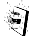
Fig. 1 illustrates the perspective view of machine frame system embodiment;
Fig. 2 illustrates the embodiment of machine frame system control layout;
Fig. 3 illustrates the sketch map of the first method embodiment;
Fig. 4 illustrates the sketch map of the second method embodiment;
Fig. 5 illustrates the vertical view of the data center that comprises many passageways machine frame system;
Fig. 6 a and 6b illustrate two exemplary servers frames that can be used in the embodiment that realizes machine frame system;
Fig. 7 illustrates the passageway that comprises foot level grill and the photo of two parallel rack rows;
Fig. 8 illustrates the unseparated machine frame system layout in hot and cold passageway;
Fig. 9 illustrates unseparated another machine frame system layout in hot and cold passageway; And
Figure 10 illustrates the chart that illustrates the load test result.
Embodiment
Fig. 1 illustrates the perspective view of the embodiment of machine frame system 100.Machine frame system 100 is accommodated in the data center room (not shown), and this data center room can comprise other machine frame systems in addition.
As shown in Figure 1, passageway 120 is sealed to basically all coolants that are fed to passageway 120 and passes frame 105.In other words, except through the frame 105, coolant is prevented to leave passageway 120 along other directions basically.Should be noted that thus, do not require the sealing fully (this also is impossible technically under reasonably technology is made great efforts) in passageway 120.In other words, the specific leakage of coolant is permissible under many circumstances, as long as this leakage can not reduce cooling effectiveness basically.
In the embodiment shown in fig. 1, some containment members are provided, are used for part sealing passageway 120, passageway in the frame cabinet that is not received frame 105 125,130 restrictions.Particularly, cladding element 135 in the passageway 120 end sealing passageway 120.Cladding element 120 is by processing such as transparent materials such as acrylic glasses, and allows to get into passageway 120 from the light of data center's illumination.Cladding element 135 comprises side direction spacing element 140,145, thereby open with the plane separation that upper end two cabinets 125,130 limits on the plane that is limited cladding element 120.
The containment member in sealing passageway 120 comprises two side direction termination element 150,155 in addition.Termination element 150,155 is configured to revolving door (swing door), is used to allow the maintenance personal to get into and leave passageway 120.Should be noted that one of side direction termination element 150,155 can be replaced by the cabinet that holds one or more frame 105.And, also can use such as interchangeable doors such as sliding doors.
Supply with passageway 120 such as coolants such as air through the floor (that is, from the bottom) in passageway.For this reason, raised floor system 160 is provided.Raised floor system 160 limits pipeline 165 between the lower plane 170 of this raised floor system 160 and last plane 175.As shown in Figure 1, frame cabinet 125,130 and the passageway 120 that is limited to therebetween are positioned on the plane 175.
The last plane 175 of raised floor system 160 comprises a plurality of openings (not shown in Fig. 1), is used for passageway 120 fluids are connected to pipeline 165.Supply to the coolant (shown in arrow 180) of pipeline 165 thereby can get into passageway 120.Because the containment member in sealing passageway 120, the coolant that gets into passageway 120 can only leave passageway 120 through frame 105, shown in arrow 185.Particularly, the privately owned media transporter of electrical equipment that is arranged in the installing space of frame 105 will get into the coolant in passageway 120 and carry through frame 105.Carry the heat heating that the coolant through frame 105 distributes by electrical equipment thus and leave frame 105, shown in arrow 190.
Heated cooling medium leaves the path of frame 105 and can leave the heated cooling medium (with optionally drying) of frame 105 and supply to pipeline 165 once more and closure through the medium that will cool off (with the back of optionally drying) through cooling.Should be noted that in other embodiments, the media flow path does not need closure.In this embodiment, the heated cooling medium that leaves frame 105 can be transported to surrounding environment from data center simply.
Clearly, the parameter of the coolant through pipeline 165 supply must be tightly controlled, and enough effectively distributes to guarantee the heat energy that electrical equipment produces, thereby prevents any undesirable heat history of appearance frame 105 in.On the other hand, be apparent that the too much adjusting (for example, too much cooling) that avoid the coolant parameter is with energization efficient.
In order effectively to control one or more parameters of the coolant that is fed to passageway 120, checkout gear 195 is provided at the top in passageway 120.Checkout gear 195 comprises the bleeding opening that is arranged in spacing element 145, and near the transducer (placement of bleeding opening and transducer will be described in detail with reference to Fig. 2 after a while) of this bleeding opening.
Can have fixing or adjustable diameter scope, for example 10cm
2With 500cm
2Between any numerical value (for example, at 80cm
2With 200cm
2Between) bleeding opening be provided for and make coolant 120 release and make surrounding medium get into passageway 120 from the passageway.In other words, according to the surrounding environment in passageway 120 and the pressure reduction between the passageway 120, coolant will leave passageway 120 through bleeding opening, and perhaps surrounding medium will get into passageway 120 through bleeding opening.Be provided near the transducer of bleeding opening and be configured to confirm media flow direction through bleeding opening.Therefore, the media flow direction indication of sensor or represent the weather conditions of the relevant coolant in the passageway 120.Therefore, according to the media flow direction of sensor, one or more parameters of coolant can be controlled, to allow to be installed in the Energy Efficient cooling of the electrical equipment in the frame 105.
Hereinafter, the schematic control chart that combines Fig. 2 is discussed an exemplary embodiment based on the parameter of checkout gear 195 control coolants.In specific embodiment shown in Figure 2, will be used to represent same or analogous element with Reference numeral identical among Fig. 1.
Control embodiment as shown in Figure 2 is based on the closed circulation path of coolant.This closed circulation path comprises that stream unit 205 falls at least one that be positioned at data center room, and this data center room is also held passageway 120.In alternative embodiment, keep fluid to be communicated with if fall stream unit 205 with similar fashion shown in Figure 2 and room, then fall stream unit 205 and also can be positioned at outside this room.
Falling stream unit 205 and comprise two special-purpose members that are arranged in single housing, is weather control unit 210 on the one hand promptly, is coolant conveyer 215 on the other hand.Weather control unit 210 is so-called coolers, and it is attached to cold feed pipe 220 and removes pipe 225 with hot water.Cold water through managing 220 supplies can have about 5 to 15 ℃ temperature (for example, between 11 to 13 ℃).Can have about 12 to 22 ℃ temperature (for example, between 16 to 19 ℃) through managing 225 hot water that remove.
Pass surrounding medium and the cold water thermo-contact and the cooling thus of weather control unit 210.Simultaneously, cold water is heated and removes pipe 225 through hot water and removes from weather control unit 210.Selectively, surrounding medium experiences the step of drying in addition in weather control unit 210.
In the embodiment shown in Figure 2, the control of coolant temperature is carried out independently.In other words, control unit 240 just works to the signal that temperature sensor 235 generates.In other embodiments, control unit 240 can be in addition or is replacedly considered the signal of shown in Figure 2 and one or more other transducers of discussing hereinafter.
As stated, the surrounding medium that is cooled off by weather control unit 210 is transferred device 215 and orders about in the entering pipeline 165.Conveyer 215 is configured to fan, its speed-controllable system, thus under the control of nonshared control unit 250, regulate the flow velocity (medium velocity) of the coolant be fed to pipeline 165.During normal running, conveyer 215 can 1~3m/s (for example, at about 1.5~2.2m/s) speed drive coolant.
In order to realize the expection flow velocity of coolant, required medium velocity depends on the height of pipeline 165, and coolant is driven to passageway 120 from falling stream unit 205 along pipeline 165.Above-mentioned medium velocity value is corresponding to the nominal duct height of about 400~600mm.Under the situation of smaller conduit height (for example 150mm), speed possibly need to increase, and under the situation than large pipeline height (for example 800mm), speed possibly reduce.Substantially, the height of medium velocity and pipeline 165 is chosen for the pressure mediums that make in the pipeline 165 and compares lowly with the pressure medium in the data center outward of passageway 120, for example is no more than 20pa (for example being no more than 10pa).
As shown in Figure 2, order about through pipeline 165 (with the speed of about 1.7m/s with data center in pressure compare increase pressure less than 10pa) coolant through the 255 entering passageways 120 of the opening in the last floor level 175.In passageway 120, can keep being generally 22~26 ℃ medium temperature thus, this is starkly lower than 32~38 ℃ ambient temperature.Shown in the arrow among Fig. 2, the coolant that gets into passageway 120 is transported to 120 outsides, passageway by the privately owned media transporter of electrical equipment, is heated during hot in absorbing electrical equipment simultaneously.Heated cooling medium composing environment medium, this surrounding medium will flow back to and fall stream unit 205, form closed flow circuits thus.
Referring to Fig. 2, checkout gear 195 comprises the bleeding opening 195A that is positioned at 120 tops, passageway and is positioned near the temperature sensor 195B of bleeding opening 195A.Be positioned at passageway 120 although temperature sensor 195B is shown, temperature sensor 195B replacedly can be positioned at outside bleeding opening 195A or the passageway 120, but close enough bleeding opening 195A, to detect media flow through bleeding opening 195A.Although in the embodiment shown in Figure 2, transducer 195B is configured to temperature sensor, it is understandable that, also can use other sensor types that can confirm through the media flow direction of bleeding opening 195A.
Hereinafter, will the control that be arranged in the conveyer 215 that falls stream unit 205 be described in more detail with reference to the flow chart 300 of Fig. 3.
Referring to the flow chart 300 of Fig. 3, originate in about the control operation of conveyer 215 coolant is fed to passageway 120 (step 302).Coolant will be filled passageway 120 thus from the bottom, arrive cladding element 135 (and temperature sensor 195B) up to it.Because all by the sealing (see figure 1), therefore all cooling media through opening 255 entering passageways 120 will pass frame 105 and can be used for making the heat in the electrical equipment that is installed in frame 105 effectively to distribute thus basically at side direction and its top in passageway 120.
If the equipment in the frame 105 need distribute more heat (needing more coolings thus), then the privately owned media transporter of this equipment 120 is ordered about more coolant through frame 105 from the passageway.Therefore, the pressure in the passageway 120 will reduce with respect to surrounding environment a little.Because this pressure in the passageway 120 reduces, the thermal environment medium will be sucked in the passageway 120 (step 304) through bleeding opening 195A.The media flow direction of passing through bleeding opening 195A that forms is thus detected (step 306) with the form that temperature increases by transducer 195B.Particularly, be drawn into bleeding opening 120 and pass temperature that the surrounding medium of temperature sensor 195B has reduce than the pressure in the passageway 120 before near temperature sensor 195B the environment of leading coolant high.
The temperature of temperature sensor 195B position raises and will be detected by control unit 250 (for example, through the predetermined temperature set point derived with the Current Temperatures set point of being obtained by control unit 240 relatively), and can be interpreted into and need more coolant 120.Therefore, control unit 250 control conveyers 215 are so that medium velocity (and flow velocity) increases.Therefore, more coolant is ordered about through pipeline 165 in the per time unit.Because the pressure in the passageway 120 reduces (it causes surrounding medium to pass through bleeding opening 195A entering passageway 120), so more coolants flow into passageway 120.
With order about the coolant that leaves passageway 120 through frame 105 by privately owned media transporter and compare; In case coolants slightly many in the time per unit are introduced into passageway 120, then the coolant level in the passageway 120 will be elevated to the position of temperature sensor 195B once more gradually.Simultaneously, the pressure reduction between passageway 120 and the surrounding environment will reduce, up to there not being more surrounding medium to be drawn in the passageway 120 through bleeding opening 195A.In other words, temperature sensor 195B will finally be arranged in the surrounding environment of coolant once more, and the temperature that forms thus descends by control unit 250 detections.Particularly, control unit 250 can confirm that enough coolants supply to passageway 120 and begin to reduce gradually the speed (and flow velocity) through the coolant of pipeline 165, up to arriving the specified temp set point that is associated with temperature sensor 195B once more.
High several degrees centigrade (for example, 1 to 8 ℃) of the mean temperature of the coolant in the above-mentioned comparable entering of this desired temperature passageway 120.For example, the coolant temperature (measuring) that can regulate based on controlled unit 240 of desired temperature and dynamically limiting temperature sensor 235.The advantage of set point is to be not limited to begin to increase flow velocity from the certain nominal flow velocity by the control situation that control unit 250 is realized, and can reduce beginning from initial flow rate.Therefore; Have less power consumption (and if their privately owned media transporter 120 order about less coolant through frame 105 from the passageway thus) if be arranged in the electrical equipment of frame, then the detected temperature of temperature sensor 195B can reduce with respect to desired temperature.But this temperature reduces Be Controlled unit 250 and is construed to too much coolant and is fed to passageway 120, and can reduce coolant is driven to (that is medium velocity) in the pipeline 165.
In optional control situation, consider the signal that another temperature sensor 260 generates during control unit 250 control conveyers 215 in addition.Particularly, control unit 250 can respond on the one hand temperature sensor 260 detected temperature and on the other hand the temperature difference between the detected temperature of temperature sensor 195B control conveyer 215.For example; Control unit 250 can be configured to control the flow velocity of coolant; If the feasible temperature that is detected because of temperature sensor 195B by the predetermined temperature difference between the temperature of two temperature sensor 195B, 260 measurements respectively raises and reduces, the then flow velocity of coolant increase, vice versa.
Hereinafter, will another embodiment that be used to control conveyer 215 be described with reference to the flow chart 400 of Fig. 4.Control embodiment shown in Figure 4 can carry out with the control embodiment that the above Fig. 3 of combination discusses or as its replaceable mode simultaneously.
In first step 402, before coolant got into passageway 120 and frame 105, the temperature of coolant (property parameter as an example) remained on predetermined temperature value.As stated, the step that coolant temperature is remained on predetermined value is carried out by weather control unit 210 under the control of control unit 240, and said control unit 240 response temperature transducers 235 detected temperature are regulated valve 245.
In step 404, coolant is transferred device 215 and pushes through pipeline 165 and get into passageway 120 and arrive the medium supply side of frame 105.Then, in step 406, can confirm whether be different from circulation through the coolant of conveyer 215 through the circulation (turnover) of the coolant of frame 105.
In further step 408, conveyer 215 is controlled according to the circulation difference of in step 406, confirming.This for example controls, and purpose can be to make circulation difference to minimize or circulation difference is remained on predetermined value.
Should be noted that, step 402 to 408 in normal conditions by simultaneously and repeat.And as stated, any change in circulation difference and the circulation difference can confirm that maybe the signal that any other transducer of the flow direction through bleeding opening 195A provides detects based on temperature sensor 195B.
Because Fig. 1 is to the control method of relevant conveyer 215 shown in Figure 4, the power consumption of conveyer 215 can need along with the power equipment of speed in being installed in frame 105 of its fan optionally to descend under the situation of less cooling and reduce.
Although the foregoing description only comprises single checkout gear 195, it will be appreciated that two or more this checkout gears 195 can be positioned at the spaced position on 120 tops, passageway.In this case, the temperature sensor 195B of each checkout gear 195 will be electrically connected to control unit 250.Control unit 250 then can be based on carrying out its control task by the detected maximum temperature value of arbitrary temp transducer 195B.And, should be further appreciated that the quantity in the passageway 120 that is connected to pipeline 165 can increase as required.Thus, will be with reference to schematic machine frame system layout shown in Figure 5.Once more, identical Reference numeral will be used to represent same or analogous parts.
According to machine frame system layout shown in Figure 5, four parallel passageways 120 are provided, each passageway 120 limits (in Fig. 5, only specifically expressing two row) two parallel rack rows 110,115.Independent passageway 120 all is connected to identical pipeline (seeing the Reference numeral 165 of Fig. 1 and Fig. 2).Every capable frame 110,115 comprises 9 or 10 rack units.Each passageway 120 comprises at least one checkout gear 195.
Main control unit is configured to any checkout gear 195 detected maximum temperatures of Response Distribution on each passageway 120 and carries out its control operation.According to the cooling requirement, main control unit falls the stream unit with each and connects, breaks off or switch to run-up mode.In addition, main control unit control be switched on according to detected maximum temperature (maximal rate 30 to 100% between scope in) the fan speed that flows the conveyer that unit 205 is associated falls.Although main control unit is the overall flow rate of centralized control coolant thus, each falls stream unit 205 can be independently and control the temperature and humidity of coolant of falling stream unit 205 through each partly.Each temperature and humidity control of falling the stream unit can be based on the desired temperature that obtains from main control unit.
The The whole control notion is identical with the control concept that above combination Fig. 1 to Fig. 4 discusses.In other words, in first step, will compare by any detected maximum temperature and the desired temperature in the checkout gear 195 that distributes.In concrete example, desired temperature is configured to the desired temperature (see figure 2) high 1 to 6 ℃ (for example 2~4 ℃) that is suitable for than control unit 240.If be lower than the desired temperature that is suitable for by main control unit by the detected maximum temperature of arbitrary temp transducer 195B, then this expression is fallen stream unit 205 too many coolant is sent to each passageway 120.Correspondingly, the flow velocity of coolant will reduce.On the other hand, if maximum temperature is higher than desired temperature, then this can be regarded as the expression fall stream unit 205 enough coolants are not sent to each passageway 120.Correspondingly, the flow velocity of coolant will increase.As stated, the possible measure of control flow velocity comprises that being switched on or switched off each falls stream unit 205, and the fan speed of falling stream unit 205 of control on.The control strategy that is suitable for by controller shown in Figure 2 240,250 and main control unit comprises that this is as the known PI control of prior art.
Fig. 6 illustrates the embodiment of frame 105, and this frame 105 comprises a plurality of installing spaces that are used to hold the pay(useful) load that comprises electrical equipment.Particularly, Fig. 6 a illustrates sky frame 105, and it can constitute the basis of the machine frame system of above combination Fig. 1 to Fig. 5 argumentation.Frame 105 untapped installing spaces can be covered by the backup panel shown in Fig. 6 b.Backup panel guarantees that the coolant that is fed to passageway 120 can not spill frame 105.Should notice once more at this, not need 100% sealing to allow effective cooling down operation.
Fig. 7 illustrates the sketch map on the floor in passageway 120.As shown in Figure 7, the floor is covered by grid 705 fully.Grid 705 has big open surface area.Particularly, about 90% of grid 705 surface area can see through coolant.Owing to use grid 705 as shown in Figure 7; Only to passageway 120, this allows to fall the conveyer low-speed running in the stream unit to the very little relatively pressure reduction between the surrounding environment in needs (on the one hand) pipeline 165 and (on the other hand) passageway 120 equally with the coolant effective supply.As stated, just enough under many circumstances less than the pressure reduction of 10pa.
The cooling means of the various cooling means ratios that this paper discusses such as Fig. 8 and prior art shown in Figure 9 provides tangible advantage.Fig. 8 illustrates the unseparated machine frame system layout in hot and cold passageway.This machine frame system layout is supported in the data center of the ventilating path in the data center very general at the genetic system and specifically not being suitable for of trooping.Can know that by figure a plurality of zones are arranged in ellipse, these a plurality of zones, mix from the fresh coolant of ground Plate supplying and the heated cooling medium that leaves frame.This mixing obviously reduces the cooling effectiveness of data center.Fig. 9 illustrates another modification of the machine frame system layout in the data center, and this moment, separated in hot and cold passageway.Shown in ellipse, the zone that still has fresh coolant and heated cooling medium to mix.
The operating parameter that demonstration is used for the machine frame system layout of Fig. 8 and Fig. 9 is compared with operating parameter shown in Figure 2, is apparent that, the cooling means that this paper discusses can be used littler medium velocity and pressure reduction.In addition, leave fall stream unit 205 coolant needn't be cooled with genetic method as many, this has also increased total cooling effectiveness.
The improved cooling effectiveness of the technology that this paper discusses also is shown in the chart of Figure 10.Be apparent that according to Figure 10 the temperature in the top in passageway 120 and the bottom section (in Figure 10, being called " cold passageway ") can be maintained at below 25 ℃ the critical temperature well, though electrical load and required heat of distributing obviously increase also be like this.Any increase of electrical load only causes data room (being called as " hot passageway " among Figure 10) heating outside the passageway 120, and can not influence the cold channel temp of crossing.
Therefore, Figure 10 illustrates the higher cooling effectiveness of method generation that this paper discusses.Simultaneously, fall stream unit 205 (particularly conveyer 215) cost of energy and running time obviously reduce with respect to conventional art.As further side effect, the fan speed of conveyer 215 can reduce under most of operating conditions, and this causes the noise in the data center obviously to reduce.
Although described the present invention with reference to specific embodiment, those skilled in the art will recognize that to the invention is not restricted to the specific embodiment that this paper describes and illustrates.Therefore, it is understandable that it is exemplary that the disclosure is merely.Therefore, the present invention is only limited the scope of accompanying claims.
Claims (22)
1. a machine frame system (100) comprising:
A plurality of frames (105), these a plurality of frames (105) are arranged between it to form at least one passageway (120), and wherein, said passageway (120) are sealed to basically all coolants that are fed to said passageway (120) and pass said frame (105);
Be used to make said coolant to release and make surrounding medium can get into the bleeding opening (195A) of said passageway (120) from said passageway (120);
Be used for confirming first sensor (195B) through the media flow direction of said bleeding opening (195A); And
Controlling organization, this controlling organization are suitable for being fed to according to the signal controlling that said first sensor (195A) generates at least one parameter of the said coolant in said passageway (120), the said media flow direction of said signal indication.
2. system according to claim 1, wherein, first sensor (195B) is near said bleeding opening (195A).
3. system according to claim 2; Wherein, Said first sensor (195B) is selected from the set that comprises temperature sensor, air propeller and sail console switch, and said sail console switch is constructed to sail and is placed with and obtains medium and console switch is rotated with the corresponding direction of said media flow direction in the edge.
4. according to each described system of aforementioned claim, wherein, said bleeding opening (195A) is positioned at the top of said passageway (120).
5. system according to claim 1, wherein, said at least one parameter is selected from the set of the temperature, humidity and the flow velocity that comprise said coolant.
6. system according to claim 1 further comprises at least one conveyer (215) that is used for said coolant is transported to said passageway (120).
7. system according to claim 6, wherein, said at least one conveyer (215) is suitable for being fed to according to the signal controlling that said first sensor (195B) generates the flow velocity of the said coolant in said passageway (120).
8. system according to claim 7 further comprises at least one weather control unit (210), is used at least one of temperature and humidity that control is fed to the said coolant in said passageway (120).
9. system according to claim 8, wherein, at least one in the temperature and humidity of the said coolant of signal controlling that said at least one weather control unit (210) is suitable for generating according to said first sensor (195B).
10. system according to claim 9; Further comprise at least one second transducer (235; 260); Wherein, at least one in said controlling organization, said conveyer (215) and the said weather control unit (210) further is controlled according to the signal that said second transducer (235,260) generates.
11. system according to claim 10, wherein, said at least one second transducer (235,260) is away from said bleeding opening (195A) and the said first sensor (195B) at least one.
12. system according to claim 1 further is included in the cladding element (135) in the said passageway of end sealing (120).
13. system according to claim 1 further is included in one or more termination element (150,155) in the said passageway of one or more lateral end seal (120).
14. system according to claim 1 further comprises the grid (705) that is used for said coolant is fed to said passageway (120), said grid (705) is positioned at the floor of said passageway (120).
15. system according to claim 1 further comprises the pipeline (165) that is configured to said coolant is fed to said passageway (120).
16. system according to claim 15, wherein, said pipeline (165) is configured to said coolant is fed to a plurality of passageways (120).
17. system according to claim 15, wherein, said pipeline (165) is positioned at said a plurality of frame (105) below.
18. system according to claim 1; Wherein, In the said frame (105) each has: be used for said coolant is fed to the supply side of said frame (105) and is used for said coolant is removed and relative with the said supply side side that removes from said frame (105); Wherein, the said supply side of said frame (105) is arranged to the inside in the face of said passageway (120).
19. system according to claim 1 further comprises the electrical equipment that needs cool off, said electrical equipment is arranged in the installing space of said frame (105).
20. system according to claim 1 comprises that further said passageway is positioned at housing wherein, said housing is suitable for the circulating path of closed said coolant.
21. a method that is used for the weather conditions of definite machine frame system (100), said machine frame system (100) comprises a plurality of frames (105), and these a plurality of frames (105) are arranged between it, form passageway (120), and said method comprises:
Coolant is fed to said passageway (120), and wherein, said passageway (120) are sealed to basically all said coolants that are fed to said passageway (120) and pass said frame (105);
Bleeding opening (195A) is provided, is used to make said coolant to release and make surrounding medium can get into said passageway (120) from said passageway (120);
Confirm media flow direction through said bleeding opening (195A); And
Be fed at least one parameter of the said coolant in said passageway (120) according to said media flow direction control.
22. method according to claim 21, wherein, said at least one parameter is selected from the set of the temperature, humidity and the flow velocity that comprise said coolant.
Applications Claiming Priority (3)
| Application Number | Priority Date | Filing Date | Title |
|---|---|---|---|
| EP07021813A EP2059105B1 (en) | 2007-11-09 | 2007-11-09 | System and method for climate control |
| EP07021813.6 | 2007-11-09 | ||
| PCT/EP2008/004871 WO2009059649A1 (en) | 2007-11-09 | 2008-06-17 | Rack system and method of determining a climate condition thereof |
Publications (2)
| Publication Number | Publication Date |
|---|---|
| CN101861764A CN101861764A (en) | 2010-10-13 |
| CN101861764B true CN101861764B (en) | 2012-06-06 |
Family
ID=39471748
Family Applications (2)
| Application Number | Title | Priority Date | Filing Date |
|---|---|---|---|
| CN2008801154847A Expired - Fee Related CN101861764B (en) | 2007-11-09 | 2008-06-17 | Rack system and method of determining a climate condition thereof |
| CN200880115483A Pending CN101855952A (en) | 2007-11-09 | 2008-11-10 | The method of the climate condition of machine frame system and definite machine frame system |
Family Applications After (1)
| Application Number | Title | Priority Date | Filing Date |
|---|---|---|---|
| CN200880115483A Pending CN101855952A (en) | 2007-11-09 | 2008-11-10 | The method of the climate condition of machine frame system and definite machine frame system |
Country Status (11)
| Country | Link |
|---|---|
| US (2) | US8690651B2 (en) |
| EP (5) | EP2421349B1 (en) |
| JP (2) | JP5033239B2 (en) |
| CN (2) | CN101861764B (en) |
| AT (4) | ATE540566T1 (en) |
| AU (2) | AU2008324508B2 (en) |
| BR (1) | BRPI0817381A2 (en) |
| DE (4) | DE202007019005U1 (en) |
| ES (4) | ES2595802T3 (en) |
| RU (2) | RU2444777C2 (en) |
| WO (3) | WO2009059649A1 (en) |
Families Citing this family (73)
| Publication number | Priority date | Publication date | Assignee | Title |
|---|---|---|---|---|
| US8469782B1 (en) | 2007-06-14 | 2013-06-25 | Switch Communications Group, LLC | Data center air handling unit |
| US9622389B1 (en) | 2007-06-14 | 2017-04-11 | Switch, Ltd. | Electronic equipment data center and server co-location facility configurations and method of using the same |
| US9693486B1 (en) | 2007-06-14 | 2017-06-27 | Switch, Ltd. | Air handling unit with a canopy thereover for use with a data center and method of using the same |
| US8523643B1 (en) | 2007-06-14 | 2013-09-03 | Switch Communications Group LLC | Electronic equipment data center or co-location facility designs and methods of making and using the same |
| US9823715B1 (en) * | 2007-06-14 | 2017-11-21 | Switch, Ltd. | Data center air handling unit including uninterruptable cooling fan with weighted rotor and method of using the same |
| US10028415B1 (en) | 2007-06-14 | 2018-07-17 | Switch, Ltd. | Electronic equipment data center and server co-location facility configurations and method of using the same |
| US9788455B1 (en) | 2007-06-14 | 2017-10-10 | Switch, Ltd. | Electronic equipment data center or co-location facility designs and methods of making and using the same |
| JP5308750B2 (en) * | 2008-03-26 | 2013-10-09 | 株式会社Nttファシリティーズ | Rack air conditioning system |
| GB2464354B (en) * | 2009-03-13 | 2011-06-08 | 4Energy Ltd | Equipment enclosure |
| JP5402306B2 (en) * | 2009-06-25 | 2014-01-29 | 富士通株式会社 | Air conditioning system, air conditioning control method, and air conditioning control program |
| NL1037125C2 (en) * | 2009-07-16 | 2011-01-20 | J C A Van De Pas Holding B V | AIR TREATMENT BOX, ITS APPLICATION FOR COOLING A SPACE AND A METHOD FOR COOLING A SPACE THEREOF. |
| JP5597957B2 (en) * | 2009-09-04 | 2014-10-01 | 富士通株式会社 | Data center, cooling system, and cooling method for IT equipment |
| JP5268855B2 (en) * | 2009-10-09 | 2013-08-21 | ヤフー株式会社 | Rack and information processing equipment accommodation |
| EP2362721A1 (en) * | 2010-02-26 | 2011-08-31 | TeliaSonera AB | Method and system for cooling apparatus racks |
| JP5102323B2 (en) * | 2010-04-02 | 2012-12-19 | 中央電子株式会社 | Electronic equipment storage rack |
| WO2011140463A1 (en) * | 2010-05-06 | 2011-11-10 | Eaton Corporation | Aisle enclosure system |
| US8628158B2 (en) | 2010-05-13 | 2014-01-14 | Panduit Corp. | Aisle containment system |
| US8628154B2 (en) | 2010-05-13 | 2014-01-14 | Panduit Corp. | Aisle containment system |
| US8628153B2 (en) | 2010-05-13 | 2014-01-14 | Pandult Corp. | Aisle containment system |
| GB201008825D0 (en) * | 2010-05-26 | 2010-07-14 | Bripco Bvba | Data centre cooling system |
| KR101147462B1 (en) * | 2010-08-05 | 2012-05-21 | (주) 지트시스템 | Cooling of rack structures |
| US8961278B2 (en) * | 2010-08-13 | 2015-02-24 | Schneider Electric It Corporation | Single rack cold air containment |
| DE102010037204B4 (en) | 2010-08-27 | 2014-03-27 | Correct Power Institute Gmbh | cooler |
| US9332678B2 (en) | 2010-09-30 | 2016-05-03 | International Business Machines Corporation | Cold air containment system in a data centre |
| US8914155B1 (en) | 2010-10-28 | 2014-12-16 | Hewlett-Packard Development Company, L.P. | Controlling fluid flow in a data center |
| JP5085716B2 (en) * | 2010-11-02 | 2012-11-28 | 株式会社東芝 | Air conditioning system for server room management, server management system using the same, and air conditioning control method |
| US9655259B2 (en) | 2011-12-09 | 2017-05-16 | Chatsworth Products, Inc. | Data processing equipment structure |
| US9560777B2 (en) | 2010-11-08 | 2017-01-31 | Chatsworth Products, Inc. | Door closer mechanism for hot/cold aisle air containment room |
| TW201221042A (en) * | 2010-11-12 | 2012-05-16 | Hon Hai Prec Ind Co Ltd | Noise reduction apparatus, method, and container data center including the same |
| US8641492B2 (en) * | 2010-12-27 | 2014-02-04 | Gary Meyer | Directional flow raised floor air-grate |
| US8534119B2 (en) | 2010-12-30 | 2013-09-17 | Schneider Electric It Corporation | System and method for air containment zone air leakage detection |
| DE102011000638B4 (en) | 2011-02-10 | 2014-04-24 | Rittal Gmbh & Co. Kg | Method and device for controlling and monitoring an air conditioning system for data processing systems |
| DE102011006779B4 (en) | 2011-04-05 | 2017-06-08 | Siemens Aktiengesellschaft | Arrangement for cooling electronic components |
| US9195243B2 (en) | 2011-05-24 | 2015-11-24 | Aten International Co., Ltd. | System and method of safe and effective energy usage and conservation for data centers with rack power distribution units |
| JP2012248136A (en) * | 2011-05-31 | 2012-12-13 | Sohki:Kk | Server temperature management system or server temperature management method |
| US20130078901A1 (en) * | 2011-09-23 | 2013-03-28 | Kingspan Holdings (Irl) Limited | Cooling systems and methods for data centers |
| US10206311B2 (en) * | 2011-10-21 | 2019-02-12 | Rittal Gmbh & Co. Kg | Cooling circuit system, in particular to be used in a data center, and controlling method thereof |
| NL2007676C2 (en) * | 2011-10-31 | 2013-05-06 | Hiensch Engineering B V | SYSTEM FOR COOLING ELECTRONIC EQUIPMENT. |
| CA2856695C (en) * | 2011-11-22 | 2020-06-09 | Le Groupe S.M. Inc. | Data center cooling system |
| JP5842936B2 (en) * | 2012-01-30 | 2016-01-13 | 富士通株式会社 | Air conditioning system |
| US11246231B2 (en) | 2012-02-10 | 2022-02-08 | Chatsworth Products, Inc. | Door closer mechanism for hot/cold aisle air containment room |
| EP2663172A1 (en) * | 2012-05-11 | 2013-11-13 | eCube Computing GmbH | Method for operating a data centre with efficient cooling means |
| JP5976424B2 (en) * | 2012-07-04 | 2016-08-23 | 富士通株式会社 | Local air conditioning system and its control device |
| US9144181B2 (en) * | 2012-11-09 | 2015-09-22 | Facebook, Inc. | Cooling computing assets in a data center using hot and cold stacks |
| JP6090715B2 (en) * | 2013-02-15 | 2017-03-08 | パナソニックIpマネジメント株式会社 | Server cooling system |
| KR101278633B1 (en) * | 2013-02-25 | 2013-06-25 | 김종선 | Heat dissipation system for a server |
| US9668375B2 (en) * | 2013-03-15 | 2017-05-30 | Yahoo! Inc. | Atmospheric cooling of servers in a data center |
| US9198331B2 (en) | 2013-03-15 | 2015-11-24 | Switch, Ltd. | Data center facility design configuration |
| RU2592883C2 (en) * | 2013-08-30 | 2016-07-27 | Общество С Ограниченной Ответственностью "Яндекс" | Cooling system, method of operating such system and backup cooling device |
| JP5657153B1 (en) * | 2014-02-12 | 2015-01-21 | ニッキャビ株式会社 | Air-conditioning mechanism for racks for heating equipment |
| CN104883829A (en) * | 2014-02-28 | 2015-09-02 | 鸿富锦精密工业(武汉)有限公司 | Cabinet system |
| US9999160B1 (en) * | 2014-03-31 | 2018-06-12 | Emc Corporation | Method and system for air contamination analysis for free air cooled data centers |
| US9943011B2 (en) * | 2014-09-10 | 2018-04-10 | Panduit Corp. | Cooling control for data centers with cold aisle containment systems |
| US10257268B2 (en) | 2015-03-09 | 2019-04-09 | Vapor IO Inc. | Distributed peer-to-peer data center management |
| US10833940B2 (en) | 2015-03-09 | 2020-11-10 | Vapor IO Inc. | Autonomous distributed workload and infrastructure scheduling |
| US10039211B2 (en) | 2015-03-09 | 2018-07-31 | Vapor IO Inc. | Rack for computing equipment |
| US10404523B2 (en) | 2015-03-09 | 2019-09-03 | Vapor IO Inc. | Data center management with rack-controllers |
| CN107535070B (en) | 2015-03-09 | 2019-11-29 | 纬波里奥股份有限责任公司 | For calculating the rack of equipment |
| US10159167B2 (en) | 2015-09-16 | 2018-12-18 | Rack Cooling Technologies LLC | Cooling apparatus with a control system for cooling microprocessor based equipment |
| CN108141986B (en) * | 2015-09-21 | 2020-07-03 | Abb瑞士股份有限公司 | Cooling device, e.g. for cooling a converter valve hall |
| US10454772B2 (en) | 2015-10-30 | 2019-10-22 | Vapor IO Inc. | Compact uninteruptable power supply |
| US10548244B2 (en) * | 2015-10-30 | 2020-01-28 | Schneider Electric It Corporation | Data center air containment system |
| US9985842B2 (en) | 2015-10-30 | 2018-05-29 | Vapor IO Inc. | Bus bar power adapter for AC-input, hot-swap power supplies |
| JP6515794B2 (en) * | 2015-12-03 | 2019-05-22 | 富士通株式会社 | Data center |
| US10965525B1 (en) | 2016-06-29 | 2021-03-30 | Amazon Technologies, Inc. | Portable data center for data transfer |
| US10398061B1 (en) * | 2016-06-29 | 2019-08-27 | Amazon Technologies, Inc. | Portable data center for data transfer |
| US9795062B1 (en) | 2016-06-29 | 2017-10-17 | Amazon Technologies, Inc. | Portable data center for data transfer |
| US20180077819A1 (en) | 2016-09-14 | 2018-03-15 | Switch, Ltd. | Ventilation and air flow control |
| US10306810B1 (en) * | 2016-11-10 | 2019-05-28 | Equinix, Inc. | Hot-aisle cooling |
| US11076509B2 (en) | 2017-01-24 | 2021-07-27 | The Research Foundation for the State University | Control systems and prediction methods for it cooling performance in containment |
| AU2018346347A1 (en) * | 2017-10-06 | 2020-04-09 | Taylor Commercial Foodservice, LLC. | Matrix configured grill apparatus |
| US10306809B1 (en) * | 2017-12-13 | 2019-05-28 | Oath Inc. | Server rack integrated with cold air delivery |
| CN109114717A (en) * | 2018-09-26 | 2019-01-01 | 吴磊 | A kind of assembled computer room with heat sinking function |
Citations (3)
| Publication number | Priority date | Publication date | Assignee | Title |
|---|---|---|---|---|
| US20030050003A1 (en) * | 2001-09-07 | 2003-03-13 | International Business Machines Corporation | Air flow management system for an internet data center |
| US20060168975A1 (en) * | 2005-01-28 | 2006-08-03 | Hewlett-Packard Development Company, L.P. | Thermal and power management apparatus |
| US20060260338A1 (en) * | 2005-05-17 | 2006-11-23 | Vangilder James | Cold aisle isolation |
Family Cites Families (19)
| Publication number | Priority date | Publication date | Assignee | Title |
|---|---|---|---|---|
| US6034873A (en) * | 1998-06-02 | 2000-03-07 | Ericsson Inc | System and method for separating air flows in a cooling system |
| EP1181852B1 (en) * | 1999-06-01 | 2003-03-26 | Volker Dalheimer | Housing system for housing electronic components, especially a flat desktop pc or multimedia housing |
| US6574104B2 (en) * | 2001-10-05 | 2003-06-03 | Hewlett-Packard Development Company L.P. | Smart cooling of data centers |
| US6775997B2 (en) * | 2002-10-03 | 2004-08-17 | Hewlett-Packard Development Company, L.P. | Cooling of data centers |
| US6859366B2 (en) * | 2003-03-19 | 2005-02-22 | American Power Conversion | Data center cooling system |
| US7051946B2 (en) * | 2003-05-29 | 2006-05-30 | Hewlett-Packard Development Company, L.P. | Air re-circulation index |
| US20050023363A1 (en) * | 2003-05-29 | 2005-02-03 | Sharma Ratnesh K. | CRAC unit control based on re-circulation index |
| US7272945B2 (en) * | 2003-07-29 | 2007-09-25 | Hewlett-Packard Development Company, L.P. | Environmental condition measurement system |
| US7248942B2 (en) * | 2004-02-19 | 2007-07-24 | Hewlett-Packard Development Company, L.P. | Airflow detection system having an airflow indicating device |
| RU2284051C2 (en) * | 2004-05-17 | 2006-09-20 | Юрий Викторович Сивов | Method for building a cooling system in processor blocks of personal computers of various types and constructions, providing for application of noise reduction system in conjunction with efficient cooling of thermo-loaded components, decreased total temperature background as well as noise and vibration levels during operation of processor block in various operation modes |
| US7330350B2 (en) * | 2004-06-04 | 2008-02-12 | Cray Inc. | Systems and methods for cooling computer modules in computer cabinets |
| US7259963B2 (en) | 2004-12-29 | 2007-08-21 | American Power Conversion Corp. | Rack height cooling |
| US20070135032A1 (en) * | 2005-12-14 | 2007-06-14 | Ncr Corporation | Minimized exhaust air re-circulation around air cooled hardware cabinets |
| JP4873997B2 (en) * | 2006-05-26 | 2012-02-08 | ヤフー株式会社 | Equipment storage rack and equipment storage room air conditioning system |
| EP2036412B1 (en) * | 2006-06-01 | 2012-11-14 | Exaflop LLC | Controlled warm air capture |
| GB2446454B (en) * | 2007-02-07 | 2011-09-21 | Robert Michael Tozer | Cool design data centre |
| GB2450098B (en) * | 2007-06-12 | 2012-06-20 | Jca Technology | Cooling system |
| JP5308750B2 (en) * | 2008-03-26 | 2013-10-09 | 株式会社Nttファシリティーズ | Rack air conditioning system |
| US20100190430A1 (en) * | 2009-01-29 | 2010-07-29 | International Business Machines Corporation | Air permeable material for data center cooling |
-
2007
- 2007-11-09 ES ES11008439.9T patent/ES2595802T3/en active Active
- 2007-11-09 DE DE202007019005U patent/DE202007019005U1/en not_active Expired - Lifetime
- 2007-11-09 EP EP11008439.9A patent/EP2421349B1/en active Active
- 2007-11-09 AT AT07021813T patent/ATE540566T1/en active
- 2007-11-09 EP EP07021813A patent/EP2059105B1/en active Active
-
2008
- 2008-06-17 EP EP08759268A patent/EP2218314B1/en active Active
- 2008-06-17 AT AT08759268T patent/ATE505071T1/en not_active IP Right Cessation
- 2008-06-17 WO PCT/EP2008/004871 patent/WO2009059649A1/en active Application Filing
- 2008-06-17 RU RU2010120022/07A patent/RU2444777C2/en not_active IP Right Cessation
- 2008-06-17 JP JP2010532447A patent/JP5033239B2/en not_active Expired - Fee Related
- 2008-06-17 ES ES08759268T patent/ES2361646T3/en active Active
- 2008-06-17 CN CN2008801154847A patent/CN101861764B/en not_active Expired - Fee Related
- 2008-06-17 AU AU2008324508A patent/AU2008324508B2/en not_active Ceased
- 2008-06-17 DE DE602008006111T patent/DE602008006111D1/en active Active
- 2008-06-17 BR BRPI0817381 patent/BRPI0817381A2/en not_active IP Right Cessation
- 2008-06-17 US US12/742,003 patent/US8690651B2/en not_active Expired - Fee Related
- 2008-11-10 ES ES08846638T patent/ES2357875T3/en active Active
- 2008-11-10 JP JP2010532499A patent/JP5033240B2/en not_active Expired - Fee Related
- 2008-11-10 US US12/742,012 patent/US20110014862A1/en not_active Abandoned
- 2008-11-10 AU AU2008324374A patent/AU2008324374B2/en not_active Ceased
- 2008-11-10 AT AT08846638T patent/ATE495656T1/en not_active IP Right Cessation
- 2008-11-10 WO PCT/EP2008/009471 patent/WO2009059796A1/en active Application Filing
- 2008-11-10 DE DE602008004576T patent/DE602008004576D1/en active Active
- 2008-11-10 EP EP08847904A patent/EP2208406B1/en active Active
- 2008-11-10 RU RU2010120021/07A patent/RU2433578C1/en not_active IP Right Cessation
- 2008-11-10 ES ES08847904T patent/ES2362328T3/en active Active
- 2008-11-10 CN CN200880115483A patent/CN101855952A/en active Pending
- 2008-11-10 WO PCT/EP2008/009463 patent/WO2009059795A1/en active Application Filing
- 2008-11-10 DE DE602008006251T patent/DE602008006251D1/en active Active
- 2008-11-10 EP EP08846638A patent/EP2218313B1/en not_active Not-in-force
- 2008-11-10 AT AT08847904T patent/ATE505939T1/en not_active IP Right Cessation
Patent Citations (3)
| Publication number | Priority date | Publication date | Assignee | Title |
|---|---|---|---|---|
| US20030050003A1 (en) * | 2001-09-07 | 2003-03-13 | International Business Machines Corporation | Air flow management system for an internet data center |
| US20060168975A1 (en) * | 2005-01-28 | 2006-08-03 | Hewlett-Packard Development Company, L.P. | Thermal and power management apparatus |
| US20060260338A1 (en) * | 2005-05-17 | 2006-11-23 | Vangilder James | Cold aisle isolation |
Also Published As
Similar Documents
| Publication | Publication Date | Title |
|---|---|---|
| CN101861764B (en) | Rack system and method of determining a climate condition thereof | |
| US8844220B2 (en) | Computer room | |
| US8764528B2 (en) | Systems and methods for closed loop heat containment with cold aisle isolation for data center cooling | |
| US8072780B1 (en) | Integrated wiring system and thermal shield support apparatus for a data center | |
| US20170086333A1 (en) | Systems and methods for cooling data centers and other electronic equipment | |
| ES2311693T3 (en) | IMPROVEMENTS IN THE REFRIGERATION OF A DATA CENTER. | |
| US20130061624A1 (en) | Modular datacenter element and modular datacenter cooling element | |
| US20100248609A1 (en) | Assembly For Providing A Downflow Return Air Supply | |
| JP2008002690A (en) | Air conditioning system | |
| EP2268978A1 (en) | Apparatus and method for cooling of a substantially closed space with recirculation air | |
| CN103140122A (en) | Hot aisle containment cooling system and method | |
| EP2362721A1 (en) | Method and system for cooling apparatus racks | |
| Niemann | Hot aisle vs. cold aisle containment | |
| CN105066303A (en) | Data center computer room | |
| US11483946B2 (en) | Security panels for use in data centers | |
| Hannaford | Ten steps to solving cooling problems cause by high-density server deployment | |
| WO2011080168A2 (en) | Direct air cooling |
Legal Events
| Date | Code | Title | Description |
|---|---|---|---|
| C06 | Publication | ||
| PB01 | Publication | ||
| C10 | Entry into substantive examination | ||
| SE01 | Entry into force of request for substantive examination | ||
| C14 | Grant of patent or utility model | ||
| GR01 | Patent grant | ||
| CF01 | Termination of patent right due to non-payment of annual fee |
Granted publication date: 20120606 Termination date: 20160617 |
|
| CF01 | Termination of patent right due to non-payment of annual fee |