CN101983459A - Multiple coaxial connector - Google Patents
Multiple coaxial connector Download PDFInfo
- Publication number
- CN101983459A CN101983459A CN2009801120493A CN200980112049A CN101983459A CN 101983459 A CN101983459 A CN 101983459A CN 2009801120493 A CN2009801120493 A CN 2009801120493A CN 200980112049 A CN200980112049 A CN 200980112049A CN 101983459 A CN101983459 A CN 101983459A
- Authority
- CN
- China
- Prior art keywords
- connector
- shell
- core coaxial
- coaxial
- group
- Prior art date
- Legal status (The legal status is an assumption and is not a legal conclusion. Google has not performed a legal analysis and makes no representation as to the accuracy of the status listed.)
- Pending
Links
Images


Classifications
-
- H—ELECTRICITY
- H01—ELECTRIC ELEMENTS
- H01R—ELECTRICALLY-CONDUCTIVE CONNECTIONS; STRUCTURAL ASSOCIATIONS OF A PLURALITY OF MUTUALLY-INSULATED ELECTRICAL CONNECTING ELEMENTS; COUPLING DEVICES; CURRENT COLLECTORS
- H01R24/00—Two-part coupling devices, or either of their cooperating parts, characterised by their overall structure
- H01R24/38—Two-part coupling devices, or either of their cooperating parts, characterised by their overall structure having concentrically or coaxially arranged contacts
- H01R24/40—Two-part coupling devices, or either of their cooperating parts, characterised by their overall structure having concentrically or coaxially arranged contacts specially adapted for high frequency
- H01R24/50—Two-part coupling devices, or either of their cooperating parts, characterised by their overall structure having concentrically or coaxially arranged contacts specially adapted for high frequency mounted on a PCB [Printed Circuit Board]
-
- H—ELECTRICITY
- H01—ELECTRIC ELEMENTS
- H01R—ELECTRICALLY-CONDUCTIVE CONNECTIONS; STRUCTURAL ASSOCIATIONS OF A PLURALITY OF MUTUALLY-INSULATED ELECTRICAL CONNECTING ELEMENTS; COUPLING DEVICES; CURRENT COLLECTORS
- H01R13/00—Details of coupling devices of the kinds covered by groups H01R12/70 or H01R24/00 - H01R33/00
- H01R13/46—Bases; Cases
- H01R13/514—Bases; Cases composed as a modular blocks or assembly, i.e. composed of co-operating parts provided with contact members or holding contact members between them
-
- H—ELECTRICITY
- H01—ELECTRIC ELEMENTS
- H01R—ELECTRICALLY-CONDUCTIVE CONNECTIONS; STRUCTURAL ASSOCIATIONS OF A PLURALITY OF MUTUALLY-INSULATED ELECTRICAL CONNECTING ELEMENTS; COUPLING DEVICES; CURRENT COLLECTORS
- H01R13/00—Details of coupling devices of the kinds covered by groups H01R12/70 or H01R24/00 - H01R33/00
- H01R13/46—Bases; Cases
- H01R13/516—Means for holding or embracing insulating body, e.g. casing, hoods
- H01R13/518—Means for holding or embracing insulating body, e.g. casing, hoods for holding or embracing several coupling parts, e.g. frames
-
- H—ELECTRICITY
- H01—ELECTRIC ELEMENTS
- H01R—ELECTRICALLY-CONDUCTIVE CONNECTIONS; STRUCTURAL ASSOCIATIONS OF A PLURALITY OF MUTUALLY-INSULATED ELECTRICAL CONNECTING ELEMENTS; COUPLING DEVICES; CURRENT COLLECTORS
- H01R2103/00—Two poles
Abstract
The invention relates to a multiple coaxial connector (30) having a female connector part and a cable-side male connector part (31, 33). The male connector part (31) comprises at least one single-row or double-row connector bank (2) having a housing (6), which has a base body (8) having openings (9) accessible from one or two sides, which are used for receiving individual connectors (4, 5).
Description
Technical field
According to the preorder of independent claims, the present invention is based upon in the field of multi-core coaxial connector.
Background technology
Prior art discloses and has been applicable to that a plurality of connectors connect the multi-core coaxial connector to coaxial cable guide simultaneously.By way of example, the applicant discloses a kind of 16 pin multi-core coaxial connectors, and name of product is Mc16.Described connector has the interval of an about 4mm between single connector, be applicable to the frequency up to about 40 gigahertzs (GHZ).Be known that equally a kind of name is called the single connector of MMPX, is applicable to the frequency up to 65GHZ, but the high relatively power that patches is arranged.The various products that are used for transmitting high-frequency signal that other manufacturers are known have:
Gore UHD (19 decibels (dB) less than 78 passages, suppresses crooked interface, the injection molding shell per square inch for coaxial connector, 6-9GHZ)
Tyco Nanonics multi-core coaxial connector (metal shell is similar to the D type for 20GHZ, 2.54mm centre-to-centre spacing, maximum 1 * 9)
Tensolite HDRFi multi-core coaxial connector (metal shell is similar to D type or circle for 40GHZ, 3.3mm centre-to-centre spacing, plane contact, 40 passages approximately per square inch in the 11-D type)
Synergetix " spring contact fields (spring contact field) " (up to 20GHZ, about 1.95mm centre-to-centre spacing, for the optimal placement that high frequency connects, open field can freely dispose about per square inch 170 passages)
The coaxial back panel connector of Hirose 2mm (3GHZ, 7.5mm centre-to-centre spacing are installed in the 2mm backboard grid)
Come from Molex/Teradyne, ERNI, the back panel connector of FCI S.A. (density is up to 300 passages per square inch for 10-20Gbps, patching the cycle seldom)
FCI S.A. discloses a kind of connector system, and name is called Airmax VS high speed connector system.This connector is not shielded by single layer building.Thereby, the high-frequency transmission that only in limited range, is applicable to.
The European patent application EP 1021852 of Tyco Electronics is about coaxial radio-frequency connector, is used to transmit the electromagnetic wave of radio frequency.The shell of described connector has at least one internal connector, and has an aerial lug with the internal connector coaxial arrangement.Patent application EP1021852 is based on a kind of purpose that the radio frequency (RF) coaxial connector of enough external conductor thickness is arranged of development, and the mode that enables and the best profit simple with is produced.In addition, the radio frequency (RF) coaxial connector of this development also should be guaranteed the reliable electrical connection for the external conductor of a cooperation coaxial plug, also is the external conductor function.This purpose can realize like this: shell is the injection molding parts, and shell is by a wall coaxial surrounding inner conductor of being made up of plastics, and described wall is that the inwall of face inside connector has enough thick metal level at least.
Elektronik[electronics] 7./8.4.82, the 146th page discloses a kind of multi-pole plug connector that has plastic casing, and described shell has the metal surface and is used to shield purpose.Yet this multi-pole plug connector is not a coaxial connector plug, and described coaxial connector plug always has a contact to comprising inner contact/coaxial outside contact.On the contrary, this known pin connector has a plurality of contact pins, and described contact pin is surrounded by the common enclosure border of surface metalation.Therefore, be appreciated that hollow cylinder inwall, realize the function of external conductor, cut little ice at this by the metal spraying shell.
The European patent application EP 0582960 of Siemens AG is to connect about a kind of radio-frequency (RF) coaxial plug, described radio-frequency (RF) coaxial plug connects and has a plurality of coaxial plugs, described coaxial plug is arranged in the substrate with specific place at interval, printed circuit board (PCB) for example also has and is arranged in suprabasil supporting coaxial plug accordingly.European patent application EP 0582960 be based on provide a kind of be applicable to little intersite every radio-frequency (RF) coaxial plug purpose of connecting, for example, 5mm, just a kind of adopt simplify interconnection technique, machinery is connected with available radio-frequency (RF) coaxial plug on the electronics.Description according to European patent application EP 0582960, this purpose connects realization by the radio-frequency (RF) coaxial plug with following feature: a) coaxial plug is with being pressed on the substrate that is fastened on them, b) supporting coaxial connector plug quantity is corresponding to the quantity of coaxial plug, integrated as a whole, c) described integral body is made up of electric conducting material, for all supporting coaxial connector plugs that are integrated in wherein form external conductor, d) in each case, the inner conductor of coaxial supporting pin connector and their being connected to substrate, all be to be contained in the hole of described integral body in the mode that insulate, e) inner conductor of coaxial supporting pin connector is forced connection with being connected of external conductor of integral body.
AT﹠amp; The U.S. Patent application US4571014 of T submitted in 1986, disclose a kind of with a plurality of contacts pin connector and the structure of a kind of modularization, relative complex.Described connector is by many different component-assembled, and plan is applicable to the use of printed circuit board (PCB).This connector does not have coaxial configuration.
Pin connector well known in the prior art is not suitable for using at the array of the high-bulk-density of 100 passages per square inch, for example be used for, come the test of test chip or microprocessor to install, wherein have a large amount of connector points to connect simultaneously in a narrow space, high-frequency must be transmitted.This one of them reason is, because design reasons makes that the layout with corresponding bulk density is impossible.It can not guarantee that all connectors operationally connect to the other side reliably equally.
W.L.Gore ﹠amp in 1992; Associates, the U.S. Patent application US5190472 that Inc. submits to discloses a kind of multi-core coaxial connector, and its target is a high channel density.Single coaxial connector partly is inserted in the rake of the semi-circular cut-out that is called as grouping module from the side, and this semi-circular cut-out is arranged as in both sides relative to each other.Because described semi-circular cut-out is only surrounded each connector half, therefore single connector is not supported in the single semi-circular cut-out, but from wherein dropping out.Therefore single connector is only fixed by the grouping module of the horizontal layering of a plurality of mutual stacks and is supported.If there is not layering, grouping module does not have such function.The hierarchical grouping module that single connector is housed is by the firm from behind external frame that is pressed into, thereby has been combined together to form a functional multi-core coaxial connector.Though this description principle of multi-core coaxial connector allows to have the multi-core connector of comparatively high amts connector in theory, but still shortcoming is significantly arranged.At first, assembling is very difficult.The second, very slim and frahile single connector is by very firm support, because the tolerance chain (tolerancechains) of accumulative total when installation has the connector of a large amount of passages, has negative effect.Another shortcoming is that it is huge to make complicated, very little and different component count, makes relevant multi-core coaxial connector very expensive.
Summary of the invention
An object of the present invention is to disclose a kind of suitable use in high-bulk-density the multi-core coaxial connector of 100 passages or higher scope array, the not relevant shortcoming of prior art per square inch.
This purpose is realized by the multiple coaxial connector according to independent claims.
Because the rising of bulk density (passage of every cellar area), single coaxial connector and their housing parts of support become more and more littler.As a result, increasing manufacturing tolerance generation effect, thereby the connector that has a large amount of passages is difficult to produce.This can cause the high power that patches, mechanical deformation or fault.Another problem is from the logistics difficulty of widget.
Owing to, the invention enables these situations of common generation tolerance chain to be prevented from (interrupted) according to structure of the present invention and frame mode.According to the present invention, realized a kind of multi-core coaxial connector that has modular construction, described modular construction has a plurality of connector groups (bank), and single connector group is as general representative functions unit.Described connector group has a plurality of single coaxial connectors that are arranged as a row or two rows usually.For this reason, single coaxial connector is placed in the breach of matrix, in case of necessity, a connector side floating bearing is housed at least, with tolerance balancing.According to embodiment, described single connector group is connected to each other so that the mode of rigidity is exercisable, perhaps moves on to a scope that defines, and forms a bigger unit at cable one end at least.In case of necessity, single connector group has heart instrument, by to heart instrument, and location that single connector is independent and adjustment.Substitute or replenish as a kind of, single connector can be used as heart assistant, and this depends on application.
A kind of pin connector according to the present invention has one or more female connectors groups and one or more public connector group, each connector group all has a row or two rows (such as 1 * 8 or 2 * 8) single (public or female) connector, the exercisable company of described single connector and has a suitable coaxial configuration towards each other.The layout of the single connector in shell of described connector group (especially at cable one end) and the connector group allows high bulk density.Have been found that the connector group that has more than the single connector of two rows, can not mode according to the present invention install from the side, very difficulty.In case of necessity, single connector group can exercisable mode with unsteady or rigidity connect to form bigger unit.Unsteady connection can be produced by flexible member or outer enclosure.Be rigidly connected and hold single connector group by outer enclosure and realize, perhaps by stubborn, bonding, welding and/or the realization of quick-action fastening means.The floating bearing good result can realize that described elastic coupling element is exercisable to be connected to each other single connector end by the transverse arrangement of turbo elastic coupling element.
In one embodiment, the single connector of connector side can directly connect the coaxial cable to respective numbers, is pressed into then or is inserted in the breach in the shell, and described shell is arranged in a side or two (relatively) sides of a matrix.In case of necessity, breach can be closed by lid.
At opposite side, the connector of respective numbers can be disposed in an integral type or the multiple-piece shell and with printed circuit board (PCB) and interact, and perhaps similarly, can be arranged in the coaxial cable of respective numbers.Shell at opposite side can originate from electric conducting material, and for example metal perhaps with the plastics of conductive coating, plays shielding action.Described shell can be used for being installed in printed circuit board (PCB).
According to a kind of oversensitive coaxial connector of the present invention, in case of necessity, at least a shell side, cable one end (cable connect place) for example, have a modular construction, described modular construction allows to enlarge in every way configuration, and for example 1 * 8,2 * 8 or n * 8 (n is an Any Digit) or n * 2 * 8.May depend on application to being different from a plurality of number of connectors of 8 among the every obviously row of those skilled in the art.Because to the improved accessibility of other articles for use, an advantage of this pin connector is to make in a simple manner, the same parts among the different embodiment can embody.In case of necessity, single case member can connect towards each other in the mode of floating, and for example by elastic coupling element, forms as rubber or similar material, be arranged in described case member the side or between.Therefore, connecting in the process of co-operating member, can compensate certain tolerance, and tolerance chain can be prevented from.
For this reason, the single connector of each side of connector is pressed in the shell of the described connector of one or more supports, depends on embodiment with rigidity or unsteady mode.Shell preferably includes injection-molded plastic.Exercisable company to cable by pushing or weld foundation.
In case of necessity, single connector has spring element, by spring element, be determined with the power of patching of matching parts, and any deviation all compensates to confining spectrum.According to embodiment, flexible member adopts, for example form of spring or tubular form design, in case of necessity, at longitudinal direction or with certain angle relatively longitudinally, the mode that is no more than certain value with load number is settled.
In the situation of the vertical PCB connector of mounting of SMD, connector is applicable to 25GHZ or higher bandwidth usually.This special structure at first allows 100 passages or more density per square inch.Gap (centre-to-centre spacing) between two single connectors is 2mm at most usually.Another advantage is, this technology is suitable for producing in batches, and connector can be produced in mode cost-effectively.This purpose is to realize to the necessary element of the coaxial interface of coaxial connector by reducing printed circuit.
In other cases, notion of the present invention allows micro-size.In order to make cost-effectively, metal parts is preferably designed as and is suitable for being produced by punching press, bending or deep-draw technology; Shell is preferably designed as can be by injection-molded plastic production.
The principle of location is based on single connector group by single to the heart and independent mutually haply to heart element.Relevant with inner conductor by pilot pin with external conductor, positioning principle thereby meticulousr.A kind of n * 16 configurations realize that by 1 * 16 connector loose couplings the tolerance chain that does not so just have to surpass 16 connectors forms.
A kind of application with connector of high channel density according to the present invention is test and measurement aborning, or the exploitation of serial high speed transmission assembly.In this case, many serial high-speed channels (at present about 6-15 gigabit per second, Gbps) parallel transmission.For higher quality, each passage is preferably in operation respectively on all directions.One " full duplex " connects needs four physical connections.
Aspect measuring technique, the transmission of signal should be with the least possible interference, so access path is preferably coaxial.Signal is created in the silicon integrated circuit.Therefore, for high signal quality, the PCB Route Length should be short as far as possible.Because the only a few tenths of millimeter in the gap between signal plate and the chip carrier, line length will be shorter so that more intensive coaxial connector can be installed in the chip carrier, thereby whole connection will be littler, more intensive.As 1 * 8 or 2 * 8 types of describing among the embodiment, the about 2mm of its centre-to-centre spacing especially is fit to used as said purpose.As required, can move 2 or 4 serial full-duplex channels.
Another field of using is " automatic testing equipment " market, needs so-called " measuring head " at this.In this case, many " load board (loadboard) " by so-called measuring head connected in series are sent to a measuring station.A typical example is existing digital integrated circuit, as processor, graphic chips or comprise the similar assembly of a plurality of serial-ports, reaches the data rate up to 6Gbps at present usually.Expectation can reach 15Gbps at following data rate.Number of channels can reach every chip 100 or more.For this purpose, need have the high-quality multichannel connector of respective numbers passage.Because the restriction of space condition is connected preferably shortly as far as possible with PCB on the load board, 100 passages are favourable per square inch.This can realize in a kind of cost-effective mode by connector according to the present invention.
Other potential application can be found in general measure technology, general digital high-speed transfer of data or Digital Signal Processing (for example in mobile radio base station).Yet,, make to cause the technology of the same clan (family) of new standard also can develop because the flexibility of new connector and small size are easy to realization.By the advantage of the improvement of connector of the present invention, be possible with the transmission of the quality data of a plurality of passages.
In one embodiment, described multi-core coaxial connector comprises female connectors parts and at least one cut cable public connector parts.The cut cable connector component has at least one connector group, and described connector group has the shell of ribbon matrix.Matrix has the breach that pectination is arranged, it is enterable from one or two opposite side, is used to hold single connector.Described cut cable connector component can have a plurality of connector groups, and this connector group is exercisable laterally to be connected each other shoulder to shoulder.Described cut cable connector group is connected to each other so that ralocatable mode is exercisable, for example, passes through elastic coupling element.According to embodiment, described cable end piece connector group can be connected to each other so that fixed form is exercisable.The female connectors parts are fixed, and for example, are rigidly fixed on the circuit board, can have the integral type shell of the band opening of a parallel running, are used to hold single connector.Connector by from the front side the tail side pressure is gone into or fastener to the female connectors parts.In case of necessity, the integral type shell can have many row of openings.In order to remedy geometrical deviation, described single connector can the laterally floating mode be fixed at least one shell.In case of necessity, the connector group can have heart instrument, with this, described shell in the plug connection procedure about each other to the heart.
Description of drawings
On the basis of embodiment in the accompanying drawings, the present invention will be explained in more detail, wherein:
The oblique front lower place perspective view of first embodiment of Fig. 1 multi-core coaxial connector;
The multi-core connector of Fig. 2 from oblique front upper place exploded view 1;
The open mode of multi-core connector and part are dissectd state among Fig. 3 Fig. 1;
The end view of the single connector of Fig. 4;
The described connector of Fig. 5 in Fig. 4 A-A along the line dissect exploded view;
The oblique front upper place perspective exploded view of an embodiment of Fig. 6 multi-core coaxial connector array (u=6);
The oblique front upper place perspective exploded view of second embodiment of Fig. 7 multi-core coaxial connector;
The oblique front upper place part of two single connectors among Fig. 8 Fig. 7 in the multi-core connector is dissectd perspective exploded view.
In these accompanying drawings, similarly reference symbol is used for corresponding part.
Embodiment
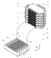
Fig. 1 has showed the oblique front lower place perspective exploded view of first embodiment of multi-core coaxial connector 1.Fig. 2 has showed identical multi-core connector 1 from oblique front upper place, and Fig. 3 has showed opening exploded view and partly dissecing exploded view of described multi-core connector from oblique upper.
Described multi-core coaxial connector 1 comprises public affairs, a female connectors group 2,3, by a connection procedure, described connector group can exercisable company towards each other.These two parts 2,3 have a plurality of public affairs and female connectors 4,5, are coaxial here, and described connector 4,5 is arranged in public integral type or the multiple-piece outer enclosure, and the top is that first shell, below are second shells.Public and female coaxial connector 4,5 amplifies explanation in Fig. 4 and Fig. 5.In these figure, public and female coaxial connector 4,5 divides other, and the state of connector group 2,3 exploded views is from separating (not having exercisable connection) to each other, so that detail can see more clearly.Be arranged in to guide pin 27 on the shell 6 of public connector end 2, in second shell 7, work as the exercisable company of described public connector end to female connectors end 3, and the shell of calibrating individual connector end 2,3 is when being in alignment with each other, described to guide pin agree with providing for it to heart hole 28 in.Show among this embodiment that connector group 2,3 has 16 connectors in each case, described connector does not form above the tolerance chain of 16 connectors so that have each other in to connecting.In order to make coaxial connector 4,5 in connection procedure, be in alignment with each other, substitute or replenish as a kind of, the horizontal direction that they can be mounted at least one side in one of shell 6,7 floats.
As shown in Figure 3, the outer enclosure 6 of the public connector group 2 of multi-core coaxial connector 1 is the multiple-piece design.It has a matrix 8, and described matrix 8 has the breach of arranging in the pectination mode 9 that is suitable for holding public connector 4.Described breach 9 is arranged on two opposite flanks of matrix 8, and about parallel each other.They are arranged to two rows, and with reference to elementary contour lateral offset each other, are 60 ° of angles at this, (other forms of layout also is possible).Because breach 9 is designed to all can enter from both sides, so matrix 8 can hold connector 4,5 with high-bulk-density easily.Breach 9 can be designed to this mode: make the horizontal fastener of connector 4 energy in described breach.
According to the field of using, described lid 10 can glued joint, is threaded, welds by snap action, and movable or permanent exercisable company is to matrix 8.Connector 4 can be arranged in the breach 9 with fixed form, perhaps in order to move to confining spectrum, certain tolerance is arranged at least in the horizontal.According to application, breach 9 also can be a U-shaped, so as single connector 4 from the side fastener in described breach and no longer need the lid.
Different with first case member 6, second case member 7 of illustrated embodiment is an integral design, and plan is installed in (unspecified) on the circuit board. described second case member 7 has a plurality of holes that are arranged in parallel 11, is used to hold connector 5.Female connectors 5 is pressed in the hole 11 for this reason.In described embodiment, under the situation that second case member 7 is designed to conduct electricity, form shielding.In case of necessity, second shell 7 can have the connector 5 more than two rows.
Shown in Fig. 3-5, public connector 4 is directly installed on the coaxial cable 12 separately.The frame mode of connector 4,5 is relevant with the bulk density that can reach.For this reason, guaranteed that high integration and a special compact structure are arranged in connector 4,5.
Tubular external component 13 is installed on the outer cover 16 of coaxial cable 12.According to application, can use various mounting meanss.By connecing, glued joint or welding and to realize good result.One first internal part 20 equally also is a tubular, is inserted on the inner conductor 19 of coaxial cable 12, and end toper enlarges also and has groove 21 before described first internal part, the scope that makes elastic force be no more than to define.In order to improve connection, described tubular internal part 20 has internal structure second reinforcement.Produced gap between tubular external component 13 and the inner conductor 19 by the insulating tool 23 of coaxial cable 12.In addition, in case of necessity, further spacer means for example is made up of plastics or other non-conducting materials, can provide between the external component in the public connector 4 13 and first internal part 20.
As shown in the Examples, female connectors 5 comprises a sleeve 24 and needle-like second internal part 25.Described second internal part 25 is pressed in the sleeve 24, and has anchoring element 26 and be used for stoping unexpected moving.Afterbody is the thickening design, and (with reference to Fig. 3) stretches out shell 7 in installment state, as the contactor (not having further diagram) to printed circuit board (PCB).
As seen from Figure 3, female connectors parts 5 are pressed into hole 11 shell 7 from afterbody, and are positioned at the inside of described second shell in installment state.As shown in the Examples, not shielding of female connectors parts.This is provided by second shell 7, and described shell 7 is all by the electric conducting material manufacturing, perhaps the regional coated with conductive material of 11 inner surface in the hole at least.Can be operatively connected state, the conduction that the conduction external component 13 of public connector 5 has formed to the inner surface of hole 11 (external conductor) connects.Simultaneously, tubular first internal part 20 and needle-like 25 similar exercisable connections of second internal part, and formed a spendable connection, be used to transmit radio-frequency signal (inner conductor).
Fig. 6 has showed the perspective exploded view of an a kind of embodiment of multi-core coaxial connector array 30.Connector 30 has the modular structure of a high quantity passage of per unit area.In the embodiment shown, public connector parts 31 comprise single connector end 2, and by the elastic bracket 32 of transverse arrangement of turbo, described connector end 2 is with the exercisable connection shoulder to shoulder parallel to each other of ralocatable mode.According to application, in case of necessity, described connector end 2 also can connect towards each other in a fixed manner.In case of necessity, coaxial connector 4,5 similarly is installed in the shell 6,7 in the laterally floating mode of confining spectrum.
As shown in the Examples, the shell of female connectors parts 33 comprises a plurality of single connector ends 3, shown in Fig. 1 to 3.Described connector end 3 is installed on the printed circuit board (PCB) each other shoulder to shoulder.
Fig. 7 has showed the oblique upper perspective exploded view of a kind of second embodiment of multi-core coaxial connector 1.This structure corresponds essentially to the connector 1 of Fig. 1 in Fig. 3.Therefore, for describing total operational mode, can illustrate with reference to these.For better understanding, first shell 6 exploded view under open mode, second shell 7 are that part is dissectd exploded view.
With respect to the connector of Fig. 1 in Fig. 3, connector shown here is row's design.The shell 6 of public connector group 2 is two-piece type designs, and comprises a matrix 8 with a plurality of breach 9, and described breach 9 arranges each other shoulder to shoulder, is used to hold cable 12 and the exercisable company public coaxial connector 4 to described cable.Described connector 4 has reinforcement 17, and under installment state, reinforcement 17 is arranged in the groove 18, stops moving on the longitudinal direction.The lid 10 that has the breach 9 of similar respective numbers is used to close shell 6 (shown in figure center line s).In the tail region of breach 9, matrix 8 and lid 10 have (are dimensioned) constriction 29 by the size customization, so that in off position down, cable 12 is clamped in this zone with controllable mode, be used for the purpose of strain relief.Female connectors end 3 is similar row's formula designs.In the embodiment shown, female connectors 5 similarly is pressed into from afterbody second shell 7.
Fig. 8 has showed two male and female connectors 4,5, and each all is arranged above and below.Connector is to 4,5 the preceding, and cut in anterior 90 ° of zones, so that the inside of connector 4,5 is more high-visible.This connector 4,5 still, also can use in the embodiment of aforementioned arbitrary accompanying drawing in principle corresponding to the connector 4,5 of the 3rd embodiment of the multi-core coaxial connector 1 among Fig. 7.
(with respect to the embodiment according to Fig. 4 and Fig. 5) in this case, female connectors 5 have 35, one second sleeves 36 of an external conductor to make the external conductor 35 and second internal part 25 separate.In the plug connection status, external conductor 35 contacts alternately with the tubular external component 13 of matching parts 4, and simultaneously, in the plug connection status, first internal part 20 connects second internal part 25 conductively.
In order to make the connection between each parts be based upon on a kind of reliable mode, and the certain geometrical deviation on the compensation vertical and horizontal, the external conductor and second internal part all have spring 37,38.With respect to the connector 4,5 that laterally contact alternately among Fig. 4 and Fig. 5, connector the 4, the 5th herein, end face contacts.
[primary clustering symbol description]
1 multi-core connector
2 public connector groups
3 female connectors groups
4 public connectors
5 female connectors
6 first shells
7 second housings
8 matrixes
9 breach
10 lids
11 holes
12 coaxial cables
13 tubular external components
14 grooves
15 shoulders
16 outer cover/shieldings
17 first reinforcements
18 grooves
19 inner conductors
20 first internal parts
21 grooves
22 second reinforcements
23 look edge instruments
24 sleeves
25 second internal parts
26 anchoring elements
27 to guide pin
28 pairs of heart holes
29 constriction
30 cut cable connector components
31 public connector parts
32 elastic brackets
33 female connectors parts
34 first sleeves
35 external conductors
36 second sleeves
37 first springs
38 second springs
Claims (11)
1. multi-core coaxial connector (1,30), have female connectors parts and cut cable public connector parts (2,31), described cut cable public connector parts (2,31) have a modular structure, described modular structure has a connector group (2) at least, described connector group (2) has the shell (6) of ribbon matrix (8), matrix (8) has breach (9), described breach (9) is enterable from one or two opposite flank, and is used for laterally holding the single connector (4,5) with support and connection device group (2).
2. multi-core coaxial connector as claimed in claim 1 (1) is characterized in that: described cut cable public connector parts (31) have a plurality of connector groups (2), the laterally exercisable shoulder to shoulder each other connection of these connector groups (2).
3. multi-core coaxial connector as claimed in claim 2 (1) is characterized in that: described cut cable connector group (2) is arranged as and can moves relative to each other.
4. multi-core coaxial connector as claimed in claim 3 (1) is characterized in that: described cut cable connector group (2) is connected to each other so that ralocatable mode is exercisable by elastic coupling element (32).
5. multi-core coaxial connector as claimed in claim 2 (1) is characterized in that: described cut cable connector group (2) is connected to each other so that rigid manner is exercisable.
6. arbitrary as described above described multi-core coaxial connector of claim (1) is characterized in that: a described connector group (2) has a row or two row's connectors (4,5).
7. arbitrary as described above described multi-core coaxial connector of claim (1), it is characterized in that: described female connectors parts (3,33) have an integral type shell (7), described shell (7) has the breach (9) that is arranged in parallel, and is used to hold single connector (5).
8. multi-core coaxial connector as claimed in claim 7 (1) is characterized in that: described connector (5) is pressed into from afterbody.
9. as claim 7 or 8 described multi-core coaxial connectors (1), it is characterized in that: described integral type shell (7) has multirow breach (9).
10. arbitrary as described above described multi-core coaxial connector of claim (1) is characterized in that: single connector (4,5) at least in a shell (6,7) install in the laterally floating mode.
11. the described multi-core coaxial connector of arbitrary as described above claim (1) is characterized in that: connector group (2,3) has heart instrument, by to heart instrument, described shell (6,7) in the plug connection procedure about each other to the heart.
Applications Claiming Priority (3)
| Application Number | Priority Date | Filing Date | Title |
|---|---|---|---|
| CH5442008 | 2008-04-08 | ||
| CH00544/08 | 2008-04-08 | ||
| PCT/EP2009/051602 WO2009124797A1 (en) | 2008-04-08 | 2009-02-11 | Multiple coaxial connector |
Publications (1)
| Publication Number | Publication Date |
|---|---|
| CN101983459A true CN101983459A (en) | 2011-03-02 |
Family
ID=40823224
Family Applications (1)
| Application Number | Title | Priority Date | Filing Date |
|---|---|---|---|
| CN2009801120493A Pending CN101983459A (en) | 2008-04-08 | 2009-02-11 | Multiple coaxial connector |
Country Status (7)
| Country | Link |
|---|---|
| US (1) | US8360805B2 (en) |
| EP (1) | EP2260543B1 (en) |
| JP (1) | JP5459724B2 (en) |
| CN (1) | CN101983459A (en) |
| AT (1) | ATE542269T1 (en) |
| IL (1) | IL207983A (en) |
| WO (1) | WO2009124797A1 (en) |
Cited By (5)
| Publication number | Priority date | Publication date | Assignee | Title |
|---|---|---|---|---|
| CN103884879A (en) * | 2012-12-21 | 2014-06-25 | 北京普源精电科技有限公司 | Multichannel signal obtaining probe and use method thereof |
| CN107221820A (en) * | 2017-06-29 | 2017-09-29 | 深圳市深台帏翔电子有限公司 | terminal device and its integrated connector |
| CN109004403A (en) * | 2017-06-07 | 2018-12-14 | 中国探针股份有限公司 | High-frequency electronic connector |
| CN109411943A (en) * | 2017-08-17 | 2019-03-01 | 富士康(昆山)电脑接插件有限公司 | Pin connector mould group |
| CN110829127A (en) * | 2018-08-07 | 2020-02-21 | Smk株式会社 | Coaxial connector |
Families Citing this family (15)
| Publication number | Priority date | Publication date | Assignee | Title |
|---|---|---|---|---|
| US8002574B1 (en) * | 2010-11-04 | 2011-08-23 | Tyco Electronics Corporation | RF module with a housing with spring loaded connectors and a strain relief extending rearward of the housing |
| US8550859B2 (en) | 2011-10-20 | 2013-10-08 | Andrew Llc | Close proximity panel mount connectors |
| US8935849B2 (en) * | 2011-03-10 | 2015-01-20 | Fci Americas Technology Llc | Method for mounting a cable connector onto a panel |
| US8923776B1 (en) * | 2011-05-17 | 2014-12-30 | Bae Systems Information And Electronic Systems Integration Inc. | Short loop connection method |
| KR101343814B1 (en) | 2012-10-16 | 2013-12-20 | 한국광성전자 주식회사 | Multimedia devices for vehicle intergrated antena and tuner module |
| DE102012110907B4 (en) | 2012-11-13 | 2019-06-13 | Harting Electric Gmbh & Co. Kg | Holding frame for holding connector modules |
| KR101575441B1 (en) * | 2013-12-30 | 2015-12-07 | 현대자동차주식회사 | RF connector assembly for vehicle |
| JP6452565B2 (en) * | 2015-07-15 | 2019-01-16 | 日本航空電子工業株式会社 | Cable connection structure, cable alignment parts |
| CN115241696A (en) | 2016-05-31 | 2022-10-25 | 安费诺有限公司 | High-performance cable termination device |
| US10044155B1 (en) | 2017-05-10 | 2018-08-07 | Qualcomm Incorporated | Connector for connecting a device to a plurality of pads arranged at different radial distances from the source |
| TWI790268B (en) | 2017-08-03 | 2023-01-21 | 美商安芬諾股份有限公司 | Connector for low loss interconnection system and electronic system comprising the same |
| DE102017124594A1 (en) * | 2017-10-20 | 2019-04-25 | Harting Electric Gmbh & Co. Kg | Device for electrical contacting |
| CN113728521A (en) | 2019-02-22 | 2021-11-30 | 安费诺有限公司 | High performance cable connector assembly |
| FR3112246B1 (en) * | 2020-07-03 | 2023-03-31 | Radiall Sa | Ground contact comprising an axisymmetric bellows extended by retaining walls, Unitary coaxial RF connector integrating such a ground contact, for a board-to-board connection. |
| US11502440B2 (en) * | 2020-10-23 | 2022-11-15 | Carlisle Interconnect Technologies, Inc. | Multiport connector interface system |
Citations (4)
| Publication number | Priority date | Publication date | Assignee | Title |
|---|---|---|---|---|
| US5190472A (en) * | 1992-03-24 | 1993-03-02 | W. L. Gore & Associates, Inc. | Miniaturized high-density coaxial connector system with staggered grouper modules |
| WO1998033237A1 (en) * | 1997-01-24 | 1998-07-30 | Nokia Telecommunications Oy | Housing for coaxial connectors |
| US6524135B1 (en) * | 1999-09-20 | 2003-02-25 | 3M Innovative Properties Company | Controlled impedance cable connector |
| US20030203677A1 (en) * | 2000-05-05 | 2003-10-30 | Marko Spiegel | Modular shielded connector |
Family Cites Families (9)
| Publication number | Priority date | Publication date | Assignee | Title |
|---|---|---|---|---|
| JPS5341795B2 (en) * | 1972-08-31 | 1978-11-07 | ||
| US4571014A (en) * | 1984-05-02 | 1986-02-18 | At&T Bell Laboratories | High frequency modular connector |
| US4767345A (en) * | 1987-03-27 | 1988-08-30 | Amp Incorporated | High-density, modular, electrical connector |
| US5194020A (en) * | 1991-06-17 | 1993-03-16 | W. L. Gore & Associates, Inc. | High-density coaxial interconnect system |
| DE9210810U1 (en) | 1992-08-12 | 1992-10-15 | Siemens Ag, 8000 Muenchen, De | |
| JPH1092506A (en) * | 1996-09-11 | 1998-04-10 | Harness Sogo Gijutsu Kenkyusho:Kk | Connector for multi-conductor cable |
| DE59704625D1 (en) | 1997-01-28 | 2001-10-18 | Tyco Electronics Logistics Ag | RF COAXIAL CONNECTOR |
| US6824427B1 (en) * | 2003-05-13 | 2004-11-30 | 3M Innovative Properties Company | Coaxial probe interconnection system |
| US7404718B2 (en) * | 2003-11-05 | 2008-07-29 | Tensolite Company | High frequency connector assembly |
-
2009
- 2009-02-11 WO PCT/EP2009/051602 patent/WO2009124797A1/en active Application Filing
- 2009-02-11 EP EP09730580A patent/EP2260543B1/en active Active
- 2009-02-11 JP JP2011503390A patent/JP5459724B2/en active Active
- 2009-02-11 AT AT09730580T patent/ATE542269T1/en active
- 2009-02-11 US US12/936,553 patent/US8360805B2/en active Active
- 2009-02-11 CN CN2009801120493A patent/CN101983459A/en active Pending
-
2010
- 2010-09-05 IL IL207983A patent/IL207983A/en active IP Right Grant
Patent Citations (4)
| Publication number | Priority date | Publication date | Assignee | Title |
|---|---|---|---|---|
| US5190472A (en) * | 1992-03-24 | 1993-03-02 | W. L. Gore & Associates, Inc. | Miniaturized high-density coaxial connector system with staggered grouper modules |
| WO1998033237A1 (en) * | 1997-01-24 | 1998-07-30 | Nokia Telecommunications Oy | Housing for coaxial connectors |
| US6524135B1 (en) * | 1999-09-20 | 2003-02-25 | 3M Innovative Properties Company | Controlled impedance cable connector |
| US20030203677A1 (en) * | 2000-05-05 | 2003-10-30 | Marko Spiegel | Modular shielded connector |
Cited By (7)
| Publication number | Priority date | Publication date | Assignee | Title |
|---|---|---|---|---|
| CN103884879A (en) * | 2012-12-21 | 2014-06-25 | 北京普源精电科技有限公司 | Multichannel signal obtaining probe and use method thereof |
| CN103884879B (en) * | 2012-12-21 | 2017-10-24 | 北京普源精电科技有限公司 | A kind of multi-channel signal acquisition probe and its application method |
| CN109004403A (en) * | 2017-06-07 | 2018-12-14 | 中国探针股份有限公司 | High-frequency electronic connector |
| CN107221820A (en) * | 2017-06-29 | 2017-09-29 | 深圳市深台帏翔电子有限公司 | terminal device and its integrated connector |
| CN107221820B (en) * | 2017-06-29 | 2024-02-27 | 深圳市深台帏翔电子有限公司 | Terminal equipment and integrated connector thereof |
| CN109411943A (en) * | 2017-08-17 | 2019-03-01 | 富士康(昆山)电脑接插件有限公司 | Pin connector mould group |
| CN110829127A (en) * | 2018-08-07 | 2020-02-21 | Smk株式会社 | Coaxial connector |
Also Published As
| Publication number | Publication date |
|---|---|
| IL207983A (en) | 2013-03-24 |
| IL207983A0 (en) | 2010-12-30 |
| ATE542269T1 (en) | 2012-02-15 |
| JP2011517038A (en) | 2011-05-26 |
| US8360805B2 (en) | 2013-01-29 |
| EP2260543B1 (en) | 2012-01-18 |
| EP2260543A1 (en) | 2010-12-15 |
| WO2009124797A1 (en) | 2009-10-15 |
| JP5459724B2 (en) | 2014-04-02 |
| US20110237122A1 (en) | 2011-09-29 |
Similar Documents
| Publication | Publication Date | Title |
|---|---|---|
| CN101983459A (en) | Multiple coaxial connector | |
| US11011874B2 (en) | Connector and connector assembly | |
| US9985389B1 (en) | Connector assembly having a pin organizer | |
| TWI569537B (en) | Grounding structures for header and receptacle assemblies | |
| US10186811B1 (en) | Shielding for connector assembly | |
| CN103384042B (en) | Jack assemblies for midplane connector system | |
| TWI763704B (en) | An electrical connector assembly and a method of mounting an electrical connector assembly to a substrate | |
| TWI569516B (en) | Midplane orthogonal connector system | |
| CN106067610B (en) | Electric connector with grounded bracket | |
| CN109728456B (en) | Connector assembly with conductive gasket | |
| US7651342B1 (en) | Dual-interface electrical connector with anti-crosstalk means therebetween | |
| EP2250707B1 (en) | High-speed backplane connector | |
| US6910897B2 (en) | Interconnection system | |
| CN104348015B (en) | For the spacer element of cable back board system | |
| CN105659441B (en) | The connector directly adhered to | |
| JP2011527819A (en) | Carrier assembly and system configured to common ground headers | |
| CN104244661A (en) | Spacers for a cable backplane system | |
| TWI758401B (en) | Electrical connector having a mating connector interface | |
| CN104244655B (en) | Cable back board system | |
| CN105098515B (en) | Sandwich-type pin connector | |
| CN101437361A (en) | Printed circuit board assembly | |
| CN102185196B (en) | Electrical connector system | |
| CN102570116A (en) | Interface contact for an electrical connector | |
| EP0939456A2 (en) | Modular box shield for forming a coaxial header | |
| US8202117B2 (en) | Electrical connector having reduced number of shields |
Legal Events
| Date | Code | Title | Description |
|---|---|---|---|
| C06 | Publication | ||
| PB01 | Publication | ||
| C10 | Entry into substantive examination | ||
| SE01 | Entry into force of request for substantive examination | ||
| C12 | Rejection of a patent application after its publication | ||
| RJ01 | Rejection of invention patent application after publication |
Application publication date: 20110302 |