CN102640012A - Ultrasound 3D imaging system - Google Patents
Ultrasound 3D imaging system Download PDFInfo
- Publication number
- CN102640012A CN102640012A CN2010800541394A CN201080054139A CN102640012A CN 102640012 A CN102640012 A CN 102640012A CN 2010800541394 A CN2010800541394 A CN 2010800541394A CN 201080054139 A CN201080054139 A CN 201080054139A CN 102640012 A CN102640012 A CN 102640012A
- Authority
- CN
- China
- Prior art keywords
- array
- numerous
- forms
- circuit
- subarray
- Prior art date
- Legal status (The legal status is an assumption and is not a legal conclusion. Google has not performed a legal analysis and makes no representation as to the accuracy of the status listed.)
- Pending
Links
Images


Classifications
-
- A—HUMAN NECESSITIES
- A61—MEDICAL OR VETERINARY SCIENCE; HYGIENE
- A61B—DIAGNOSIS; SURGERY; IDENTIFICATION
- A61B8/00—Diagnosis using ultrasonic, sonic or infrasonic waves
- A61B8/13—Tomography
- A61B8/14—Echo-tomography
-
- A—HUMAN NECESSITIES
- A61—MEDICAL OR VETERINARY SCIENCE; HYGIENE
- A61B—DIAGNOSIS; SURGERY; IDENTIFICATION
- A61B8/00—Diagnosis using ultrasonic, sonic or infrasonic waves
- A61B8/13—Tomography
- A61B8/14—Echo-tomography
- A61B8/145—Echo-tomography characterised by scanning multiple planes
-
- A—HUMAN NECESSITIES
- A61—MEDICAL OR VETERINARY SCIENCE; HYGIENE
- A61B—DIAGNOSIS; SURGERY; IDENTIFICATION
- A61B8/00—Diagnosis using ultrasonic, sonic or infrasonic waves
- A61B8/44—Constructional features of the ultrasonic, sonic or infrasonic diagnostic device
- A61B8/4444—Constructional features of the ultrasonic, sonic or infrasonic diagnostic device related to the probe
-
- A—HUMAN NECESSITIES
- A61—MEDICAL OR VETERINARY SCIENCE; HYGIENE
- A61B—DIAGNOSIS; SURGERY; IDENTIFICATION
- A61B8/00—Diagnosis using ultrasonic, sonic or infrasonic waves
- A61B8/44—Constructional features of the ultrasonic, sonic or infrasonic diagnostic device
- A61B8/4483—Constructional features of the ultrasonic, sonic or infrasonic diagnostic device characterised by features of the ultrasound transducer
- A61B8/4488—Constructional features of the ultrasonic, sonic or infrasonic diagnostic device characterised by features of the ultrasound transducer the transducer being a phased array
-
- A—HUMAN NECESSITIES
- A61—MEDICAL OR VETERINARY SCIENCE; HYGIENE
- A61B—DIAGNOSIS; SURGERY; IDENTIFICATION
- A61B8/00—Diagnosis using ultrasonic, sonic or infrasonic waves
- A61B8/46—Ultrasonic, sonic or infrasonic diagnostic devices with special arrangements for interfacing with the operator or the patient
- A61B8/461—Displaying means of special interest
- A61B8/466—Displaying means of special interest adapted to display 3D data
-
- A—HUMAN NECESSITIES
- A61—MEDICAL OR VETERINARY SCIENCE; HYGIENE
- A61B—DIAGNOSIS; SURGERY; IDENTIFICATION
- A61B8/00—Diagnosis using ultrasonic, sonic or infrasonic waves
- A61B8/48—Diagnostic techniques
- A61B8/483—Diagnostic techniques involving the acquisition of a 3D volume of data
-
- A—HUMAN NECESSITIES
- A61—MEDICAL OR VETERINARY SCIENCE; HYGIENE
- A61B—DIAGNOSIS; SURGERY; IDENTIFICATION
- A61B8/00—Diagnosis using ultrasonic, sonic or infrasonic waves
- A61B8/48—Diagnostic techniques
- A61B8/488—Diagnostic techniques involving Doppler signals
-
- A—HUMAN NECESSITIES
- A61—MEDICAL OR VETERINARY SCIENCE; HYGIENE
- A61B—DIAGNOSIS; SURGERY; IDENTIFICATION
- A61B8/00—Diagnosis using ultrasonic, sonic or infrasonic waves
- A61B8/52—Devices using data or image processing specially adapted for diagnosis using ultrasonic, sonic or infrasonic waves
-
- A—HUMAN NECESSITIES
- A61—MEDICAL OR VETERINARY SCIENCE; HYGIENE
- A61B—DIAGNOSIS; SURGERY; IDENTIFICATION
- A61B8/00—Diagnosis using ultrasonic, sonic or infrasonic waves
- A61B8/54—Control of the diagnostic device
-
- G—PHYSICS
- G01—MEASURING; TESTING
- G01S—RADIO DIRECTION-FINDING; RADIO NAVIGATION; DETERMINING DISTANCE OR VELOCITY BY USE OF RADIO WAVES; LOCATING OR PRESENCE-DETECTING BY USE OF THE REFLECTION OR RERADIATION OF RADIO WAVES; ANALOGOUS ARRANGEMENTS USING OTHER WAVES
- G01S15/00—Systems using the reflection or reradiation of acoustic waves, e.g. sonar systems
- G01S15/88—Sonar systems specially adapted for specific applications
- G01S15/89—Sonar systems specially adapted for specific applications for mapping or imaging
- G01S15/8906—Short-range imaging systems; Acoustic microscope systems using pulse-echo techniques
- G01S15/8909—Short-range imaging systems; Acoustic microscope systems using pulse-echo techniques using a static transducer configuration
- G01S15/8915—Short-range imaging systems; Acoustic microscope systems using pulse-echo techniques using a static transducer configuration using a transducer array
- G01S15/8925—Short-range imaging systems; Acoustic microscope systems using pulse-echo techniques using a static transducer configuration using a transducer array the array being a two-dimensional transducer configuration, i.e. matrix or orthogonal linear arrays
-
- G—PHYSICS
- G01—MEASURING; TESTING
- G01S—RADIO DIRECTION-FINDING; RADIO NAVIGATION; DETERMINING DISTANCE OR VELOCITY BY USE OF RADIO WAVES; LOCATING OR PRESENCE-DETECTING BY USE OF THE REFLECTION OR RERADIATION OF RADIO WAVES; ANALOGOUS ARRANGEMENTS USING OTHER WAVES
- G01S15/00—Systems using the reflection or reradiation of acoustic waves, e.g. sonar systems
- G01S15/88—Sonar systems specially adapted for specific applications
- G01S15/89—Sonar systems specially adapted for specific applications for mapping or imaging
- G01S15/8906—Short-range imaging systems; Acoustic microscope systems using pulse-echo techniques
- G01S15/8909—Short-range imaging systems; Acoustic microscope systems using pulse-echo techniques using a static transducer configuration
- G01S15/8915—Short-range imaging systems; Acoustic microscope systems using pulse-echo techniques using a static transducer configuration using a transducer array
- G01S15/8927—Short-range imaging systems; Acoustic microscope systems using pulse-echo techniques using a static transducer configuration using a transducer array using simultaneously or sequentially two or more subarrays or subapertures
-
- G—PHYSICS
- G01—MEASURING; TESTING
- G01S—RADIO DIRECTION-FINDING; RADIO NAVIGATION; DETERMINING DISTANCE OR VELOCITY BY USE OF RADIO WAVES; LOCATING OR PRESENCE-DETECTING BY USE OF THE REFLECTION OR RERADIATION OF RADIO WAVES; ANALOGOUS ARRANGEMENTS USING OTHER WAVES
- G01S15/00—Systems using the reflection or reradiation of acoustic waves, e.g. sonar systems
- G01S15/88—Sonar systems specially adapted for specific applications
- G01S15/89—Sonar systems specially adapted for specific applications for mapping or imaging
- G01S15/8906—Short-range imaging systems; Acoustic microscope systems using pulse-echo techniques
- G01S15/8959—Short-range imaging systems; Acoustic microscope systems using pulse-echo techniques using coded signals for correlation purposes
- G01S15/8961—Short-range imaging systems; Acoustic microscope systems using pulse-echo techniques using coded signals for correlation purposes using pulse compression
-
- G—PHYSICS
- G01—MEASURING; TESTING
- G01S—RADIO DIRECTION-FINDING; RADIO NAVIGATION; DETERMINING DISTANCE OR VELOCITY BY USE OF RADIO WAVES; LOCATING OR PRESENCE-DETECTING BY USE OF THE REFLECTION OR RERADIATION OF RADIO WAVES; ANALOGOUS ARRANGEMENTS USING OTHER WAVES
- G01S7/00—Details of systems according to groups G01S13/00, G01S15/00, G01S17/00
- G01S7/52—Details of systems according to groups G01S13/00, G01S15/00, G01S17/00 of systems according to group G01S15/00
- G01S7/52017—Details of systems according to groups G01S13/00, G01S15/00, G01S17/00 of systems according to group G01S15/00 particularly adapted to short-range imaging
- G01S7/52079—Constructional features
- G01S7/5208—Constructional features with integration of processing functions inside probe or scanhead
-
- G—PHYSICS
- G01—MEASURING; TESTING
- G01S—RADIO DIRECTION-FINDING; RADIO NAVIGATION; DETERMINING DISTANCE OR VELOCITY BY USE OF RADIO WAVES; LOCATING OR PRESENCE-DETECTING BY USE OF THE REFLECTION OR RERADIATION OF RADIO WAVES; ANALOGOUS ARRANGEMENTS USING OTHER WAVES
- G01S7/00—Details of systems according to groups G01S13/00, G01S15/00, G01S17/00
- G01S7/52—Details of systems according to groups G01S13/00, G01S15/00, G01S17/00 of systems according to group G01S15/00
- G01S7/52017—Details of systems according to groups G01S13/00, G01S15/00, G01S17/00 of systems according to group G01S15/00 particularly adapted to short-range imaging
- G01S7/52079—Constructional features
- G01S7/52082—Constructional features involving a modular construction, e.g. a computer with short range imaging equipment
-
- G—PHYSICS
- G01—MEASURING; TESTING
- G01S—RADIO DIRECTION-FINDING; RADIO NAVIGATION; DETERMINING DISTANCE OR VELOCITY BY USE OF RADIO WAVES; LOCATING OR PRESENCE-DETECTING BY USE OF THE REFLECTION OR RERADIATION OF RADIO WAVES; ANALOGOUS ARRANGEMENTS USING OTHER WAVES
- G01S7/00—Details of systems according to groups G01S13/00, G01S15/00, G01S17/00
- G01S7/52—Details of systems according to groups G01S13/00, G01S15/00, G01S17/00 of systems according to group G01S15/00
- G01S7/52017—Details of systems according to groups G01S13/00, G01S15/00, G01S17/00 of systems according to group G01S15/00 particularly adapted to short-range imaging
- G01S7/52085—Details related to the ultrasound signal acquisition, e.g. scan sequences
- G01S7/52095—Details related to the ultrasound signal acquisition, e.g. scan sequences using multiline receive beamforming
-
- G—PHYSICS
- G10—MUSICAL INSTRUMENTS; ACOUSTICS
- G10K—SOUND-PRODUCING DEVICES; METHODS OR DEVICES FOR PROTECTING AGAINST, OR FOR DAMPING, NOISE OR OTHER ACOUSTIC WAVES IN GENERAL; ACOUSTICS NOT OTHERWISE PROVIDED FOR
- G10K11/00—Methods or devices for transmitting, conducting or directing sound in general; Methods or devices for protecting against, or for damping, noise or other acoustic waves in general
- G10K11/18—Methods or devices for transmitting, conducting or directing sound
- G10K11/26—Sound-focusing or directing, e.g. scanning
- G10K11/34—Sound-focusing or directing, e.g. scanning using electrical steering of transducer arrays, e.g. beam steering
- G10K11/341—Circuits therefor
- G10K11/346—Circuits therefor using phase variation
-
- A—HUMAN NECESSITIES
- A61—MEDICAL OR VETERINARY SCIENCE; HYGIENE
- A61B—DIAGNOSIS; SURGERY; IDENTIFICATION
- A61B8/00—Diagnosis using ultrasonic, sonic or infrasonic waves
- A61B8/08—Detecting organic movements or changes, e.g. tumours, cysts, swellings
-
- A—HUMAN NECESSITIES
- A61—MEDICAL OR VETERINARY SCIENCE; HYGIENE
- A61B—DIAGNOSIS; SURGERY; IDENTIFICATION
- A61B8/00—Diagnosis using ultrasonic, sonic or infrasonic waves
- A61B8/08—Detecting organic movements or changes, e.g. tumours, cysts, swellings
- A61B8/0883—Detecting organic movements or changes, e.g. tumours, cysts, swellings for diagnosis of the heart
-
- A—HUMAN NECESSITIES
- A61—MEDICAL OR VETERINARY SCIENCE; HYGIENE
- A61B—DIAGNOSIS; SURGERY; IDENTIFICATION
- A61B8/00—Diagnosis using ultrasonic, sonic or infrasonic waves
- A61B8/44—Constructional features of the ultrasonic, sonic or infrasonic diagnostic device
- A61B8/4411—Device being modular
-
- A—HUMAN NECESSITIES
- A61—MEDICAL OR VETERINARY SCIENCE; HYGIENE
- A61B—DIAGNOSIS; SURGERY; IDENTIFICATION
- A61B8/00—Diagnosis using ultrasonic, sonic or infrasonic waves
- A61B8/44—Constructional features of the ultrasonic, sonic or infrasonic diagnostic device
- A61B8/4444—Constructional features of the ultrasonic, sonic or infrasonic diagnostic device related to the probe
- A61B8/4472—Wireless probes
-
- A—HUMAN NECESSITIES
- A61—MEDICAL OR VETERINARY SCIENCE; HYGIENE
- A61B—DIAGNOSIS; SURGERY; IDENTIFICATION
- A61B8/00—Diagnosis using ultrasonic, sonic or infrasonic waves
- A61B8/54—Control of the diagnostic device
- A61B8/543—Control of the diagnostic device involving acquisition triggered by a physiological signal
-
- A—HUMAN NECESSITIES
- A61—MEDICAL OR VETERINARY SCIENCE; HYGIENE
- A61B—DIAGNOSIS; SURGERY; IDENTIFICATION
- A61B8/00—Diagnosis using ultrasonic, sonic or infrasonic waves
- A61B8/56—Details of data transmission or power supply
- A61B8/565—Details of data transmission or power supply involving data transmission via a network
-
- G—PHYSICS
- G01—MEASURING; TESTING
- G01S—RADIO DIRECTION-FINDING; RADIO NAVIGATION; DETERMINING DISTANCE OR VELOCITY BY USE OF RADIO WAVES; LOCATING OR PRESENCE-DETECTING BY USE OF THE REFLECTION OR RERADIATION OF RADIO WAVES; ANALOGOUS ARRANGEMENTS USING OTHER WAVES
- G01S15/00—Systems using the reflection or reradiation of acoustic waves, e.g. sonar systems
- G01S15/88—Sonar systems specially adapted for specific applications
- G01S15/89—Sonar systems specially adapted for specific applications for mapping or imaging
- G01S15/8906—Short-range imaging systems; Acoustic microscope systems using pulse-echo techniques
- G01S15/8909—Short-range imaging systems; Acoustic microscope systems using pulse-echo techniques using a static transducer configuration
- G01S15/8913—Short-range imaging systems; Acoustic microscope systems using pulse-echo techniques using a static transducer configuration using separate transducers for transmission and reception
-
- G—PHYSICS
- G01—MEASURING; TESTING
- G01S—RADIO DIRECTION-FINDING; RADIO NAVIGATION; DETERMINING DISTANCE OR VELOCITY BY USE OF RADIO WAVES; LOCATING OR PRESENCE-DETECTING BY USE OF THE REFLECTION OR RERADIATION OF RADIO WAVES; ANALOGOUS ARRANGEMENTS USING OTHER WAVES
- G01S15/00—Systems using the reflection or reradiation of acoustic waves, e.g. sonar systems
- G01S15/88—Sonar systems specially adapted for specific applications
- G01S15/89—Sonar systems specially adapted for specific applications for mapping or imaging
- G01S15/8906—Short-range imaging systems; Acoustic microscope systems using pulse-echo techniques
- G01S15/8959—Short-range imaging systems; Acoustic microscope systems using pulse-echo techniques using coded signals for correlation purposes
-
- G—PHYSICS
- G01—MEASURING; TESTING
- G01S—RADIO DIRECTION-FINDING; RADIO NAVIGATION; DETERMINING DISTANCE OR VELOCITY BY USE OF RADIO WAVES; LOCATING OR PRESENCE-DETECTING BY USE OF THE REFLECTION OR RERADIATION OF RADIO WAVES; ANALOGOUS ARRANGEMENTS USING OTHER WAVES
- G01S15/00—Systems using the reflection or reradiation of acoustic waves, e.g. sonar systems
- G01S15/88—Sonar systems specially adapted for specific applications
- G01S15/89—Sonar systems specially adapted for specific applications for mapping or imaging
- G01S15/8906—Short-range imaging systems; Acoustic microscope systems using pulse-echo techniques
- G01S15/8993—Three dimensional imaging systems
Abstract
The present invention relates to an ultrasound imaging system in which the scan head includes a beamformer circuit that performs far field subarray beamforming or includes a sparse array selecting circuit that actuates selected elements. When using a hierarchical two- stage or three- stage beamforming system, three dimensional ultrasound images can be generated in real - time. The invention further relates to flexible printed circuit boards in the probe head. The invention furthermore relates to the use of coded or spread spectrum signalling in ultrasound imaging systems. Matched filters based on pulse compression using Golay code pairs improve the signal-to-noise ratio thus enabling third harmonic imaging with suppressed sidelobes. The system is suitable for 3D full volume cardiac imaging.
Description
Reference to related application
The application is the 12/570th of submission on September 30th, 2009; The part continuation application of No. 856 U.S. Patent applications; The 12/570th, No. 856 application is the part continuation application of the PCT/US09/56995 international patent application of submission on September 15th, 2009, and the PCT/US09/56995 international patent application is the 12/286th of submission on September 30th, 2008; The part continuation application of No. 555 U.S. Patent applications; And require to enjoy the denomination of invention of submitting on September 15th, 2008 by people such as Chiang and be " Ultrasound 3D Imaging System ", the right of priority of the 61/192nd, No. 063 U.S. Patent application.The same right of priority that requires to enjoy in the 11/474th, No. 098 U.S. Patent application of submitting on June 23rd, 2006 and the PCT/US2007/014526 international patent application of submitting on June 22nd, 2007 of the application.The full content of above patented claim is incorporated this paper at this into through quoting as proof.
Background technology
The medical ultrasound imaging technique has become a kind of industrial specification for most medical imaging is used.These technology have developed into three-dimensional (3D) image that is used to provide the internal, and use two dimension (2D) sensor array to handle.These system requirements use thousands of beams to form passage.What the power requirement that is used to make these systems carry out work used is to have the phase shift analogue technique that digital time-delay beam forms device, and this situation causes damage to picture quality.
Therefore, exist the demand that continues that the ultrasound imaging techniques that can improve real-time three-dimensional imaging ability is further improved.In addition, the ability of this raising will be supported the continuous real-time demonstration to four-dimensional functional.
Summary of the invention
What the application related to is a kind of system that is used for the medical ultrasonics imaging, and this system provides three-dimensional (3D) imaging through two dimension (2D) array that is positioned at the sensor element within the probe body.Various embodiment of the present invention provides the system and method for the medical imaging that is used to have high resolving power and multiple imaging form.
In preferred embodiments, probe body comprises first beam and forms circuit, and it sends to beam-forming data in second shell, and second shell has second beam and forms circuit.First beam forms circuit provides the subarray beam in far field to form operation.The beam-forming data from scan hair that is obtained is delivered in second shell, and second shell has the second beam-forming circuit, and its provider is to controlled and near field that can focus on.
A kind of embodiment preferred provides a kind of scanner head, and it can be connected in traditional ultrasonic system, wherein scans the processing capacity process that input is offered traditional formation beam.The beam of scanner head forms device can utilize lower powered electron region processor, and this processor has at least 32 beams and forms passage.
What a kind of preferred embodiment among the present invention adopted is thinned array, in this array, only needs the sub-fraction in the activated sensors element.Through four jiaos of selection of components in the array suitable average lobe bandwidth is provided, makes average side-lobe energy and clutter minimize, eliminate periodicity and make the ratio of peak value and secondary lobe maximize, thereby form the image that meets quality requirements.In order to control the direction of the beam that intersects with the volume of load and zone, the different sensor element must activate with suitable order, to keep the ratio between peak value and the secondary lobe.System processor can be provided for the desirable order of activated sensors through programming, so as can be on different angles beams directed.What can select is that the controller of discrete type can be used for the activation action of thinned array is controlled.A kind of embodiment preferred provides a kind of scanner head of integrated on-off circuit, and the formed beam that links to each other for order is then selected sparse array active element.Scanner head can be connected in traditional ultrasonic system, and scanner head is provided to input in traditional beam-forming processing capacity therein.In another embodiment, the element of emission array and the element of receiving array can be independent of the radiated element and the almost whole receiving elements of arranging full array of conduct that include thinned array to be operated.In a preferred embodiment, Port Multiplier and beam form the device circuit and can be integrated in the interface system, and what perhaps can select is to be integrated in the host process system, thereby will the reservation of 2D sensor array to be installed in the probe body.
Utilization of the present invention be to form the nondestructive induction in each stage of the time-delay element in the device at beam.Therefore, as far as with the delay line in 65 stages, for instance, 64 operable outputs in corresponding each stage.Temporal resolution can be at 1/8 λ within the scope of 1/16 λ.
In detector and nondestructive induction, use the high pressure Port Multiplier to allow to realize the formation of the multiplex order beam of time-devision system.Now feasible is that the exchange tap of selecting each bar delay line in order is to form the multichannel beam.
Except the ability that three-dimensional (3D) shows, four-dimensional or Time Domain Decomposition image show also can be used for, for example write down the order with display image with per second 10 frames or higher frequency.So just can browse quick changed features with the frame frequency speed of 30 frame/seconds, for example blood flow or body fluid flow; Heart wall moves or the like.
Another one embodiment preferred of the present invention utilization be that the beam with three phases forms the device system; Wherein the phase one comes from reception on the basis of data of sensor array and forms first beam shaping operation; It produces the first beam-forming data; It is followed by subordinate phase; Subordinate phase is carried out the operation of the second formation beam so that the beam shaping data of subordinate phase to be provided, and afterwards data is sent to three beam and forms the stage, and the three beam formation stage is carried out the operation that three beam forms.
Each stage can use the electron region processor to carry out.Before phase one or subordinate phase, the phase III or after stage before, data also can convert digital form into from analog form.A stage can be utilized parallel beam-forming operation, and subordinate phase provides the beam of sequence to form.
What preferred embodiment among the present invention was carried out is jumbo real time imagery, for example, and human heart, and need not to accomplish gate image and the process that these images are linked together of the different piece of heart according to order.This accomplishes through using beam-forming constructing, and wherein the multichannel beam can be launched with single pulse.This can be used for being collected in the adult cardiac image of single cardiac cycle or heartbeat.This beam formation system that also can form system and/or time domain through the beam of arrowband phase shift accomplishes.Being distributed in sensor surveys shell and the series-parallel beam in the shipping installation system of system's primary processor of shell and lightweight, portable and forms partly and can be used for real-time omnibearing cardiac imaging.
In the medical ultrasound technical field of imaging, need a kind of harmonic imaging technology, wherein the waveform of emission has a base frequency F
o, and the signal of the load that receives is higher harmonic wave, normally second harmonic (2F
o), or third harmonic (3F
o).The harmonic signal of load is to be produced by the imaging target area in health, and the harmonic wave in the waveform of emission does not have load.Therefore, importantly suppress the harmonic wave part in the waveform that comes from emission, so that obtain response comparatively clearly.
Radiating circuit both can produce square wave also can produce sinusoidal wave excitation.Generally, square-wave pulse generator is more cheap than sine pulse generator, and square-wave pulse generator has application more widely in supersonic imaging device.Yet a kind of typical square wave self also contains the noble potential of third harmonic.What the present invention used is the square wave through revising, and can produce the third harmonic that quantity greatly reduces through the square wave of revising, and obtains significantly improved image thereby can use comparatively cheap light wave pulse producer to obtain image quality.
Description of drawings
Accompanying drawing 1 is to the use of the tiled arrays of the two dimension that the is used for ultrasonic imaging explanation that makes an explanation according to the present invention.
Accompanying drawing 2 is the explanations that make an explanation of the two-dimensional array that can control direction according to the present invention.
Accompanying drawing 3A forms using of device equipment and the beam of beam-forming second time domain time-delay near field is formed the device explanation that makes an explanation the beam direction control that is applicable to the far field and first beam that focuses on.
The forward data that accompanying drawing 3B forms device to the beam of the first analog submodule array is sent to digital beam and forms the device explanation that makes an explanation.
Accompanying drawing 3C is to the explanation that makes an explanation of the scanner head of the detector that is used for dimension sensor.
Accompanying drawing 3D is to the explanation that makes an explanation of the preferred embodiment of having utilized flexible electric circuit board and cable-assembly.
Accompanying drawing 3E is the microphoto of embodiment preferred, and the beam that said scheme has integrated circuit forms device equipment, and the beam that this equipment has the subarray of 16 passages forms device, and it can form the beam that 4 orders link to each other.
Accompanying drawing 3F (1)-3F (4) is to the explanation that makes an explanation of the preferred embodiment of Port Multiplier, and this scheme is used for carrying out switch control at ultrasonic transducer system.
Accompanying drawing 3G explains to what the switch chronogram according to the preferred embodiments of the invention carried out.
Accompanying drawing 3H is according to embodiment preferred of the present invention, the microphoto of the integrated circuit substrate of the high pressure Port Multiplier of 16 passages.
Accompanying drawing 3I is according to the preferred embodiments of the invention, the synoptic diagram of the substrate of the Port Multiplier of 8 passages.
The gate that accompanying drawing 4A-4D is used for cardiac imaging obtains order.
Accompanying drawing 4E is to the explanation that makes an explanation of the ultrasonic scanning process of complete heart imaging, and scanning process is to accomplish with the single numerous beams of transcribing pulse that have that mensuration volume/second of at least 6 width of cloth 3D must speed.
Accompanying drawing 4F is to the ultrasonic system that has used the detector shown in the accompanying drawing 3C explanation that makes an explanation.
Accompanying drawing 4G is the explanation that makes an explanation of the ultrasonic system to the sub-arraybeamformer of the beam output with serial.
The ultrasonic system that accompanying drawing 4H forms device (509) to the beam in sub-aperture with subordinate phase explanation that makes an explanation, it be that the beam of phase III forms device (510) generation and exports.
Accompanying drawing 4I is to the explanation that makes an explanation of the ultrasonic system with the controller in the detection shell that is integrated into sensor.
Accompanying drawing 4J is to the explanation that makes an explanation of the ultrasonic system with controller and radiating circuit in the detection shell that is integrated into sensor.
Accompanying drawing 4K is to the explanation that makes an explanation of the ultrasonic system with the parallel time delays processor (519P) that can produce parallel output data.
Accompanying drawing 5A is to the explanation that makes an explanation of the preferred embodiment according to the 3-D imaging system of the invention of integrated subarray scanner head.
Accompanying drawing 5B has used the processor of electron region to the explanation that makes an explanation of the preferred embodiment of the invention of integrated subarray scanner head during its beam at second time delays forms.
Accompanying drawing 6A is to the use of the detector in the integrated subarray scanner head among the present invention explanation that makes an explanation, and it has the beam-forming processor for ultrasonic wave of subordinate phase.
Accompanying drawing 6B is to the use of scanner head that has digital beam and form the integrated subarray of the processor explanation that makes an explanation.
The explanation that makes an explanation of 7 pairs of ultrasonic systems according to the present invention of accompanying drawing.
Accompanying drawing 8A is to the explanation that makes an explanation of employed thinned array in according to the present invention.
The form of accompanying drawing 8B through chart is to the explanation that makes an explanation of the performance of thinned array.
Accompanying drawing 9A is to the use of the detector of the scanner head of the integrated thinned array of the present invention in the main system that is connected to the beam with electron region and the forms processing procedure explanation that makes an explanation.
Accompanying drawing 9B has the use of detector that the parallel beam of m-forms the scanner head of the integrated thinned array among the present invention of the part explanation that makes an explanation to being connected in traditional digital type ultrasound wave system.
Accompanying drawing 10 is to being connected to the explanation that makes an explanation of scanner head on the portable computer according to the preferred embodiments of the invention.
11 pairs in accompanying drawing is almost arranged full receiving array and is explained, and receiving element wherein is independent of emission array, and not with the emission array overlaid.
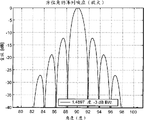
The form of accompanying drawing 12 through chart is to the explanation that makes an explanation of the xsect of the position angle of the beam pattern of receiving array and height.
Accompanying drawing 13 is azimuthal amplifier sections of the beam pattern in the accompanying drawing 12, and it demonstrates the structure of main lobe and secondary lobe.
The beam pattern that 14 pairs in accompanying drawing is almost the arranged full receiving array explanation that makes an explanation.
What accompanying drawing 15 showed is the transmitting site through selecting according to thinned array of the present invention.
The explanation that makes an explanation of the view of the xsect of the beam pattern of the emission thinned array of the embodiment in 16 pairs of accompanying drawings 15 of accompanying drawing.
The explanation that makes an explanation of the beam pattern of 17 pairs of sparse emission arrays of accompanying drawing.
18 pairs of central peak with respect to beam pattern of accompanying drawing limit average side-lobe energy to being less than-explanation that makes an explanation of the feasibility of 35dB.
The explanation that makes an explanation of the differential of 19 couples of 2D of accompanying drawing time-delay equation.
The 20 pairs of differential of accompanying drawing show the profile explanation that makes an explanation.
The explanation that makes an explanation of 21 pairs of differential delay time errors of accompanying drawing.
Accompanying drawing 22A-22C is to the explanation that makes an explanation of the embodiment of the system processor in 4 parallel beam formation systems.
Accompanying drawing 23A and 23B are to transmitted waveform coding and that do not have coding of the ultrasonic transmission that is used to the to launch frequency spectrum explanation that makes an explanation.
Accompanying drawing 24A-24C is to being used to form the processing procedure that the transmits explanation that makes an explanation.
Accompanying drawing 25A-25D is to the explanation that makes an explanation of the preferred embodiment of the filtrator that comprises coupling.
Accompanying drawing 26A-26D is to the explanation that makes an explanation of the square-wave signal that is used for third harmonic imaging and improved transmitting square wave signal.
Accompanying drawing 27A and 27B are to the explanation that makes an explanation of the matching filter template of first and second code sets that are used for Golay.
Accompanying drawing 27C and 27D are to the explanation that makes an explanation of the autocorrelation of the third harmonic of the filter template of first and second code sets that are used for Golay and basic principle.
What accompanying drawing 28 showed is the summation of two autocorrelations in accompanying drawing 27C and 27D.
Accompanying drawing 29A and 29B are to the embodiment of the template of the first and second 10 third harmonic of the Golay code sets explanation that makes an explanation.
Accompanying drawing 30A-30C is to having the sidelobe cancellation explanation that makes an explanation of output summation.
Specific embodiments
The purpose that beam forms system is the signal that is received in imaging point is accommodated in the sensor array.Through forming in the device at beam suitable time-delay is inserted in the wave front of on specific direction, propagating, the signal that reaches that comes from the load direction increases continuously, and the signal that comes from simultaneously on other directions does not increase continuously or is eliminated.For real-time three-dimensional applications, concerning each sensor element, separated electronic circuit is necessary.If what use is traditional carrying into execution a plan, consequently, along with electron device rolls up, the increase of number of elements and cost thereof also can roll up.In general, high-resolution beam forms the cost of device, size, and complicacy and power requirement can be avoided through the system of solution.For the ultrasonic imaging of real-time three-dimensional high definition rate was used, it was essential that the controllable two dimensional beam profile of the electronics direction that the computing rule of suing for peace with time-delay is the basis forms processor.
The notion of the adjustable conformal sound lens of electronics is the plane " sheet " that the surface of the sensor array of 2D is divided into less relatively subarray.As in the U.S. the 6th; That kind described in 292, No. 433 patents, its full content is incorporated this paper into through quoting as proof; And as in accompanying drawing 1, being explained; Planar chip/subarray 120 need be done enough for a short time, so that within object is placed on traditional field range that forms images the time, and the radiation of injecting towards each " planar chip " 122 that comes from object can be handled through the approximate value in far field.The time-delay element that adds is merged the processing procedure as subordinate phase; So that allow whole subarrays to be added up continuously (promptly; The beam that all near fields form can obtain through simple time-delay, and afterwards the output that comes from all subarrays is added up).The beam of delay accumulation form device allow each subarray all " towards " signal that emits from specific direction.Through regulate with array in the relevant time-delay of each element, the direction of array can control to the direction towards radiation source through the direction of electronic type.Therefore, be not to be towards as in the direction that 124a saw, but the direction of planar chip 120 can be controlled on the different direction 124b.The requirement that is used for satisfying the delay line in each element of subarray can be to be less than 100 stages.Focus on for last near field, have only the long delay in whole the adding up to need.
The beam formation device system that can control for service orientation comes the scan image plane, can use at the processor shown in the accompanying drawing 2.Raster scanning 260 can be used for coming scanning imagery plane 262 through the direction controlled sensor array 264 of 2D.
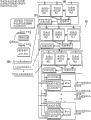
The detailed chart that the controllable beam of electronics according to the present invention forms system shows in accompanying drawing 3A to some extent.This system is formed by overlapping parallel time-delay beam in groups that processor 330-330N formed.Each processor 330 comprises the sub-arraybeamformer 332 of two part: 2D; It is used for the beam direction control/focusing in far field; With additional delay process device 334, form with the hierarchical near field beam of the output that allows to come from each corresponding subarray.Subarray 332 comprises the programmable delay line 340 of m-, and it has tap selector 342, Port Multiplier 344 and the output 346 that adds up.As in accompanying drawing 3A, can seeing; For the system with n subarrays, the time-delay of the near field of the programmable subordinate phase that n-is parallel is to be used for independent delay adjustedly, and it can be changed through A/D converter 352; To allow all n-and line output to add up 354 continuously; In turn, the output that adds up is filtered 338, and the 3D imaging of target target is provided.The operation of processor 336 control subarrays.
Accompanying drawing 3B shows is the use that digital beam with subordinate phase forms the scanner head of device.In this embodiment; The beam of a plurality of N subarrays forms device 400, and in preferred embodiments, they can be the beam formation devices near field; Each signal from m sensor element all has independently delay line respectively; Their output is added up, and forms device 420 thereby offer beam, so that this beam formation device can be a kind of legacy system with traditional processor 480.460 pairs of beams of separated subarray processor form device 400 and control.
If do not use this hierarchical far field of subarray before this and be that the near field beam forms scheme afterwards, for the 2D array of 80x80 unit element, the cable of forming through 6400 line electric wires is connected to sensor array in traditional beam formation system.Shown in accompanying drawing 3A, the quantity of the input of the processor of each subarray equals the total quantity of the time-delay element in subarray, and each subarray only has an output.To subarray overlapping in groups in the quantity of input equal the quantity of the array element of 2D; And the quantity that comes from the overlapping output in groups of subarray equals the quantity of the sum of sensor array element divided by the subarray element; Promptly; With reference to the quantity of the overlapping output in groups that comes from subarray of input quantity is that the factor of the size through equaling subarray reduces, and for instance, forms principle if select to use the subarray of 5x5 to carry out this hierarchical beam; After the subarray beam of phase one formed, the sum that need be used to be connected to the beam-forming electric wire near field of subordinate phase reduced through factor 25.More detailed says, as being mentioned hereinbefore, does not use the subarray beam of this 2D to form, and needs to use 6400 electric wires that the 2D sensor array of 80x80 unit element is connected in traditional rear end beam formation system.At first use the subarray processing overlapping problem in groups of 5x5, the quantity of line that need be used for being connected to the beam formation system of rear end reduces to 256.On basis of the present invention; In a kind of sub-arraybeamformer of 5x5 unit element 256 piled up and can be integrated on the scanner head in the lump with the 2D array of 80x80 unit element; Therefore, a kind of cable of being made up of 256 electric wires is enough to integrated scanner head is connected in the beam-forming system near field of rear end.Importantly, should be noted that the near field formation processor of 5x5 subarray can easily be integrated in undersized silicon (Si) integrated circuit, 8 such 5x5 sub-arraybeamformers can be integrated on the substrate.In this embodiment, have only 32 substrates or substrate still less to be integrated on the scanner head, thereby the quantity of electric wire is reduced to 256 from 6400.
The disposal system that beam forms device is a kind of time domain processor, and it can handle the return message of large-scale 2D array simultaneously, and low-power is provided, and highly integrated beam forms the device system, and this system can handle the whole arrays in portable system in real time.Detector with the support matrix 2D of system array of 192 parallel receiving cables is used for real-time 3D/4D imaging applications, and hierarchical multistage beam forms and can in lower powered miniature ultrasonic wave system system, use.
Accompanying drawing 3B proves explanation to hierarchical beam-forming structure; Wherein the beam of one group of adjacent receiving element forms in two stages, to accomplish and carries out, that is, and and as far as each receiving element; Be not to use single long delay; And be to use a kind of long delay of sharing by the whole element in the group, but each all has the weakness of oneself, and programmable time-delay is positioned at before the long delay.In each group, be accumulated in together from the output of each short time delay, be applied to afterwards on the shared long delay.The group of adjacent receiving element with characteristic of this shared long delay is defined as " subarray " in the sensor array.For instance, for the application of the real-time 3D imaging of having used the 2D matrix array, subarray can be the small array of the adjacent cells element of a kind of 4x4 of having or 5x5.The programmable delay of phase one in such subarray is integrated into the inside of sensor detector; Then, the output that adds up from each subarray is connected on the back-end processor.Therefore, for the 2D array (3072 perhaps more sensor element) of 64x48 position, form, only have 192 I/O cable components to be used to preceding end detector is connected in the processor of rear end if the subarray of 4x4 is applicable to the beam of phase one.
In a preferred embodiment, hierarchical beam forms and also can be applied in the array of one dimension (1D), to be applicable to real-time 2D imaging applications.For instance, for a kind of 128 1D array, the group that 8 adjacent elements are formed can be combined as a kind of subarray.In each subarray, each element in 8 elements all has the programmable time-delay of himself short-term, and afterwards, the output of 8 time-delays is accumulated in together and is adapted on the shared long delay.Importantly, it should be noted that two kinds of diverse ways can be used for carrying into execution a plan of two such stages.In first carries into execution a plan; Time-delay when whole beam-forming circuit comprises in short-term with length, they all are placed in the processor of rear end, therefore; For 128 1D array, 128 connection cables are used as the I/O cable between sensor detector and the back-end processor.A kind of carrying into execution a plan of can replacing is the inside that all subarrays all is integrated into sensor detector; That is, for 128 array, 16 all subarrays processors; Wherein each all has 8 programmable time-delays; All be integrated among the sensor detector, therefore, only need 16 cable components just can be connected on the processor of rear end by the detector that front end is integrated.In the rear end, only need the beam formation circuit of 16 long delays just can accomplish beam-forming function.Likewise; For for being integrated with 88 64 the array of processor of subarray in the detector; Back-end processor can be reduced to only has 8 beams formation circuit, only needs 8 cable components just can the integrated detector of front end be connected in the processor of rear end.Furtherly, lower powered radiating circuit and A/D converter can be integrated in the detector of front end, so that can be connected in the processor of rear end through the detector of a kind of wireless on-link mode (OLM) with front end.Wireless USB link or FireWire link all are operable.
Accompanying drawing 3C explains to the structure of the 2D sensor detector 485 of the 64X48 position of subarray processor with 4X4.The 2D array 487 of 64X48 position can comprise 48 rows' of lattice in the 1D array stacking form, and each all has 64 unit elements.Connection on each element in 64 unit elements in the 1D sensor array realizes through flexible electric wire that all therefore, the head assembly of sensor can comprise sensor array and 48 flexible electric wires 486 of 2D.Shown in accompanying drawing 3C, each subarray all comprise the 4X4 unit element (perhaps other rectangle or 2D geometric shape, preferably; Each subarray has at least 16 unit elements to 256 unit element); Article 48, flexible electric wire is divided into 12 groups, per 4 adjacent flexible being wired on the circuit board that prints, promptly; Being discharged to the corresponding flexible electric wire of 4 rows with 1 in the 1D sensor array all is connected on first printed circuit board (PCB) 488; With 5 be discharged to 8 row corresponding flexible electric wire be connected on second printed circuit board (PCB) 487, the rest may be inferred, up to 45 be discharged to 48 row corresponding flexible electric wire be connected on the circuit board of the 20 printing.An end of the flexible electric wire of each bar all is connected on the sensor base unit, and the another one end of flexible electric wire is connected on 64 the flexible electrical wiring connector that is installed on the printed circuit board (PCB).On the circuit board of each printing, the subarray processor 489 of 16 4X4 unit elements and the substrate 491 of high pressure Port Multiplier are arranged.The processor of subarray is made up of 16 parallel programmable delay lines; Each bar all has the prime amplifier of low noise in its input; Form with separated programmable multiplier and apodizer, and the output of 16 multipliers is accumulated in together to form single output.On each circuit board, the multichannel substrate of high pressure is also arranged, so that allow the sensor of 4X64 position both can in emission mode, operate, also can in receiving mode, operate.The substrate 490 of storer also can be installed on each circuit board that prints, so that store programmable time-delay for each bar delay line.Power cable also is provided and is connected to the digital input 492 on each circuit board that prints through interface 495.
In accompanying drawing 3C, also can see equally; The sum that beam formation processor on printed circuit board (PCB) is used to the reception base unit of 64X4 provides the beam of subarray to form function; It is divided into 16 subarrays, and each all is made up of the 4X4 base unit.In 16 the subarray processor each can be carried out beam and form function, that is, the time-delay of time and accumulation function, 16 receptions are integrated on the printed circuit board (PCB).What show among the accompanying drawing 3E is the microphoto of the sub-arraybeamformer substrate of 16 passages, and for each transponder pulse, substrate can form the beam that 4 orders link to each other for 16 receivers.Substrate is that double-layer polyethylene four craft of metal dealing with 0.35um are the basis.The size of the substrate that is used to explain is 1.2mm x 0.6mm.Therefore; It approximately is on the 1.2mm X 5mm substrate that 8 such 4X4 subarray processors can be integrated into a size; So it is just passable that circuit board only needs two such subarray beams to form substrate, each substrate all comprises the subarray processor of 8 4X4.
In such substrate, exist 16 tap delay lines, each bar all receives the feedback that comes from its corresponding receiving element.In the process of the receiving mode after transponder pulse, 4 beams that order links to each other, they are the output that adds up that comes from 16 tap delay lines, on sampling record, form.The tap output of each bar delay line all is to control through the multiplex memory buffer of the time-devision system of 4 beams.Each new numeral is upgraded, and corresponding nondestructive induction time-delay sampling is at the enterprising line item of tap delay line.4 numerals are upgraded and to be applied to successively on the memory buffer, and afterwards, 4 time extension samples of each beam in 4 beams are by record successively.
Before the scanning beginning, the initial tap position of each bar delay line all is in storer, to confirm in advance.In the process of receiving mode, when sampling record each time, the echo that returns is taken a sample, and is recorded on itself corresponding delay line.Multiplier is integrated on the output terminal of each tap delay line, so that correction of the flank shape, the change mark function of beam are provided.For instance, if the centre frequency of sensor is 2Mhz, the tap delay line is 8Mhz to the SF of echo so.Tap output is sequentially responded to the speed of 32Mhz to non-destructive, so that produce 4 beams.That is to say, after echo is loaded on the delay line, after the 32ns; Article one, the tap of the time-delay of the delay line of beam sampling is exported by record, and is applied on the multiplier, after the other 32ns; The tap output of the time-delay of second beam is also recorded on the multiplier; This program is proceeded, and after 128n, the output of the tap of the 4th beam goes on record.The output of 16 multipliers is accumulated in together so that form single beam with the speed of 32Mhz.Importantly, it should be noted that dynamic focusing, each beam needs two digital updated spaces; One is applicable to the tap renewal, and another is applicable to insertion.In such substrate, each passage all has analog input and numeral output; It is on-chip that two updated spaces are that order is loaded into.In order to support the order output of 4 beams; Two digital updated spaces in each beam all are to come dynamically to be loaded into on-chip with the speed of 64Mhz, and the beam that therefore allows to carry out continuously with the SF of the analog input of 8Mhz subarray forms function.If range depth is 15 centimetres, the 2Mhz detector carries out repeated sampling 4 times, and the beam that receives so forms sum and comprises 2000 points.In this embodiment, the storer on the circuit board that in accompanying drawing 3C, shows is of a size of 64x4x4x2x2000=4Mbits or more.More concrete is, can use the method for compression to reduce the size of storer.
Typical ultrasonic sensor uses identical unit to transmit and receive.The transponder pulse of high pressure is sent in the specific unit, and the echo that comes from same unit turns back in the system through identical cable.
In some applications, it is desirable to, perhaps must use separated unit to transmit and receive.In such application, different sensor is used to transmit and receive, so that transmitter all produces different frequency responses with acceptor unit, i.e. first frequency response and be different from the second frequency response of first frequency response.This is to be useful especially as far as harmonic imaging, and receiver centre frequency wherein is twice or three times of transmitter centre frequency.The emission Port Multiplier (TR_MUX) that is integrated in the circuit substrate allows to use an independent cable to be connected on radiated element and the receiving element; This realizes that through high pressure conversion is provided fast in transmit cycle, high-voltage switch gear is connected to cable on the radiated element fast; Afterwards in receiving cycle; Be connected to again on the receiving element, as shown in the accompanying drawing 3F (1), the high pressure Port Multiplier substrate that can be purchased off the shelf can not be applicable to this application; This is because they mainly are applicable to the versatility of the unit in the selection of aperture, in the ultrasonic scanning line boundary, a kind of process slowly can take place.In order to support the conversion between transmit cycle and the receiving cycle, need the switching time of switch approximately less than a wave period or a small amount of wave period, otherwise will numerous idle times that can not form image occur at the near surface of sensor.For instance, the opening of the switch of 1 microsecond can change reception into from emission in a wave period with the transmission frequency of 1MHz, perhaps two wave periods when transmission frequency is brought up to 2MHz.This helps received signal is amplified, shown in accompanying drawing 3F (2).
A kind of application need is that the application of the transmit/receive switch that is positioned at detector at a high speed is the detector array of a kind of 2D in addition; Receiving element at this at first forms in subarray, is used for receiving the quantity of the cable shown in accompanying drawing 3F (3) with minimizing.The subarray beam forms normally a kind of low-voltage equipment of circuit, and therefore, in the process of high pressure transmit cycle, this circuit need be kept apart subarray and cable.
But a kind of in addition application is used is that the TR_MUX substrate of two-stage allows the low pressure amplifying circuit in shared emission/receiving element, to use, shown in accompanying drawing 3F (4).Same unit both can be used for emission, can be used for again receiving.Receiving signal amplified send to circuit system through shared cable before.In this case, when using high-voltage pulse, in each transmit cycle, low pressure receives amplifying circuit and from cable and unit, branches away.In each receiving cycle, unit element is connected in the amplifying circuit of low pressure, is connected on the cable afterwards.
The substrate that shows among the accompanying drawing 3G is a kind of use high-voltage CMOS treatment process (>Port Multiplier of 80V) being welded.The purpose of using is to be embedded on the sound module handle of medical ultrasonic diagnosis detector, at this two sensors unit is arranged, and transmits and receives device, and perhaps sub-arraybeamformer output is shared identical share sensor cable (COM) with radiated element.Through using two groups of high-voltage switch gears can obtain multiplier effect, bipolar signal that can handle high voltages, and also frequency is brought up to 20MHz.The opening and closing of these switches are controlled through two configuration signal (CONFIG [1:0]) and two timing signal TX_TIME and RX_TIME, and they indicate the situation when system carries out emission or receiving function.Configuration [1:0] can be used to dispose the function of via pin, for instance, and the element that exchange transmits and receives.
In the operating process shown in the accompanying drawing 3G, the switch between radiated element and the shared cable is opened in transmit cycle (TX_TIME=1), and in receiving cycle (RX_TIME=1), closes.Switch between receiving element and the shared cable cuts out in transmit cycle, and in receiving cycle, opens.The time of the opening/closing of switch, time deviation was less than 100 psecs less than 1 microsecond.What accompanying drawing 3H showed is, the microphoto of the substrate in the high pressure Port Multiplier integrated circuit of 16 passages, and it is to use the manufacture craft of micron-sized double-layer polyethylene two metals to prepare, and it is of a size of 14mm x 8mm.
64 1D array of processor with subarray of integrated phase one also can use the design proposal among the accompanying drawing 3C to carry out; But what need eliminating is; 64 single sensor array 491 is connected on the flexible electric wire 497; One end of flexible electric wire is connected in each element of sensor unit, and an other end of flexible electric wire is connected in the flexible electrical wiring connector of 64 lead-in wires.Connector is installed on the circuit board of printing.On printed circuit board (PCB), the subarray processor of 88 unit cells is arranged.Each subarray processor all is made up of 8 programmable delay lines; Each bar delay line all has the prime amplifier of the low noise that separates separately, and at the output terminal of delay line, an apodizer is arranged; That is, be used for the multiplier that beam forms function.The output of 8 multipliers is accumulated in together, so that form single simulation output.The substrate of high pressure Port Multiplier circuit also can be included in the circuit board of printing, so that allow 64 sensor both can under emission mode, operate, also can under receiving mode, operate.The substrate of storer also can be installed on the circuit board that prints, so that store programmable time-delay for each bar delay line.The power cable and numeral input that are connected on each printed circuit board (PCB) also are provided.
Accompanying drawing 3D shows is the embodiment preferred with 64 of integrated subarray processor (perhaps more, for example, 128 or 256) 1D arrays 496.In this carries into execution a plan, use be not printed circuit board (PCB), but subarray treatment substrate 499a, the substrate 449b of high pressure Port Multiplier circuit and the substrate 449c of storer are directly mounted to flexibly in the P.e.c. or in the cable (497,498).
What can replace is, beam forms processor and can be installed on the printed circuit board (PCB), so that be that 64 receiving elements provide the subarray beam to form function, these elements are divided into 8 subarrays, and each subarray all is made up of 8 adjacent elements.In the processor of 8 subarrays each can be accomplished beam and form function, that is, the time-delay of time and the function that adds up, this is because 8 adjacent receiving elements all are integrated into the cause on the circuit board.What accompanying drawing 3E showed is the microphoto of the sub-arraybeamformer of 16 passages, and for each transponder pulse, substrate can form the beam of 4 orders for 16 receivers.Substrate also uses the treatment process of 0.35 μ m double-layer polyethylene, four metals.The size of this substrate is 1.2mm x 0.6mm.As in embodiment before, it approximately is on the substrate of 1.2mm X2.4mm that 4 16 such subarray processors can easily be integrated into a size, and therefore, it is just passable that circuit board only needs such subarray beam to form substrate.
As before the dynamic focusing mentioned, each beam all needs two digital updated spaces; A renewal that is used for tap, another one are used for inserting.In order to support the order output of 4 beams; The updated space that is used for two numerals of each beam all is to come dynamically to be loaded into substrate with 8 times input sample speed to go, thereby permission continues to accomplish the beam formation function of subarray with the sample rate of analog input.If range depth is 15 centimetres, the 2Mhz detector carries out repeated sampling 4 times, and the beam that receives so forms sum and comprises 2000 points.In this embodiment, the storer on the circuit board that in accompanying drawing 3E, shows is of a size of 64x4x2x2000=1Mbits, can use the method for compression to reduce the size of storer at this.System described herein can conduit or detector use in the lump, said conduit or detector are to be applicable to be inserted into the image (4D) that forms heart in the body cavity or other internals' image.Detector or conduit tube component can comprise as the circuit case in numerous beam formation device described herein.
Existing medical ultrasonic system with matrix array can provide state-of-the-art 3D (RT-3D) ultrasound wave drawing aroused in interest along real-time 2D imaging.Compare with the 2D image; The major advantage of RT-3D image comprises short acquisition time; Reduction is to operating personnel's dependence, and has lines that do not connect in the skilled control chart picture to extract the ability that any amount of needed view carries out data analysis.More detailed says, can use the 3D technology to come more accurately to obtain relevant for left ventricular mass and the mass data of penetrating blood quantity.Although term " in real time " all can be suitable in all 3D Echocardiogram appearance technology of present feasible; Importantly; Need recognize the scanner in current use, " 3D in real time " refers to direct realtime graphic, and it obtains does not need Electrocardiographic gate.Yet such real-time 3D imaging has partial volume, and it is not suitable for left ventricle is carried out to picture.
In order in current scanner, to obtain the 3D rendering of whole volume, cardiograph is used to carry out gate control to obtaining image.4 to 7 sub-volumes obtains through 4 to 7 cardiac cycle, merges afterwards obtaining complete data set, as shown in the accompanying drawing 4A-4D.Volume that it should be noted that healthy adult heart is normally at 200-500ml/m
2Within the scope.Please refer to; For example; People such as Chikos " Visual assessment of Total Heart volume and Specific Chamber Size from Standard Chest Radiographs; " Am.J.Roentgenol 128:375-380, in March, 1977, its full content is incorporated this paper into through quoting as proof.Therefore, it is desirable to, on the basis of the pulse train of shallow table transmission, in order to obtain the 3D rendering of adult heart, need be to greater than 200ml/m
2Volume carry out imaging operation.So sensor array has an aperture, it is enough to be used in transmitting and receiving the signal within roughly synchronous volume range, promptly less than the scope of 1 cardiac cycle.
That kind as indicated, approximately 128X96 bar beam is used to provide the complete coverage of left ventricle.In traditional carrying into execution a plan, in the process of first cardiac cycle with cardiograph gate control, 32X96 bar beam is used to obtain part 3D rendering (accompanying drawing 4A).In second cardiac cycle, the beam of second group of 32X96 is used to cover the adjacent part of cardiac image, accompanying drawing 4B.Persister is proceeded (accompanying drawing 4C-4D), up to the 4th cardiac cycle with cardiograph gate control; Obtain the decline of cardiac image afterwards.This four width of cloth image is combined in together so that complete 3D rendering to be provided.After the order that has write down a plurality of cardiac cycles, this technology provides large-scale fan-shaped angle and has produced the image of whole volumes.Yet, be accompanied by and move the manuscript picture that may occur sewing up, and in suffering from cardiac arrhythmia and dyspneic patient, occur, thereby cause non-diagnostic image.Therefore, the current 3D technology of in ultrasound wave record aroused in interest, using approaches real-time, but is not to be real real time record.
The preferred embodiments of the invention produce 16 scanning beams for each transponder pulse, and the result is, it is forming real " 3D in real time " image with 128X96 scanning beam with the speed of 6 volumetric images of 3D of per second at least.The velocity of sound in tissue is about 1500 cels, about 200 microseconds when passing the degree of depth and be 15 centimetres the round trip propagation time of sound wave.3D imaging for comprising the for example heartbeat of left ventricle and right ventricle shown in accompanying drawing 4E, needs 128x96 bar scanning beam that large-scale fan-shaped visual angle is provided.128X96 bar beam is 128x96x200 microsecond=2.45 second needed total two-way time.The present invention provides 16 to receive beams for each transponder pulse, and afterwards, it allows only is the 3D volumetric image that needs time of 2.45/16=0.15 second to produce to have 128X 96 single, perhaps produces the volumetric image of 6 width of cloth 3D p.s..To produce the speed of the volumetric image of 6 width of cloth 3D p.s., scanner provides the real-time 3D diagnostic image that is used to check coronary heart disease.Therefore, the embodiment preferred per second produces the cardiac image that produces 4 width of cloth full volumetric at least.
What accompanying drawing 4F-4K showed is to be used in the system implementation scheme of at least 16 beams of each transponder pulse generation.Adopted the system of phase shifted version also can be used to obtain the imaging of full volumetric.
Used like the ultrasonic system at the detector shown in the accompanying drawing 3C and in the process flow diagram of accompanying drawing 4F, explained to some extent, wherein the 2D sensor has integrated MUX, the beam generator of storer and subarray.Subarray beam generator has the input amplifier of low noise and 504 (m) in storer 504 (1) and the scanner head 502.
Accompanying drawing 4G system explains, and said system has the 2D sensor,
The 2D sensor has had MUX integrated, and the beam generator of storer and subarray, these elements all are integrated in the detector 505 with sequence beam output 506.In this pattern, the time delays processor of rear end multiply by the speed operation of the input sample speed of sensor with q, that is, if the centre frequency of sensor is 2Mhz, detector is then with the speed repeated sampling of 8Mhz.If the processor of subarray produces the output of four sequences, i.e. q=4, back-end processor just must move with the speed of 32Mhz.The beam of subarray forms the input amplifier that utensil has low noise.
Accompanying drawing 4H is to the explanation that makes an explanation of the system with 2D sensor, and the 2D sensor has integrated MUX, and storer forms device with the beam of the subarray of the beam output that comprises sequence.In this pattern, the time delays processor of rear end is the speed operation of multiply by the input sample speed of sensor with q, that is, if the centre frequency of sensor is 2Mhz, detector is then with the speed repeated sampling of 8Mhz.If the processor of subarray produces the output of four sequences, i.e. q=4, back-end processor just must move with the speed of 32Mhz.In such scheme, what back-end processor used is the beam formation system 508 in sub-aperture, that is, n adjacent receiving cable is grouped in together, forms the beam forming device 509 of phase one, shares shared long delay line 510 afterwards.Therefore, the input to the rear end is exactly a m passage.Yet the rear end output that offers summation circuit reduces to m/n output.For instance, if sensor array is 64x 48 unit elements, the beam that a kind of 4x4 subarray can be used for subarray forms, and the total output that comes from integrated detector is the 64x48/16=192 cable, that is, and and m=192.Yet, in current carrying into execution a plan, the sub-aperture that is used be 8, that is, and n=8, the total quantity of the long delay process device of its permission afterwards is 192/8=24.The beam of subarray forms the input amplifier that utensil has low noise.
Accompanying drawing 4I is included in the element in the system shown in the accompanying drawing 4G, still, is associated with controller 514 in the preceding end detector 512.Controller can form on the tertiary circuit plate; Be connected to the circuit of outside housing 513 along wireless perhaps cable 515; External shell can with the processor interface of main system; Perhaps can be integrated in the system of transporting, perhaps can be integrated in the portable system, as described herein.
Accompanying drawing 4J shows is a kind of structure of the structure similar with described in the accompanying drawing 4H, and still, controller 514 is integrated in the middle of the front end.Promptly; Interconnective cable is a m=192 bar passage, yet the beam in sub-aperture forms device and is integrated in the back-end processing process; N adjacent receiving cable is the passage of the first formation beam; And be applied to afterwards in the time delays processing procedure of rear end, if n=8, the output that offers totalizer only is 24 passages.In addition, can select the scheme that emission substrate 517 (m) is integrated into the integrated detector of front end for use.Yet transmission channel can be located in back-end processor as the pointed that kind of accompanying drawing 4I.
The method of application of the structure among the accompanying drawing 4K is to be similar to accompanying drawing 4J, and still, in back-end processor, the parallel beam of p is that the beam in each sub-aperture forms in each of device 519 and parallel delay process device 519p and forms.Therefore, if p=4 for for each bar output beam of the integrated detector 518 of front end, can form 4 parallel beams so, each in totalizer 519s in 4 output all is accumulated in together.Here it is.16 beams are the processes how to form in communication process each time, that is, in detector, q=4 can form the beam that 4 orders link to each other, and p=4 in the rear end can form 4 parallel beams and p q=16 doubly.Note that in accompanying drawing 4K, radiating circuit also is included in the integrated detector of front end.Yet, note that launching substrate can locate in the processor of rear end.In addition, in accompanying drawing 4F-4K, can use the sensor array of a kind of 2D, this structure also can be used in the sensor array of the beam-forming 1D with sub-aperture.These systems provide the cardiac image of overall volume, and it can form the video image of the heart that comprises left ventricle and right ventricle with the video speed of per second at least 4 width of cloth full volumetric images, and preferred frame frequency is per second 6 width of cloth full volumetric images, and is perhaps more.
Accompanying drawing 5A, 5B and accompanying drawing 6A, what describe among the 6B is that the beam of 2D array of the present invention forms preferred embodiment, each in the embodiment in the accompanying drawing can reduce noise with cable because the cost that the S/N performance of raising is caused.In these carry into execution a plan, the parallel subarray beam of m form processor 520 and Port Multiplier 528 be integrated in the 2D sensor array 525 to form compact, the scanner head 500 of low noise.What accompanying drawing 5A described is a kind of like this system; Wherein compact scanner head is connected in the special-purpose processing module; In this module, m parallel prime amplifier/TGCs522, the time delays processing unit 526 of emission/reception substrate 524 and subordinate phase is encapsulated in together.Special-purpose processing module is passed through FireWire IEEE1394 or USB or pci data line 542 with principal computer 540 and is intercomed mutually.Control and synchronous operation are carried out through the system controller 544 that is arranged in processing module or shell 546.What accompanying drawing 5B described is and the similar structure of accompanying drawing 5A; Except built-in dedicated processes module; The time delays processing unit of subordinate phase uses (CDP) the able to programme time delays line 600 that is positioned at the electron region within the shell 620 to carry out specific operation, and it is connected on handle detector 660 and the counter body 648.What accompanying drawing 6B described is a kind of like this system, and the scanner head 700 of compact thinned array is connected on traditional commercially available time domain digital type ultrasound wave imaging system 700, and this system has n parallel beam and forms passage 760.Can see at an easy rate from accompanying drawing 6A that time delays processor 720 also can be carried out through using CDP time delays line 740.In these embodiments, the beam near field forms and is encapsulated in 720,780 by the identical shell of the image processing function with other.Said system is described in the PCT/US2007/014526 international patent application of submitting on June 22nd, 2007 to some extent; And indicate in the 11/474th of submission on June 23rd, 2006; No. 098 U.S. Patent application, the whole interests in these two applications are incorporated this paper into through quoting as proof.
Through changing systematically that beam forms the time-delay of device and, can be used to make up the scan image that forms with scanning angle along the echo of the sight line of expression 3D radiation source to shade along the visual angle of 2D sensor array.This system can through with 20 frame/seconds or faster the speed of big visual field continuous real-time large-area scan image is provided.Under such view speed, system can be used to show the 3D rendering of comparing with the time continuously, thereby the 4D information of scanning object is provided.Shown in accompanying drawing 7; The CDP beam forms substrate 810; The multiplex computation structure of time-devision system can be used to produce numerous beams; That is, for transponder pulse each time, overlapping 2D sub-arraybeamformer 818 and the near field time delays line of its corresponding subordinate phase in groups can both provide order adjacent numerous beam.Counting circuit produces in proper order and meets the time-delay that forms the K beam.The operation of equipment process is following: in case one group of sample echo of sampling through sample circuit 814 in delay line, locate, at time t
1, the time-delay that is used to form beam 1 calculates 812 in each module 822, and is applied on whole delay lines by parallel.The echo as sample with suitable time-delay is added up 802 and be filtered 804 successively, to form first beam.At time t
2, the time-delay that is used to form beam 2 is calculated in each module, and is applied on whole delay lines by parallel.The echo as sample with suitable time-delay is added up successively and is filtered, to form second beam.Repetitive process is up to continuous formation K bar beam.
For instance; If have the counting circuit of the addressable output of 16 sequences is to set up through the delay line of CDP subarray and subordinate phase; For transponder pulse each time, all can set up along 16 beams of different scanning angles or each in the sweep trace.For having 15 centimetres 256 pulses of the degree of depth by a narrow margin, system can form 4096 beams with 64x64 pixel resolution with the speed of 20 frame/seconds.System can programme fully; Beam-forming electron device can adapt to high resolution or higher picture frame speed through overregulating to amplify less visual field.For instance, use 192 transponder pulses with 15 centimetres of identical degree of depth by a narrow margin, system can form 3072 beams with 64x48 pixel resolution with the speed of 30 frame/seconds.
The array that 2 centimetres of x of the two dimension that described array frequency of utilization is 3MHZ 2 centimetres solves the problem in the ultrasonic imaging application.Needed resolution is half the less than the same with the aperture as far as possible big wavelength approximately, and its aperture can be encapsulated in the compact packing.For scan volume that obtains 90 degree and the influence that reduces grating lobe, therefore, a kind of height and spacing distance are desirable less than the base unit of 0.25mm, and this can form a kind of array of 80x80 base components.Use as again described in the subarray treatment technology, having the scanner head that integrated subarray beam forms the system that the near field beam control/beam of circuit and subordinate phase focuses provides a kind of special executive mode.Yet this executive mode still need be integrated into 32 subarrays substrates on the scanner head at least.A kind of random array design scheme of the hypothesis that can replace can be used to obtain such resolution, has a spot of treatment element on the scanner head of this scheme.
In order to form a kind of practice mode of thinned array, the combination of the performance of low insertion loss and wideband section is important for the imaging performance that the realization acceptable has low illumination levels.Quarter-wave is complementary with the layer with low acoustic impedance, still is that the sark of solid forms firm array fully, and it only loses 3-4dB in the process that the signal energy that receives is changed into electron energy.75% perhaps more array bandwidth is typical in this design and processes flow process.What likewise, sensor array adopted is element location and the interconnective system that is applicable to beam formation device circuit.Electron device is installed on the circuit board of printing, and it is connected on the sensor unit through flexible cable.In practice, the major part in the array element all is to use flexible cable to be connected in the output.Yet, only have the sub-fraction line to be connected on the circuit board in whole elements.However, the particular form of the connection sufficient to guarantee of a large amount of array elements active component of in final array, locating.
As the embodiment of a thinned array, suppose that 2x2 centimetre array has 256 active components, the result is that activity coefficient is 4%.
 activity coefficient of the output signal of array and noise is corresponding to the loss of the susceptibility of-13dB.In order to compensate said loss, transmitting that bandwidth is bigger is selected the susceptibility that is used to improve array.In this scheme of mentioning, susceptibility improves about 10dB.Further details about the equipment of thinned array is described in the 6th, 721, can find in No. 235 United States Patent (USP)s, and its full content is incorporated this paper into through quoting as proof.
Ensuing in the scheme is the orientation problem of the element in the array, wherein it should be noted that the periodicity of the grating lobe that will eliminate any issuable and main lobe confused.Pseudorandom or array at random also is operable (accompanying drawing 8A).The geometric configuration of the position of active component has developed into the validity that beam is formed device and has performed to maximum, simultaneously grating lobe and secondary lobe is dropped to minimum degree.Switch between numerous different array formats is used to provide the most effectively beam pattern, and this is to realize with respect to the volume of the load that is scanned or the different beam angle in zone.Therefore, first pattern is operable, and it is explained in accompanying drawing 8A to some extent, and afterwards, it is transformed into second pattern to be applicable to different scanning angles.This picks out sensor element among possibly being included near the element 880 of given element, so that scan with second angle.
The fundamental purpose of optimized method is to drop to average side-lobe energy minimum.Specifically, this can accomplish through optimized standard is assessed each other:
(1)
Weighting function W (u wherein
x, u
y) more weight is applied in the zone of the array response that requires the minimizing secondary lobe.Optimized method starts from weightless condition (that is W (u,
x, u
y)=1), and through Continuous Selection preferably weighting function come progressively to increase, it satisfies optimized standard said function.Because the reduction of the desired maximum of secondary lobe, it is must the beam form relevant with calculated in advance number, B (u
x, u
y), choose weight, so that W (u
x, u
y)=B (u
x, u
y).This will accomplish up to convergence occurring with interactional mode.
On the basis, random array can produce the distribution function of picture point, and its ratio N with main lobe and the average secondary lobe of N is the sum of the active component in the array.For the embodiment of 256 thinned arrays, resulting ratio is-13dB.Use wide band scheme can this ratio be improved 10dB.On the basis of optimized standard before, the pseudo-random position that has produced array element is (accompanying drawing 8A).
Accompanying drawing 8B is the drafting figure of array performance, the ratio between sensitivity and the intersection region, and this is for 256 the sparse sample array that frequency is 3MHZ.The ratio of peak value and the maximal value of secondary lobe is near 30dB.In order to improve this performance, system is arranged to and realizes that as far as possible the main lobe and the ratio of clutter maximize, and it has independently been revised.
What accompanying drawing 9B described is a kind of like this system, and the scanner head 900 of thinned array is connected on the digital supersonic imaging system 940 of traditional commercially available time domain, and it has m parallel beam and forms passage.Can see easily that in accompanying drawing 9A the delay process device also can be carried out through using the CDP delay line 920 in the shell 925, it is connected on the different computing machine 927.The array of m Port Multiplier 906 is used between a series of scan pattern that comes into force through software programming and system controller 940 or processor 950, change.Therefore, the different scanning angle that the pattern of a series of thinned array is selected for the target that will carry out imaging operation scans, so that the ultrasonography of 3D is provided.
Commercially available is that basic 3D imagery software can be used for visual inspection with the form, the multijet volumetric image data of operation and analysis 3D, and these data are to be provided by the adjustable conformality sound lens of electronics system.Say traditionally, use clinician that the 2D ultrasonography diagnoses to it will be appreciated that the fragment of 2D scan image, and these information are redeveloped into the 3D expression formula, to judge patient's anatomical structure through thinking through the mode of intercepting.This is crossed the range request clinician and has rich experience and human anatomy is had deep understanding.For the image with " complete " is established as the 3D structure, the clinician must consider the fragment that might occur.Even as far as a patient, check that its hundreds of fragment is a job consuming time.The 3D imagery software that is the basis with the 3D volume data helps to overcome these problems, and this is to come from the 3D expression formula of 3D anatomical structure of reconstruct that numerous scanning beam forms the patient of data set and realize through providing to the clinician.
Commercially available Software tool, for example, the KB-Vol3D in the KB-VIS technology that provides by India Chennai, it provides the demonstration of 3D characteristic and has browsed, for example:
● paint body fast
● show shaded surface
The module of shaded surface allows to make the easy imagery that becomes of the surface in proper.The surface can be through with intensity be the basis critical value set up.What can select is that the sowing type method can allow to select the specific syndeton of load.
● have the MIP (projection of maximum intensity) of radiation
● have the MPR (reconstruction of multiple plane) of dual deflection of deflection & and 3D correlativity
● the multiple cutting of the dull and stereotyped & of MRP
● crooked MPR
● operating personnel realize the color & transparency adjusted
● grow up and cubing in the zone
● have the cut-open view of dull and stereotyped volume and interactional real-time VOI
" cut-open view " instrument of use can easily be seen internal volume.Section is to be used for carrying out the intercepting fragment through volume, manifests interior zone.Through using mouse to position section easily and orientation.
VOI (load volume) instrument allows interactively real-time load volume to show.The user can make things convenient for and real-time cut-away view and the substituted volume of browsing load, and this is to realize through the mouse action of clicking and dragging.
● image is preserved with multiple form
Can be captured and change into various picture format (comprising DICOM, JPEG and BMP or the like) through the KB-Vol3D images displayed
● the image capturing that carries out with the AVI form
The imagery operation also can be captured as the AVI image, and can in systems such as Windows Media Player (Windows), QuickTime and Real Player, demonstrate.
The present invention can use the scanner head 12 that is connected on the portable computer 14 to carry out, shown in accompanying drawing 10.Ultrasonic system 10 also can comprise detector 12 is connected to the cable 16 on the processor shell 14.Some embodiment can adopt with interface unit 13, and it can comprise that beam forms device equipment.Scanner head 12 can comprise sensor array 15A (2D) and circuit case 15B, and it can encapsulate Port Multiplier and/or beam and form element, as the 6th; 106,472 and 6,869; 401, the detail content described in number United States Patent (USP) is such, its all instruction incorporate this paper into through quoting as proof.
Be applicable to that the configuration of propagating with the 2D array of the non-whole thinned arrays that are covered with array that repeat to superpose can be used for reception.For N x M cellular array, only be to have an optimized thinned array position m unit to be used to transmission, and remaining NM-m unit is used as receiving array.For instance, for the 2D array of the unit element of 40x60,256 elements are for being used as radiated element, and the position of radiated element is on the basis of selected standard, to carry out optimizedly, and remaining 2144 unit is used as receiving element.This embodiment has been simplified the needed Port Multiplier of 2D array, and wherein Port Multiplier can be installed within the shell of interface.
Accompanying drawing 11 shows is the embodiment of position of components of the receiving array 50 of the 40X60 that almost all is covered with.2400 array abdicates through the radiated element of 256 thinned arrays that 2144 receiving element positions reduce.These elements all are independently, and are not superimposed upon on the radiated element of thinned array.In preferred embodiments, the formation sum of radiated element is less than 25% of array sum, and preferably is less than 15%.
What accompanying drawing 12 showed is the elevation angle xsect and the position angle of the beam pattern in the receiving array mentioned above.With respect to central peak, first secondary lobe is approaching-13dB.With respect to peak value, grating lobe is less than-30dB.The width of considering the 2D array is greater than height, azimuthal beamwidth (part of marking and drawing with blue (solid line) is than elevation angle beamwidth (part with green (dotted line) marked and drawed is slightly narrower)).
In accompanying drawing 13, the zoomed-in view of the position angle beam pattern of being mentioned in the preceding text is explained to the detailed structure of main lobe and secondary lobe.In this case, beamwidth is near 1.5 degree.Beam pattern is almost with identical near the beam pattern of the full 60x40 unit element of row.The beam pattern of receiving array shows in accompanying drawing 14 to some extent.As what mentioned in the preceding text, the thinned array of reception is made up of 2144 unit.Because 256 (emission) element has been reduced at the center of array, therefore there is not secondary lobe here.
Accompanying drawing 15 demonstrates the embodiment of the final cell location of 256 emission thinned arrays 60.The location of 256 unit elements is to be limited on the center of 32X32 unit of the full array of whole rows.These unit are separate, and not can with the unit overlaid of receiving array.The viewgraph of cross-section of the pattern of emission thinned array shows in accompanying drawing 16 to some extent.With respect to central peak, first secondary lobe is approaching-17dB.With respect to peak value, grating lobe is less than-27dB.The optimization algorithm of thinned array is minimised as side-lobe energy+/-45 degree on the elevation angle, and is minimised as+/-45 degree.
The beam pattern of the sparse emission array shown in 17 pairs of accompanying drawings 15 of accompanying drawing is explained.The emission pattern is designed on the pyramid of the unified beam material that covers 4x4.Emission thinned array is made up of 256 subclass in full 2400 the array (filling up near 10%) of whole rows.The algorithm for design of the position of emission/receiving array requires to repeat to surpass 750 so that the side-lobe energy that transmits and receives is minimized to+azimuthal scope of/-45 degree within, within the elevation coverage of+/-45 degree.Shown in accompanying drawing 18, after repeating 750 calculating, for the central peak of beam pattern, the position of final sparse emission array element is limited in average side-lobe energy and is less than-35dB.
Lower powered ultrasonic system can electron scanning two dimension, 2D, matrix array, producing real-time three-dimensional, the volumetric 64X64 of 3D, 4096 image, it is desirable carrying out beam scanning with per second greater than the speed of 20 width of cloth 3D renderings.As far as transponder pulse each time, system has 16 abilities that receive beams that produce.In addition, design proposal can drive a peacekeeping and partly tie up array, and also can support to be used for the wide band coding transmitted waveform of pulse compression, to improve the susceptibility of system.Wide frequency band can use waveform (PN order) chirped and coding, and it can extend the length that lower powered emission uprushes and the loss of longitudinal frame can not occur.The combination of these characteristics can cause having the imaging array of electronic system, and it will be able to be suitable in portable handheld device.
It is a kind of processor of time domain that beam forms the device disposal system; It will handle the return message of large-scale 2D array simultaneously; Low-power, highly integrated beam forms device and provides the real-time processing to whole array, thereby the device cheaply that can hand is provided.
Exist tight demand now to the real-time 3D ultrasonic imaging system that uses the 2D matrix array.In this part, the reception beam of the minimum number that in ultrasonic system, is used to support real-time 3D imaging is formed passage analyze.Can see that 192 parallel receive beams of minimum number form passage and are used to support a kind of array with rational size, for example, the array of 48x64 position.
System implementation example with the adjustable conformality sound lens of electronics is divided into the surface of 2D sensor array on the plane " sheet " of small-sized relatively subarray; It can be through the 6th; 292, No. 433 United States Patent (USP) prepares, and the content of said patent is incorporated this paper into through quoting as proof; Beam in the whole array forms and can be divided into two stages, at first is that the subarray beam of small-bore forms, and is that the wide-aperture of subordinate phase added up from the output of each subarray continuously afterwards.As the content described in planar chip/subarray, they can make enough little, so that when object is placed among the visual field of imaging system, and towards each plane " sheet ", this can handle through the use far-field approximation from the incident radiation of object.Yet the beam near field forms the part in the practical operation that can become subarray beam formation system, so that allow the more use of wide region.Extra time-delay element also can merge in the processing procedure of subordinate phase, can be added up continuously to allow whole subarrays.The beam of delay accumulation forms device and allows each subarray can " find " signal from specific direction.Through the time-delay that is associated of each unit in adjustment and the array, the discovery direction of array can redirect to the direction of radiation source electronically.The delay line that in each unit of subarray, uses can be less than 100 stages.The long delay that is only used for all adding up need use in final near field focusing.The detail flowchart that electronically controlled beam according to the present invention forms system shows in the accompanying drawing 14A of the 6th, 292, No. 433 patents of the U.S. to some extent.This system by overlapping in groups and the beam of line delay form that processor forms.Each processor all comprises two parts: the beam of 2D subarray forms device, and it is used for the beam direction control/focusing of small-bore and extra delay process device, forms to allow that hierarchical near field beam is carried out in the output that comes from corresponding subarray.As what seen among the accompanying drawing 14A that is mentioned hereinbefore; Has the m subarray; The system of the near field time delays of the parallel programmable subordinate phase of m all is necessary in each time-delay is regulated; So that allow all m and line output to be added up continuously, in turn, the 3D rendering of the target target that this output that adds up provides.
People can easily understand; Do not use and thisly be to use the small-bore earlier and use wide-aperture hierarchical subarray beam to form scheme subsequently; For the 2D array of a kind of 80x80 position, the cable of being made up of 6400 electric wires is used to sensor array is connected in traditional beam-forming system.As mention hereinbefore the 6th; 292; The sum of the time-delay element in that kind of being seen among the accompanying drawing 14A of No. 433 United States Patent (USP)s, the quantity of the input in each subarray processor and subarray is identical, and each subarray only is to have an output.This that is to say, the quantity of the input in the subarray equals the quantity with the subarray sensor associated.The quantity of the output of subarray equals by the quantity of the quantity of subarray divided by the element in total sensor array.For instance, if people select for use is that a kind of 5x5 array is carried out this hierarchical beam and formed system, after the beam of the subarray of phase one formed, the sum of electric wire of beam shape that need be connected to the near field of subordinate phase was to deduct factor 25.More concrete is, as preceding text mention, do not use the subarray beam of this 2D to form, need the 2D sensor array of 80x80 be connected to traditional rear end beam through 6400 electric wires and form.At first use the subarray processing procedure of a kind of 5x5, the number of electrical lines that need be connected in the beam formation system of rear end reduces to 256.On the basis of this embodiment of the present invention; Overlapping can be integrated on the scanner head in groups of the unit sub-arraybeamformer of 256 5X5 with the unit 2D array of 80X80; Therefore, the cable of being made up of 256 electric wires is enough to that integrated scanner head is connected near field, rear end beam and forms in the system.
Importantly, the beam of small-bore that it should be noted that the subarray of 5X5 forms processor and can easily be integrated in the undersized silicon integrated circuit, and the beam of the subarray of 8 such 5X5 forms and can be integrated in the integrated circuit.Note that bringing up to the subarray of 8X8 corresponding with the subarray of 3X3 is that subarray has 9 to 64 sensor elements usually.For foursquare array geometry, preferred range is between 4X4 and 6X6 array.Rectangular subarray also can preferably use 3x4,4x5, the perhaps array of 4x6.It should be noted that and to use 1/4 λ error minimization criteria.Only there is the equipment of 32 integrated circuit need merge on the scanner head, can the quantity of cable be eased down to 256 from 6400.Likewise, for the unit 2D array of 64x48, at first in the shell of sensor, use the subarray of 4x4 to handle stacking, afterwards, the beam-forming number of channels in rear end reduces to 192.
In the present invention, the beam-forming preferred embodiment of 2D array, each minimized noise all is able to describe in accompanying drawing 4-6B with the cable loss that improves signal-to-noise performance.In these embodiments, the stacking that the beam of m parallel subarray forms processor all is integrated in the 2D sensor array, to form the scanner head of compact low noise.What accompanying drawing 4 was described is a kind of like this system, and the scanner head of compactness wherein is connected in the special-purpose processing module, m wherein parallel prime amplifier/TGC, and the delay process device of emission/reception substrate and subordinate phase all is encapsulated in together.Described dedicated processes module is through FireWire, and USB or pci data line intercom with principal computer 540 mutually.Control and synchronous operation are to carry out through the system controller that is arranged in processing module.Accompanying drawing 5 is described be with accompanying drawing 4 in the identical structure of structure, just in the inside of the processing module of special use, the delay process device of subordinate phase is to carry out specific execution through the programmable time delay line that uses electron region.What accompanying drawing 6A and accompanying drawing 6B described is a kind of like this system, and wherein compact scanner head is connected to traditional commercially available m parallel beam that have and forms in the time domain digital type ultrasound wave imaging system of passage.Can see easily that in accompanying drawing 6A and accompanying drawing 6B, the time delays processor also can be carried out through using the CDP delay line.
In the preferred embodiment of system, wide-aperture beam formation system is integrated within the shell of primary processor of ultrasonic imaging system, as shown in the accompanying drawing 19-24B.
The velocity of propagation of sound in tissue is about 1500 cels, and therefore, the round trip propagation time that sound wave penetrates 15 centimetres of degree of depth is about 20 microseconds.For real-time 3D imaging, the 64x64 bar scanning beam image that is provided for diagnosing with speed at least greater than the volumetric image of per second 20 width of cloth 3D.For each bar emission beam, real-time 3D imaging system can be at least 16 beams of transponder pulse formation each time, to support the requirement of preferred 3D frame frequency.In this part, the multiplex beam of a series of time-devision system forms and parallel beam-forming the carrying into execution a plan of synchronous time domain can both be able to solve.
In order to satisfy the requirement that scans with 16 beams, can use the textural association form of series connection and parallel connection, promptly; The technology that system uses the beam of the time-devision system multipath transmission sequence of front end to form the unit forms two beams; Be 8 parallel beams formation devices on back-end processor afterwards, perhaps system can form the beam of 4 sequences for the beam of each sequence output, afterwards; Back-end processor forms 4 parallel beams, or the like.
Through changing systematically that beam forms the time-delay of device and, can be used for making up with the formed scan image of scanning angle along the close echo of the sight line of expression 3D radiation source to shade along the visual angle of 2D sensor array.This system can through with 20 frame/seconds or faster the speed of big visual field continuous real-time large-area scan image is provided.Shown in accompanying drawing 7; Beam at CDP forms in the substrate; The multipath transmission computation structure of time-devision system can be used to produce a plurality of beams; That is, for transponder pulse each time, the beam that can provide many orders to link to each other overlapping in groups of 2D subarray with near field delay line its corresponding subordinate phase.Counting circuit produces the time-delay that is used to form K beam in proper order.Equipment is operated through following sequencing: in case one group of echo as sample is loaded on the delay line, at time t1, the time-delay that is used to form beam 1 is calculated in each module, and is applied on whole delay lines by parallel.The echo as sample with suitable time-delay is added up successively and is filtered, to form first beam.At time t2, the time-delay that is used to form beam 2 is calculated in each module, and is applied on whole delay lines by parallel.The echo as sample with suitable time-delay is added up successively, to form second beam.Repetitive process is up to continuous formation K bar beam.
For instance; If having counting circuit and the subarray of processor and the delay line of subordinate phase of the addressable output of 16 sequences combines; So for transponder pulse each time, all can set up along 16 beams of different scanning angles or each in the sweep trace.For having 15 centimetres 256 pulses of the degree of depth by a narrow margin, system can form 4096 beams with 64x64 pixel resolution with the speed of 20 frame/seconds.System can programme fully; Beam-forming electron device can adapt to high resolution or higher picture frame speed through overregulating to amplify less visual field.For instance, use 192 transponder pulses with 15 centimetres of identical degree of depth by a narrow margin, system can form 3072 beams with 64x48 pixel resolution with the speed of 30 frame/seconds.
The purpose that beam forms system is that the signal focus that reception comes from picture point is listed to sensor array.Calibrate with the specific square wave front of propagating through in beam formation device, inserting suitable time-delay, the signal that comes from the direction of load is added continuously, and those signals that come from other directions perhaps are not cancelled by continuous adding.Flight time from the radiation source to the focus can calculate, and can be stored in the storer for each passage on the parallel a plurality of directions that reach.In traditional carrying into execution a plan, isolated circuit must be applicable to each bar beam; For the multijet system, the result is the increase along with beam quantity, and electron device and cost also roll up.For instance, the beam that is used for 192 linear cell arrays forms 192 parallel delay lines of needs, and each bar all has programmable time-delay length greater than 128 λ.In order to form 4 parallel beams, for instance, need add up to 768 programmable delay line.Be used for the multijet electron device in order to simplify, described here is the beam formation system in a kind of hierarchical two stages.
Hierarchical beam-forming notion is that the calculating with the flight time is divided into two parts: first is the beam-forming time-delay in short-term in the small-bore of low resolution, is high-resolution wide-aperture beam-forming long delay afterwards.What accompanying drawing 19 was shown is the 3D differential time-delay equation that is used for the 2D array.The representative of this equation be, at array element (x
m, y
m) in differential time-delay as the function of scope and angle Theta and Phi (for the center of 2D array).Equation can pass through whole y
m(y is the position of unit) is set at 0 and is reduced to the 1D array.Differential time-delay can be through being that Phi=0 is restricted to single plane (rather than three-dimensional) with angle initialization.
Prove the operating process of the time-delay in two stages for example, the whole unit that are necessary in 1D and the 2D array produce the outline line of differential time-delay.In order to realize this purpose, the equation of differential time-delay is calculated, and the time-delay of whole differential is as the function of angle Theta and Phi, within given scope, they are listed in the form.For instance, shown in accompanying drawing 20, what draw out is near the outline line of the unit differential time-delay the center of 2D array.
In the delayed time system in two stages, the tabulated data that comes from the previous steps is broken down into rough time-delay and accurate delay.For the decomposition of confirming how to delay time roughly with accurate delay, maximum differential delay time error is confined (is typically be set at have maximum differential delay time error be less than or equal 1 sampling).The time-delay of listing in the form (coming from previous step) also can be used to determine when the activation receiving element.What for instance, accompanying drawing 21 was described is the function of differential delay time error as a small amount of unit scope.The worst situation is, differential time-delay (with the blue point of drawing) is to be applicable to that the center that is positioned at the 2D array gets unit (Theta=+45 degree, Phi=+45 degree), and it attempts to receive from the Theta=-45 degree, the view data on the Phi=-45 degree direction.In this case, maximum differential time-delay is greater than qualifications (>1 sampling error); Therefore, the unit can not receive, up to scope greater than 100 samples nearly.
Accompanying drawing 22A shows is the process flow diagram that the parallel beam in hierarchical two stages forms system 958.The sensor array 960 of the two dimension of hand-held detector, the detector of 12 marks of numbering in the accompanying drawing 10 for example, its weight is less than 15 pounds, and it can join on the amplifier 962 before forming system 964 being connected to beam.Beam forms the delay line that system can comprise numerous weak points, and in summation circuit 968, they are added up continuously, and output is used to transmit long delay line 970, and they also can add up in summation circuit 972.The rough beam of phase one forms and comprises the echo that adds up continuously and return from the small-bore, for instance, and 8 adjacent receivers in this particular.Owing to the undersized reason in aperture, the time-delay length of the delay line that each bar is short only is about 8 λ.Therefore, for the input of 192 elements, can form the rough beam of 24 such small-bores.Afterwards, each bar in 24 beams all is applied to its pairing programmable long delay line that is used for the length that wide-aperture high-resolution beam forms.In order to form 4 parallel beams, need 4 described beams to form structure.As can in accompanying drawing 22A, being seen; This in hierarchical the carrying into execution a plan that forms 24 rough beams; Only need the delay line of 192 weak points, what follow afterwards is 24 long delays, and each bar all has the programmable time-delay length less than 128 λ.For 4 parallel beams, only need 192 short time delays to add 96 long delays, it provides remarkable use of having practiced thrift electron device and power.
Furtherly, in each small-bore, in the short time delay line, the control circuit of flight time is used to select come from the tap position output of the treatment circuit of electron region, and it can sense to non-destructive the output of the delay line of tap.Each receiver all has the multiplier that comes from beam shade/change mark.In each processor, whole multipliers is shared a shared output.Afterwards, the electric charge that adds up is applied in the filtrator of coupling, so that decode and echo is compressed, has the imaging pulse of the signal to noise ratio (S/N ratio) of reduction with generation.The electron region A/D converter of a kind of analog to digital (A/D) or a kind of monolithic converter all is operable, so that hierarchical adding up can be accomplished through the form of numeral.
In preferred embodiments, importantly form the digital communication connection of adopting between device output and the back-end processor at a high speed at beam.As before described content such, be converted into digital signal by the echo of the received simulation of each sensor element, this is to realize through the converter (A/D) of use analog to digital in the process of signal Processing.As form device 974 at the beam shown in the accompanying drawing 22B, A/D converter 976 can use on the input end of each bar short time delay line, and time delays is digital execution.What perhaps can select is that shown in the embodiment in accompanying drawing 22C 980, A/D converter 982 can use on the output terminal of the rough beam of each bar, and long delay can be digital execution.A/D converter can use commercially available discrete component to form; Perhaps in preferred embodiments; The A/D converter of electron region can form on the identical integrated circuit of the beam formation device with electron region, and hierarchical wherein adds up and carries out through digital mode.
In the communications field, people have produced very big interest to use coding or spread-spectrum signal.This technology is a kind of conventional application in the digital communication system of cellular basestation and drawing lines at satellite now.Shown in the accompanying drawing 23A is that a kind of frequency is the sinusoidal curve in 5 cycles of 3MHz, and this curve does not have spread spectrum decoding.A kind of perhaps system of spread spectrum through coding launches the broadband, the excitation signal of of short duration prolongation, and it has the product that limits the time-frequency bandwidth.The signal that receives is decoded, thereby so that produces the imaging pulse with improved signal to noise ratio (S/N ratio).The advantage of use coded signal is to provide and has high-resolution imaging in ultrasonic imaging system, significantly reduces the acoustical power of peak value simultaneously.These signals also can offer the signal Processing gain, and it can improve the reception susceptibility of total system.To the management of a series of modulation is that the modulation of the carrier through coded sequence is carried out.In practice process, signal can be AM (pulse), FM, amplitude, the modulation of phase place or angle.Also can be a kind of pseudorandom sequence or PN sequence, it can comprise the sequence of binary value, and this sequence is carried out repetition after the specific time cycle.
In ultrasound wave, the notion of the excitation transmitted waveform of use spread spectrum/coding comprises modulates the exomonental basic sequence of the length P of the coded sequence with code length N.The coded pulse sequence of N burst typically refers to the coding of N substrate.The sinusoidal curve of gate 3MHz with Barker [111-11] coding of 5 substrates is presented among the accompanying drawing 23B.Each " substrate " is all corresponding to 1 cycle of the transmitted waveform of gate.Therefore, it is identical with accompanying drawing 23A that accompanying drawing 23B is close to, except the period 4 be inverted.In accompanying drawing 23A and accompanying drawing 23B, what continuous lines was represented is to adopt sine wave continuously, and the cross hatch point is adopted signal, gathers 10 samples in each cycle.The pulse train of coding, its length that has is NxP, and this sequence can be through reducing peak power in the propagation medium effectively, and this is through the power spectrum spread was realized in the long time cycle.At the reception period of the back echo of spread spectrum/coding, can be used for separating to the received signal with the filtrator of pulse compression coupling, thereby produce the imaging pulse of signal with improved signal to noise ratio (snr).The SNR improvement amount of NxP coded pulse sequence is 10log (NP).Therefore, for the transmitted waveform that length is 7 the Barker coding and the burst in two cycles, can obtain the SNR of 11.4dB.Yet in native system, the waveform that transmits and receives is to be that the speed of S is carried out repeated sampling with the repeated sampling frequency.The typical repeated sampling frequency S=4 that often uses.Ensuingly afterwards be, at the end of receiver, the filtrator of coupling that has length and be the tap of NxPxS can be used to decode and be used for the echo that returns is compressed, thereby produces the imaging pulse of the signal of the SNR with improved 10log (NPS).Among the embodiment hereinbefore, N=7, P=2, S=4 can obtain the SNR of 17.5dB.
What show among the accompanying drawing 24A-24C is the method for optimizing that a kind of formation transmits.The basis sequence is the pulse of signal, as in accompanying drawing 24A, being seen.What use is the Barker coding [111-11] of 5 substrates, and accompanying drawing 24B representes is the circling round of basis pulses with Barker coding.At last, system launches the continuous wave of repeated sampling, as shown in the accompanying drawing 24C, and can be with the waveform of 6 times repeated sampling as transmitted waveform.
A kind of reception beam formation system of 192 passages has the ability that excitation waveform for each spread that emits coding forms 4 parallel beams through overcompression, and the beam shown in the accompanying drawing 25A forms a kind of system that comes to this of device system 985.In this embodiment; What use is the hierarchical beam formation structure in two stages, at first is that the short time delay of small-bore forms the output signal of device 986; It is the continuous accumulation result of echo that comes from 8 adjacent sensors; Next is, the filtrator 987 of pulse compression coupling is used to decode to the received signal, and compressed signal 988 is applied on the long delay line to form complete beam-forming demand afterwards.In the system shown in the accompanying drawing 25B 990, a kind of A/D converter 992 is integrated on the output terminal of filtrator of each coupling.Subsequently, long delay will be carried out through digital mode, use be the digital delay line of subordinate phase.
The implementation of the filtrator of coupling shows in accompanying drawing 25C to some extent.Filtrator 994 is made up of two parts, the tap delay line in K stage, and its reception comes from the signal and the K multiplier able to programme of sample circuit 995.The rough beam-forming signal that launches, f
nBe applied to continuously on the input end of delay line.On each stage of time-delay, signal can right and wrong be sensed devastatingly, and by tap weight 996W
kThe wherein k=1 that multiplies each other, 2,3 .., K-2, K-1, K.In each stage of time-delay, signal can right and wrong be responded to devastatingly, and is multiplied each other by tap weight 996.Weight signal is accumulated in summation circuit 997, so that form the output g through overcompression
m998.Can see, when time t=n,
g
n=f
n-1W
1+f
n-2W
2+f
n-3W
3+....+f
n-K-2W
K-2+f
n-K-1W
k-1+f
n-KW
K
Use is at the embodiment shown in the accompanying drawing 24A-24C; If system launches the Barker coding of 5 substrates of 6 times of repeated samplings; And the weight of filtrator of coupling is chosen to be inversion time of excitation waveform of the Barker coding of 5 substrates launching; The output 999 that the filtrator of coupling will produce cross correlation, this output is a kind of pulse signal through overcompression and decoding (please refer to accompanying drawing 25D), it has the filtrator gain of 10log (5x6)=15dB.
Consider the ultrasonic pulse generator of the square-wave with 3 cycles, embodiment is presented among the accompanying drawing 26A.The frequency spectrum of said waveform has the third harmonic part, and it is than the low about 4dB of base frequency.What accompanying drawing 26B showed is a kind of square-wave through revising, and this ripple combines with sinusoidal signal.
Therefore, what the preferred embodiments of the invention were used is a kind of square-wave through revising, rush hour through reducing pulse and add that the low ebb time realizes to 2/3rds places of regular square wave.This waveform has low-down third harmonic part as regular square wave.Shown in the accompanying drawing 26C is a kind of square wave through 3 cycles of revising, and it has the pulse width that reduces to 2/3 regular square wave.Through using the generator through the square-wave pulse of revising, it almost is a kind of sinusoidal waveform that the waveform of low harmonic emissions is compared with regular square wave.This will allow ultrasonic imaging system can in the harmonic imaging process, use comparatively cheap pulse producer design proposal.
In the ultrasonic system of current use, the image-forming module of second harmonic has been organized into picture and has accepted extensively, and sizable improvement is arranged on image quality, wherein reduces the part of synthetic.The result is, compares with basic excitation mode, and it allows physician better to diagnose through various application software.Improved part is because waveform distortion produces, and this is because the non-linear ratio in the tissue causes.Presently used system has used the imaging technique of second harmonic.Because energy in the second harmonic frequency band energy in the basic frequency band; In order to improve the susceptibility of second harmonic; Spectra overlapping part between basic harmonic wave and second harmonic will be minimum; Yet in the process of doing like this, the result is that the resolution of the imaging of second harmonic is lowered.Higher hamonic wave, especially third harmonic, the extra important information in interval scale imaging of tissue and the characteristic not only, but also have certain advantage, that is, it can relatively easily filter out the output of base frequency.Regrettably, in the current setting of (MI, frequency), the sum of the energy of the third harmonic that from tissue, returns is well below the quantity that from base frequency, reflects in existing system.This just requires ultrasonic system to have good susceptibility and dynamic range, so that demonstrate the image of third harmonic.In the preferred embodiments of the invention, use be third harmonic imaging technique with coding excitation, wherein be used to overcome the problem of returning energy of less third harmonic from the additional gain in the filter process process of coupling.
Two kinds of good expression for the coding excitation imaging technique of good third harmonic are; At first; In the coding waveforms of emission, third harmonic is partly minimized, secondly, coding selects to have the reception template of third harmonic; After third harmonic carried out match filtering, this template had minimum side-lobe energy.The coding waveforms of launching has the third harmonic part of minimum.In this part, the template that is used for two third harmonics with minimum secondary lobe of Golay coding is able to appear.
Golay complementary pair (GCP) encoded binary sequence is able to use in the method, and the complementary pair of the filtrator output of coupling is accumulated in together so that form the pulse with minimum secondary lobe and returns.
a(z)a(z-1)+b(z)b(z-1)=2N
Wherein a (z) and b (z) are complementary.The result is owing to the secondary lobe of the filtrator that matees, the image of synthetic not occur.After step in, the template of the third harmonic of the transmitted waveform that can obtain to encode.
The Fourier transform of transmitted wave is
H(jω)=‖H(jω)‖e
jα(ω)
Fourier transform by the third harmonic that this transmitted wave excited will be:
Suppose that third harmonic is to be caused by the 3rd energy cycle of Taylor's coefficient in tissue non-linear.So, the waveform of third harmonic is inverted Fourier transform.If it as a kind of matching filter template, significant secondary lobe will be occurred never, this is because energy frequency spectrum has been changed.For this reason, following Fourier transform will be used to produce the filter template of coupling.
On the basis that above content is extended; The basic harmonic wave that the Colay coding of 10-bit is right and the template of third harmonic are illustrated among accompanying drawing 27A and the accompanying drawing 27B; GCP1=[1 1 1-1 1-1 11 1-1] wherein, GCP2=[1 11111 1-1-1 1].The output of the basic harmonic wave that selected Golay is right and the matching filter of third harmonic, that is, and being presented at respectively among accompanying drawing 27C and the accompanying drawing 27D of basic harmonic wave and third harmonic template from phasic property.At last, the identical basic harmonic wave of the coding of two complementations and the output of third harmonic are presented in the accompanying drawing 28.The template for displaying of the third harmonic of first 10bit Colay coding is at accompanying drawing 29A.What in the coding that is obtained, adopt is 12 times sampling and 4 samplings that are used for basic harmonic wave.The template for displaying of the third harmonic of second 10bit Colay coding is in accompanying drawing 29B.What again, in the coding that is obtained, adopt is 12 times sampling and 4 samplings that are used for basic harmonic wave.
The other technology of in the template of third harmonic is selected, using is to insert two null values after through each code at foundation forms to realize.The output of third harmonic and filtrator is complementary, that is, and and this autocorrelation all demonstrations in accompanying drawing 30A and accompanying drawing 30B that can replace the template of used third harmonic.Accompanying drawing 30C demonstration has been explained in the output of the filtrator of this coupling and has not been had secondary lobe.
Only if clear and definite statement is arranged, it is to the cited order or the restriction of unit element that claim can not be read as.The scope of following claim and all embodiments in the purport are all protected by the present invention with the equivalent of enclosing.
Claims (60)
1. medical ultrasonic imaging system, it comprises:
The beam formation device of dimension sensor array that is positioned at probe body and the first numerous subarray that is positioned at probe body, thus sensor array can produce numerous beams for cardiac imaging.
2. according to the system in the claim 1, further comprise the circuit that is positioned at the numerous multiplex adapter within the probe body.
3. according to the system in the claim 1, wherein the array of sensor element is operated according to thinned array.
4. according to the system in the claim 1; The second numerous beam that further is included in second shell forms device; Second numerous beam forms device and is connected with probe body; Second beam forms device and receives the beam that comes from the first numerous subarray and form first view data in the device, and has second delay line that numerous being used to receives first view data, and the beam of numerous subarrays forms the device parallel work-flow so that three-dimensional view data to be provided.
5. according to the system in the claim 1, wherein second beam forms the beam formation device that device comprises subordinate phase.
6. according to the system in the claim 5, comprise that further the beam of phase III forms device.
7. according to the system in the claim 1, wherein the weight of system is less than 15 pounds.
8. according to the system in the claim 7, wherein system comprises the sensor array that is positioned within the probe body, and it is connected on the shell of processor.
9. according to the system in the claim 1, further comprise the emission coefficient of sparse array.
10. according to the system in the claim 1, further comprise the receiver system of thinned array.
11., further comprise the filtrator of coupling according to the system in the claim 1.
12., further comprise the program of the execution transmitted waveform that is repeated to sample according to the system in the claim 1.
13. according to the system in the claim 1, wherein probe body further comprises numerous flexible cables, each bar cable all is connected to the subarray of sensor on the circuit board.
14. according to the system in the claim 1; Wherein probe body encapsulates numerous circuit boards; The beam that each circuit board all has at least the first numerous subarray forms device, is used to store storer and one of them of Port Multiplier circuit that beam forms the control data of device.
15., further comprise flexible circuit according to the system in the claim 1.
16. according to the system in the claim 15, wherein flexible circuit comprises flexible cable.
17. according to the system in the claim 15, wherein flexible circuit comprises flexible P.e.c..
18. according to the system in the claim 11, wherein the filtrator of coupling comprises numerous weight relevant with stage delay line.
19. according to the system in the claim 1, wherein each beam in the beam formation device of numerous subarrays is all through overcompression.
20. according to the system in the claim 1, wherein second numerous beam formation device comprises that numerous digital beams forms device.
21. according to the system in the claim 20, wherein first numerous beam forms the processor that device comprises electron region.
22., further comprise the program of the excitation waveform that is used to store spread spectrum according to the system in the claim 1.
23., further comprise the system processor that is used to carry out scan conversion according to the system in the claim 1.
24., further comprise the system processor that is used to carry out Doppler's processing procedure according to the system in the claim 1.
25. according to the system in the claim 1, wherein probe body further comprises conduit or has the detector body that is installed in the sensor array on the far-end.
26. according to the system in the claim 1, wherein system comprises cardiac imaging system, this system forms the image of left ventricle and right ventricle simultaneously.
27. according to the system in the claim 1, wherein second shell comprises the processor shell, display and weight are less than 15 pounds control panel.
28. according to the system in the claim 1, wherein array has the aperture, it is determined size to be used for monitoring 200ml/m at least less than a heart beat cycle
2Heart size.
29. according to the system in the claim 1, wherein system produces numerous beams for the cardiac imaging of full volumetric simultaneously in less than the process of a heart beat cycle.
30. a medical ultrasonic imaging system, it comprises:
Be positioned at the sensor array of probe body; With the beam formation device equipment that is used to handle ultrasound data; Array is connected on the radiating circuit, and this circuit activates the transmission of the ultrasonic pulse that comes from array, and does not have the third harmonic in the transmission pulse frequency; And
Control circuit, this control circuit is controlled transmission pulse.
31. according to the system in the claim 30, further comprise the filtrator of coupling, being used to filter the view data that monitors, thereby find to have the third harmonic of suppressed sidelobes.
32. according to the system in the claim 1, wherein the array of sensor element is operated according to thinned array.
33. according to the system in the claim 1; Further be included in the beam of the first numerous formation in the probe body; Form device with second numerous beam in second shell; Second numerous beam forms device and is connected with probe body; Second beam forms device and receives the beam that comes from the first numerous subarray and form first view data of device, and has second delay line that numerous being used to receives first view data, and the beam of numerous subarrays forms the device parallel work-flow so that three-dimensional view data to be provided.
34. according to the system in the claim 33, wherein second beam forms the beam formation device that device comprises subordinate phase.
35. according to the system in the claim 30, wherein control circuit activates the transmission of passing through the square wave of revising of the third harmonic with inhibition.
36. a heart ultrasonic method for imaging that is used for full volumetric, this method comprises:
Launch the ultrasonic signal of two-dimensional array with the sensor element in probe body; Probe body comprises circuit, and this circuit is used to launch numerous beams and forms the cardiac image of full volumetric at least with the frame frequency of the cardiac image of per second 4 width of cloth full volumetric.
37. according to the method in the claim 36; Further comprise and use second beam that is positioned within second shell to form device equipment; Second beam forms device equipment and is connected with probe body; Second beam forms device equipment and receives the first beam-forming view data that comes from first subarray, and second beam forms device equipment and has numerous second beam formation devices, and the first subarray parallel work-flow is to provide view data.
38. according to the method in the claim 36, wherein the array of sensor element comprises the array in sub-aperture.
39. according to the method in the claim 36, further comprise the array that uses sensor element, it is equipped with the flexible circuit that first beam forms device equipment above that and is connected with having.
40. according to the method in the claim 36, comprise further and use second beam to form device that it beam that comprises subordinate phase forms device.
41., comprise that further the beam that uses the phase III forms device according to the method in the claim 40.
42. according to the method in the claim 36, further comprise using system, said system comprises system processor, display and weight are less than 15 pounds control panel.
43. according to the method in the claim 36, further comprise using system, said system comprises the probe body that is connected on the processor shell.
44., further be included in and use flexible electric circuit board in the probe body according to the method in the claim 36.
45. according to the method in the claim 36, comprise further and use the flexible cable that is arranged in probe body that it is connected to sensor array on the circuit board assemblies.
46., further comprise and use series-parallel beam to form according to the method in the claim 36.
47., further comprise the step of the transmitted waveform of carrying out repeated sampling according to the method in the claim 36.
48., further comprise the process that scanning changes and Doppler handles of carrying out according to the method in the claim 42.
49. according to the method in the claim 36, comprise that further using beam to form device equipment comes image data processing, this view data comes from the 200ml/m at least in single heart beat cycle
2Heart size.
50. according to the method in the claim 36, comprise further and launch transmission pulse that this pulse is not had the third harmonic of transmission frequency by emission with transmission frequency.
51., further comprise and use the filtrator of coupling to come image data processing, thereby monitor the third harmonic of transmission frequency according to the method in the claim 50.
52., further comprise the filtrator that uses the Golay codes match according to the method in the claim 51.
53. according to the method in the claim 50, further comprise the panel that uses matching filter from phasic property.
54., further comprise the summation of second autocorrelation of first autocorrelation of confirming the matching filter template and matching filter template, so that monitor third harmonic with sidelobe cancellation according to the method in the claim 36.
55. according to the method in the claim 50, wherein transmission pulse is a kind of square-wave pulse through revising.
56. according to the method in the claim 36, comprise further and use sensor detector that it is connected in the circuit of numerous sub-arraybeamformers with controller.
57. according to the method in the claim 56, wherein probe body further comprises numerous radiating circuits, numerous sensor subarray that its control is corresponding.
58. according to the method in the claim 56, wherein probe body comprises numerous memory circuitries, the beam that each memory circuitry all is connected to numerous subarrays forms in the circuit of device.
59., comprise that further the radiating circuit and the beam that use numerous Port Multiplier circuit, said circuit to be connected in the probe body form in the circuit of device according to the method in the claim 57.
60. according to the method in the claim 56, further comprise use at least 16 numerous parallel transmission beams wherein one form the view data of beam simultaneously so that form 3D rendering.
Applications Claiming Priority (3)
| Application Number | Priority Date | Filing Date | Title |
|---|---|---|---|
| US12/570,856 US10080544B2 (en) | 2008-09-15 | 2009-09-30 | Ultrasound 3D imaging system |
| US12/570,856 | 2009-09-30 | ||
| PCT/US2010/050959 WO2011041581A1 (en) | 2009-09-30 | 2010-09-30 | Ultrasound 3d imaging system |
Publications (1)
| Publication Number | Publication Date |
|---|---|
| CN102640012A true CN102640012A (en) | 2012-08-15 |
Family
ID=43431973
Family Applications (1)
| Application Number | Title | Priority Date | Filing Date |
|---|---|---|---|
| CN2010800541394A Pending CN102640012A (en) | 2009-09-30 | 2010-09-30 | Ultrasound 3D imaging system |
Country Status (5)
| Country | Link |
|---|---|
| US (2) | US10080544B2 (en) |
| EP (1) | EP2483707A1 (en) |
| JP (1) | JP5847719B2 (en) |
| CN (1) | CN102640012A (en) |
| WO (1) | WO2011041581A1 (en) |
Cited By (8)
| Publication number | Priority date | Publication date | Assignee | Title |
|---|---|---|---|---|
| CN107110959A (en) * | 2014-10-30 | 2017-08-29 | 皇家飞利浦有限公司 | Compression sensing in ultrasonoscopy is formed |
| WO2017185240A1 (en) * | 2016-04-26 | 2017-11-02 | 中慧医学成像有限公司 | Imaging method and device |
| CN108140265A (en) * | 2015-09-26 | 2018-06-08 | 波士顿科学医学有限公司 | For dissecting the system and method for shell editor |
| CN109358332A (en) * | 2018-11-28 | 2019-02-19 | 浙江大学 | A kind of distributed beams forming method based on sparse planar array |
| US10856847B2 (en) | 2013-03-15 | 2020-12-08 | Butterfly Network, Inc. | Monolithic ultrasonic imaging devices, systems and methods |
| WO2021004076A1 (en) * | 2019-07-05 | 2021-01-14 | 山东大学 | Ai chip-based conformal wearable biological information monitoring device and system |
| CN112790793A (en) * | 2021-04-15 | 2021-05-14 | 天津迈达医学科技股份有限公司 | Split type ophthalmology ultrasonic mechanical sector scanning probe |
| CN113545801A (en) * | 2021-07-21 | 2021-10-26 | 逸超科技(北京)有限公司 | Multichannel ultrasonic signal receiving system |
Families Citing this family (47)
| Publication number | Priority date | Publication date | Assignee | Title |
|---|---|---|---|---|
| US9247926B2 (en) | 2010-04-14 | 2016-02-02 | Maui Imaging, Inc. | Concave ultrasound transducers and 3D arrays |
| US9282945B2 (en) | 2009-04-14 | 2016-03-15 | Maui Imaging, Inc. | Calibration of ultrasound probes |
| US9788813B2 (en) | 2010-10-13 | 2017-10-17 | Maui Imaging, Inc. | Multiple aperture probe internal apparatus and cable assemblies |
| US8602993B2 (en) | 2008-08-08 | 2013-12-10 | Maui Imaging, Inc. | Imaging with multiple aperture medical ultrasound and synchronization of add-on systems |
| US10080544B2 (en) | 2008-09-15 | 2018-09-25 | Teratech Corporation | Ultrasound 3D imaging system |
| US20120179044A1 (en) | 2009-09-30 | 2012-07-12 | Alice Chiang | Ultrasound 3d imaging system |
| WO2010120907A2 (en) | 2009-04-14 | 2010-10-21 | Maui Imaging, Inc. | Multiple aperture ultrasound array alignment fixture |
| BR112012010958B1 (en) | 2009-11-09 | 2021-09-08 | Sonosite, Inc | METHOD FOR OPERATING AN ULTRASOUND SYSTEM AND SYSTEM FOR PERFORMING THE METHOD FOR OPERATING AN ULTRASOUND SYSTEM |
| KR101100464B1 (en) * | 2009-12-09 | 2011-12-29 | 삼성메디슨 주식회사 | Ultrasound system and method for providing three-dimensional ultrasound image based on sub region of interest |
| JP5907895B2 (en) | 2010-02-08 | 2016-04-26 | ダルハウジー ユニバーシティ | Ultrasound imaging system using beamforming method for grating lobe suppression by phase coherence |
| WO2011103303A2 (en) | 2010-02-18 | 2011-08-25 | Maui Imaging, Inc. | Point source transmission and speed-of-sound correction using mult-aperture ultrasound imaging |
| JP5452319B2 (en) * | 2010-03-31 | 2014-03-26 | 富士フイルム株式会社 | Ultrasonic diagnostic equipment |
| US9116226B2 (en) * | 2010-10-07 | 2015-08-25 | Siemens Medical Solutions Usa, Inc. | Ultrasound image performance determination |
| US20120095348A1 (en) * | 2010-10-19 | 2012-04-19 | Sonavation, Inc. | Three Dimensional Imaging Intra Cardiac Echocardiography (ICE) Catheter |
| US9179892B2 (en) * | 2010-11-08 | 2015-11-10 | General Electric Company | System and method for ultrasound imaging |
| JP5683232B2 (en) * | 2010-11-25 | 2015-03-11 | キヤノン株式会社 | Subject information acquisition device |
| JP5689697B2 (en) * | 2011-01-27 | 2015-03-25 | 株式会社東芝 | Ultrasonic probe and ultrasonic diagnostic apparatus |
| EP2785253B1 (en) | 2011-12-01 | 2023-11-15 | Maui Imaging, Inc. | Motion detection using ping-based and multiple aperture doppler ultrasound |
| KR20130068529A (en) * | 2011-12-15 | 2013-06-26 | 삼성전자주식회사 | Apparatus and method for performing analog beamforming |
| WO2013101988A1 (en) | 2011-12-29 | 2013-07-04 | Maui Imaging, Inc. | M-mode ultrasound imaging of arbitrary paths |
| KR102134763B1 (en) | 2012-02-21 | 2020-07-16 | 마우이 이미징, 인코포레이티드 | Determining material stiffness using multiple aperture ultrasound |
| JP6069848B2 (en) * | 2012-02-24 | 2017-02-01 | セイコーエプソン株式会社 | Probe head, ultrasonic probe, electronic device and diagnostic device |
| JP5978649B2 (en) * | 2012-02-24 | 2016-08-24 | セイコーエプソン株式会社 | Ultrasonic transducer element chip, probe head and probe, electronic device and ultrasonic diagnostic apparatus |
| JP6024120B2 (en) * | 2012-02-24 | 2016-11-09 | セイコーエプソン株式会社 | Ultrasonic probe, probe head, electronic device and diagnostic device |
| EP2833791B1 (en) | 2012-03-26 | 2022-12-21 | Maui Imaging, Inc. | Methods for improving ultrasound image quality by applying weighting factors |
| US10269340B2 (en) * | 2012-06-15 | 2019-04-23 | University Of Southern California | Ultrasound beamformer with individual array element multiplexers |
| IN2015DN00556A (en) | 2012-08-10 | 2015-06-26 | Maui Imaging Inc | |
| EP3893022A1 (en) | 2012-08-21 | 2021-10-13 | Maui Imaging, Inc. | Ultrasound imaging system memory architecture |
| WO2014160291A1 (en) | 2013-03-13 | 2014-10-02 | Maui Imaging, Inc. | Alignment of ultrasound transducer arrays and multiple aperture probe assembly |
| JP2015000288A (en) * | 2013-06-18 | 2015-01-05 | キヤノン株式会社 | Subject information acquiring apparatus and control method therefor, and acoustic signal acquiring apparatus and control method therefor |
| US9883848B2 (en) | 2013-09-13 | 2018-02-06 | Maui Imaging, Inc. | Ultrasound imaging using apparent point-source transmit transducer |
| KR20150041471A (en) * | 2013-10-08 | 2015-04-16 | 삼성전자주식회사 | Apparatus and method for beamforming |
| WO2016028787A1 (en) | 2014-08-18 | 2016-02-25 | Maui Imaging, Inc. | Network-based ultrasound imaging system |
| ITUB20153512A1 (en) * | 2015-09-09 | 2017-03-09 | St Microelectronics Srl | SYSTEM AND METHOD OF CONTROL OF AN ULTRASOUND TRANSMISSION / RECEPTION DEVICE |
| CN113729764A (en) | 2016-01-27 | 2021-12-03 | 毛伊图像公司 | Ultrasound imaging with sparse array probe |
| US10445547B2 (en) | 2016-05-04 | 2019-10-15 | Invensense, Inc. | Device mountable packaging of ultrasonic transducers |
| US11673165B2 (en) | 2016-05-10 | 2023-06-13 | Invensense, Inc. | Ultrasonic transducer operable in a surface acoustic wave (SAW) mode |
| US10706835B2 (en) | 2016-05-10 | 2020-07-07 | Invensense, Inc. | Transmit beamforming of a two-dimensional array of ultrasonic transducers |
| BR112018075839A2 (en) * | 2016-06-17 | 2019-03-19 | Koninklijke Philips N.V. | system and method for determining a patient's hemodynamic parameters |
| KR20180005930A (en) * | 2016-07-07 | 2018-01-17 | 삼성메디슨 주식회사 | Ultrasound probe, ultrasound diagnosis apparatus and controlling method of ultrasound diagnosis apparatus |
| JP6819184B2 (en) * | 2016-09-26 | 2021-01-27 | セイコーエプソン株式会社 | Ultrasonic measuring device and control method of ultrasonic measuring device |
| US10705210B2 (en) * | 2017-05-31 | 2020-07-07 | B-K Medical Aps | Three-dimensional (3-D) imaging with a row-column addressed (RCA) transducer array using synthetic aperture sequential beamforming (SASB) |
| FR3086063B1 (en) * | 2018-09-13 | 2022-11-11 | Moduleus | ULTRASOUND IMAGING DEVICE |
| WO2021060695A1 (en) * | 2019-09-26 | 2021-04-01 | 삼성전자 주식회사 | Object detection method and navigation system |
| GB2595469A (en) * | 2020-05-26 | 2021-12-01 | Sezanne Marine Ltd | An imaging system head, the imaging system, and associated methods |
| US20220043993A1 (en) * | 2020-08-07 | 2022-02-10 | Tdk Corporation | Ultrasonic sensor with receive beamforming |
| WO2022051238A1 (en) * | 2020-09-04 | 2022-03-10 | Vanderbilt University | Method and system using coded excitation with invertible skew-symmetric binary sequences and inverse filtering |
Citations (4)
| Publication number | Priority date | Publication date | Assignee | Title |
|---|---|---|---|---|
| CN1260070A (en) * | 1997-02-03 | 2000-07-12 | 垓技术公司 | Multi-dimensional beamforming device |
| US20010044278A1 (en) * | 2000-01-31 | 2001-11-22 | General Electric Company | Method and apparatus using coded excitation in ultrasonic perfusion imaging |
| WO2008038183A1 (en) * | 2006-09-25 | 2008-04-03 | Koninklijke Philips Electronics N.V. | Flip-chip interconnection through chip vias |
| US20090156936A1 (en) * | 2006-06-23 | 2009-06-18 | Teratech Corporation | Ultrasound 3D imaging system |
Family Cites Families (139)
| Publication number | Priority date | Publication date | Assignee | Title |
|---|---|---|---|---|
| US5235982A (en) * | 1991-09-30 | 1993-08-17 | General Electric Company | Dynamic transmit focusing of a steered ultrasonic beam |
| JP3040554B2 (en) * | 1991-10-08 | 2000-05-15 | ジーイー横河メディカルシステム株式会社 | Ultrasonic probe |
| JPH05161641A (en) * | 1991-12-13 | 1993-06-29 | Hitachi Ltd | Ultrasonic diagnostic device |
| US5305756A (en) * | 1993-04-05 | 1994-04-26 | Advanced Technology Laboratories, Inc. | Volumetric ultrasonic imaging with diverging elevational ultrasound beams |
| WO1995002197A1 (en) * | 1993-07-08 | 1995-01-19 | Siemens Aktiengesellschaft | Ultrasonic imaging system with a reduced number of lines between the main apparatus and a two-dimensional applicator |
| US5546807A (en) * | 1994-12-02 | 1996-08-20 | Oxaal; John T. | High speed volumetric ultrasound imaging system |
| US6104670A (en) * | 1995-03-02 | 2000-08-15 | Acuson Corporation | Ultrasonic harmonic imaging system and method |
| US5608690A (en) * | 1995-03-02 | 1997-03-04 | Acuson Corporation | Transmit beamformer with frequency dependent focus |
| US5957846A (en) * | 1995-06-29 | 1999-09-28 | Teratech Corporation | Portable ultrasound imaging system |
| US5590658A (en) * | 1995-06-29 | 1997-01-07 | Teratech Corporation | Portable ultrasound imaging system |
| US5680863A (en) * | 1996-05-30 | 1997-10-28 | Acuson Corporation | Flexible ultrasonic transducers and related systems |
| US5735282A (en) * | 1996-05-30 | 1998-04-07 | Acuson Corporation | Flexible ultrasonic transducers and related systems |
| US5722412A (en) | 1996-06-28 | 1998-03-03 | Advanced Technology Laboratories, Inc. | Hand held ultrasonic diagnostic instrument |
| US5817024A (en) * | 1996-06-28 | 1998-10-06 | Sonosight, Inc. | Hand held ultrasonic diagnostic instrument with digital beamformer |
| US6416475B1 (en) * | 1996-06-28 | 2002-07-09 | Sonosite, Inc. | Ultrasonic signal processor for a hand held ultrasonic diagnostic instrument |
| US5893363A (en) * | 1996-06-28 | 1999-04-13 | Sonosight, Inc. | Ultrasonic array transducer transceiver for a hand held ultrasonic diagnostic instrument |
| US5832923A (en) | 1996-12-11 | 1998-11-10 | General Electric Company | Utrasound imaging system architecture employing switched transducer elements |
| US6530887B1 (en) * | 1996-12-24 | 2003-03-11 | Teratech Corporation | Ultrasound probe with integrated electronics |
| US6292433B1 (en) | 1997-02-03 | 2001-09-18 | Teratech Corporation | Multi-dimensional beamforming device |
| US6721235B2 (en) * | 1997-02-03 | 2004-04-13 | Teratech Corporation | Steerable beamforming system |
| US5840032A (en) | 1997-05-07 | 1998-11-24 | General Electric Company | Method and apparatus for three-dimensional ultrasound imaging using transducer array having uniform elevation beamwidth |
| US6050944A (en) * | 1997-06-17 | 2000-04-18 | Acuson Corporation | Method and apparatus for frequency control of an ultrasound system |
| US5964708A (en) | 1997-10-06 | 1999-10-12 | The Regents Of The University Of Michigan | Beamformed ultrasonic imager with delta-sigma feedback control |
| US6867720B1 (en) | 1997-10-06 | 2005-03-15 | The Regents Of The University Of Michigan | Beamformed ultrasonic imager with delta-sigma feedback control |
| EP0926491A1 (en) | 1997-12-24 | 1999-06-30 | Sulzer Innotec Ag | Ultrasonic measuring apparatus and system and the use thereof |
| US5911692A (en) * | 1998-01-20 | 1999-06-15 | General Electric Company | Sparse two-dimensional wideband ultrasound transducer arrays |
| US6013032A (en) | 1998-03-13 | 2000-01-11 | Hewlett-Packard Company | Beamforming methods and apparatus for three-dimensional ultrasound imaging using two-dimensional transducer array |
| US7302092B1 (en) | 1998-03-20 | 2007-11-27 | London Health Sciences Research Inc. | Three-dimensional imaging system |
| US5938611A (en) * | 1998-03-26 | 1999-08-17 | General Electric Company | Method and apparatus for color flow imaging using coded excitation with single codes |
| US5997479A (en) | 1998-05-28 | 1999-12-07 | Hewlett-Packard Company | Phased array acoustic systems with intra-group processors |
| ATE237810T1 (en) * | 1998-06-04 | 2003-05-15 | Ge Medical Systems Kretztechni | METHOD FOR EXAMINING OBJECTS USING ULTRASOUND |
| US6056691A (en) * | 1998-06-24 | 2000-05-02 | Ecton, Inc. | System for collecting ultrasound imaging data at an adjustable collection image frame rate |
| US6089096A (en) | 1998-07-01 | 2000-07-18 | Aloka Co., Ltd. | Elevation focusing by beamformer channel sharing |
| US6279399B1 (en) * | 1998-08-03 | 2001-08-28 | Vingmed Sound A/S | Multi-dimensional transducer array apparatus |
| US5951479A (en) * | 1998-09-29 | 1999-09-14 | General Electric Company | Method and apparatus for synthetic transmit aperture imaging |
| JP3892594B2 (en) * | 1998-10-07 | 2007-03-14 | 株式会社東芝 | Ultrasonic diagnostic equipment |
| US6245017B1 (en) * | 1998-10-30 | 2001-06-12 | Kabushiki Kaisha Toshiba | 3D ultrasonic diagnostic apparatus |
| US6102863A (en) | 1998-11-20 | 2000-08-15 | Atl Ultrasound | Ultrasonic diagnostic imaging system with thin cable ultrasonic probes |
| US6224556B1 (en) | 1998-11-25 | 2001-05-01 | Acuson Corporation | Diagnostic medical ultrasound system and method for using a sparse array |
| US6224566B1 (en) * | 1999-05-04 | 2001-05-01 | Cardiodyne, Inc. | Method and devices for creating a trap for confining therapeutic drugs and/or genes in the myocardium |
| CA2290240C (en) * | 1999-11-24 | 2008-03-11 | Stergios Stergiopoulos | High resolution 3d ultrasound imaging system deploying a multi-dimensional array of sensors and method for multi-dimensional beamforming sensor signals |
| US6558325B1 (en) | 2000-07-13 | 2003-05-06 | Acuson Corporation | Medical diagnostic ultrasonic imaging method and system for displaying multi-phase, multi-frame images |
| US6468216B1 (en) | 2000-08-24 | 2002-10-22 | Kininklijke Philips Electronics N.V. | Ultrasonic diagnostic imaging of the coronary arteries |
| EP1216473B1 (en) | 2000-08-24 | 2007-03-07 | Koninklijke Philips Electronics N.V. | Ultrasonic diagnostic imaging system with dynamic microbeamforming |
| US6419633B1 (en) * | 2000-09-15 | 2002-07-16 | Koninklijke Philips Electronics N.V. | 2D ultrasonic transducer array for two dimensional and three dimensional imaging |
| US6491634B1 (en) | 2000-10-13 | 2002-12-10 | Koninklijke Philips Electronics N.V. | Sub-beamforming apparatus and method for a portable ultrasound imaging system |
| RU2003124631A (en) | 2001-01-05 | 2005-02-27 | Бьёрн А. Дж. АНГЕЛЬСЕН (NO) АНГЕЛЬСЕН Бьёрн А. Дж. (NO) | BROADBAND CONVERTER |
| US6487433B2 (en) * | 2001-01-08 | 2002-11-26 | General Electric Company | Method and apparatus using golay-coded excitation for echocardiology |
| JP2002248101A (en) * | 2001-02-26 | 2002-09-03 | Fuji Photo Film Co Ltd | Ultrasonic photographic method and ultrasonic photographic apparatus |
| US6967975B2 (en) | 2001-05-09 | 2005-11-22 | General Electric Company | System and method for time-domain multiplexed communication in ultrasound applications |
| KR100432617B1 (en) | 2001-05-16 | 2004-05-22 | 주식회사 메디슨 | Apparatus and method for forming ultrasound images using a set of golay codes with orthogonal property |
| US7724928B2 (en) * | 2001-06-20 | 2010-05-25 | Given Imaging, Ltd. | Device, system and method for motility measurement and analysis |
| US7079132B2 (en) * | 2001-08-16 | 2006-07-18 | Siemens Corporate Reseach Inc. | System and method for three-dimensional (3D) reconstruction from ultrasound images |
| US6537220B1 (en) * | 2001-08-31 | 2003-03-25 | Siemens Medical Solutions Usa, Inc. | Ultrasound imaging with acquisition of imaging data in perpendicular scan planes |
| US6638226B2 (en) * | 2001-09-28 | 2003-10-28 | Teratech Corporation | Ultrasound imaging system |
| CA2406684A1 (en) | 2001-10-05 | 2003-04-05 | Queen's University At Kingston | Ultrasound transducer array |
| US7115093B2 (en) * | 2001-11-21 | 2006-10-03 | Ge Medical Systems Global Technology Company, Llc | Method and system for PDA-based ultrasound system |
| US7285094B2 (en) | 2002-01-30 | 2007-10-23 | Nohara Timothy J | 3D ultrasonic imaging apparatus and method |
| US6648826B2 (en) * | 2002-02-01 | 2003-11-18 | Sonosite, Inc. | CW beam former in an ASIC |
| US7141020B2 (en) | 2002-02-20 | 2006-11-28 | Koninklijke Philips Electronics N.V. | Portable 3D ultrasound system |
| US6890301B2 (en) * | 2002-03-05 | 2005-05-10 | Koninklijke Philips Electronics Nv | Diagnostic ultrasonic imaging system having combined scanhead connections |
| US6679847B1 (en) | 2002-04-30 | 2004-01-20 | Koninklijke Philips Electronics N.V. | Synthetically focused ultrasonic diagnostic imaging system for tissue and flow imaging |
| US6730033B2 (en) * | 2002-05-16 | 2004-05-04 | Siemens Medical Systems, Inc. | Two dimensional array and methods for imaging in three dimensions |
| JP2004008642A (en) | 2002-06-10 | 2004-01-15 | Honda Electronic Co Ltd | Medical diagnostic apparatus of three-dimensional display by wavefront coding method |
| US6709395B2 (en) * | 2002-06-25 | 2004-03-23 | Koninklijke Philips Electronics N.V. | System and method for electronically altering ultrasound scan line origin for a three-dimensional ultrasound system |
| US6806623B2 (en) * | 2002-06-27 | 2004-10-19 | Siemens Medical Solutions Usa, Inc. | Transmit and receive isolation for ultrasound scanning and methods of use |
| US6875178B2 (en) * | 2002-06-27 | 2005-04-05 | Siemens Medical Solutions Usa, Inc. | Receive circuit for ultrasound imaging |
| US6891311B2 (en) * | 2002-06-27 | 2005-05-10 | Siemens Medical Solutions Usa, Inc | Ultrasound transmit pulser with receive interconnection and method of use |
| US6994674B2 (en) * | 2002-06-27 | 2006-02-07 | Siemens Medical Solutions Usa, Inc. | Multi-dimensional transducer arrays and method of manufacture |
| TW568762B (en) * | 2002-08-23 | 2004-01-01 | Ren-Shiou Tsai | Assembled aircushion with automatic inflation |
| US7758508B1 (en) * | 2002-11-15 | 2010-07-20 | Koninklijke Philips Electronics, N.V. | Ultrasound-imaging systems and methods for a user-guided three-dimensional volume-scan sequence |
| US6716174B1 (en) | 2002-09-27 | 2004-04-06 | Koninklijke Philips Electronics N.V. | Flexible geometry for real-time ultrasound volume imaging |
| US6705995B1 (en) * | 2002-10-04 | 2004-03-16 | Koninklijke Philips Electronics N.V. | Method and apparatus for 1D array ultrasound probe |
| JP2006505321A (en) * | 2002-11-06 | 2006-02-16 | コーニンクレッカ フィリップス エレクトロニクス エヌ ヴィ | Phased array acoustic system for 3D imaging of moving parts |
| US7331234B2 (en) * | 2002-11-13 | 2008-02-19 | Fujifilm Corporation | Ultrasonic imaging method and ultrasonic imaging apparatus |
| AU2003278516A1 (en) * | 2002-11-21 | 2004-06-15 | Koninklijke Philips Electronics N.V. | Method and apparatus for visualizing a sequence of volume images |
| US7771354B2 (en) * | 2002-12-04 | 2010-08-10 | Koninklijke Philips Electronics N.V. | High frame rate three dimensional ultrasound imager |
| US6821251B2 (en) | 2002-12-18 | 2004-11-23 | Aloka Co., Ltd. | Multiplexer for connecting a multi-row ultrasound transducer array to a beamformer |
| US7150716B2 (en) | 2003-02-20 | 2006-12-19 | Siemens Medical Solutions Usa, Inc. | Measuring transducer movement methods and systems for multi-dimensional ultrasound imaging |
| US7313053B2 (en) * | 2003-03-06 | 2007-12-25 | General Electric Company | Method and apparatus for controlling scanning of mosaic sensor array |
| US6865140B2 (en) * | 2003-03-06 | 2005-03-08 | General Electric Company | Mosaic arrays using micromachined ultrasound transducers |
| US6836159B2 (en) | 2003-03-06 | 2004-12-28 | General Electric Company | Integrated high-voltage switching circuit for ultrasound transducer array |
| US6852081B2 (en) * | 2003-03-13 | 2005-02-08 | Siemens Medical Solutions Usa, Inc. | Volume rendering in the acoustic grid methods and systems for ultrasound diagnostic imaging |
| WO2004084341A2 (en) * | 2003-03-14 | 2004-09-30 | Vuesonix Sensors, Inc. | Method and apparatus for forming multiple beams |
| US7270634B2 (en) * | 2003-03-27 | 2007-09-18 | Koninklijke Philips Electronics N.V. | Guidance of invasive medical devices by high resolution three dimensional ultrasonic imaging |
| EP1611457B1 (en) * | 2003-03-27 | 2014-09-10 | Koninklijke Philips N.V. | Guidance of invasive medical devices by wide view three dimensional ultrasonic imaging |
| US7131947B2 (en) | 2003-05-08 | 2006-11-07 | Koninklijke Philips Electronics N.V. | Volumetric ultrasonic image segment acquisition with ECG display |
| US7297118B2 (en) | 2003-06-12 | 2007-11-20 | Ge Medical Systems Global Technology Company | Ultrasound method and apparatus for multi-line acquisition |
| DE602004002806T2 (en) * | 2003-06-25 | 2007-08-23 | Aloka Co. Ltd., Mitaka | Diagnostic ultrasound imaging device with 2D transducer with variable subarray patterns |
| DE602004002523T2 (en) * | 2003-06-25 | 2007-05-10 | Aloka Co. Ltd., Mitaka | Diagnostic ultrasound imaging device with a 2D transducer with variable subarrays |
| JP3977827B2 (en) | 2003-06-25 | 2007-09-19 | アロカ株式会社 | Ultrasonic diagnostic equipment |
| US7037263B2 (en) * | 2003-08-20 | 2006-05-02 | Siemens Medical Solutions Usa, Inc. | Computing spatial derivatives for medical diagnostic imaging methods and systems |
| US7044912B2 (en) * | 2003-08-28 | 2006-05-16 | Siemens Medical Solutions Usa Inc. | Diagnostic medical ultrasound system having method and apparatus for storing and retrieving 3D and 4D data sets |
| US6980844B2 (en) | 2003-08-28 | 2005-12-27 | Ge Medical Systems Global Technology Company | Method and apparatus for correcting a volumetric scan of an object moving at an uneven period |
| US7331927B2 (en) | 2003-10-28 | 2008-02-19 | General Electric Company | Methods and systems for medical imaging |
| JP2007512870A (en) * | 2003-11-20 | 2007-05-24 | コーニンクレッカ フィリップス エレクトロニクス エヌ ヴィ | Imaging ultrasound diagnostics with automatic adjustment of beamforming |
| US7527591B2 (en) * | 2003-11-21 | 2009-05-05 | General Electric Company | Ultrasound probe distributed beamformer |
| US20050113698A1 (en) * | 2003-11-21 | 2005-05-26 | Kjell Kristoffersen | Ultrasound probe transceiver circuitry |
| US20050113689A1 (en) * | 2003-11-21 | 2005-05-26 | Arthur Gritzky | Method and apparatus for performing multi-mode imaging |
| US7527592B2 (en) * | 2003-11-21 | 2009-05-05 | General Electric Company | Ultrasound probe sub-aperture processing |
| US20050110793A1 (en) | 2003-11-21 | 2005-05-26 | Steen Erik N. | Methods and systems for graphics processing in a medical imaging system |
| US20050124884A1 (en) * | 2003-12-05 | 2005-06-09 | Mirsaid Bolorforosh | Multidimensional transducer systems and methods for intra patient probes |
| US20050131295A1 (en) * | 2003-12-11 | 2005-06-16 | Koninklijke Philips Electronics N.V. | Volumetric ultrasound imaging system using two-dimensional array transducer |
| US7517317B2 (en) | 2004-02-26 | 2009-04-14 | Siemens Medical Solutions Usa, Inc. | Subarray forming system and method for ultrasound |
| US7637871B2 (en) * | 2004-02-26 | 2009-12-29 | Siemens Medical Solutions Usa, Inc. | Steered continuous wave doppler methods and systems for two-dimensional ultrasound transducer arrays |
| US7635334B2 (en) * | 2004-04-28 | 2009-12-22 | Siemens Medical Solutions Usa, Inc. | Dynamic sub-array mapping systems and methods for ultrasound imaging |
| US20060058667A1 (en) * | 2004-05-06 | 2006-03-16 | Lemmerhirt David F | Integrated circuit for an ultrasound system |
| US7714855B2 (en) * | 2004-05-17 | 2010-05-11 | Siemens Medical Solutions Usa, Inc. | Volume rendering processing distribution in a graphics processing unit |
| US20080027320A1 (en) * | 2004-05-18 | 2008-01-31 | Siemens Medical Solutions Usa, Inc. | Multidimensional transducer systems and methods for intra patient probes |
| US7914454B2 (en) | 2004-06-25 | 2011-03-29 | Wilk Ultrasound Of Canada, Inc. | Real-time 3D ultrasonic imaging apparatus and method |
| JP2008504057A (en) | 2004-06-28 | 2008-02-14 | コーニンクレッカ フィリップス エレクトロニクス エヌ ヴィ | System and method for amplifying a transmit waveform generated by an ultrasound system |
| CA2581127C (en) * | 2004-09-20 | 2013-12-24 | Resonant Medical Inc. | Radiotherapy treatment monitoring using ultrasound |
| CN101031816A (en) | 2004-09-30 | 2007-09-05 | 皇家飞利浦电子股份有限公司 | Microbeam forming transducer architecture |
| EP1799116A1 (en) * | 2004-10-08 | 2007-06-27 | Koninklijke Philips Electronics N.V. | Three dimensional diagnostic ultrasonic image display |
| US20090118616A1 (en) | 2004-10-08 | 2009-05-07 | Koninklijke Philips Electronics N.V. | Three Dimensional Ultrasonic Scanning With a Steerable Volumetric Region |
| WO2006038177A1 (en) | 2004-10-08 | 2006-04-13 | Koninklijke Philips Electronics, N.V. | Three dimensional ultrasonic scanning with live subvolumes |
| JP2008515517A (en) | 2004-10-08 | 2008-05-15 | コーニンクレッカ フィリップス エレクトロニクス エヌ ヴィ | 3D diagnostic ultrasound imaging system with left-right reversal and upside-down image |
| JP4969456B2 (en) * | 2005-01-11 | 2012-07-04 | コーニンクレッカ フィリップス エレクトロニクス エヌ ヴィ | Redistribution interconnect for microbeamformers and medical ultrasound systems |
| US7563228B2 (en) * | 2005-01-24 | 2009-07-21 | Siemens Medical Solutions Usa, Inc. | Stereoscopic three or four dimensional ultrasound imaging |
| US7567016B2 (en) * | 2005-02-04 | 2009-07-28 | Siemens Medical Solutions Usa, Inc. | Multi-dimensional ultrasound transducer array |
| US7852335B2 (en) * | 2005-05-09 | 2010-12-14 | Siemens Medical Solutions Usa, Inc. | Volume rendering processing distribution in a graphics processing unit |
| CN101258525A (en) | 2005-09-07 | 2008-09-03 | 皇家飞利浦电子股份有限公司 | Ultrasound system for reliable 3D assessment of right ventricle of the heart and method of doing the same |
| US7570112B2 (en) * | 2005-12-15 | 2009-08-04 | Siemens Medical Solutions Usa, Inc. | Ultrasound imaging or other use variable input impedance preamplifier |
| JP5371448B2 (en) | 2006-03-01 | 2013-12-18 | コーニンクレッカ フィリップス エヌ ヴェ | Ultrasound imaging system and method for translating receiving aperture |
| US8128568B2 (en) * | 2006-05-02 | 2012-03-06 | U-Systems, Inc. | Handheld volumetric ultrasound scanning device |
| EP2036041B1 (en) * | 2006-06-23 | 2010-08-25 | Koninklijke Philips Electronics N.V. | Method, apparatus and computer program for three-dimensional ultrasound imaging |
| US9380992B2 (en) | 2007-03-30 | 2016-07-05 | General Electric Company | Method and apparatus for measuring flow in multi-dimensional ultrasound |
| US8961421B2 (en) | 2007-04-19 | 2015-02-24 | General Electric Company | Transmit/receive circuitry for ultrasound systems |
| US8461978B2 (en) | 2007-06-01 | 2013-06-11 | Koninklijke Philips Electronics N.V. | Wireless ultrasound probe asset tracking |
| WO2008146205A1 (en) | 2007-06-01 | 2008-12-04 | Koninklijke Philips Electronics, N.V. | Wireless ultrasound probe cable |
| EP2164396A2 (en) | 2007-06-01 | 2010-03-24 | Koninklijke Philips Electronics N.V. | Light weight wireless ultrasound probe |
| CN101677807A (en) | 2007-06-01 | 2010-03-24 | 皇家飞利浦电子股份有限公司 | Wireless ultrasound probe with audible indicator |
| CN101742968B (en) | 2007-06-01 | 2013-01-02 | 皇家飞利浦电子股份有限公司 | Wireless ultrasound probe user interface |
| US8096951B2 (en) * | 2007-06-28 | 2012-01-17 | General Electric Company | Transmit beamforming in 3-dimensional ultrasound |
| US7894663B2 (en) * | 2007-06-30 | 2011-02-22 | General Electric Company | Method and system for multiple view volume rendering |
| US10080544B2 (en) | 2008-09-15 | 2018-09-25 | Teratech Corporation | Ultrasound 3D imaging system |
| US20120179044A1 (en) | 2009-09-30 | 2012-07-12 | Alice Chiang | Ultrasound 3d imaging system |
| WO2010097710A1 (en) | 2009-02-27 | 2010-09-02 | Dalhousie University | High-frequency ultrasound imaging system |
| US8398552B2 (en) * | 2009-04-14 | 2013-03-19 | Fujifilm Corporation | Ultrasonic diagnostic apparatus |
-
2009
- 2009-09-30 US US12/570,856 patent/US10080544B2/en active Active
-
2010
- 2010-09-30 JP JP2012532324A patent/JP5847719B2/en active Active
- 2010-09-30 EP EP10766179A patent/EP2483707A1/en not_active Withdrawn
- 2010-09-30 WO PCT/US2010/050959 patent/WO2011041581A1/en active Application Filing
- 2010-09-30 CN CN2010800541394A patent/CN102640012A/en active Pending
-
2019
- 2019-09-27 US US16/586,089 patent/US11559277B2/en active Active
Patent Citations (4)
| Publication number | Priority date | Publication date | Assignee | Title |
|---|---|---|---|---|
| CN1260070A (en) * | 1997-02-03 | 2000-07-12 | 垓技术公司 | Multi-dimensional beamforming device |
| US20010044278A1 (en) * | 2000-01-31 | 2001-11-22 | General Electric Company | Method and apparatus using coded excitation in ultrasonic perfusion imaging |
| US20090156936A1 (en) * | 2006-06-23 | 2009-06-18 | Teratech Corporation | Ultrasound 3D imaging system |
| WO2008038183A1 (en) * | 2006-09-25 | 2008-04-03 | Koninklijke Philips Electronics N.V. | Flip-chip interconnection through chip vias |
Non-Patent Citations (1)
| Title |
|---|
| CLAUDIA LEAVENS ET AL.: ""Golay Pulse Encoding for Microbubble Contrast Imaging in Ultrasound"", 《IEEE TRANSACTIONS ON ULTRASONICS,FERROELECTRICS,AND FREQUENCY CONTROL》, vol. 54, no. 10, 31 October 2007 (2007-10-31), pages 2082 - 2090 * |
Cited By (12)
| Publication number | Priority date | Publication date | Assignee | Title |
|---|---|---|---|---|
| US10856847B2 (en) | 2013-03-15 | 2020-12-08 | Butterfly Network, Inc. | Monolithic ultrasonic imaging devices, systems and methods |
| US11439364B2 (en) | 2013-03-15 | 2022-09-13 | Bfly Operations, Inc. | Ultrasonic imaging devices, systems and methods |
| CN107110959A (en) * | 2014-10-30 | 2017-08-29 | 皇家飞利浦有限公司 | Compression sensing in ultrasonoscopy is formed |
| CN107110959B (en) * | 2014-10-30 | 2021-05-18 | 皇家飞利浦有限公司 | Compressive sensing in forming ultrasound images |
| US11467272B2 (en) | 2014-10-30 | 2022-10-11 | Koninklijke Philips N.V. | Compressive sensing in forming ultrasound images |
| CN108140265A (en) * | 2015-09-26 | 2018-06-08 | 波士顿科学医学有限公司 | For dissecting the system and method for shell editor |
| WO2017185240A1 (en) * | 2016-04-26 | 2017-11-02 | 中慧医学成像有限公司 | Imaging method and device |
| CN109358332A (en) * | 2018-11-28 | 2019-02-19 | 浙江大学 | A kind of distributed beams forming method based on sparse planar array |
| WO2021004076A1 (en) * | 2019-07-05 | 2021-01-14 | 山东大学 | Ai chip-based conformal wearable biological information monitoring device and system |
| CN112790793A (en) * | 2021-04-15 | 2021-05-14 | 天津迈达医学科技股份有限公司 | Split type ophthalmology ultrasonic mechanical sector scanning probe |
| CN112790793B (en) * | 2021-04-15 | 2021-06-29 | 天津迈达医学科技股份有限公司 | Split type ophthalmology ultrasonic mechanical sector scanning probe |
| CN113545801A (en) * | 2021-07-21 | 2021-10-26 | 逸超科技(北京)有限公司 | Multichannel ultrasonic signal receiving system |
Also Published As
| Publication number | Publication date |
|---|---|
| US20200107815A1 (en) | 2020-04-09 |
| US10080544B2 (en) | 2018-09-25 |
| JP5847719B2 (en) | 2016-01-27 |
| JP2013506504A (en) | 2013-02-28 |
| US20100174194A1 (en) | 2010-07-08 |
| US11559277B2 (en) | 2023-01-24 |
| WO2011041581A1 (en) | 2011-04-07 |
| EP2483707A1 (en) | 2012-08-08 |
Similar Documents
| Publication | Publication Date | Title |
|---|---|---|
| CN102640012A (en) | Ultrasound 3D imaging system | |
| US8551000B2 (en) | Ultrasound 3D imaging system | |
| US10426435B2 (en) | Ultrasound 3D imaging system | |
| JP5649576B2 (en) | 3D ultrasonic imaging system | |
| EP1913419B1 (en) | Curved 2-d array ultrasound transducer and method for volumetric imaging | |
| RU2475891C2 (en) | Systems and methods for ultrasonic devices, including multiple antenna arrays of image converter | |
| US8465431B2 (en) | Multi-dimensional CMUT array with integrated beamformation | |
| US7972268B2 (en) | Steered continuous wave doppler methods for two-dimensional ultrasound transducer arrays | |
| EP2568883A2 (en) | A method and an apparatus for ultrasound image acquisition | |
| US10705210B2 (en) | Three-dimensional (3-D) imaging with a row-column addressed (RCA) transducer array using synthetic aperture sequential beamforming (SASB) | |
| US8430819B2 (en) | System and method for ultrasound imaging with a configurable receive aperture | |
| US9218802B2 (en) | Ultrasonic probe and ultrasonic diagnostic apparatus | |
| JP2010227356A (en) | Ultrasonic probe and ultrasonic probe system | |
| US20230346344A1 (en) | Ultrasound 3d imaging system | |
| Tamraoui et al. | Complete Complementary Coded Excitation Scheme for SNR Improvement of 2D Sparse Array Ultrasound Imaging | |
| KR20210076730A (en) | Ultrasound diagnositic apparatus and controlling method of thereof | |
| Kim et al. | Hybrid beamformation for volumetric ultrasound imaging scanners using 2-D array transducers | |
| CS206279B1 (en) | Method of recording the moving objects in the real time by the ultrasound head and connection of the electronic circuits for execution of the same |
Legal Events
| Date | Code | Title | Description |
|---|---|---|---|
| C06 | Publication | ||
| PB01 | Publication | ||
| C10 | Entry into substantive examination | ||
| SE01 | Entry into force of request for substantive examination | ||
| C02 | Deemed withdrawal of patent application after publication (patent law 2001) | ||
| WD01 | Invention patent application deemed withdrawn after publication |
Application publication date: 20120815 |