CN1245562A - Multiple resonance superconducting probe - Google Patents
Multiple resonance superconducting probe Download PDFInfo
- Publication number
- CN1245562A CN1245562A CN97181555A CN97181555A CN1245562A CN 1245562 A CN1245562 A CN 1245562A CN 97181555 A CN97181555 A CN 97181555A CN 97181555 A CN97181555 A CN 97181555A CN 1245562 A CN1245562 A CN 1245562A
- Authority
- CN
- China
- Prior art keywords
- coil
- detector
- interdigital
- film
- substrate
- Prior art date
- Legal status (The legal status is an assumption and is not a legal conclusion. Google has not performed a legal analysis and makes no representation as to the accuracy of the status listed.)
- Pending
Links
Images


Classifications
-
- G—PHYSICS
- G01—MEASURING; TESTING
- G01N—INVESTIGATING OR ANALYSING MATERIALS BY DETERMINING THEIR CHEMICAL OR PHYSICAL PROPERTIES
- G01N27/00—Investigating or analysing materials by the use of electric, electrochemical, or magnetic means
- G01N27/72—Investigating or analysing materials by the use of electric, electrochemical, or magnetic means by investigating magnetic variables
-
- G—PHYSICS
- G01—MEASURING; TESTING
- G01R—MEASURING ELECTRIC VARIABLES; MEASURING MAGNETIC VARIABLES
- G01R33/00—Arrangements or instruments for measuring magnetic variables
- G01R33/20—Arrangements or instruments for measuring magnetic variables involving magnetic resonance
- G01R33/28—Details of apparatus provided for in groups G01R33/44 - G01R33/64
- G01R33/32—Excitation or detection systems, e.g. using radio frequency signals
- G01R33/34—Constructional details, e.g. resonators, specially adapted to MR
- G01R33/341—Constructional details, e.g. resonators, specially adapted to MR comprising surface coils
-
- G—PHYSICS
- G01—MEASURING; TESTING
- G01R—MEASURING ELECTRIC VARIABLES; MEASURING MAGNETIC VARIABLES
- G01R33/00—Arrangements or instruments for measuring magnetic variables
- G01R33/20—Arrangements or instruments for measuring magnetic variables involving magnetic resonance
- G01R33/28—Details of apparatus provided for in groups G01R33/44 - G01R33/64
- G01R33/32—Excitation or detection systems, e.g. using radio frequency signals
- G01R33/36—Electrical details, e.g. matching or coupling of the coil to the receiver
- G01R33/3628—Tuning/matching of the transmit/receive coil
- G01R33/3635—Multi-frequency operation
-
- G—PHYSICS
- G01—MEASURING; TESTING
- G01R—MEASURING ELECTRIC VARIABLES; MEASURING MAGNETIC VARIABLES
- G01R33/00—Arrangements or instruments for measuring magnetic variables
- G01R33/20—Arrangements or instruments for measuring magnetic variables involving magnetic resonance
- G01R33/28—Details of apparatus provided for in groups G01R33/44 - G01R33/64
- G01R33/32—Excitation or detection systems, e.g. using radio frequency signals
- G01R33/34—Constructional details, e.g. resonators, specially adapted to MR
- G01R33/34007—Manufacture of RF coils, e.g. using printed circuit board technology; additional hardware for providing mechanical support to the RF coil assembly or to part thereof, e.g. a support for moving the coil assembly relative to the remainder of the MR system
-
- G—PHYSICS
- G01—MEASURING; TESTING
- G01R—MEASURING ELECTRIC VARIABLES; MEASURING MAGNETIC VARIABLES
- G01R33/00—Arrangements or instruments for measuring magnetic variables
- G01R33/20—Arrangements or instruments for measuring magnetic variables involving magnetic resonance
- G01R33/28—Details of apparatus provided for in groups G01R33/44 - G01R33/64
- G01R33/32—Excitation or detection systems, e.g. using radio frequency signals
- G01R33/34—Constructional details, e.g. resonators, specially adapted to MR
- G01R33/34015—Temperature-controlled RF coils
- G01R33/34023—Superconducting RF coils
-
- G—PHYSICS
- G01—MEASURING; TESTING
- G01R—MEASURING ELECTRIC VARIABLES; MEASURING MAGNETIC VARIABLES
- G01R33/00—Arrangements or instruments for measuring magnetic variables
- G01R33/20—Arrangements or instruments for measuring magnetic variables involving magnetic resonance
- G01R33/28—Details of apparatus provided for in groups G01R33/44 - G01R33/64
- G01R33/32—Excitation or detection systems, e.g. using radio frequency signals
- G01R33/34—Constructional details, e.g. resonators, specially adapted to MR
- G01R33/34092—RF coils specially adapted for NMR spectrometers
-
- G—PHYSICS
- G01—MEASURING; TESTING
- G01R—MEASURING ELECTRIC VARIABLES; MEASURING MAGNETIC VARIABLES
- G01R33/00—Arrangements or instruments for measuring magnetic variables
- G01R33/20—Arrangements or instruments for measuring magnetic variables involving magnetic resonance
- G01R33/44—Arrangements or instruments for measuring magnetic variables involving magnetic resonance using nuclear magnetic resonance [NMR]
- G01R33/48—NMR imaging systems
- G01R33/54—Signal processing systems, e.g. using pulse sequences ; Generation or control of pulse sequences; Operator console
- G01R33/56—Image enhancement or correction, e.g. subtraction or averaging techniques, e.g. improvement of signal-to-noise ratio and resolution
- G01R33/5604—Microscopy; Zooming
Abstract
A superconducting multiple resonance probe for detecting multiple nuclei resonating at different frequencies for use in magnetic resonance imaging, microscopy and spectroscopy. The probe is configured as having two or more superconducting coils (101, 103) in close proximity, each coil tuned to a different frequency, where an adjustment is made for a frequency shift caused by the mutual inductance between the coils. The coils can be placed concentrically in a plane (120), or can be vertically layered.
Description
Invention field
The present invention relates to a kind of multiple resonance superconducting probe that is used to survey multinuclear.For example, this detector can be used for producing high-quality magnetic resonance image (MRI).
Background of invention
In the past, such as many occasions such as magnetic resonance imagings, surveyed the interior signal of a selected frequency range with magnet ring shape detector.The general now tradition of using receives ring and is made by copper cash.
Magnetic resonance imaging (MRI) is used for medical domain, and chosen nuclear response in the body produced the image at each position of human body, for the usefulness of inspection and diagnosis when it was subjected to the action of a magnetic field by measuring human body.The structure of MRI detector makes its resonant frequency equate with the resonant frequency of selected atom nuclear.The example of MRI is the breast photography, and it is used for detecting the lump of female breast.The detector of coil type is placed on around the checked breast, claps MRI " photo ".This MRI photo is based on the detection of coil to a kind of specific atoms nuclei in the tissue, and the resonant frequency of coil is with identical by the specific atoms nuclei of imaging.The application of another routine MRI is people's a head, can be used for detecting tumour or cancer.Two kinds of MRI detectors commonly used are arranged: body coil and planar coil.Body coil is very big, is enough to surround the health of a part of human body or animal, for example head coil.Planar coil is a flat shape, or the local surfaces shape of organ.Planar coil is pressed close to imaging region and is placed, so it has a little visual field (" FOV "), can show be concerned about the high-resolution picture of regional area.Traditionally, the coil that is used for MRI is made without superconductor.
In recent years,, use superconductor detector in microexamination (MRM) and the spectroscopy (MRS), be used to improve the signal to noise ratio (snr) of this detector, make it to be better than traditional copper cash detector at MRI.These superconductor detectors provide sufficient SNR gain by the noise component that reduces receiving coil.This be since the resistance value of superconductor under rf frequency (1-500 MHz) and low temperature approximately than little three orders of magnitude of metallic resistance value.The resistance that superconductor is lower has caused having higher quality factor (Q) with the coil that superconductor is made, because SNR is proportional to the square root of Q, so can improve the SNR of detector.As a comparison, the film coil of being made by high-temperature superconductor (" HTS ") has the Q value greater than 10,000 under 33.7 MHz and 77K, and the similar film coil made from metal A g is under same frequency and temperature, and the Q value is 10.
Because in practice, the Q value of metallic film coil is very low, so metal wire (being mainly copper) is used to make traditional body coil and planar coil.In general, the Q value that has 100-500 with the coil of copper cash manufacturing.The low resistance of superconductor can make the Q value of film coil greater than lead loop.
Magnet ring shape detector be developed be used for producing with sodium 23 (
23Na) the MRI image that exists for the basis, wherein sodium 23 is a kind of to medical science imaging atomic nucleus of great use.With the detector that superconductor is made, greater than 10 times of copper coil, copper coil can produce the noise than large amplitude because of its higher intrinsic resistance to its signal to noise ratio (S/N ratio) (" SNR ") at least.This SNR gain is for live body
23Na MRI is very important, because
23The total sensitivity of Na is lower, so live body
23The SNR of Na MRI is relatively poor.With
23Another main practicality difficulty that Na MRI is relevant is, be accurately positioned in detector will do the zone of imaging.
Therefore, will be favourable if can survey two or more resonance atomic nucleus of different resonant frequencies simultaneously.Wish and to detect a plurality of resonance by enough single detectors, so that be positioned properly and focus on the zone of wishing scanning.But, if put a plurality of receiving coils very close, must consider the mutual inductance that produces between two coils so, so that detector is carried out suitable tuning.
Summary of the invention
The present invention is a kind of multiple resonance superconducting bulk detector, and it can be used for occasions such as MRI, MRM and MRS.Many resonance detectors have a plurality of coils of being made by superconducting thin film, and superconducting thin film is positioned on the substrate.Each coil preferably includes a spiral in ductor, has the interdigital projection to intersect mutually between the inner and outer ring.Coil in the preferred embodiment is concentric around a common point, so that improve total visual field of detector with regard to a plurality of receiving coils.The structure of detector has been considered the mutual inductance effect of indivedual receiving coils on the substrate, and by the interdigital number on change and the certain coil, can carry out further fine tuning to detector with regard to each loop construction.Many resonance detectors can improve the imaging of required object by the additional data that obtains from additional resonant frequency.Many resonance detectors can be made with the following methods: superconducting thin film is deposited on the substrate; Make suitable loop construction, so that solve the mutual inductance problem, and the fine tuning individual coil.
Also each receiving coil can be placed in the discrete layer and construct many resonance detectors, wherein can be placed on cushion between any two adjacent coil layer.The coil of sandwich construction same diameter easy to use is so that increase the mutual visual field of all receiving coils.
Summary of drawings
In conjunction with the accompanying drawings, read following detailed description, will know other purposes of the present invention, characteristics and strong point about preferred embodiment of the present invention.Accompanying drawing has:
Fig. 1 is the planimetric map according to the multiple resonance superconducting probe of the present invention's structure;
Fig. 2 A is a curve map, shows the relation of the resonant frequency of the higher receiving coil of frequency to coupling coefficient between two coils;
Fig. 2 B is a curve map, shows the relation of the resonant frequency of the lower receiving coil of frequency to coupling coefficient between two coils;
Fig. 3 is a circuit diagram, has simulated two adjacent windings in many resonance detectors;
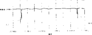
Fig. 4 is a spectrum, shows the response spectrum of double resonance superconductor detector among Fig. 1;
Fig. 5 is a process flow diagram, shows the frequency step of many resonance detectors in the construction drawing 1;
Fig. 6 shows the sandwich construction of multiple resonance superconducting probe;
Fig. 7 is a process flow diagram, shows the step of the many resonance detectors of multilayer in the construction drawing 6;
Fig. 8 shows the rectangular configuration of the receiving coil that is used for multiple resonance superconducting probe;
Fig. 9 shows the structure of the another kind of receiving coil that uses in multiple resonance superconducting probe.
The description of preferred embodiment
Multiple resonance superconducting probe will improve the quality of magnetic resonance image (MRI), perhaps promote to utilize other application of reading many resonant frequencies gained data.A plurality of resonance coils are placed in the single detector, so that utilize two or more different atomic nucleus to check the same area simultaneously.Can use the accurate position of determining detector from a nuclear information, and information nuclear from another, that have low resolution is used for analyzing, the information itself that resolution is lower may not be determined position of detector.
Preferred embodiment as described herein is the double resonance detector that is used for MRI.But, the invention is not restricted to two receiving coils, it can also comprise three or more receiving coil with the technical construction of following same principle.In addition, many resonance detectors are not limited to MRI described herein and use, and it can also survey a plurality of frequencies in a certain frequency spectrum for any purpose.
Use
1H and
23The multiple resonance superconducting probe of Na produces the MRI image and can set up
1The high-resolution anatomic image of H and
23Being correlated with between Na distributes.In addition, merge
1H and
23The MRI of Na provides side information, can describe better by the tissue of imaging.
Here the probe designs of describing as first preferred embodiment is made up of two discrete coaxial coils, and these two coils are positioned on the same substrate, and the frequency tuning of each coil is arrived
23Na or
1The resonant frequency of H.The challenge relevant with this superconduction double resonance probe designs is the coupling of calculating between the coil, so that calculate mutual inductance.Impedance in mutual inductance and the resonant circuit effectively is coupled, and makes resonant frequency generation frequency displacement.By determining coupling coefficient, can obtain the resonant frequency after the coil frequency displacement.Correspondingly, known coupling coefficient, suitable resonant frequency that can calculating detector is so that calculate correct tuning detector.If when the design coil, do not consider mutual impedance, can cause detector not resonate so.
Fig. 1 shows the planimetric map according to the multiple resonance superconducting probe of the present invention's structure.Although should example only show two discrete receiving coils, also can center on placement with one heart with being used to receive the interpole coil that adds resonant frequency, or in the coil shown in being placed on.As shown in the figure, superconductor detector 100 has two coils, and 103, two coils of promptly external take-up circle 101 and interior receiving coil all are positioned on the substrate 120.Each coil is by such as Y
1Ba
2Cu
3O
7-xMake Deng superconductor.Exterior loop 101 has a spiral coil 105 and a plurality of " interdigital ", and interdigital is the extension of superconductor.Among the figure illustration interdigital 107 and 109.Spiral coil part provides inductance for receiving coil, and interweave mutually interdigital for receiving coil provides necessary electric capacity so that tuning its resonant frequency.The resonant frequency of coil is directly relevant with the inductance and the electric capacity of structure.The electric capacity of coil 101 interdigital number direct and in the coil is relevant.Interior loop 103 also has a spiral coil 111 and a plurality of link to each other with spiral coil 111 interdigital, for example interdigital 113.Substrate 120 can be the plane, or flexible, so that it is crooked or be wrapped in by on the imaging object.
When carrying out magnetic resonance imaging, each receiving coil detects the different frequency that is produced by magnetized atomic nucleus.The structure of Fig. 1 detector detects with interior receiving coil
1H detects with external take-up circle
23Na.All coils are placed on the mutual visual field that can improve two receiving coils on the substrate with one heart, can reduce the mutual inductance between the coil simultaneously.
All receiving coils among Fig. 1 can be used Y
1Ba
2Cu
3O
7-x(YBCO) superconducting thin film is made, and is positioned at single crystal LaAlO
3On the substrate, and can use the active ion implantation technique, perhaps dried or wet etch techniques is made figure.Detector comprises two discrete coaxial coils, and coil is positioned on the same substrate, and size be in the magnetic field of 3T be tuned to
23Na and
1The Larmor frequency of H, described frequency correspond respectively to 33.77 MHz and 127.71 MHz.As mentioned above, each receiving coil comprises single toroidal inductor, intersects interdigital capacitor between the annular ring of inductor.For this routine exterior loop, the line width of inductor is 275 microns, is 33 microns and intersect interdigital width, and spacing is 22 microns.For this routine interior loop, the line width of inductor is 139 microns, is 90 microns and intersect interdigital width, and spacing is 60 microns.The higher resonance coil (exterior loop) of frequency have 100-200 to about interdigital, and the lower resonance coil (interior loop) of frequency have 500-600 to about interdigital.The invention is not restricted to described concrete size, but size will change according to the mutual inductance of required FOV, expection and with the resonant frequency that detects.
Select the size of coil, the following target of balance: significant SNR gain factor, more weak coupling between enough big visual field and the resonance body.In this example, the exterior loop diameter is for being respectively 2.44 centimetres and 1.39 centimetres with the interior loop diameter.The mutual inductance meeting of two coils changes the resonant frequency of each coil.In order to survey institute's selected frequency of certain specific atoms nuclei, coil design must be considered mutual inductance.
Fig. 2 A and 2B are curve maps, show the funtcional relationship between the coupling coefficient between the resonant frequency of multiple resonance superconducting coil shown in Figure 1 and two receiving coils.When coil was close, coupling coefficient increased to 1.Fig. 2 A represents that when coil was close, the resonant frequency of exterior loop 101 sharply increased.Fig. 2 B represents that when coil was close, the resonant frequency of interior loop 103 sharply reduced.During as each coil of a detector part, must calculate this resonance frequency shift effect in final design.
Corrective action and method to the mutual inductance of two receiving coils will be described now.Below analyze three or more receiving coil that also is applicable in the same detector.Two very approaching resonance bodies will make its magnetic field coupling separately.This magnetic field coupling between the resonance body can be described with the mutual inductance (M) that following formula provides:
Wherein k is a coupling coefficient, L
11Be the elementary self-induction of first receiving coil, and L
22It is the secondary self-induction of second receiving coil.As shown in Figure 3, can simulate the resonance coil of two couplings with two simple circuit.Each circuit of Fig. 3 all comprises capacitor connected in series, resistor and inductor, each circuit inductance device coupling.
Fig. 3 shows first circuit 301, and this circuit comprises capacitor C1 303, and capacitor C1 303 is connected in series with resistor R 1 305, and resistor R 1 305 is connected in series with inductor L1 307.Second circuit 309 be placed on first circuit 301 near, it comprises capacitor 311, this capacitor and resistor 313 are connected in series, and resistor 313 is connected in series with inductor 315, inductor links to each other with capacitor 311, forms a complete circuit.As seen from the figure, the existence of secondary coupled circuit 309 has increased equiva lent impedance (ω M) for primary circuit 301
2/ Z
sThereby primary circuit will move resonant frequency according to mutual inductance.Equally, first circuit 301 also can influence the resonant frequency of second circuit 309.When coupling coefficient can be ignored, mutual impedance was corresponding less, and primary circuit is identical when almost not existing with secondary circuit.Will there be two peaks in frequency spectrum at two centre frequency places that are scheduled to.When coupling coefficient increased, the lower resonance body of frequency was to downshift, and the higher resonance body of frequency is to upshift.In order to design the double resonance detector, it is resonated with correct frequency, must consider the mutual inductance between the coil.This needs two steps: determine coupling coefficient, and derive the detector resonant frequency as coupling function.
The size of coil, geometric configuration and their relative position have determined coupling coefficient.In order to calculate coupling, coil is modeled to two conductor loops, its radius is respectively a and b, and parallel shafts is at a distance of c, and the plane is at a distance of d.The general type of the mutual inductance between these two conductor loops is expressed from the next:
Wherein μ is a magnetic permeability, J1 (Ka), and J1 (Kb), J0 (Kc) is the Bessel function on first and second rank, and K is expressed from the next:
For situation considered here, because ring is coaxial and coplanar, so for Fig. 1 structure, c=0 and d=0.The self-induction L of conductor loop
11And L
22Can calculate with following formula:
Wherein r is the radius of lead.In wushu (2) and (4) substitution formula (1) afterwards, obtain coupling coefficient.Coupling between the conductor loop increases with approaching 1 than b/a.Therefore, when two coils moved to such an extent that be close together, coupling increased.In order to make coupling minimum, should make the ratio of b/a as much as possible little, therefore coil to be put at a distance of far away as much as possible.But, ratio can only be reduced to certain a bit, after this point, the use of detector can weaken, and is unavailable because field of view (FOV) is varied down to.
The impedance of primary circuit 301 and secondary circuit 309 is made up of active component and reaction component among Fig. 3, and they can be write as respectively:
R wherein
1305 and R
2The 313rd, resistance, L
1307 and L
2The 315th, inductance, C
1303 and C
2The 313rd, electric capacity, and X
1And X
2Be defined as total reactance of each circuit.By to circuit application Kirchoff law, can obtain the electric current I in the secondary circuit
2The absolute value of secondary current can be represented with following formula:
When denominator hour, secondary current is with maximum.With regard to denominator to X
2Differentiate, when following formula is set up, I
2With maximum.
Can find similar statement formula for primary circuit.The following relation of definition:
And with X
1And X
2Value substitution formula (7) in, provide:
Wherein the root of f is the resonant frequency of detector after the consideration mutual inductance, and f
1And f
2It is the resonant frequency of coil when being coupled as zero.The quality factor of hypothesis primary resonance body is higher when obtaining equation (9), so that 1/Q
1 2Can ignore, for superconduction resonance body, this is not irrational.The root of f is ± f
1' and ± f
2' form, and provide by following equation:
Equation (10) allows according to coupling coefficient and f
1And f
2Value come resonant frequency behind the calculating frequency shift.If the coupling of two coils can be ignored, equation (10) is reduced to f so
1'=f
2And f
2'=f
2As for must be how little, then depend on f in order to ignore the k value
1And f
2Relative value.Fig. 2 A and 2B are for f
1=33.77 MHz, f
2(they correspond respectively to=127.71MHz
23Na and
1The resonant frequency of H) time, as the f of the function of coupling
1' and f
2' curve map.These two graphical representation, coupling be resonance body that frequency is lower to downshift, the resonance body that frequency is higher is to upshift.As a result, the coil that suitably is tuned at zero coupling place will not resonate for the situation of k>0.For a specific coupling coefficient, determine suitable f with correct tuning detector
1And f
2Value is useful.Ask f with regard to equation (9)
1And f
2Separate:
By giving the f in the equation (11)
1' and f
2' assignment makes it equal the suitable resonant frequency of detector, just can determine f
1And f
2
For the detector with the described size of Fig. 1, the corresponding b/a ratio of two coils is 0.6, this means that from equation (1) to (4), coupling coefficient is approximately 0.15.By with regard to k=0.2, and f
1'=33.77 MHz and f
2The situation of '=127.71 MHz is found the solution equation (11), coil design should be become at f
1=33.82 MHz and f
2The resonance of=129.93 MHz places is so that detector resonates.For the b/a ratio of selecting in this example, frequency displacement is only very important to the higher resonance body of frequency.
Fig. 4 shows the response spectrum of double resonance superconductor detector as shown in Figure 1.Frequency spectrum comprises two peaks 401 and 403, and they correspond respectively to
23Na and
1The frequency of H.Two peak positions are in it is designed the hundreds of KHz of resonant frequency.Experiment finds that coupling coefficient is 0.2, and it and calculated value 0.15 have rational consistance.For
23Na and
1H, the unloaded Q that records coil respectively is 7.9 * 10
3With 11.7 * 10
3
Measure multiple resonance superconducting probe with Hewlett-Packard 8712B network analyzer.Under about 30K temperature, in the normal flow cryostat, measure detector.Concentric cable with inductive couplings carries out reflection measurement, thereby determines the response and the quality factor (Q) of detector.Phantom is carried out (2-D) Fourier imaging of bidimensional, and obtain
23Na and
1The H image.
Compare with traditional magnet ring shape detector, multiple resonance superconducting probe has three tangible advantages at least: higher SNR; Can be effectively with the relative zone location of being concerned about of detector, and can obtain the same area of being concerned about
1H and
23The Na image, and side information is provided, cause better tissue to be described.In addition, probe designs goes for such as other atomic nucleus such as potassium, carbon, nitrogen and fluorine.
Fig. 5 is a process flow diagram, shows the step of making many resonant frequencies superconductor detector shown in Figure 1.These steps are easy to be modified as the superconductor detector that making is used to survey three or more resonant frequency.
Then, step 505 forms coil pattern on superconducting thin film.The design coil pattern so that tuning coil (length of spiral in ductor) and electric capacity (in the coil interdigital number), is obtained roughly and is designed the resonant frequency that equates.Design consideration is to the consideration of following factor: more weak coupling between significant SNR gain factor (requiring less coil), bigger FOV (requiring bigger coil) and the coil.The above-mentioned model of design utilization has been considered any mutual inductance between the coil.
For example, be used for or wet etch techniques or ion transplanting technology are finished coil manufacturing process.In wet etching process, mask is placed on the superconducting thin film part that will keep, then film is placed in the chemical bath, never remove superconductor on the substrate of mask.When using dry etching process (for example, ion-milling), equally mask is placed on constituting on the superconducting thin film part of receiving coil, with ion directive film, remove a part of superconductor then, and only stay the superconducting thin film under the mask.In ion implantation technology, (such as Si, B, Al etc.) inject a part of HTS material by mask with active ion, and wherein mask covers on the superconducting layer by the shape of required loop construction.With 20-200KeV specific energy and 10
14-10
17/ centimetre
2Dosage inject ion so that implant part is transferred in the insulator, and make not implant part superconduction.The result of these technologies obtains the desired structure of superconducting thin film, such as the structure among Fig. 1.
Then, if necessary, step 507 with many receiving coils fine tuning to suitable resonant frequency, so that take into account small out of true in any tolerance limit in the manufacture process or the design.Carry out tuningly with the following methods, promptly remove some interdigitally,, thereby change resonant frequency so that change coil capacitance from each receiving coil.After to the coil fine tuning, each coil will have suitable resonant frequency, so that detect the nuclear frequency of resonance of surveying them and will receiving.
Fig. 6 shows second preferred embodiment of multiple resonance superconducting probe.In Fig. 6, receiving coil is overlayed on the substrate discretely with film.Rhythmo structure is different from all receiving coils and puts at grade with one heart.Fig. 6 shows the multiple resonance superconducting probe 601 of multilayer, and this detector has substrate layer 603, first coil layer 605, cushion 607 and second coil layer 609.Although only drawn two receiving coils in this example, the present invention can use three or more receiving coil according to the present invention's structure.This rhythmo structure allows two coils to have identical or similar size, and still can survey two different frequencies.Fig. 6 illustrates, and the coil diameter of the first receiving coil layer 605 is D
1, the diameter D of this diameter and second receiving coil
2Equate.Remove from receiving coil with laser beam or additive method some interdigital, thereby change electric capacity still to changing resonant frequency.In this way can be after manufacturing the resonant frequency of tuning each coil layer.Have same diameter and spatially overlapping two or more receiving coils and also will have identical visual field, this can improve the detection area of detector.In addition, in fact the structure of overlapping layer being separated with a cushion can eliminate the mutual inductance between receiving coil.
The width of substrate 603 is generally between 0.5 millimeter and 1 millimeter.Cement line ring layer 605 on substrate, its width are generally between 0.1 micron and 0.5 micron.Next, deposition one cushion 607 on first coil layer is not so that two adjacent coil layer can contact and be short-circuited.In addition, cushion can reduce any mutual inductance effect.The thickness of cushion is generally 0.2 to 2 micron.At last, deposit second coil layer 609 at the top of cushion, and it is aimed at first coil layer 605.The thickness of second coil layer is generally 0.1 micron to 0.5 micron.According to the present invention, also can use other thickness.
On the coil layer top, put an additional cushion layer, and on the top of additional cushion layer, put an additional wire ring layer, be easy on sandwich construction, increase additional coil layer thus.Each coil layer will detect different resonant frequencies, to improve image quality.
Fig. 7 shows and makes the step of multilayer multiple resonance superconducting probe as shown in Figure 6.Be easy to increase the additional step of making multi-layer detector, so that form detector with three or more resonance receiving coil.
Then, step 705 forms the pattern of single receiving coil in superconducting thin film.The design coil pattern so that tuning coil (length of spiral in ductor) and electric capacity (in the coil interdigital number), is obtained roughly and is designed the resonant frequency that equates.Design consideration is to the consideration of following factor: more weak coupling between significant SNR gain factor (requiring less coil), bigger FOV (requiring bigger coil) and the coil.The above-mentioned model of design utilization has been considered any mutual inductance between the coil.
Can finish this manufacturing process with ion transplanting technology.Mask is covered and will form on the superconductor of receiving coil.Then, make the superconductor of its contact lose superconductivity with ion transplanting technology, and become insulation.But for receiving coil part and insulated part, it is identical that the height of film keeps.This is opposite with chemical etching or ion-milling, and under one situation of back, film surface becomes inhomogeneous because of etching.Under the situation of multi-layer detector, for to next layer film of external sediment, implanted and not implanted film surface part must have same crystal structure and must be the plane.
Fig. 8 shows the structure of the another kind of receiving coil of arranging according to the present invention.Although only show two coils among this figure, according to the different frequency number that hope is surveyed, detector can comprise the coil of any number.The rectangular shape of coil produces a rectangular field, if to long narrow body part (such as, vertebra or hand fork refer to) get MRI, this is favourable.Exterior loop 801 comprises a spiral winding 802 and a plurality of fixing interdigital.Illustrate interdigital 803 and 805 for example.Interior loop 807 comprises spiral winding 808 and fixing interdigital.Illustrate interdigital 809 and 811 for example.With former described equation, can calculate mutual inductance and to the corresponding correction of mutual inductance.Width and length that can tuning detector be so that partly obtain the optimal fit factor (and visual field) to a certain given body.Can also customize other coil shape, be used for required visual field.
Fig. 9 shows the another kind of receiving coil structure that can use with the present invention.Coil 900 comprises inductive part 901 and a plurality of fixing interdigital.Illustrate interdigital 903 and 905 for example.In order to obtain planar type detector, another receiving coil in coil 900 structures can be placed in the zone that inductive part 901 determines.Another kind method is in a plurality of coil layer of above-mentioned multi-layer detector structure, to use this receiving coil.As long as comprise suitable inductive part and capacitive part, each receiving coil that uses in this invention can be used constructed in various ways, so that make receiving coil obtain required resonant frequency.
Principle of the present invention only has been described above.Therefore should be appreciated that, those skilled in the art can make various by implementing system, equipment and the method for the principle of the invention, although these systems, equipment and method do not offer some clarification on or describe at this, they are in the spirit and scope that claim of the present invention limits.
For example, can be with the part of multiple resonance superconducting probe as certain device, this device can receive radio, microwave or the cellular transmission of selected resonant frequency.
Claims (22)
1. a multiple resonance superconducting probe is characterized in that, comprising:
One substrate;
A plurality of nonoverlapping film coils, described coil stationary is on described substrate;
Wherein, each described coil is made by superconductor, and is tuned to selected different resonant frequencies.
2. detector as claimed in claim 1 is characterized in that, and is described tuning to the described mutual inductance sensitivity between described a plurality of coils.
3. detector as claimed in claim 1 is characterized in that, each described coil comprises a plurality of interdigital, and the described resonant frequency of described coil is responsive to described interdigital sum.
4. detector as claimed in claim 3 is characterized in that, described interdigital described sum is between 100 to 200.
5. detector as claimed in claim 3 is characterized in that, described interdigital described sum is between 500 to 600.
6. detector as claimed in claim 1 is characterized in that, each described coil has identical central point.
7. detector as claimed in claim 1 is characterized in that the shape of each described coil is circular.
8. detector as claimed in claim 1 is characterized in that the shape of each described coil is a rectangle.
9. detector as claimed in claim 1 is characterized in that, described detector has a visual field, and about by the imaging selection area, and described coil leaves a ultimate range and places, and still keeps acceptable described visual field for described detector.
10. detector as claimed in claim 1 is characterized in that described substrate is soft.
11. a multiple resonance superconducting probe is characterized in that, comprising:
One substrate;
At least two coil film layers to selected different resonant frequencies, comprise superconducting coil with each described coil tuning; With
One cushion, it is between adjacent described coil layer.
12. detector as claimed in claim 11 is characterized in that, described coil comprises a plurality of interdigital, and the described resonant frequency of described coil is responsive to described interdigital sum.
13. detector as claimed in claim 11 is characterized in that, each described coil has identical central point.
14. detector as claimed in claim 11 is characterized in that, being shaped as of each described coil is circular.
15. detector as claimed in claim 11 is characterized in that, the shape of each described coil is a rectangle.
16. detector as claimed in claim 11 is characterized in that, described substrate is soft.
17. a method of making multiple resonance superconducting probe is characterized in that, may further comprise the steps;
Select a substrate;
The superconducting film that deposition one approaches on described substrate;
On described film, form a plurality of ceoncentrically wound coils; And
With each described coil tuning to a resonant frequency, described tuning mutual inductance sensitivity to described a plurality of coils.
18. method as claimed in claim 17 is characterized in that, each described coil comprises many interdigital, and described method also comprises the steps: to remove the described interdigital of selected number from described coil, to change the described resonant frequency of described coil.
19. a method of making multiple resonance superconducting probe is characterized in that, may further comprise the steps;
Select a substrate;
Deposition first superconducting thin film on described substrate;
Form a coil on described film, described film roughly keeps level;
On described first superconducting thin film, deposit cushion;
Deposition second superconducting thin film on described cushion;
Form coil in described second film, described second film roughly keeps level;
With each described coil tuning to a resonant frequency, described tuning mutual inductance sensitivity to described a plurality of coils.
20. method as claimed in claim 19 is characterized in that, each described coil comprises many interdigital, and described method also comprises the steps: to remove the described interdigital of selected number from described coil, to change the described resonant frequency of described coil.
21. method as claimed in claim 19 is characterized in that, and is further comprising the steps of:
Deposition one additional cushion layer on described second thin layer;
Deposition one additional superconducting thin film on described additional cushion layer; And
Form a coil in described additional film, described film roughly keeps level.
22. method as claimed in claim 19 is characterized in that, the step of described formation coil is finished with ion transplanting technology.
Applications Claiming Priority (2)
| Application Number | Priority Date | Filing Date | Title |
|---|---|---|---|
| US3153396P | 1996-12-02 | 1996-12-02 | |
| US60/031,533 | 1996-12-02 |
Publications (1)
| Publication Number | Publication Date |
|---|---|
| CN1245562A true CN1245562A (en) | 2000-02-23 |
Family
ID=21859988
Family Applications (1)
| Application Number | Title | Priority Date | Filing Date |
|---|---|---|---|
| CN97181555A Pending CN1245562A (en) | 1996-12-02 | 1997-11-25 | Multiple resonance superconducting probe |
Country Status (11)
| Country | Link |
|---|---|
| US (1) | US6169399B1 (en) |
| EP (1) | EP0941491B1 (en) |
| JP (1) | JP2001505463A (en) |
| KR (1) | KR20000069263A (en) |
| CN (1) | CN1245562A (en) |
| AT (1) | ATE232305T1 (en) |
| AU (1) | AU5369398A (en) |
| CA (1) | CA2273150A1 (en) |
| DE (1) | DE69718929T2 (en) |
| HK (1) | HK1024747A1 (en) |
| WO (1) | WO1998025163A1 (en) |
Cited By (6)
| Publication number | Priority date | Publication date | Assignee | Title |
|---|---|---|---|---|
| CN100363754C (en) * | 2004-11-22 | 2008-01-23 | 威海双丰电子集团有限公司 | Earthquake demodulator by microelectromechanical speed |
| CN102007421A (en) * | 2008-04-11 | 2011-04-06 | 通用电气公司 | Multi-frequency RF coil |
| CN104656046A (en) * | 2004-05-03 | 2015-05-27 | 皇家飞利浦电子股份有限公司 | System and method for magnetic resonance imaging |
| CN111630785A (en) * | 2017-12-15 | 2020-09-04 | 亚历山大·曼内斯基 | Dual detector with transverse coils |
| CN114910853A (en) * | 2021-02-10 | 2022-08-16 | 清华大学 | MRI image enhancement super-structure surface array unit assembly |
| CN114910853B (en) * | 2021-02-10 | 2024-04-26 | 清华大学 | MRI image enhancement super-structure surface array unit assembly |
Families Citing this family (54)
| Publication number | Priority date | Publication date | Assignee | Title |
|---|---|---|---|---|
| US6335622B1 (en) * | 1992-08-25 | 2002-01-01 | Superconductor Technologies, Inc. | Superconducting control elements for RF antennas |
| JP2004509720A (en) * | 2000-09-26 | 2004-04-02 | コーニンクレッカ フィリップス エレクトロニクス エヌ ヴィ | Vertical magnetic field type MRI apparatus having a conical air gap located in a main magnet |
| US6489768B1 (en) | 2000-10-23 | 2002-12-03 | Varian, Inc. | Superconductive networks to optimize multiply tuned NMR coils |
| US6556013B2 (en) * | 2001-03-09 | 2003-04-29 | Bruker Biospin Corp. | Planar NMR coils with localized field-generating and capacitive elements |
| DE10118835C2 (en) * | 2001-04-17 | 2003-03-13 | Bruker Biospin Ag Faellanden | Superconducting resonators for applications in NMR |
| US6590394B2 (en) | 2001-09-28 | 2003-07-08 | Varian, Inc. | NMR probe with enhanced power handling ability |
| KR100462029B1 (en) | 2003-03-14 | 2004-12-18 | 한국전자통신연구원 | A Fiber Amplifier and A Controlling Method of the same |
| US7521932B2 (en) * | 2003-05-06 | 2009-04-21 | The Penn State Research Foundation | Method and system for adjusting the fundamental symmetric mode of coupled high temperature superconductor coils |
| US6943550B2 (en) * | 2003-05-09 | 2005-09-13 | The University Of Hong Kong | High temperature superconductor tape RF coil for magnetic resonance imaging |
| JP4090389B2 (en) * | 2003-06-10 | 2008-05-28 | 株式会社日立製作所 | Nuclear magnetic resonance apparatus |
| US6960914B2 (en) * | 2003-06-27 | 2005-11-01 | Ge Medical Systems Global Technology Company, Llc | Methods and apparatus for imaging systems |
| US20050104593A1 (en) * | 2003-08-21 | 2005-05-19 | Laubacher Daniel B. | Nuclear quadrupole resonance detection system using a high temperature superconductor self-resonant coil |
| US7295085B2 (en) * | 2003-08-21 | 2007-11-13 | E.I. Du Pont De Nemours And Company | Process for making high temperature superconductor devices each having a line oriented in a spiral fashion |
| US7148684B2 (en) * | 2003-10-23 | 2006-12-12 | E.I. Du Pont De Nemours And Company | Method for biological identification using high temperature superconductor enhanced nuclear quadrupole resonance |
| WO2005047917A1 (en) | 2003-11-12 | 2005-05-26 | E.I. Dupont De Nemours And Company | Detection of contraband using nuclear quadrupole resonance |
| US20070245374A1 (en) | 2003-11-24 | 2007-10-18 | Inventec Corporation | Video program subtitle tex recording method and system |
| US7301344B2 (en) * | 2003-11-24 | 2007-11-27 | E.I. Du Pont De Nemours & Co. | Q-damping circuit including a high temperature superconductor coil for damping a high temperature superconductor self-resonant coil in a nuclear quadrupole resonance detection system |
| US7332910B2 (en) | 2003-11-24 | 2008-02-19 | E.I. Du Pont De Nemours And Company | Frequency detection system comprising circuitry for adjusting the resonance frequency of a high temperature superconductor self-resonant coil |
| WO2005059582A1 (en) * | 2003-12-15 | 2005-06-30 | E.I. Dupont De Nemours And Company | The use of multiple sensors in a nuclear quadrupole resonance detection system to improve measurement speed |
| WO2005109023A2 (en) | 2004-02-04 | 2005-11-17 | E.I. Dupont De Nemours And Company | Nqr rf coil assembly comprising two or more coils which may be made from hts |
| WO2005078469A1 (en) | 2004-02-04 | 2005-08-25 | E.I. Dupont De Nemours And Company | The use of two or more sensors to detect different nuclear quadrupole resonance signals of a target compound |
| US7295009B2 (en) * | 2004-03-10 | 2007-11-13 | Bruker Biospin Corporation | Planar NMR coil with gyromagnetic arc suppression |
| US7248046B2 (en) * | 2004-04-15 | 2007-07-24 | E. I. Du Pont De Nemours And Company | Decoupling high temperature superconductor sensor arrays in nuclear quadrupole resonance detection systems |
| US7116535B2 (en) * | 2004-04-16 | 2006-10-03 | General Electric Company | Methods and apparatus for protecting an MR imaging system |
| US7279897B2 (en) | 2004-04-30 | 2007-10-09 | E. I. Du Pont De Nemours And Company | Scanning a band of frequencies using an array of high temperature superconductor sensors tuned to different frequencies |
| WO2006073452A2 (en) * | 2004-04-30 | 2006-07-13 | E.I. Dupont De Nemours And Company | Methods and apparatus for scanning a band of frequencies by nqr using an array of high temperature superconductor sensors |
| US7265549B2 (en) * | 2004-04-30 | 2007-09-04 | E. I. Du Pont De Nemours And Company | Scanning a band of frequencies using an array of high temperature superconductor sensors tuned to the same frequency |
| JP4653439B2 (en) * | 2004-08-10 | 2011-03-16 | ジーイー・メディカル・システムズ・グローバル・テクノロジー・カンパニー・エルエルシー | Gradient coil and MRI apparatus |
| EP1929320A2 (en) | 2004-09-16 | 2008-06-11 | Koninklijke Philips Electronics N.V. | Magnetic resonance receive coils with compact inductive components |
| US7222934B2 (en) * | 2004-11-22 | 2007-05-29 | Xerox Corporation | Method and apparatus for mounting an inkjet printhead |
| JP4647984B2 (en) * | 2004-12-02 | 2011-03-09 | 株式会社日立製作所 | Nuclear magnetic resonance probe coil |
| EP1828797A1 (en) | 2004-12-03 | 2007-09-05 | E.I. Dupont De Nemours And Company | Decoupling of excitation and receive coils of an nqr detection system during signal reception |
| JP4593255B2 (en) * | 2004-12-08 | 2010-12-08 | 株式会社日立製作所 | NMR apparatus and probe for NMR measurement |
| EP1831714A1 (en) * | 2004-12-13 | 2007-09-12 | E.I. Dupont De Nemours And Company | Metal shield alarm in a nuclear quadrupole resonance/x-ray contraband detection system |
| US8334692B2 (en) | 2005-06-24 | 2012-12-18 | Koninklijke Philips Electronics N.V. | Simultaneous multinuclear magnetic resonance imaging |
| JP5006542B2 (en) * | 2005-12-26 | 2012-08-22 | 株式会社日立製作所 | NMR apparatus and probe for NMR measurement |
| US20070262776A1 (en) * | 2006-05-10 | 2007-11-15 | Petropoulos Labros S | Magnetic Resonance Imaging Magnet Assembly System with Improved Homogeneity |
| JP4971685B2 (en) * | 2006-05-25 | 2012-07-11 | 株式会社日立製作所 | Nuclear magnetic resonance probe coil |
| DE102006053472B4 (en) * | 2006-11-14 | 2009-12-10 | Bruker Biospin Ag | Method for producing a tuned RF resonator system |
| RU2491568C2 (en) * | 2007-02-26 | 2013-08-27 | Конинклейке Филипс Электроникс, Н.В. | Double-resonant radio frequency strong field surface coils for magnetic resonance |
| US8731635B2 (en) * | 2007-11-07 | 2014-05-20 | University of Pittsburgh—of the Commonwealth System of Higher Education | Coils for magnetic resonance spectroscopy and imaging of human breast |
| US8175679B2 (en) | 2007-12-26 | 2012-05-08 | St. Jude Medical, Atrial Fibrillation Division, Inc. | Catheter electrode that can simultaneously emit electrical energy and facilitate visualization by magnetic resonance imaging |
| US20100315087A1 (en) * | 2008-02-12 | 2010-12-16 | The Board Of Trustees Of University Of Illinois | Apparatus and method of magnetic resonance imaging |
| KR20100058894A (en) * | 2008-11-25 | 2010-06-04 | 한국전자통신연구원 | Wearable magnetic resonator for mri resolution improvement, and application device of the same magnetic resonator |
| WO2011035333A1 (en) * | 2009-09-21 | 2011-03-24 | Time Medical Holdings Company Limited | Superconductor rf coil array |
| US8410781B1 (en) * | 2010-06-28 | 2013-04-02 | Hong Kong Applied Science And Technology Research Institute Co., Ltd. | High temperature superconductor receiver coil magnetic resonance imaging systems and methods compatible with an infant incubator |
| US8564294B2 (en) * | 2011-06-28 | 2013-10-22 | Agilent Technologies, Inc. | Nuclear magnetic resonance probe comprising slit superconducting coil with normal-metal overlayer |
| US8779768B2 (en) * | 2012-06-12 | 2014-07-15 | The Florida State University Research Foundation, Inc. | NMR RF probe coil exhibiting double resonance |
| CN102707249A (en) * | 2012-07-03 | 2012-10-03 | 汤丽萍 | Radio frequency coil of nuclear magnetic resonance imaging device |
| CN106802358B (en) * | 2015-11-26 | 2023-06-30 | 云南电网有限责任公司瑞丽供电局 | Easy-to-detach radio frequency coil device for detecting composite insulator |
| JP6735619B2 (en) | 2016-07-20 | 2020-08-05 | 日本電子株式会社 | Method for manufacturing detection coil for magnetic resonance measurement |
| KR101806198B1 (en) | 2016-12-30 | 2017-12-08 | 연세대학교 산학협력단 | Radiofrequency coil and medicla imaging apparatus using the same |
| KR102276110B1 (en) * | 2019-11-06 | 2021-07-13 | 가천대학교 산학협력단 | RF coil for UHF MRI system |
| WO2022232416A1 (en) * | 2021-04-29 | 2022-11-03 | Cornell University | Self-tuning liquid metal rf coil and coil array for mri |
Family Cites Families (11)
| Publication number | Priority date | Publication date | Assignee | Title |
|---|---|---|---|---|
| US4446431A (en) | 1981-08-24 | 1984-05-01 | Monsanto Company | Double-tuned single coil probe for nuclear magnetic resonance spectrometer |
| US4636730A (en) * | 1984-08-16 | 1987-01-13 | General Electric Company | NMR spectroscopy body probes with at least one surface coil |
| EP0299325B1 (en) | 1987-07-17 | 1991-12-18 | Siemens Aktiengesellschaft | Actively shielded supraconducting magnet of a nuclear spin tomographic apparatus |
| US5280248A (en) | 1992-07-24 | 1994-01-18 | Picker International, Inc. | Biplanar RF coil for magnetic resonance imaging systems |
| DE69023403T2 (en) | 1989-07-21 | 1996-07-11 | Hitachi Ltd | Aluminum stabilized superconductor and superconducting coil and method for producing the superconductor. |
| US6335622B1 (en) * | 1992-08-25 | 2002-01-01 | Superconductor Technologies, Inc. | Superconducting control elements for RF antennas |
| US5276389A (en) * | 1991-12-14 | 1994-01-04 | Leopold Kostal Gmbh & Co. Kg | Method of controlling a windshield wiper system |
| US5351007A (en) | 1992-06-01 | 1994-09-27 | Conductus, Inc. | Superconducting magnetic resonance probe coil |
| US5276398A (en) | 1992-06-01 | 1994-01-04 | Conductus, Inc. | Superconducting magnetic resonance probe coil |
| US5565778A (en) * | 1992-06-01 | 1996-10-15 | Conductus, Inc. | Nuclear magnetic resonance probe coil |
| US5585723A (en) * | 1995-03-23 | 1996-12-17 | Conductus, Inc. | Inductively coupled superconducting coil assembly |
-
1997
- 1997-11-25 CA CA002273150A patent/CA2273150A1/en not_active Abandoned
- 1997-11-25 WO PCT/US1997/022080 patent/WO1998025163A1/en not_active Application Discontinuation
- 1997-11-25 JP JP52575498A patent/JP2001505463A/en not_active Abandoned
- 1997-11-25 EP EP97950785A patent/EP0941491B1/en not_active Expired - Lifetime
- 1997-11-25 AU AU53693/98A patent/AU5369398A/en not_active Abandoned
- 1997-11-25 DE DE69718929T patent/DE69718929T2/en not_active Expired - Fee Related
- 1997-11-25 KR KR1019997004878A patent/KR20000069263A/en not_active Application Discontinuation
- 1997-11-25 CN CN97181555A patent/CN1245562A/en active Pending
- 1997-11-25 AT AT97950785T patent/ATE232305T1/en not_active IP Right Cessation
- 1997-12-01 US US08/982,164 patent/US6169399B1/en not_active Expired - Lifetime
-
2000
- 2000-03-15 HK HK00101578A patent/HK1024747A1/en not_active IP Right Cessation
Cited By (8)
| Publication number | Priority date | Publication date | Assignee | Title |
|---|---|---|---|---|
| CN104656046A (en) * | 2004-05-03 | 2015-05-27 | 皇家飞利浦电子股份有限公司 | System and method for magnetic resonance imaging |
| CN100363754C (en) * | 2004-11-22 | 2008-01-23 | 威海双丰电子集团有限公司 | Earthquake demodulator by microelectromechanical speed |
| CN102007421A (en) * | 2008-04-11 | 2011-04-06 | 通用电气公司 | Multi-frequency RF coil |
| CN102007421B (en) * | 2008-04-11 | 2014-09-24 | 通用电气公司 | Multi-frequency RF coil |
| CN111630785A (en) * | 2017-12-15 | 2020-09-04 | 亚历山大·曼内斯基 | Dual detector with transverse coils |
| CN111630785B (en) * | 2017-12-15 | 2021-09-24 | 亚历山大·曼内斯基 | Dual detector with transverse coils |
| CN114910853A (en) * | 2021-02-10 | 2022-08-16 | 清华大学 | MRI image enhancement super-structure surface array unit assembly |
| CN114910853B (en) * | 2021-02-10 | 2024-04-26 | 清华大学 | MRI image enhancement super-structure surface array unit assembly |
Also Published As
| Publication number | Publication date |
|---|---|
| CA2273150A1 (en) | 1998-06-11 |
| DE69718929D1 (en) | 2003-03-13 |
| WO1998025163A1 (en) | 1998-06-11 |
| HK1024747A1 (en) | 2000-10-20 |
| KR20000069263A (en) | 2000-11-25 |
| US6169399B1 (en) | 2001-01-02 |
| AU5369398A (en) | 1998-06-29 |
| EP0941491B1 (en) | 2003-02-05 |
| EP0941491A1 (en) | 1999-09-15 |
| JP2001505463A (en) | 2001-04-24 |
| EP0941491A4 (en) | 2001-05-09 |
| ATE232305T1 (en) | 2003-02-15 |
| DE69718929T2 (en) | 2003-12-04 |
Similar Documents
| Publication | Publication Date | Title |
|---|---|---|
| CN1245562A (en) | Multiple resonance superconducting probe | |
| US7859264B2 (en) | Superconducting loop, saddle and birdcage MRI coils capable of simultaneously imaging small nonhuman animals | |
| US8035382B2 (en) | Coil decoupling in magnetic resonance imaging | |
| US20060017440A1 (en) | Resonator system | |
| US7511497B2 (en) | Superconducting array of surface MRI probes | |
| JP2004511278A (en) | Method and apparatus for magnetic resonance imaging and spectroscopy using microstrip transmission line coils | |
| EP1581818A2 (en) | Degenerate birdcage coil and transmit/receive apparatus and method for same | |
| US20150369886A1 (en) | System and method for decoupling magnetic resonance imaging radio frequency coils with a modular magnetic wall | |
| EP1004885A2 (en) | Quadrature RF surface coil for magnetic resonance imaging | |
| WO2014109757A1 (en) | System and method for decoupling magnetic resonance imaging radio frequency coils with a modular magnetic wall | |
| JP2004502477A (en) | Materials with magnetic permeability at radio frequencies | |
| WO2000070356A1 (en) | Magnetically equivalent rf coil arrays | |
| US8766636B2 (en) | MRI short coils | |
| DE4218635C2 (en) | Radio-frequency receiving antenna of a device for magnetic resonance imaging with at least one capacitor | |
| JPH01299542A (en) | Inspecting device using nuclear magnetic resonance | |
| US6452393B1 (en) | Nuclear magnetic resonance birdcage coil with Cassinian oval former | |
| US7521932B2 (en) | Method and system for adjusting the fundamental symmetric mode of coupled high temperature superconductor coils | |
| JP2000507351A (en) | Arrangement for coupling rf-SQUID magnetometer to superconducting tank resonance circuit | |
| Zhurbenko et al. | Flexible self-resonant detector coil for magnetic resonance imaging of Carbon-13 | |
| US5109198A (en) | Nuclear magnetic resonance imaging apparatus | |
| Cao et al. | Equivalent capacitance model of segmented induction coil in electromagnetic exploration system for deep resources | |
| Izumizaki et al. | A High Sensitive and Low Parasitic Capacitance Folding Micro Coil with Multilayered Zigzag Diameter Wiring | |
| Nikulin et al. | Dual-tuned birdcage-like coil based on metasurfaces | |
| WO2023186611A1 (en) | A radio frequency (rf) assembly with planar resonator | |
| Wosik et al. | Superconducting 200 MHz phased array for parallel imaging |
Legal Events
| Date | Code | Title | Description |
|---|---|---|---|
| C06 | Publication | ||
| PB01 | Publication | ||
| C10 | Entry into substantive examination | ||
| SE01 | Entry into force of request for substantive examination | ||
| C02 | Deemed withdrawal of patent application after publication (patent law 2001) | ||
| WD01 | Invention patent application deemed withdrawn after publication |