CN1257645C - Image signal processor - Google Patents
Image signal processor Download PDFInfo
- Publication number
- CN1257645C CN1257645C CNB031362346A CN03136234A CN1257645C CN 1257645 C CN1257645 C CN 1257645C CN B031362346 A CNB031362346 A CN B031362346A CN 03136234 A CN03136234 A CN 03136234A CN 1257645 C CN1257645 C CN 1257645C
- Authority
- CN
- China
- Prior art keywords
- signal
- image signal
- progressive video
- interlaced image
- video signal
- Prior art date
- Legal status (The legal status is an assumption and is not a legal conclusion. Google has not performed a legal analysis and makes no representation as to the accuracy of the status listed.)
- Expired - Fee Related
Links
Images


Classifications
-
- H—ELECTRICITY
- H04—ELECTRIC COMMUNICATION TECHNIQUE
- H04N—PICTORIAL COMMUNICATION, e.g. TELEVISION
- H04N7/00—Television systems
- H04N7/01—Conversion of standards, e.g. involving analogue television standards or digital television standards processed at pixel level
-
- H—ELECTRICITY
- H04—ELECTRIC COMMUNICATION TECHNIQUE
- H04N—PICTORIAL COMMUNICATION, e.g. TELEVISION
- H04N5/00—Details of television systems
- H04N5/44—Receiver circuitry for the reception of television signals according to analogue transmission standards
- H04N5/445—Receiver circuitry for the reception of television signals according to analogue transmission standards for displaying additional information
- H04N5/44504—Circuit details of the additional information generator, e.g. details of the character or graphics signal generator, overlay mixing circuits
-
- H—ELECTRICITY
- H04—ELECTRIC COMMUNICATION TECHNIQUE
- H04N—PICTORIAL COMMUNICATION, e.g. TELEVISION
- H04N21/00—Selective content distribution, e.g. interactive television or video on demand [VOD]
- H04N21/40—Client devices specifically adapted for the reception of or interaction with content, e.g. set-top-box [STB]; Operations thereof
- H04N21/43—Processing of content or additional data, e.g. demultiplexing additional data from a digital video stream; Elementary client operations, e.g. monitoring of home network or synchronising decoder's clock; Client middleware
- H04N21/431—Generation of visual interfaces for content selection or interaction; Content or additional data rendering
- H04N21/4312—Generation of visual interfaces for content selection or interaction; Content or additional data rendering involving specific graphical features, e.g. screen layout, special fonts or colors, blinking icons, highlights or animations
- H04N21/4316—Generation of visual interfaces for content selection or interaction; Content or additional data rendering involving specific graphical features, e.g. screen layout, special fonts or colors, blinking icons, highlights or animations for displaying supplemental content in a region of the screen, e.g. an advertisement in a separate window
-
- H—ELECTRICITY
- H04—ELECTRIC COMMUNICATION TECHNIQUE
- H04N—PICTORIAL COMMUNICATION, e.g. TELEVISION
- H04N21/00—Selective content distribution, e.g. interactive television or video on demand [VOD]
- H04N21/40—Client devices specifically adapted for the reception of or interaction with content, e.g. set-top-box [STB]; Operations thereof
- H04N21/43—Processing of content or additional data, e.g. demultiplexing additional data from a digital video stream; Elementary client operations, e.g. monitoring of home network or synchronising decoder's clock; Client middleware
- H04N21/44—Processing of video elementary streams, e.g. splicing a video clip retrieved from local storage with an incoming video stream, rendering scenes according to MPEG-4 scene graphs
- H04N21/4402—Processing of video elementary streams, e.g. splicing a video clip retrieved from local storage with an incoming video stream, rendering scenes according to MPEG-4 scene graphs involving reformatting operations of video signals for household redistribution, storage or real-time display
- H04N21/440218—Processing of video elementary streams, e.g. splicing a video clip retrieved from local storage with an incoming video stream, rendering scenes according to MPEG-4 scene graphs involving reformatting operations of video signals for household redistribution, storage or real-time display by transcoding between formats or standards, e.g. from MPEG-2 to MPEG-4
-
- H—ELECTRICITY
- H04—ELECTRIC COMMUNICATION TECHNIQUE
- H04N—PICTORIAL COMMUNICATION, e.g. TELEVISION
- H04N21/00—Selective content distribution, e.g. interactive television or video on demand [VOD]
- H04N21/40—Client devices specifically adapted for the reception of or interaction with content, e.g. set-top-box [STB]; Operations thereof
- H04N21/45—Management operations performed by the client for facilitating the reception of or the interaction with the content or administrating data related to the end-user or to the client device itself, e.g. learning user preferences for recommending movies, resolving scheduling conflicts
- H04N21/462—Content or additional data management, e.g. creating a master electronic program guide from data received from the Internet and a Head-end, controlling the complexity of a video stream by scaling the resolution or bit-rate based on the client capabilities
- H04N21/4622—Retrieving content or additional data from different sources, e.g. from a broadcast channel and the Internet
-
- H—ELECTRICITY
- H04—ELECTRIC COMMUNICATION TECHNIQUE
- H04N—PICTORIAL COMMUNICATION, e.g. TELEVISION
- H04N7/00—Television systems
- H04N7/01—Conversion of standards, e.g. involving analogue television standards or digital television standards processed at pixel level
- H04N7/0117—Conversion of standards, e.g. involving analogue television standards or digital television standards processed at pixel level involving conversion of the spatial resolution of the incoming video signal
- H04N7/012—Conversion between an interlaced and a progressive signal
-
- H—ELECTRICITY
- H04—ELECTRIC COMMUNICATION TECHNIQUE
- H04N—PICTORIAL COMMUNICATION, e.g. TELEVISION
- H04N5/00—Details of television systems
- H04N5/44—Receiver circuitry for the reception of television signals according to analogue transmission standards
- H04N5/445—Receiver circuitry for the reception of television signals according to analogue transmission standards for displaying additional information
- H04N5/45—Picture in picture, e.g. displaying simultaneously another television channel in a region of the screen
Abstract
A video signal processing device of the invention includes an IP conversion means for converting an interlaced video signal that has been input into a progressive video signal and outputting it, a synthesis means for synthesizing the progressive video signal and a sub-picture or OSD that has been input and outputting the result as a progressive video signal, and a PI conversion means for converting the progressive video signal into an interlaced video signal and outputting it. The progressive video signal and the interlaced video signal are both output. Thus, the picture quality of synthetic sub-pictures or OSDs is not deteriorated and the progressive video signal and the interlaced video signal can be output simultaneously.
Description
Technical field
The present invention relates to image signal processing apparatus that the picture signal of the picture signal of row-by-row system and interlace mode is exported simultaneously.
Background technology
Up to the present, known have an image signal processing apparatus shown in Figure 7.It is so a kind of device: sprite (subpicture: be designated hereinafter simply as " sprite "), the screen display (being designated hereinafter simply as " OSD ") with dvd standard is synthesized in the picture signal of interlace mode earlier, again interlaced image signal is transformed to progressive video signal, then the picture signal of row-by-row system and the picture signal of interlace mode is exported simultaneously.
Fig. 7 is for showing the figure of existing image signal processing apparatus.
Image signal processing apparatus shown in Figure 7, comprise: the input terminal 101 of the interlaced image signal of interlace mode, the input terminal 102 that shows the signal of sprite or OSD, will be from the interlaced image signal of input terminal 101 input and the synthetic portion 103 that combines from the signal of the demonstration sprite of input terminal 102 inputs or OSD, to be transformed into the IP transformation component 104 of the progressive video signal of row-by-row system from the synthesized image signal of the interlace mode of synthetic portion 103 outputs, will be from the lead-out terminal 105 of the progressive video signal output of the row-by-row system of IP conversion 104 and will be from the lead-out terminal 106 of the synthesized image signal output of synthetic portion 103.
Secondly, the working condition of image signal processing apparatus shown in Figure 7 is described.
Synthetic portion 103, being synthesized together from the interlaced image signal of input terminal 101 input with from the sprite of the demonstration interlace mode of input terminal 102 inputs or the signal of OSD, and with this synthesized image signal output, synthesized image signal is used as the picture signal of interlace mode from lead-out terminal 106 outputs, also have, the synthesized image signal of exporting from synthetic portion 103 is imported into the IP transformation component 104.IP transformation component 104 is transformed to the synthesized image signal of interlace mode by inserting scan line the progressive video signal of row-by-row system, and from lead-out terminal 105 progressive video signal is exported.
Yet, as mentioned above, because be after the signal that will show sprite or OSD is synthesized in the picture signal of interlace mode, again it is transformed to the picture signal of row-by-row system, so the image of sprite or OSD can be unclear owing to inserted scan line.The result causes image quality decrease.
Besides, as mentioned above, be the picture signal of synthetic interlace mode under interlace mode and sprite.The display line of expression sprite number is managed by the row in the frame, when under interlace mode, synthesizing, and just must be with the row number that is transformed into for capable number in the field.This will cause circuit scale to increase.
Besides, as mentioned above, when using a plurality of field data that the image signal transformation of interlace mode is become the picture signal of row-by-row system in IP transformation component 104, being accompanied by that the conversion meeting occurs with the field is the delay of unit.It is poor that this will cause at generation time from the output of the picture signal of the row-by-row system of lead-out terminal 105 and between from the output of the picture signal of the interlace mode of lead-out terminal 106.
Summary of the invention
One object of the present invention is: a kind of image signal processing apparatus that can not make image quality decrease is provided.
Another object of the present invention is: a kind of image signal processing apparatus that circuit scale is increased is provided.
Another purpose of the present invention is: provide a kind of can be between the output of the picture signal of the picture signal of row-by-row system and interlace mode the image signal processing apparatus of generation time difference.
For addressing the above problem, first technical scheme of the present invention is a kind of image signal processing apparatus, it comprises: on the basis of first interlaced image signal of being imported, insert scan line, and with described first interlaced image signal be transformed to first progressive video signal and with its output the IP transform component; The compound component that described first progressive video signal and the sub-picture signal of being imported in order to show sub-picture synthesize and export as second progressive video signal with it; And will reject by the described scan line that described IP transform component inserts, and the PI transform component that will described second progressive video signal is transformed to second interlaced image signal and its is exported.Described second progressive video signal is exported with described second interlaced image signal.
According to first technical scheme of the present invention, interlaced image signal is transformed to progressive video signal is synthesized together with sub-picture more afterwards, therefore, sub-picture can be clear, and can avoid image quality decrease.Besides, because sub-picture is synthesized in progressive video signal, thus will the number of going be transformed to row number in the field, and can avoid circuit scale to increase.
Second technical scheme of the present invention is such, and in the described image signal processing apparatus of first technical scheme, the described sub-picture signal that synthesizes in described compound component is the signal in order to demonstration sprite or OSD.
According to a second technical aspect of the present invention, can prevent the sprite that synthesized or the image quality decrease of OSD.
The 3rd technical scheme of the present invention is such, in the described image signal processing apparatus of first or second technical scheme, described IP transform component, on the basis of described first interlaced image signal, insert scan line, and with described first interlaced image signal be transformed to described first progressive video signal and with it output, and, the field identification signal of described first progressive video signal of expression for the signal that obtain of the scan line according to the odd number field of described first interlaced image signal or even number half-frames after inserting outputed in the described PI transform component.Described PI transform component is such transform component, when judging described first progressive video signal according to described field identification signal and insert the signal that the back obtains for scan line according to the odd number field of described first interlaced image signal, it is just rejected the even number line scan line of described second progressive video signal, and it is transformed to described second interlaced image signal; And when judging described first progressive video signal according to described field identification signal and insert the signal that the back obtains for the scan line according to the even number half-frames of described first interlaced image signal, it is then rejected the odd line interlace line of described second progressive video signal, and it is transformed to described second interlaced image signal.
According to a third technical aspect of the present invention, because by described IP transform component output field identification signal, so it still is that the scan line of even number half-frames inserts the signal that the back obtains for the scan line according to the odd number field of first interlaced image signal that the PI transform component can be known first progressive video signal, also just can be with the scan line rejecting of being inserted in second progressive video signal.
The 4th technical scheme of the present invention is a kind of image signal processing apparatus, it comprises: on the basis of first interlaced image signal of being imported, insert scan line, and with described first interlaced image signal be transformed to first progressive video signal and with its output the IP transform component; The compound component that described first progressive video signal and the sub-picture signal of being imported in order to show sub-picture synthesize and export as second progressive video signal with it; To reject by the described scan line that described IP transform component inserts, and the PI transform component that will described second progressive video signal is transformed to second interlaced image signal and its is exported; And will represent that field from described second interlaced image signal of described PI transform component is that the odd number field still is the field signal generator part of the field identification signal output of even number half-frames.Described second progressive video signal is exported with described second interlaced image signal.
According to a fourth technical aspect of the present invention, interlaced image signal is transformed to progressive video signal is synthesized together with sub-picture more afterwards, therefore, sub-picture can be clear, thereby can avoid image quality decrease.Besides, because sub-picture is synthesized in the progressive video signal Shen, thus will the number of going be transformed to row number in the field, and can avoid circuit scale to increase.
The 5th technical scheme of the present invention is such, and in the described image signal processing apparatus of the 4th technical scheme, the described sub-picture signal that synthesizes in described compound component is the signal in order to demonstration sprite or OSD.
According to the 5th technical scheme of the present invention, can prevent the sprite that synthesized or the image quality decrease of OSD.
The 6th technical scheme of the present invention is such, in the described image signal processing apparatus of the 4th or the 5th technical scheme, described IP transform component is such transform component, when the described field identification signal that receives from described field signal generator part is represented the odd number field, it inserts scan line according to the odd number field of described first interlaced image signal, and will described first interlaced image signal is transformed to described first progressive video signal and it is exported; And when the described field identification signal that receives from described field signal generator part is represented even number half-frames, it then inserts scan line from the even number half-frames of described first interlaced image signal, and will described first interlaced image signal is transformed to described first progressive video signal and it is exported.Described PI transformation component is assorted to be such transform component, when the described field identification signal that receives from described field signal generator part is represented the odd number field, it rejects the even number line scan line of described second progressive video signal, and it is transformed to described second interlaced image signal; And when the described field identification signal that receives from described field signal generator part was represented even number half-frames, it was then rejected the odd line interlace line of described second progressive video signal, and it is transformed to described second interlaced image signal.
According to the 6th technical scheme of the present invention, the PI transform component, according to field identification signal from the output of field signal generator part, can know that first progressive video signal is for still inserting the signal that the back obtains, the scan line that also just the second progressive video signal Shen can be inserted rejecting according to the scan line of the even number half-frames of first interlaced image signal according to the scan line of the odd number field of first interlaced image signal.
The 7th technical scheme of the present invention is a kind of image signal processing apparatus, it comprises: on the basis of first interlaced image signal of being imported, insert scan line, and with described first interlaced image signal be transformed to first progressive video signal and with its output the IP transform component; The compound component that described first progressive video signal and the sub-picture signal of being imported in order to show sub-picture synthesize and export as second progressive video signal with it; To reject by the described scan line that described IP transform component inserts, and the linear memory that will described second progressive video signal is transformed to second interlaced image signal and its is exported; Export the production part of horizontal synchronization pulse line by line of horizontal synchronization pulse signal line by line according to the clock signal of being imported; Interlacing horizontal synchronization pulse production part according to described clock signal output interlacing horizontal synchronization pulse signal; According to described interlacing horizontal synchronization pulse signal, be that the odd number field still is the field signal generator part of the field identification signal output of even number half-frames from the field of described second interlaced image signal of described linear memory with expression from described interlacing horizontal synchronization pulse production part; According to from the described signal of horizontal synchronization pulse line by line of the described production part of horizontal synchronization pulse line by line and described field identification signal, control is write write control signal in the described linear memory with described second progressive video signal output to write control unit in the described linear memory from the field signal generator part; And according to from the described interlacing horizontal synchronization pulse signal of described interlacing horizontal synchronization pulse production part and described field identification signal from described field signal generator part, the control signal of reading that control is read described second progressive video signal from described linear memory outputs to read-out control unit the described linear memory, exports with described second interlaced image signal of reading from described linear memory from described second progressive video signal of described compound component output.
According to the 7th technical scheme of the present invention, interlaced image signal is transformed to progressive video signal is synthesized together with sub-picture more afterwards, therefore, sub-picture can be clear, and can avoid image quality decrease.Besides, because sub-picture is synthesized in progressive video signal, thus will the number of going be transformed to row number in the field, and can avoid circuit scale to increase.
The 8th technical scheme of the present invention is such, and in the described image signal processing apparatus of the 7th technical scheme, the described sub-picture signal that is synthesized in described compound component is the signal in order to demonstration sprite or OSD.
According to the 8th technical scheme of the present invention, can prevent the sprite that synthesized or the image quality decrease of OSD.
The 9th technical scheme of the present invention is such, in the described image signal processing apparatus of the 7th or the 8th technical scheme, described IP transform component is such transform component, when the described field identification that receives from described field signal generator part is represented the odd number field t number, it just inserts scan line according to the odd number field of described first interlaced image signal, and will described first interlaced image signal is transformed to described first progressive video signal and it is exported; And when the described field identification signal that receives from described field signal generator part is represented even number half-frames, it then inserts scan line according to the even number half-frames of described first interlaced image signal, and will described first interlaced image signal is transformed to described first progressive video signal and it is exported.The said write control assembly is such parts, when representing the odd number field from the described field identification signal of described field signal generator part, it is just exported in order to the odd line interlace line of described second progressive video signal is write the said write control signal in the described linear memory; And when representing even number half-frames from the described field identification signal of described field signal generator part, it is then exported in order to the even number line scan line of described second progressive video signal is write the said write control signal in the described linear memory.Described read-out control unit is such parts, and its output is used for according to write the described control signal of reading that the scan line of described second progressive video signal in the described linear memory has been read as described second interlaced image signal from the said write control signal of said write control assembly.
According to the 9th technical scheme, after the field identification signal of being exported according to the field signal generator part was only write the non-insertion scan line of second progressive video signal in the linear memory, the scan line that just second progressive video signal can be inserted was rejected.
Description of drawings
Fig. 1 is the figure of the structure of expression the 1st image signal processing apparatus that embodiment is related of the present invention.
Fig. 2 is the figure in order to the conversion example in the explanation IP transformation component 3.
Fig. 3 is the figure in order to the conversion example in the explanation PI transformation component 5.
Fig. 4 is the figure of the structure of expression the 2nd image signal processing apparatus that embodiment is related of the present invention.
Fig. 5 is the figure of the structure of expression the 3rd image signal processing apparatus that embodiment is related of the present invention.
Fig. 6 in order to explanation on-line memory 21, write the figure of the PI conversion example in control part 22 and the read-out control part 23.
Fig. 7 is the figure of the structure of explanation image signal processing apparatus before.
Symbol description
1,2-input terminal; 3-IP transformation component (IP transform component); 4-synthesizes portion's (compound component); 5-PI transformation component (PI transform component); 6,7-lead-out terminal; 13-IP transformation component (IP transform component); 18-field signal generator (field signal generator part); The 21-linear memory; 22-writes control part (write control unit); 23-read-out control part (read-out control unit); 24-HP generating unit (horizontal synchronization pulse signal generator part line by line); 25-HI generating unit (interlacing horizontal synchronization pulse signal generator part); 26-field signal generator (field signal generator part); The 27-clock input terminal; S1-interlaced image signal (first interlaced image signal); S2-shows the signal (sub-picture signal) of sprite or OSD; S3-progressive video signal (first progressive video signal); S4-odd even field identification signal (field identification signal); The synthesized image signal of S5-row-by-row system (second progressive video signal); S6-interlaced image signal (second interlaced image signal); The S21-clock signal; S22-is the horizontal synchronization pulse signal line by line; S23-interlacing horizontal synchronization pulse signal; The S24-write control signal; S25-reads control signal.
Embodiment
Below, with reference to the accompanying drawings, embodiments of the invention are described.
(the 1st embodiment)
Fig. 1 is the figure of the structure of expression the 1st image signal processing apparatus that embodiment is related of the present invention.Image signal processing apparatus shown in Figure 1 comprises: input terminal 1, input terminal 2, IP transformation component (corresponding to the IP transform component) 3, synthetic portion's (corresponding to compound component) 4, PI transformation component (corresponding to the PI transform component) 5, lead-out terminal 6 and lead-out terminal 7.
By interlaced image signal S1 (corresponding to the first interlaced image signal) input of input terminal 1 with interlace mode.
Show the sprite (being designated hereinafter simply as " sprite ") of dvd standard or the signal S2 (corresponding to the sub-picture signal) of screen display (being designated hereinafter simply as " OSD ") by input terminal 2 inputs.
Lead-out terminal 6, output is from the synthesized image signal S5 of the row-by-row system of synthetic portion 4.
Lead-out terminal 7, output is from the interlaced image signal S6 of PI transformation component 5.
Below, the working condition by the related image signal processing apparatus of the present embodiment of above-mentioned formation is described.
From the interlaced image signal S1 of the interlace mode of input terminal 1 input, in IP transformation component 3 by inserting the progressive video signal S3 (describing in detail afterwards) that scan line is transformed to row-by-row system.Synthetic portion 4 is synthesized together with progressive video signal S3 with from the demonstration sprite of input terminal 2 or the signal S2 of OSD, and output synthesized image signal S5.Synthesized image signal S5 from synthetic portion 4 exports from lead-out terminal 6.In PI transformation component 5, be transformed to the interlaced image signal S6 (describing in detail afterwards) of interlace mode, output from lead-out terminal 7 from the synthesized image signal S5 of the row-by-row system of synthetic portion 4.
Secondly, the concrete working condition of IP transformation component 3 is described.
Fig. 2 is for being transformed to the figure of the example of progressive video signal S3 from interlaced image signal S1 in order to explanation.
The figure of the conversion example when Fig. 2 (a) becomes the odd number field for the interlaced image signal S1 that is input to IP transformation component 3 in order to explanation.The figure of the conversion example when Fig. 2 (b) becomes even number half-frames for the interlaced image signal S1 that is input to IP transformation component 3 in order to explanation.
Shown in Fig. 2 (a), become under the situation of odd number field at the interlaced image signal S1 that is imported, IP transformation component 3 output interlaced image signal S1 make the scan line of the odd-numbered line of progressive video signal S3.At this moment, IP transformation component 3 is made the scan line of the odd-numbered line of progressive video signal S3 with 2 times the speed output interlaced image signal S1 of the interlaced image signal S1 that imported.And the scan line of making the even number line of progressive video signal S3 with the scan line of the front and back row of interlaced image signal S1 inserts and with its output.Besides, in this case, the odd even field identification signal S4 of IP transformation component 3 output low levels.
On the other hand, shown in Fig. 2 (b), become under the situation of even number half-frames at the interlaced image signal S1 that is imported, IP transformation component 3 output interlaced image signal S1 make the scan line of the even number line of progressive video signal S3.At this moment, IP transformation component 3 is made the scan line of the even number line of progressive video signal S3 with 2 times the speed output interlaced image signal S1 of the interlaced image signal S1 that imported.And the scan line of making the odd-numbered line of progressive video signal S3 with the scan line of the front and back row of interlaced image signal S1 inserts and with its output.Besides, in this case, the odd even field identification signal S4 of IP transformation component 3 output high level.
Need mention, relevant scan line insertion, explanation be the method for inserting with front and back two capable scan lines, but be not limited to this.
Secondly, the concrete working condition of PI transformation component 5 is described.
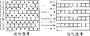
Fig. 3 is the figure of the conversion example of the interlaced image signal S6 that is transformed to interlace mode in order to explanation from the synthesized image signal S5 of row-by-row system.
Fig. 3 (a) becomes the figure of the conversion example under the low level situation for the odd even field identification signal S4 that is input to PI transformation component 5 in order to explanation.Fig. 3 (b) becomes the figure of the conversion example under the situation of high level for the odd even field identification signal S4 that is input to PI transformation component 5 in order to explanation.
Shown in Fig. 3 (a), when odd even field identification signal S4 was low level, the scan line of the odd-numbered line of the synthesized image signal S5 of the row-by-row system that 5 outputs of PI transformation component are imported was made the interlaced image signal S6 of interlace mode, and does not export the scan line of even number line.And, be the scan line of the above-mentioned odd-numbered line of output under 1/2 the speed of the synthesized image signal S5 in being input to PI transformation component 5.
Shown in Fig. 3 (b), when odd even field identification signal S4 was high level, the scan line of the even number line of the synthesized image signal S5 of the row-by-row system that 5 outputs of PI transformation component are imported was made the interlaced image signal S6 of interlace mode, and does not export the scan line of odd-numbered line.And, be the scan line of the above-mentioned even number line of output under 1/2 the speed of the synthesized image signal S5 in being input to PI transformation component 5.
Like this, S4 is low level or high level according to odd even field identification signal, after even number among the synthesized image signal S5 of row-by-row system or odd-numbered line rejecting, the interlaced image signal S6 that exports from PI transformation component 5 just becomes the same signal with the interlaced image signal S1 that is input to input terminal 1.
Also have, PI transformation component 5 be under 1/2 speed of input with half scan line output of the synthesized image signal S5 of the row-by-row system imported, so can be between the synthesized image signal S5 of the row-by-row system of being imported and the interlaced image signal S6 that is exported generation time poor.In other words, from the synthesized image signal S5 of the row-by-row system of lead-out terminal 6 output with from can generation time between the interlaced image signal S6 of the interlace mode of lead-out terminal 7 outputs not poor.
Need mention, more than be to be sprite or OSD that example describes as the image that is synthesized among the first progressive video signal S3, and the present invention is not limited to this.So long as show that the present invention can implement equally as the situation of the image of sub-picture.
Above-described the 1st the related image signal processing apparatus of embodiment of the present invention, after the interlaced image signal S1 of the interlace mode imported is transformed to the progressive video signal S3 of row-by-row system, again with it with show that the signal S2 of sprite or OSD is synthesized to together.Therefore, among the synthesized image signal S5 of the row-by-row system of exporting from lead-out terminal 6, the image of sprite or OSD just can not be unclear owing to having inserted scan line, thereby can prevent image quality decrease.
Besides, be synthesized together, be not transformed to the row number in the field, also increase with regard to the circuit capable of inhibiting scale so will not show display line by the sprite of number management of the row in the frame because sprite is progressive video signal S3 with row-by-row system.
Besides, because in PI transformation component 5, rejected the scan line that inserts by IP transformation component 3, become the same signal and make with the interlaced image signal S6 that exports from lead-out terminal 7, descend because of interlaced image signal S6 so can prevent picture quality from the interlaced image signal S1 of input terminal 1 input.And, as mentioned above, can be from the synthesized image signal S5 of the row-by-row system of lead-out terminal 6 output and poor from generation time between the interlaced image signal S6 of the interlace mode of lead-out terminal 7 outputs.
(the 2nd embodiment)
Fig. 4 is the figure of the structure of expression the 2nd image signal processing apparatus that embodiment is related of the present invention.
Image signal processing apparatus shown in Figure 4 comprises: input terminal 1, input terminal 2, IP transformation component (corresponding to the IP transform component) 13, synthetic portion's (corresponding to compound component) 4, PI transformation component (corresponding to the PI transform component) 5, field signal generator (corresponding to the field signal generator part) 18, lead-out terminal 6 and lead-out terminal 7.
By interlaced image signal S1 (corresponding to the first interlaced image signal) input of input terminal 1 with interlace mode.
The signal S2 (corresponding to the sub-picture signal) that shows sprite or OSD by input terminal 2 inputs.
Field signal generator 18 is that the odd number field still is odd even field identification signal S4 (corresponding to the field identification signal) output of even number half-frames with expression from the interlaced image signal S6 of the interlace mode of PI transformation component 5 output.Need mention, when it is the odd number field, the odd even field identification signal S4 of field signal generator 18 output low levels; And when it is even number half-frames, the odd even field identification signal S4 of 18 output of field signal generator high level.
Lead-out terminal 6, output is from the synthesized image signal S5 of the row-by-row system of synthetic portion 4.
Lead-out terminal 7, output is from the interlaced image signal S6 of PI transformation component 5.
Below, the working condition by the related image signal processing apparatus of the present embodiment of above-mentioned formation is described.
From the interlaced image signal S1 of the interlace mode of input terminal 1 input, in IP transformation component 13 by inserting the progressive video signal S3 (describing in detail afterwards) that scan line is transformed to row-by-row system.Synthetic portion 4 is synthesized together with progressive video signal S3 with from the demonstration sprite of input terminal 2 or the signal S2 of OSD, and output synthesized image signal S5.Synthesized image signal S5 from synthetic portion 4 exports from lead-out terminal 6.From the synthesized image signal S5 of the row-by-row system of synthetic portion 4, in PI transformation component 5, be transformed to the interlaced image signal S6 of interlace mode and from lead-out terminal 7 outputs according to odd even field identification signal S4.
Secondly, Fig. 2 in the reference illustrates the concrete working condition of IP transformation component 13.
When the odd even field identification signal S4 from field signal generator 18 was low level, the interlaced image signal S1 of input odd number field was shown in Fig. 2 (a).In this case, IP transformation component 13 output interlaced image signal S1 make the scan line of the odd-numbered line of progressive video signal S3.At this moment, IP transformation component 13 is made the scan line of the odd-numbered line of progressive video signal S3 with 2 times the speed output interlaced image signal S1 of the interlaced image signal S1 that imported.And the scan line of making the even number line of progressive video signal S3 with the scan line of the front and back row of interlaced image signal S1 inserts and with its output.
On the other hand, when the odd even field identification signal S4 from field signal generator 18 was high level, the interlaced image signal S1 of odd number field was transfused to, shown in Fig. 2 (b).In this case, IP transformation component 13, output interlaced image signal S1 makes the scan line of the even number line of progressive video signal S3.At this moment, IP transformation component 13 is made the scan line of the even number line of progressive video signal S3 with 2 times the speed output interlaced image signal S1 of the interlaced image signal S1 that imported.And the scan line of making the odd-numbered line of progressive video signal S3 with the scan line of the front and back row of interlaced image signal S1 inserts and with its output.
Need mention, relevant scan line insertion, explanation be the method for inserting with front and back two capable scan lines, but be not limited to this.
Because the concrete working condition of PI transformation component 5 is the same with above-mentioned the 1st embodiment, just part reluctantly with what one treasures here, no longer add to have illustrated.
The above in the 2nd image signal processing apparatus that embodiment is related of the present invention, produces odd even field identification signal S4 in field signal generator 18.Compare with the 1st embodiment, just produce the parts difference of odd even field identification signal S4.Therefore, according to this embodiment, can receive and the 1st the same effect of embodiment.
(the 3rd embodiment)
Fig. 5 is the figure of the structure of expression the 3rd image signal processing apparatus that embodiment is related of the present invention.
Image signal processing apparatus shown in Figure 5 comprises: input terminal 1, input terminal 2, IP transformation component (corresponding to the IP transform component) 13, synthetic portion's (corresponding to compound component) 4, linear memory 21, write control part (corresponding to write control unit) 22, read-out control part (corresponding to read-out control unit) 23, HP generating unit (corresponding to horizontal synchronization pulse signal generator part line by line) 24, HI generating unit (corresponding to interlacing horizontal synchronization pulse signal generator part) 25, field signal generator (field signal generator part) 26, clock input terminal 27, lead-out terminal 6 and lead-out terminal 7.
HI generating unit 25, always the clock signal S21 of self-clock input terminal 27 produces horizontal synchronization pulse signal (below be called " interlacing horizontal synchronization pulse the signal ") S23 of interlacing and with its output.
Write control part 22, signal S22 of horizontal synchronization pulse line by line and odd even field identification signal S4 according to from HP generating unit 24 output to write control signal S24 in the linear memory 21.
Read-out control part 23, interlacing horizontal synchronization pulse signal S23 and odd even field identification signal S4 according to from HI generating unit 25 will read control signal S25 and output in the linear memory 21.
Need mention, here,, just explain no longer in addition the identical inscape of working condition of the inscape shown in Figure 4 among its working condition and above-mentioned the 2nd embodiment.
At first, make a brief explanation by the working condition of the 3rd image signal processing apparatus that embodiment is related of above-mentioned formation.
From the interlaced image signal S1 (corresponding to first interlaced image signal) of the interlace mode of input terminal 1 input, in IP transformation component 13, be transformed to the progressive video signal S3 (corresponding to first progressive video signal) of row-by-row system by the insertion scan line.Synthetic portion 4 is synthesized together with progressive video signal S3 with from the demonstration sprite of input terminal 2 or the signal S2 of OSD, and output synthesized image signal S5 (corresponding to second progressive video signal).Synthesized image signal S5 from synthetic portion 4 exports from lead-out terminal 6.Synthesized image signal S5 from the row-by-row system that synthesizes portion 4 is written in the linear memory 21.The picture signal of reading from linear memory 21 is used as picture signal S6 (corresponding to second interlaced image signal) from lead-out terminal 7 outputs.
Secondly, with reference to figure 6, linear memory 21 is described, writes the concrete working condition of control part 22 and read-out control part 23.
Fig. 6 is the figure of the conversion example of the interlaced image signal S6 that uses linear memory 21 in order to explanation, write control part 22 and read-out control part 23, the synthesized image signal S5 of row-by-row system is transformed to interlace mode.
Fig. 6 (a) is for being the figure of the working condition under the low level situation in order to explanation at odd even field identification signal S4; Fig. 6 (b) is for being the figure of the working condition under the situation of high level at odd even field identification signal S4 in order to explanation.Need mention, N is an integer among Fig. 6.
Illustrate that shown in Fig. 6 (a) odd even field identification signal S4 is low level situation.The write control signal S24 that is produced by horizontal synchronization pulse signal S22 line by line only becomes high level under the scan line that the synthesized image signal S5 by row-by-row system represents is the situation of odd-numbered line, in write control signal S24 became that a period of time of high level, progressive video signal S5 write in the linear memory 21.And reading in that a period of time that control signal S25 is a high level of being produced by interlacing horizontal synchronization pulse signal S23, the interlaced image signal S6 that is used as interlace mode reads with 1/2 the speed of synthesized image signal S5.
Illustrate that shown in Fig. 6 (b) odd even field identification signal S4 is the situation of high level.The write control signal S24 that is produced by horizontal synchronization pulse signal S22 line by line only becomes high level under the scan line that the synthesized image signal S5 by row-by-row system represents is the situation of even number line, in write control signal S24 became that a period of time of high level, progressive video signal S5 write in the linear memory 21.And reading in that a period of time that control signal S25 is a high level of being produced by interlacing horizontal synchronization pulse signal S23, the interlaced image signal S6 that is used as interlace mode reads with 1/2 the speed of synthesized image signal S5.
Like this, S4 is low level or high level according to odd even field identification signal, after even number among the synthesized image signal S5 of row-by-row system or odd-numbered line rejecting, the interlaced image signal SG that exports from linear memory 21 just becomes and the same signal of interlaced image signal S1 that is input to input terminal 1.
Also have, because linear memory 21 be under 1/2 speed of input with half scan line output of the synthesized image signal S5 of the row-by-row system imported, so can be between the synthesized image signal S5 of the row-by-row system of being imported and the interlaced image signal S6 that is exported generation time poor.In other words, from can generation time between the interlaced image signal S6 of the synthesized image signal S5 of the row-by-row system of lead-out terminal 6 output and the interlace mode of exporting from lead-out terminal 7 not poor.
As mentioned above, according to the 3rd the related image signal processing apparatus of embodiment of the present invention, can receive and the 1st embodiment or the 2nd the same effect of embodiment.
The effect of invention
In sum, because the present invention is the figure of row-by-row system at the image signal transformation with interlace mode After the image signal, again that it is synthetic with sprite or OSD, so eliminated sprite or OSD Image because having inserted unclear that scan line causes, and can prevent image quality decrease. Also have, will The scan line that inserts in from the image signal transformation of interlace mode to the picture signal of row-by-row system After the rejecting, can prevent that picture quality from descending because of the output of the picture signal of interlace mode.
Claims (9)
1. image signal processing apparatus, wherein,
Comprise:
On the basis of first interlaced image signal of being imported, insert scan line, and with described first interlaced image signal be transformed to first progressive video signal and with its output the IP transform component;
The compound component that described first progressive video signal and the sub-picture signal of being imported in order to show sub-picture synthesize and export as second progressive video signal with it; And
To reject by the described scan line that described IP transform component inserts, and the PI transform component that will described second progressive video signal is transformed to second interlaced image signal and its is exported;
Described second progressive video signal is exported with described second interlaced image signal.
2. image signal processing apparatus according to claim 1, wherein,
The described sub-picture signal that is synthesized in described compound component is the signal in order to demonstration sprite or OSD.
3. image signal processing apparatus according to claim 1 and 2, wherein,
Described IP transform component is such transform component,
On the basis of described first interlaced image signal, insert scan line, and described first interlaced image signal is transformed to described first progressive video signal and, and will represent that described first progressive video signal outputs in the described PI transform component for the field identification signal that the scan line according to the odd number field of described first interlaced image signal or even number half-frames inserts the signal that then obtains with its output;
Described PI transform component is such transform component,
When judging described first progressive video signal according to described field identification signal and insert the signal that the back obtains for scan line according to the odd number field of described first interlaced image signal, the even number line scan line of described second progressive video signal is rejected and it is transformed to described second interlaced image signal
When judging described first progressive video signal according to described field identification signal and insert the signal that the back obtains for scan line according to the even number half-frames of described first interlaced image signal, the odd line interlace line rejecting that it will described second progressive video signal and it is transformed to described second interlaced image signal.
4. image signal processing apparatus, wherein,
Comprise:
On the basis of first interlaced image signal of being imported, insert scan line, and with described first interlaced image signal be transformed to first progressive video signal and with its output the IP transform component;
The compound component that described first progressive video signal and the sub-picture signal of being imported in order to show sub-picture synthesize and export as second progressive video signal with it;
To reject by the described scan line that described IP transform component inserts, and the PI transform component that will described second progressive video signal is transformed to second interlaced image signal and its is exported; And
Is that the odd number field still is the field signal generator part of the field identification signal output of even number half-frames with expression from the field of described second interlaced image signal of described PI transform component;
Described second progressive video signal is exported with described second interlaced image signal.
5. image signal processing apparatus according to claim 4, wherein,
The described sub-picture signal that is synthesized in described compound component is the signal in order to demonstration sprite or OSD.
6. according to claim 4 or 5 described image signal processing apparatus, wherein,
Described IP transform component is such transform component,
When the described field identification signal that receives from described field signal generator part is represented the odd number field, it inserts scan line according to the odd number field of described first interlaced image signal, and with described first interlaced image signal be transformed to described first progressive video signal and with it output
When the described field identification signal that receives from described field signal generator part is represented even number half-frames, it inserts scan line according to the even number half-frames of described first interlaced image signal, and will described first interlaced image signal is transformed to described first progressive video signal and it is exported;
Described PI transform component is such transform component,
When the described field identification signal that receives from described field signal generator part was represented the odd number field, it rejected the even number line scan line of described second progressive video signal, and it is transformed to described second interlaced image signal,
When the described field identification signal that receives from described field signal generator part was represented even number half-frames, it rejected the odd line interlace line of described second progressive video signal, and it is transformed to described second interlaced image signal.
7. image signal processing apparatus, wherein,
Comprise:
On the basis of first interlaced image signal of being imported, insert scan line, and with described first interlaced image signal be transformed to first progressive video signal and with its output the IP transform component;
The compound component that described first progressive video signal and the sub-picture signal of being imported in order to show sub-picture synthesize and export as second progressive video signal with it;
To reject by the described scan line that described IP transform component inserts, and the linear memory that will described second progressive video signal is transformed to second interlaced image signal and its is exported;
Export the production part of horizontal synchronization pulse line by line of horizontal synchronization pulse signal line by line according to the clock signal of being imported;
Interlacing horizontal synchronization pulse production part according to described clock signal output interlacing horizontal synchronization pulse signal;
According to described interlacing horizontal synchronization pulse signal, be that the odd number field still is the field signal generator part of the field identification signal output of even number half-frames from the field of described second interlaced image signal of described linear memory with expression from described interlacing horizontal synchronization pulse production part;
According to from the described signal of horizontal synchronization pulse line by line of the described production part of horizontal synchronization pulse line by line and described field identification signal, control is write write control signal in the described linear memory with described second progressive video signal output to write control unit in the described linear memory from the field signal generator part; And
According to from the described interlacing horizontal synchronization pulse signal of described interlacing horizontal synchronization pulse production part and described field identification signal from described field signal generator part, the control signal of reading that control is read described second progressive video signal from described linear memory outputs to read-out control unit the described linear memory;
Export with described second interlaced image signal of reading from described linear memory from described second progressive video signal of described compound component output.
8. image signal processing apparatus according to claim 7, wherein,
The described sub-picture signal that is synthesized in described compound component is the signal in order to demonstration sprite or OSD.
9. according to claim 7 or 8 described image signal processing apparatus, wherein,
Described IP transform component is such transform component,
When the described field identification signal that receives from described field signal generator part is represented the odd number field, it inserts scan line according to the odd number field of described first interlaced image signal, and with described first interlaced image signal be transformed to described first progressive video signal and with it output
When the described field identification signal that receives from described field signal generator part is represented even number half-frames, it inserts scan line according to the even number half-frames of described first interlaced image signal, and will described first interlaced image signal is transformed to described first progressive video signal and it is exported;
The said write control assembly is such converting member,
When representing the odd number field from the described field identification signal of described field signal generator part, just output is in order to writing the odd line interlace line of described second progressive video signal said write control signal in the described linear memory,
When representing even number half-frames from the described field identification signal of described field signal generator part, just output is in order to write the even number line scan line of described second progressive video signal said write control signal in the described linear memory;
Described read-out control unit is such parts,
Output is used for according to write the described control signal of reading that the scan line of the described progressive video signal in the described linear memory has been read as described second interlaced image signal from the said write control signal of said write control assembly.
Applications Claiming Priority (2)
| Application Number | Priority Date | Filing Date | Title |
|---|---|---|---|
| JP2002152749A JP2003348446A (en) | 2002-05-27 | 2002-05-27 | Video signal processing apparatus |
| JP2002152749 | 2002-05-27 |
Publications (2)
| Publication Number | Publication Date |
|---|---|
| CN1463145A CN1463145A (en) | 2003-12-24 |
| CN1257645C true CN1257645C (en) | 2006-05-24 |
Family
ID=29417155
Family Applications (1)
| Application Number | Title | Priority Date | Filing Date |
|---|---|---|---|
| CNB031362346A Expired - Fee Related CN1257645C (en) | 2002-05-27 | 2003-05-19 | Image signal processor |
Country Status (6)
| Country | Link |
|---|---|
| US (1) | US20030218692A1 (en) |
| EP (1) | EP1367820A3 (en) |
| JP (1) | JP2003348446A (en) |
| KR (1) | KR20030091804A (en) |
| CN (1) | CN1257645C (en) |
| TW (1) | TWI266532B (en) |
Families Citing this family (7)
| Publication number | Priority date | Publication date | Assignee | Title |
|---|---|---|---|---|
| CN100493160C (en) * | 2003-04-09 | 2009-05-27 | 松下电器产业株式会社 | OSD-synthesized image decoding device and OSD-synthesized image decoding method |
| EP1741282A1 (en) * | 2004-04-30 | 2007-01-10 | Nvidia Corporation | Method and apparatus for vertically scaling pixel data |
| EP1619886A1 (en) * | 2004-07-22 | 2006-01-25 | Harman Becker Automotive Systems GmbH | Video format adaptation |
| JP2006129069A (en) * | 2004-10-28 | 2006-05-18 | Canon Inc | Image pickup device and image pickup method |
| JP4933209B2 (en) * | 2006-10-05 | 2012-05-16 | パナソニック株式会社 | Video processing device |
| JP5023805B2 (en) * | 2007-05-16 | 2012-09-12 | ソニー株式会社 | Image processing apparatus, image processing method, and program |
| US20080291323A1 (en) * | 2007-05-22 | 2008-11-27 | Seiko Epson Corporation | Image processing device, data recording device, and method of controlling image processing device |
Family Cites Families (14)
| Publication number | Priority date | Publication date | Assignee | Title |
|---|---|---|---|---|
| US5327156A (en) * | 1990-11-09 | 1994-07-05 | Fuji Photo Film Co., Ltd. | Apparatus for processing signals representative of a computer graphics image and a real image including storing processed signals back into internal memory |
| US5325131A (en) * | 1993-05-03 | 1994-06-28 | Tektronix, Inc. | Multiformat television switcher |
| US5828786A (en) * | 1993-12-02 | 1998-10-27 | General Instrument Corporation | Analyzer and methods for detecting and processing video data types in a video data stream |
| KR960042456A (en) * | 1995-05-08 | 1996-12-21 | 이민화 | Sequential Scanning Ultrasonic System Display |
| US5530484A (en) * | 1995-05-19 | 1996-06-25 | Thomson Multimedia S.A | Image scanning format converter suitable for a high definition television system |
| US5963261A (en) * | 1996-04-29 | 1999-10-05 | Philips Electronics North America Corporation | Low cost scan converter for television receiver |
| JP3514063B2 (en) * | 1997-02-20 | 2004-03-31 | 松下電器産業株式会社 | Receiver |
| US6798458B1 (en) * | 1998-10-01 | 2004-09-28 | Matsushita Electric Industrial Co., Ltd. | Image signal conversion equipment |
| KR100326919B1 (en) * | 1999-08-23 | 2002-03-13 | 윤종용 | apparatus and method for down-converting |
| JP2001203988A (en) * | 2000-01-21 | 2001-07-27 | Nec Corp | Image decoding device, semiconductor device, and image decoding method |
| JP2001231016A (en) * | 2000-02-15 | 2001-08-24 | Matsushita Electric Ind Co Ltd | Video signal reproducing device |
| US6927801B2 (en) * | 2000-11-20 | 2005-08-09 | Victor Company Of Japan, Ltd. | Video signal processing apparatus and video displaying apparatus |
| US7012648B2 (en) * | 2001-04-02 | 2006-03-14 | Matsushita Electric Industrial Co., Ltd. | Image conversion method and image conversion apparatus |
| US6573941B1 (en) * | 2002-04-22 | 2003-06-03 | Thomson Licensing Sa | Low bit rate compression format conversion for improved resolution |
-
2002
- 2002-05-27 JP JP2002152749A patent/JP2003348446A/en not_active Withdrawn
-
2003
- 2003-04-14 US US10/412,392 patent/US20030218692A1/en not_active Abandoned
- 2003-05-16 EP EP03011225A patent/EP1367820A3/en not_active Withdrawn
- 2003-05-19 CN CNB031362346A patent/CN1257645C/en not_active Expired - Fee Related
- 2003-05-27 TW TW092114232A patent/TWI266532B/en not_active IP Right Cessation
- 2003-05-27 KR KR10-2003-0033538A patent/KR20030091804A/en not_active Application Discontinuation
Also Published As
| Publication number | Publication date |
|---|---|
| US20030218692A1 (en) | 2003-11-27 |
| KR20030091804A (en) | 2003-12-03 |
| EP1367820A2 (en) | 2003-12-03 |
| EP1367820A3 (en) | 2007-08-29 |
| JP2003348446A (en) | 2003-12-05 |
| CN1463145A (en) | 2003-12-24 |
| TW200400760A (en) | 2004-01-01 |
| TWI266532B (en) | 2006-11-11 |
Similar Documents
| Publication | Publication Date | Title |
|---|---|---|
| CN1291589C (en) | Frame frequency conversion method of interlaced and line-by line video signals | |
| CN1112027C (en) | Picture element number conversion device | |
| CN1599414A (en) | Solid-state image sensing apparatus | |
| CN1649397A (en) | Device and method for processing video signal | |
| CN1638447A (en) | Image adaptive deinterlacing method and device based on edge | |
| CN1685715A (en) | Video display apparatus and video display method | |
| CN1205820C (en) | Signal transmitting device and signal receiving device | |
| CN1162832C (en) | Image display device | |
| CN1225120C (en) | Image processing device, image processing method, recording medium and program | |
| CN1257645C (en) | Image signal processor | |
| CN101042849A (en) | Information processing apparatus and information processing method | |
| CN1181670C (en) | Overlay image processor and display device | |
| CN101039396A (en) | Image output apparatus and method using numbers of chroma key color | |
| CN1758743A (en) | Use the image processing equipment and the method thereof of shake mapping | |
| CN1595973A (en) | Method and system for converting interlacing video stream to line-by-line video stream | |
| CN1270527C (en) | Scan conversion appts. | |
| CN1465180A (en) | Method and device for generating a video signal | |
| US20090040373A1 (en) | Interface converting circuit | |
| CN1822657A (en) | Method and apparatus for displaying frame rate altered video on interlaced display device | |
| CN100350796C (en) | Image data conversion method, conversion circuit, and digital camera | |
| CN1152362C (en) | Device and method for image displaying | |
| CN1605196A (en) | Image signal processing apparatus and processing method | |
| CN1168310C (en) | Signal processing apparatus and method | |
| CN1605198A (en) | Image signal processing apparatus and processing method | |
| CN1167261C (en) | Method for converting video frequency data frame rate and its apparatus |
Legal Events
| Date | Code | Title | Description |
|---|---|---|---|
| C06 | Publication | ||
| PB01 | Publication | ||
| C10 | Entry into substantive examination | ||
| SE01 | Entry into force of request for substantive examination | ||
| C14 | Grant of patent or utility model | ||
| GR01 | Patent grant | ||
| C17 | Cessation of patent right | ||
| CF01 | Termination of patent right due to non-payment of annual fee |
Granted publication date: 20060524 Termination date: 20120519 |