CN1557072A - Data communications method and system using buffer size to calculate transmission rate for congestion control - Google Patents
Data communications method and system using buffer size to calculate transmission rate for congestion control Download PDFInfo
- Publication number
- CN1557072A CN1557072A CNA028183991A CN02818399A CN1557072A CN 1557072 A CN1557072 A CN 1557072A CN A028183991 A CNA028183991 A CN A028183991A CN 02818399 A CN02818399 A CN 02818399A CN 1557072 A CN1557072 A CN 1557072A
- Authority
- CN
- China
- Prior art keywords
- data
- rate
- buffer
- receiver
- stream
- Prior art date
- Legal status (The legal status is an assumption and is not a legal conclusion. Google has not performed a legal analysis and makes no representation as to the accuracy of the status listed.)
- Pending
Links
Images


Classifications
-
- H—ELECTRICITY
- H04—ELECTRIC COMMUNICATION TECHNIQUE
- H04L—TRANSMISSION OF DIGITAL INFORMATION, e.g. TELEGRAPHIC COMMUNICATION
- H04L47/00—Traffic control in data switching networks
- H04L47/10—Flow control; Congestion control
- H04L47/30—Flow control; Congestion control in combination with information about buffer occupancy at either end or at transit nodes
-
- H—ELECTRICITY
- H04—ELECTRIC COMMUNICATION TECHNIQUE
- H04L—TRANSMISSION OF DIGITAL INFORMATION, e.g. TELEGRAPHIC COMMUNICATION
- H04L47/00—Traffic control in data switching networks
- H04L47/10—Flow control; Congestion control
-
- H—ELECTRICITY
- H04—ELECTRIC COMMUNICATION TECHNIQUE
- H04L—TRANSMISSION OF DIGITAL INFORMATION, e.g. TELEGRAPHIC COMMUNICATION
- H04L47/00—Traffic control in data switching networks
- H04L47/10—Flow control; Congestion control
- H04L47/26—Flow control; Congestion control using explicit feedback to the source, e.g. choke packets
- H04L47/263—Rate modification at the source after receiving feedback
Abstract
A data transmission method and system is disclosed in which one or more data streams are transmitted at respective transmission rates which are controlled to prevent data buffers in the receiver from overflowing. In some embodiments feedback data concerning the state of each buffer in a receiving client is received at the transmitting server, and used to adapt the sending rates to achieve the effect. Information indicative of the data decode rates or the fill extent of each buffer is communicated to the server as the feedback data. In other embodiments the server makes an open-loop estimate of the remaining space in the buffer, and controls the transmission rate accordingly. A data receiving method and system adapted to receive the data streams is also disclosed.
Description
Technical field
The present invention relates to a kind of method and system that is used for data communication, more specifically, relate to a kind of method and system that is used for sending one or more data flow by network, and a kind of method and system that is used to receive above-mentioned transmission data.In addition, the invention still further relates to a kind of computer-readable recording medium of storage computation machine program, when moving this computer program on computers, its control computer is carried out aforesaid data method of sending and receiving.
Background technology
The telecommunications network that is used for data communication has in recent years had great increase on quantity, scope and number of users.Before, most of data communication of carrying out on this telecommunications network feature was that these data are " based on message " basically.The meaning of " based on message " is that those data in transmission over networks have formed, for example the part of email message, the file in transport process or other application datas of transmitting between client-server system.A principal character of the data of this " based on message " is that it is not a time-critical especially, and time-critical is meant that data must arrive receiver terminal in certain transmission time in order to make data useful.On the contrary, if data have arrived receiver in a rational time quantum, then it remains useful to the end user.The example of the data of this " based on the message " that knows previous the sixth of the twelve Earthly Branches for example is standard electronic mail and the file that uses file transfer protocol (FTP) (FTP) transmission.
Recently, attentiveness has been transferred to the network and the relevant device that can send data with continuous data stream from transmitter to receiver from the ability of the traditional message based data of data communication network transmission.The value of this data usually is time-critical, because network must as far as possible smoothly and be sent to receiver terminal to data from transmitter apace, preferably avoids the needs of retransmission data.Next an example of this data stream type transmission system of knowing the sixth of the twelve Earthly Branches is in the prior art described according to Fig. 1.
Usually, the data that will be transmitted as a stream are multi-medium datas, such as the Voice ﹠ Video data.These Voice ﹠ Video data may such as news or sport event, perhaps may derive from from on-the-spot audiovisual broadcast, for example, allow them to watch the video-on-demand service of TV programme and film according to their selection when the user selects.Yet no matter what the source of these data is, corresponding audio ﹠ video data feed must be at first by digital coding suitably, so that this Voice ﹠ Video data-signal is compressed into a size that is suitable in transmission over networks.Usually, carry out the Voice ﹠ Video coding according to one among the different mpeg standards.
After the Voice ﹠ Video digital coding, will be coded data be delivered to the webserver, in the webserver, data were stored in before being transmitted through the network to client computer independently in the audio buffer and video buffer.
After buffering, as following more detailed argumentation, data are sent out by network, and are received by receiver, wherein these data of buffering before decoding.In receiver, carry out decoding, and the data of being decoded are sent to the application program on this receiver, moved in order to reproduce by a suitable decoder.
Yes that those form the network of internets for a kind of in the most general network type of current use, and it uses Internet protocol (IP) to transmit data at the network of network layer with the form of IP datagram.Provide data to transmit by transport-layer protocols (transmission control protocol (TCP) and User Datagram Protoco (UDP) (UDP)) by network layer.At TCP and UDP all is as known in the art, and at for example Tannenbaum A.S., " computer network " third edition, Prentice Hall describes in the PP521-542 page or leaf to some extent.
UDP is by through being usually used in the stream data service by network, and in particular for the stream audio and video data.Yet UDP is a kind of Connectionless Transport Protocal, and does not therefore provide the service quality controlling mechanism, can not allow for a user and guarantee special service quality.In addition, UDP is used for stream data has caused other problem,, and do not consider the network congestion state and at the state of the receive data buffer of receiving terminal because it always sends out data with identical transmission rate, this is easy to cause packet loss, and obliterated data thus.That is to say that when using UDP for stream data, if network congestion takes place so, UDP continues to send packet with identical transmission rate, thereby has encouraged this network congestion.Under the worst case that is not used in the mechanism that alleviates network congestion, the possibility of result is to lose majority or total data stream packets.Similarly, if the message transmission rate of this data flow is higher than the speed that the receiver buffer empties, then buffer can overflow, and the mechanism of another kind of packet loss is provided thus.Ill-effect in this case is dual---the data of overflowing that not only made receiver, these data of overflowing will cause the reproduction of poorer quality under the situation of real-time multimedia data, and this network divides into groups to have wasted bandwidth their overflowing of destination subsequently owing to having sent those.
By use TCP as the network transmission protocol can alleviate slightly above-mentioned with use UDP to carry out stream data to transmit the problem that is associated.TCP is a kind of Connection-oriented Protocol, and its packet acknowledgement provides to sending terminal, and this sends the controlled quentity controlled variable of terminal permission to the increase of message transmission rate.More specifically, TCP comprises a transmission rate control algolithm solving network congestion, as in above-mentioned 536 to 539 pages of descriptions.TCP transmission control algolithm be known " addition-increases-multiplication-minimizing " algorithm of type, wherein in case reach basic threshold transfer rate, then transmission rate is with a kind of add mode, one of a branch winding increases group by group, up to dividing into groups, so transmission rate reduces in a kind of mode of multiplication subsequently, for example, transmission rate is reduced by half.Therefore when packet loss took place, TCP transmission rate algorithm had been considered network congestion by the transmission rate that reduces data flow, but the multiplication of minimizing means that the variation of the data throughout by network can be quite high.
Fig. 2 illustrates an example that uses the data throughout of TCP, will figure out message transmission rate thus and can produce sizable variation with respect to the time.When using TCP in transmission rate high relatively variation mean that it is not to be suitable for stream data especially to use, wherein, preferably transmission rate is with respect to the stable state of time smoothing ground variation.In addition, TCP transmission rate control algolithm is not considered the receiver buffer state, thereby if TCP flow transmission speed is higher than decode rate in receiver, has then introduced the possibility of packet loss again.As the situation of UDP, packet loss in the destination demonstrates dual ill-effect---and not only receiver has been lost the data of overflowing, it will cause the reproduction of poorer quality under the real-time multimedia data situation, and this network has been wasted bandwidth owing to sending those groupings of overflowing of losing in their destination subsequently.
In the time will sending two or more data flow that comprise related data (such as the Voice ﹠ Video data) simultaneously, use the relevant problem of the frequent variations of the message transmission rate that TCP causes more complicated with the convection type data.In this case, when using TCP and as an example with the Voice ﹠ Video data in independent data stream, transmitted, since audio stream by with video flowing independently TCP be connected transmission, so each corresponding connection will be used its transmission rate control algolithm, and do not consider the transmission rate of another stream.Final result is, through after a while, become basically identical with video flowing of the data throughout of the audio stream by network, however in fact for most audio-visual source, the video data that sends of time per unit is more much more than voice data usually.So the equal of transmission rate between audio ﹠ video stream that obtains by TCP can have such effect at receiver, promptly, influence the suitable reproduction of data, owing to do not send because the data of these two types are not the speed that is complementary with the generation with the Voice ﹠ Video data respectively, usually there are enough voice datas to be stored in and are used in the receiver audio buffer reproducing, but in the receiver video buffer, do not have video data enough as voice data to be used for reproducing simultaneously by the audiovisual applications program.
Because to each corresponding stream application transmission rate control algolithm separately, especially because the character of the multiplication minimizing of standard TCP transmission rate control algolithm has produced further problem.Consider to be independent of video flowing and connect the transmission audio stream, and wherein video flowing also uses the situation that TCP sends by TCP.Usually, as previously explained, the average throughput of each connection is basic identical, but since when packet loss occurring in stream therein the multiplication of transmission rate reduce, in fact may have very big difference any being engraved between two streams transmission rate separately when specific.The potential big short term variations of these transmission rates between two stream has been introduced uncertainty to transfer of data, and may cause the problem of data buffer in the receiver, because when interim big difference occurring, thereby audio buffer for example may be full of and overflow obliterated data, but corresponding video buffer may be cleared, the generation that has stoped AV to reproduce thus.
Before, each stream do not have the udp protocol of connection by being used, and send each stream to keep the correct ratio of data between these streams with suitable transmission rate simply, handled owing to a plurality of data flow being used the problems referred to above that TCP transmission rate control algolithm causes.But as discussed previously, UDP does not consider that the state of receiver buffer comes control transmission speed.Therefore, still need to keep the transmission rate control and the system of stability of the transmission rate of each stream, this method and system is still considered the state of buffer in the receiver simultaneously, to prevent the unnecessary packet loss in receiver.
Summary of the invention
The present invention is by providing a kind of data transmission method and system handles the problems referred to above, and the webserver is determined the state of receiver buffer in this method and system.Server sends data flow with transfer of data bit rate subsequently, and the message transmission rate of controlling this stream is overflowed to prevent the receiver buffer.The control of transmission rate also has the effect that the smooth steady state transmission rate is provided for data flow.Can carry out the receiver buffer state in the mode of open loop or closed loop determines.
Be above-mentioned purpose, according to a first aspect of the invention, provide a kind of method, may further comprise the steps by transmitted data on network:
Form with data flow sends to data on the network to send to receiver with a message transmission rate;
Determine at least one or more a plurality of feature of the data buffer in the receiver, in this data buffer, stored the data that receive; And
In response to the message transmission rate that determined feature is come control data stream, overflow to prevent the data buffer in the receiver.
According to a second aspect of the invention, also provide a kind of system that is used for by transmitted data on network, having comprised:
The data flow transmission device is used for data being sent on the network to send to receiver with a transfer of data bit rate in data flow;
Feature is determined device, is used for determining that receiver stored at least one or more a plurality of feature of the data buffer of the data that receive; And
Data flow control device is used for coming in response to determined feature the message transmission rate of control data stream, overflows to prevent the data buffer in the receiver.
One or more feature of data buffer by the data determining to receive in this stream of storage in the receiver, the invention enables control data transmission speed by this way, that is, make receiver end can be owing to buffer does not overflow lost packets.Its advantage that provides is to have improved network bandwidth utilance, as under the situation of retransmitting any lost data packets, does not lose because data at first can not overflowed by buffer, does not therefore need to retransmit.In addition, in the situation of the real time data that does not for example usually need data re-transmitting, can realize the reproduction of real time data with smooth mode more, and have the reproduction quality of expection simultaneously.
It can be open loop or closed loop that feature is determined.Especially, when determining to be open loop, server only writes down it and how many groupings is sent to receiver, and how many decode rate of those groupings will be when described.By knowing the size of receiver buffer in advance, server can keep the estimation in how many spaces of residue in the receiver buffer, and correspondingly adjusts transmission rate.
When feature was determined to be closed loop, receiver sent the information of this one or more feature of expression to server, and server uses the information that the receives basis as transmission rate control then.
Preferably, this one or more feature is included in the decode rate of data in receiver that sends in the described stream at least, and the transmission rate of data flow is further controlled to being at least the function of this receiver decoding speed.By the transmission rate of data flow and decode rate are connected, can realize stable stable state transmission from transmitted from transmitter to receiver, it is particularly suitable for the streaming real time data.
In other embodiments, one or more feature of this of data buffer comprises the information of expression buffer residual capacity.By determining remaining buffer capacity, can suitably realize changing continuously or step by step of transmission rate, for example, therefore require less buffer capacity to reappear identical information by the data that send being changed over data with lower quality coded.
In other preferred embodiment, this method comprises that further calculating should carry out the step of the peak transfer rate that data flow sends, and transmission bit rate is controlled within the maximum rate that is calculated.
Considered the peak transfer rate of the transmission rate formula calculated data stream that network congestion is derived by use, peak transfer rate that can control flows, embodying those congested in that part of network that stream is routed to, thereby minimize the influence of other packet loss mechanism.
Preferably, calculate peak transfer rate to provide the average data throughput by network, this data throughout is similar to the throughput of using transmission control protocol (TCP) and obtaining, so that data flow can be called as " TCP close friend's ".By using TCP close friend's transmission rate controlling schemes, can obtain following advantage, get final product control transmission speed with the embodiment network congestion, and other competition TCP that adapts in the network connects.
Preferably, this method further may further comprise the steps: a plurality of data flow are sent to network to be transferred to receiver, and each data flow is transmitted with message transmission rate separately; Determine at least one or more a plurality of feature of data buffer that each has stored the data flow that receives; And, control each stream transmission rate separately in response to the feedback data that receives, overflow to prevent data buffer.
According to above, the present invention also has in application from transmitter to one or more identical or different receiver that transmit a plurality of data flow from.
Preferably, the data flow of transmission comprises the audio or video data.When transmitting two kinds of data flow at the same time, preferably, one of them stream comprises voice data, and another stream comprises video data.Preferably, the Voice ﹠ Video data are correlated with, and reproduce simultaneously because be expected at receiver end, and for example video data is TV programme or film, dub and voice data is it.The transmission of the Voice ﹠ Video data during the present invention is used in particular for flowing, wherein the present invention can control the transmission rate of each stream, reaching level and smooth substantially, and prevents that the receiver buffer from overflowing.Preferably, the control transmission rate is with the read-out speed of coupling receiver buffer.
Preferably, the present invention can further be set to receive feedback data from described or each receiver, this feedback data is represented one or more in the receiving velocity value of two-way time (RTT), Loss Rate value and/or receiver, and calculates the overall transmission rate as the function of one or more value that receives of conduct of being represented by feedback data in addition.Two-way time be data from transmitted from transmitter to receiver and get back to the required THE MEASUREMENT OF TIME of transmitter, and the Loss Rate value is the tolerance of the data volume that sends to receiver of losing in the network.The receiving velocity value is the bit number that inner receiver receives in two-way time.
By the feedback from the receiver to the server is provided, can provide up-to-date information to server, this information for example represents to cause on the network congestion situation of packet loss.The available transmission rate of the maximum that server then can flow according to the state computation of current network, thereby the transmission rate of optimization transport stream.
In addition, according to a third aspect of the invention we, further provide a kind of computer-readable recording medium of storage computation machine program, when moving on computers, this program can be controlled the method for computer execution according to first aspect present invention.
Preferably, this computer-readable recording medium can be any in CD, disk, magneto optical disk, solid-state computer memory or any data storage medium that other is fit to.
According to a forth aspect of the invention, also provide a kind of and received the method for data from network, these data according to before about of the present invention first or the method or the system of second aspect explanation send, this method may further comprise the steps:
Reception is with a message transmission rate data flow transmitted;
The data passes that receives is arrived data buffer, to cushion therein;
At least one of measurement data buffer or more a plurality of feature; And
Measured features is sent to transmitter, to be used to calculate transmission rate from the data flow of transmitter transmission.
Send it back transmitter by feature, can overflow to prevent the data buffer in the receiver so that transmitter can be controlled its message transmission rate with data buffer, and loss of data.
Preferably, in fourth aspect, this method further may further comprise the steps: with a decode rate data in the data buffer are decoded, and data decode speed is sent to transmitter as in the feature of described measurement at least one.By data decode speed is delivered to transmitter, can be so that transmitter can be controlled its transmission rate, to obtain stable stable state transmission rate, wherein decode rate is complementary with transmission rate basically, has preferably solved the packet loss in the network.
In addition, preferably, this one or more feature further comprises the information of expression buffer residual capacity.By this information is delivered to transmitter, transmitter can use the substep of speed to change the transmission rate that flows as the further control data of stringent effort, overflows to prevent buffer.
According to a fifth aspect of the invention, also provide a kind of system that is used for receiving data from network, these data according to before about of the present invention first or the method or the system of second aspect explanation send, aspect the 5th in, this system comprises:
Data sink is used for receiving with a message transmission rate data flow transmitted;
Data bus means is used for the data passes that receives to data buffer, to cushion therein;
The buffer monitoring arrangement is used at least one or more a plurality of feature of measurement data buffer; And
Data transmission device is used for measured features is sent to transmitter, to be used to calculate the transmission rate from the data flow of transmitter transmission.
The identical feature and advantage that a fifth aspect of the present invention has showed and before illustrated about fourth aspect, and further feature and advantage.
In addition, according to a sixth aspect of the invention, also provide a kind of computer-readable recording medium of storage computation machine program, when moving on computers, this program-con-trolled computer is carried out method according to a forth aspect of the invention.As in the third aspect, can be implemented as any or more kinds of in disk, CD, magneto optical disk, the solid-state computer memory etc. according to the storage medium of sixth aspect present invention.
Description of drawings
By the description of the following embodiments of the invention that only provide in an exemplary fashion with reference to accompanying drawing, other features and advantages of the present invention will become obviously, and identical label is represented identical part in the accompanying drawing, wherein:
Fig. 1 is the schematic block diagram of assembly of the multimedia streaming system of explanation prior art;
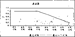
Fig. 2 is the chart of data throughout of the network of the explanation Transmission Control Protocol that uses prior art;
Fig. 3 is the block diagram that explanation is used for the setting of the server of the embodiment of the invention and client devices;
Fig. 4 is the block diagram that is used for the primary clustering in the server apparatus of the embodiment of the invention;
Fig. 5 is the block diagram that is used for the functional unit in the client devices of the embodiment of the invention;
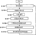
Fig. 6 is the flow chart by the method step of the execution of the server apparatus in the first embodiment of the invention;
Fig. 7 is the flow chart by the method step of the client devices execution that is used for first embodiment of the invention;
Fig. 8 is the flow chart that explanation is used for the related step of the calculating of losing incident rate of embodiments of the invention;
Fig. 9 is the chart of the filter factor that uses in embodiments of the present invention;
Figure 10 is the block diagram that is used for the filter assembly in the receiver device of embodiments of the invention;
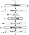
Figure 11 is the flow chart by the method step of the execution of the server apparatus in the second embodiment of the invention;
Figure 12 is the flow chart by the method step of the client devices execution of using in second embodiment of the invention; And
Figure 13 is to use the chart of the data throughout that passes through network of one of data flow of embodiments of the invention realization.
Embodiment
Constitute the structure and the operation of the various assemblies of three embodiment of the present invention now with reference to Fig. 3-13 explanation.It should be noted that, Shuo Ming preferred embodiment is intended to be applied to as the present invention the nonrestrictive example of the multi-medium data transmission of Voice ﹠ Video data for example herein, and the present invention can almost use in any application that sends one or more data flow by network.
Term in description " transmitter " and " server " use interchangeably, and term " receiver " and " client computer " also are like this.
Each embodiment of the present invention that this paper will illustrate can use identical system component, although be with different degree, and there are differences on their method of operation.Thereby next carry out general explanation to the equipment that can be used for each embodiment, the operation of each embodiment then is described respectively successively.
Two basic modules that constitute the system of the preferred embodiment of the present invention have been described in Fig. 3.Here, as can be seen, provide the server 40 that is provided with first video buffer 42 and second video buffer 43 therein.First video buffer 42 is set to store the coding video frequency data that has carried out coding with first video coding rate, and second video buffer 43 is arranged to storage with the more coding video frequency data of second video coding rate coding, and wherein this second video coding rate is lower than the code rate that is stored in the coding video frequency data in first buffer 42.It should be noted that being stored in two buffers 42 is that identical original video data obtains with coding video frequency data in 43, but it only is to use different code rates to be encoded, to provide different coding video frequency datas.Usually, because it is higher to be used for generating the code rate of the coding video frequency data that is stored in first buffer 42, so the coding video frequency data in first buffer 42 will be bigger than the coding video frequency data with lower code rate coding that is stored in accordingly in second video buffer 43.Preferably use and H.623 encode coding video data, although be to be understood that and can use any suitable video coding technique, MPEG etc. for example.
An audio data buffer 44 that is used for the memory encoding voice data also is provided in server 40.Note that in a preferred embodiment and only voice data is encoded, therefore only need single audio buffer with single encoded speed.Preferably, use the AMR audio coding that voice data is encoded, although can use any audio coding technology that other is fit to, MP3 etc. for example.
Except server 40, also provide one or more client computers 50 in a preferred embodiment.For the sake of clarity, Fig. 3 has shown single client computer, but server might be served the client computer more than, and can send to each client computer to the data flow more than.In the present embodiment, each client computer comprises a video buffer 52 and an audio buffer 54.Video buffer 52 is set to receive and store the coding video frequency data that receives from server 40.The coding video frequency data that video buffer 52 storages receive, the Video Decoder that provides in client computers takes out coding video frequency data from video buffer 52, be used to decode and reproduce the vision signal that wherein is encoded.Similarly, audio buffer 54 receives the coding audio data that sends from server 40, coding audio data is cushioned, and the audio decoder that provides in client computers takes out coding audio data from audio buffer 54, is used to decode and reproduce the audio signal that wherein is encoded.
In order between server computer and described or each client computers, to provide data communication, between server 40 and described or each client computer 50, provide first User Datagram Protoco (UDP) (UDP) to connect 10, connect from server 40 transmission coding video frequency datas along this.Similarly, also provide the 2nd UDP to connect 20 from server 40 to described or each client computer 50, connected the transmission coding audio data along this.By server below will control for the mode of each embodiment explanation of the present invention connects 10 and 20 separately transmission rates to UDP.
Except connecting at the UDP between server and described or each client computer, in first and second embodiment, between described or each client-server, set up transmission control protocol (TCP) and connect 30, to be used for mainly turning back to the transmission of the control messages of server from described or each client computer, connect 10 and 20 transmission rate so that can control two UDP effectively, the further details that sends to the feedback data of server in each embodiment by the TCP connection from described or each client computer will be discussed after a while.
Go to Fig. 4 now, Fig. 4 with the form illustration of block diagram the assembly that needs in the server computer 40 in the preferred embodiment of the present invention.It should be noted that Fig. 4 only illustration necessary those server components of operation of at least one embodiment of the present invention, and do not have the illustration server system to operate those required other assemblies, be to be understood that, the reader of expection is those skilled in the art, and they can identify those required additional assemblies of complete operation server system.
In a preferred embodiment, server computer 40 comprises multimedia application controller 41, and it is arranged to received code voice data and coding video frequency data, and as before about as described in Fig. 3, the data that buffering receives in buffer 42,43 and 44.Please note that for clarity sake these buffers do not show on Fig. 4.Multimedia application controller 41 connects 30 by TCP control messages is sent to client computers 50, and receives the control messages from client computers 50.In addition, the multimedia application controller provides coding video frequency data and coding audio data from suitable buffer to network connecting module 47, and this network connecting module is carried out packetizing to data, is used for transmitting to client computers by network.Therefore, operational network link block 47 is with from multimedia application controller received code Voice ﹠ Video data, packet is changed into the form that is fit to transmission, and packet is sent on the network with two corresponding UDP message streams with suitable transmission rate respectively.Data flow transmission rate is separately calculated according to the suitable transmission rate formula that will be each embodiment discussion after a while by transmission rate calculator 46.Transmission rate calculator 46 is being delivered to network connecting module 47 for the transmission rate of Voice ﹠ Video data-flow computation, so that the transmission rate of being calculated is notified to network connecting module 47.In first and second embodiment, connect by TCP from client computers to the multimedia application controller, the input data of the transmission rate formula that acquisition is calculated in transmission rate calculator 46, those input data are delivered to the transmission rate calculator by the connection that is fit to from the multimedia application controller.
Network controller module 48 further is provided, has connected 47 with Control Network and carry out suitable packet process, to allow in transmission over networks Voice ﹠ Video data.
In addition, further provide the re-transmission buffer 49 as memory etc., it is arranged to and connects 47 from network and receive packet and appropriate control signals, and if network connect 47 must retransmit buffering packets the time, the packet that buffering receives.The buffering of the packet that is sent and re-transmission and the present invention are irrelevant, and therefore do not set forth further details here.
Although in Fig. 4, do not show, should be noted that still server computer 40 further comprises at least one computer-readable recording medium, this computer-readable recording medium storage is used for the operation of Control Server computer to carry out computer program of the present invention.This computer-readable recording medium can be any known type, and can be combined to form by any one or its in CD, disk, magneto optical disk, solid-state computer memory or any data storage medium that other is fit to especially.
Fig. 5 is the block diagram of the functional unit of the client computers 50 that needs in the embodiments of the invention.Similar to the explanation of server computer 40, be to be understood that Fig. 5 does not have the required all component of exemplified operation client computers 50, and only illustration those functional block components of action need of at least one preferred embodiment of the present invention.Which as those skilled in the art's reader, be to be understood that in order to carry out additional assembly of complete action need client computers.
In client computers 50, further provide and be arranged to the network connecting module 57 that receives the packet one or more data flow from network.The control information relevant with the data in one or more data flow that receives is passed to the measuring calculator (metrics calculator) 56 that is used for the number of computations value, these quantitative values are represented some feature of the data flow that receives, and the quantitative value of being calculated is passed to feedback transmitter 58, passes back on network in order to connect 30 as control messages by TCP.Provide the further information that relevant quantitative value is calculated after a while.
Network connects 57 and receives the Voice ﹠ Video data flow, and extracts coded audio and video data in the grouping from each stream.Coded audio and video data are delivered to buffer controller 59 subsequently, and buffer controller 59 is fed to audio buffer 54 to the coding audio data that receives, and the coding video frequency data that receives is fed to video buffer 52.Buffer control unit 59 further is set to monitor the state of audio buffer 54 and video buffer 52, and is how full to determine that each buffer has, and the speed that empties of each buffer, and this rate representation is stored in the decode rate of the data in the buffer.Audio decoder 53 further is provided, and it can read coding audio data from audio buffer 54, and coding audio data is decoded, to provide decoding audio data as output.Similarly, provide from video buffer 52 and taken out coding video frequency data, and coding video frequency data has been decoded, with the Video Decoder 55 that video output signals is provided.
Although in Fig. 5, do not show, should be noted that client computers further comprises at least one computer-readable recording medium, its storage is used to control the operation of client computers to carry out computer program of the present invention.This computer-readable recording medium can be any known type, and can be formed by any or its combination in CD, disk, magneto optical disk, solid-state computer memory or any data storage medium that other is fit to especially.
The basic functional blocks that constitutes server apparatus of the present invention and client computes machine equipment has been described, now the operation of the preferred embodiment of the present invention will be described successively.
First embodiment
Referring now to Fig. 6 to the 10 explanation first embodiment of the present invention, first embodiment be specifically related to one or more independently stream send to identical or different client computer, and with the transmission rate of closed-loop fashion control flows.
Fig. 6 is the flow chart according to the step of being carried out by server computer 40 of the first embodiment of the present invention.At first, in step 102, transmission rate calculator 46 total bandwidth for will using from each data-flow computation that server computer 40 sends.The transmission rate upper limit that the transmission rate of this each independent data flow of max_rate value representation should not surpass.Calculate the max_rate value according to following principle.
Typically, the current previous multimedia conferencing application of using in the Internet is based on the UDP host-host protocol, this does not provide the service quality controlling mechanism just as previously discussed, and therefore can not carry out such as for example network congestion is compensated required control measure.Therefore, as mentioned above, competition TCP connection reduces their transmission rate when network congestion occurring, and does not have any speed of UDP communication to reduce.
For fear of this problem, in the first embodiment of the present invention, adopt congestion control scheme to strengthen UDP Voice ﹠ Video data flow, the max_rate CALCULATION OF PARAMETERS has formed the part of this congestion control scheme.More particularly, calculate this parameter m ax_rate and provide maximum transmission rate with stream to " TCP close friend ", it be in time with the similar transmission rate of throughput that is connected realization by TCP.
In first embodiment, use the transmission rate formula of having derived to calculate overall transmission rate parameter m ax_rate, so that TCP is connected temporal average throughput modeling, and calculate total speed thus, so that TCP close friend's transmission rate is provided.In first embodiment, we use the transmission rate formula of explanation in the following equation 1
Please note, the source that is applied to the above-mentioned equation that ubiquitous TCP connects can be referring to Floyd S. " in packet switching network with being connected of a plurality of congested gateways; first: one-way communication (Connections with Multiple Congested Gateways in PacketSwitched Networks Part 1:One Way Traffic) ", compunication comment (Computer Communications Review), in October, 1991,21, the 5 phases of volume, the 30-47 page or leaf.
C is the constant in 0.87 to 1.31 scope in the superincumbent equation, RTT be the grouping from a computer by Network Transmission to another computer, and to return required be the two-way time of time measure with the second, loss_rate is the tolerance of the grouping of losing in network in going to the way of receiver, and packet_medium_size is the mean size of the grouping that will send in stream as calculating object.Note that equation 1 further is discussed after a while these and how to calculate them to be used in the transmission rate formula.
(bit_rate_stream, 2*receiving_rate_stream) equation 2 for max_rate=min
Parameter receiving_rate_stream connects by TCP and receives from described or each client computers, and it is corresponding to the amount of bits of the specific stream that calculates in second at RTT that is received by client computer.
Top equation 2 has provided the total bandwidth max_rate that can use when making single UDP stream show the TCP friendly.This value is in order to keep TCP close friend, the maximum of the speed that data flow should be sent out.Should be noted that shoulding be each flow point that server sends does not carry out the calculating of equation 1 and 2.
After the calculating of available peak transfer rate, at step S104, the transmission rate calculator 46 in the server is described or the transmission rate of each data-flow computation reality (data_rate), and it can be audio frequency UDP stream or video UDP stream.Following calculating data_rate.
As discussed previously, main purpose of the present invention be the transmission rate of one or more data flow of control so that the level of the data in the data buffer in the receiver can Be Controlled, overflow to prevent one or more corresponding buffers in described or each client computer.In first embodiment, be independent of other from the transmission rate of server to the stream of identical or different client computer transmissions, control is from the transmission rate of each data flow of server transmission, in response to realizing this control from the relevant feedback data of the state with the data buffer of storing received data before decoding of described or each client computer.In first embodiment, suppose described or each client computers can be reported back data decode speed (being equivalent to the speed that buffer is cleared), represent each buffer have in the information of many full (or having how empty) at least one or more a plurality of.Use this information, transmission rate calculator 46 can according in the following modification any one or more a plurality ofly come to be that each flowmeter calculates data_rate.
In first modification, server is corresponding to the decode rate of the data that received at client-side, and promptly the speed that is cleared of buffer receives feedback data from client computer.Under the simplest situation, transmission rate is by the decode rate that is set to simply equal to receive, and do not consider the previous peak transfer rate of discussing that is calculated.In this case, do not carry out the step 102 that relates to max_rate calculating.Equal decode rate by transmission rate is set at, can guarantee that buffer can not overflow, because data should be to be arrived buffer with it by the identical speed of removing from buffer in theory.To be stable transmission rate subsequently, the variation of code rate be depended in the variation of transmission rate.
Yet top first modification hypothesis is desirable by the transmission of network, and packet loss does not on the way take place.Therefore, in second modification, not only receive decode rate from client computer, server also receives previously mentioned loss_rate and measures (describing the calculating of loss_rate value after a while in detail), and following with its calculating formula as a substitution transmission rate:
Data_rate=(1+loss_rate) * decode_rate equation 3
So, server can carry out certain and compensates in advance for the current Loss Rate in the network.
In another modification, server receives has how full information about buffer, and carries out the substep of transmission rate or variation continuously, overflows to prevent buffer.The algorithm that much can be applied to this situation is arranged, for example, data rate is oppositely relevant with the filling percentage of buffer (to be that percentage is big more, data rate is low more), perhaps realize that by the usage threshold technology substep changes (for example, in a simple situation: if buffer<x% is full, then send with the first higher speed, buffer>x% is full else if, then sends with the second lower speed.Can similarly imagine the algorithm that has more than a thresholding).Coding that can be by the Controlling Source data realizes that to provide the code rate of higher (better quality) or lower (poor quality) substep of transmission rate changes.
In the 4th modification, use the max_rate value of calculating in step 102.Here, server receives decode rate information from client computer, and transmission rate calculator 46 checks that at first whether the decode rate that receives is less than the max_rate that is calculated.If it is identical with the decode rate of client-side that transmission rate is set to, otherwise transmission rate is set to the peak transfer rate that calculated.By considering the aforesaid peak transfer rate that calculates, can embody network congestion, and make data flow have the TCP friendly.
Undoubtedly, the reader of expection is to be understood that and can use other more complicated rate control algorithm, and top example only be intended to as nonrestrictive example by the information available that receives from client computer.Yet the essence aspect of first embodiment of the invention is that feedback data relevant with the receiver buffer sends to server, and uses it for server and overflow at the buffer of client-side preventing with the transmission rate of controlling it.Undoubtedly, the reader of expection will understand that other the scheme except top those general introduction schemes also can be used for realizing this purpose.
Return Fig. 6, after calculating transmission rate for each flowmeter, at step S106, the network connection 47 in the server is flowed one or more as independently UDP message stream transmission with the transmission rate of being calculated.Should be noted that when continuous transmission this one or more stream the step of Figure 11 although sequentially show, is actually and carries out concurrently, in case make and calculated the transmission rate value that makes new advances in fact, the transmission rate of these streams just is updated.Yet, when carrying out new calculating, continue to send described stream with former rate calculated.
At the step S108 of Fig. 6, server computer 40 receives feedback data from described or each client computers 50, and it is peak transfer rate and the required data of traffic transmission rate calculating of execution in step S102 and S104 in first embodiment.In particular for each stream, server receives data, these data in order to notify it client-side current two-way time of experiencing, in the Loss Rate of the grouping of client-side, client computer buffer decode rate separately and in the Data Receiving speed of each data flow of client-side.These quantitative values connect by TCP is passed back server from described or each client computer.Should be noted that the data flow that sends for each, pass these values back from described or each client computer.
In case receive the feedback data of renewal from client computer, just it is delivered to the transmission rate calculator 46 in the server, transmission rate calculator 46 is the calculating among execution in step S102 and the S104 again, the result is delivered to network connects 47, network connection 47 sends these streams transmission rates with new calculating.This process is continuous during the session of described or each client computer.
To consider now as the operation of one of client computers among first embodiment that in Fig. 7, states discuss from as described in or each client computers transfer back to the calculating of the quantitative value of server.With reference to Fig. 7, at step S101, network in the client computers 50 connects 57 and receives one or more as each UDP data flow transmitted by network.As mentioned above, network connects 57 pairs of coded data cancellation packetizing from each UDP stream, and coded data is delivered to buffer controller 59, is used for buffering and subsequent decoding.
Under the situation of the single stream that comprises the audio or video data, the coded data that is received by buffer controller 59 is respectively stored in one of audio buffer 54 or video buffer 52.At step S103, buffer controller 59 is inquired audio buffer 54 and video buffer 52 respectively, so that determine the state of each buffer.Especially, how full buffer controller is determined to have about each buffer, and Voice ﹠ Video decoder 53 and 55 information of with speed how soon the coded audio in each buffer and video information being decoded respectively.This has represented that the Voice ﹠ Video buffer will empty with speed how soon quilt decoder separately.In case buffer controller has been determined the state of each buffer, determined information is passed to feedback transmitter 58 to be packaged into a control messages, to pass server computer 40 back.
Except coded audio and video data are delivered to the buffer controller, network connects 57 and also the information that relates to the data that receive is delivered to measuring calculator 56, so that measuring calculator 56 can be calculated the quantitative measurement value of being passed back server by feedback transmitter 58.Therefore, at step S105, S107 and S109, measuring calculator is respectively each flowmeter and calculates two-way time (RTT), loses the data rate that incident rate and each stream receive, need of the input of all these numerical value at server end, be used to calculate the peak transfer rate that each data flow can be used as equation 1 and 2.Should be noted that calculating these three respectively for each data flow that receives measures, think that each data flow that receives provides one group to measure.Next each calculating of these quantitative values is discussed successively.
About RTT, as discussed previously, RTT is that grouping is sent to another computer from a computer by network, and returns the tolerance of required time.Therefore RTT is certain value of measuring in the measuring calculator 56 of client computers, but in order to prevent vibration, preferably following calculating:
RTT=0.2*RTT
Sample+ 0.8*RTT
MeanEquation 4
RTT
SampleBe the RTT tolerance that measuring calculator is measured recently, however RTT
MeanValue is the average of RTT tolerance before all.
In step S107, measuring calculator 56 is calculated the incident rate of losing at each stream of client computers place experience.The calculating of losing incident rate is the most complicated calculating that measuring calculator 56 will be carried out, and depends on the grouping of losing according in the sequence number detection UPD stream that arrives grouping.Connect the detection of carrying out this lost packets based on the detection that arrives the packet sequence number in the grouping by network, if wherein have at least three groupings to arrive receiver with the sequence number that is higher than desired grouping, and desired grouping does not also arrive, and so desired grouping is defined as losing.Therefore,, then be grouping 6, grouping 7, be under the situation of grouping 5 subsequently, grouping 5 is not defined as and loses in the grouping that will arrive subsequently if expection has the grouping of sequence number 5.But, if following three groupings of Dao Daing are grouping 7, grouping 8 and divide into groups 6 in order, then because each in three groupings that arrive all has the sequence number that is higher than expectation grouping 5, so will divide into groups 5 to be defined as and to lose.
As above stipulated how grouping to be defined as to lose, the measuring calculator definition is called as another phenomenon of the incident of losing then.In a preferred embodiment, lose event definition in any RTT tolerance, detecting losing of one or more grouping.Therefore, if in any specific RTT tolerance, sequence number is that 4,6,7,9,10,11 grouping arrives, although then divide into groups 5 and 8 to have lost, in fact only exists one to lose incident in measured specific RTT.The method has solved the problem of losing a plurality of groupings in network simultaneously, and can excessive influence always lose the calculating of event rate.
In case detect the incident of losing as mentioned above, at step S74, measuring calculator 56 is calculated nearest losing at interval, and this is lost is the incident of losing and the preceding once detected packet count that receives between the incident of losing in current detection at interval.Losing at interval of measuring calculator storage latest computed, and n losing at interval of calculating recently are used for being applied in weighting filter, have provided one and have on average lost spacing value.Spacing value is on average lost in following calculating.
With reference to Fig. 9 and 10, Figure 10 has illustrated some functional units that constitute measuring calculator and be used to calculate Loss Rate.More specifically, lose event detector 562 and detect the incident of losing as described above, and will calculate recently lose the buffer 564 at interval of losing that exports at interval more than first series connection to.When new losing is input to first serial buffer 564 at interval, the previous spacing value of losing that is retained in first buffer is shifted in to next buffer, the latter's value is shifted in to the next buffer in the serial buffer, or the like, as in Figure 10, showing.Like this, n the nearest spacing value of losing is stored, and is used for using when calculating is on average lost spacing value.Each spacing value of losing that is stored in the shift buffer 564 is lost interval coefficient A0 to An with time weight respectively and is multiplied each other, and these time weights are lost interval coefficient and are stored in the corresponding coefficient memory 656.Derive coefficient A0 each value to An according to the time weight coefficient function that shows among Fig. 9, this has guaranteed on average to lose calculating at interval and has lost the interval recently rather than lose the interval according to previous calculating stored historical depending on to a greater extent.The purpose of using this weighting filter is to guarantee that the event rate of being calculated of losing changes smoothly.
With the results added of weighting drop-out time interval calculation, its result is passed to inverter (inverter) 568 to calculate Loss Rate in adder 566, this Loss Rate is the inverse of on average losing the interval that is calculated by adder 566.The Loss Rate of Ji Suaning is passed to feedback transmitter 58 subsequently like this, is used for the server computer that is transferred to as discussed previously.
Measuring calculator 56 is also carried out the calculating to the data rate that receives, and this data rate that receives is the direct tolerance of the amount of bits that received in data flow by client computer in second at RTT.The information relevant with the data volume that receives in each stream at any time connects 57 from network and is passed to measuring calculator 56, is used to calculate the receiving velocity of each stream.The receiving velocity of each stream that is calculated is passed to feedback transmitter 58 subsequently, is used for transmission as discussed previously and returns server computer.
In case feedback transmitter 58 has received the information of requirement from buffer controller 59 and measuring calculator 56, it just changes into this information block network connects 30 transmission with TCP the forms that are adapted to pass through.
Should be noted that the step S101 that shows only is used for illustrative purposes to S1013 in the flow chart of Fig. 7, in fact described or each client computers 50 can with any desired order carry out in these steps any one or institute in steps.In addition, can also carry out several in these steps concurrently, for example the inspection and the tolerance of the Voice ﹠ Video buffer carried out of buffer controller 59 can be carried out with the calculating of being carried out by measuring calculator 56 is parallel.But note that in fact in first embodiment receiver must receive the data in the Voice ﹠ Video data flow, to obtain calculating the required information of quantitative value that sends it back server computer.
In server, be connected 47 with network together by the actual actual transfer rate of controlling described or each stream on the network that is discharged into of dividing into groups according to the rate calculated handle by network controller 48.But under the particular case of the video Data Transmission in data flow, rate calculated may not satisfy the transmission rate requirements of used specific coding speed.In the case, if there are indications that the transmission rate of being calculated that is used for video flowing has to descend, be cleared with the video buffer that prevents receiver so that can not in video flowing, send enough data with present video coding rate, then network controller 48 Control Network connect 47 coding video frequency datas that adopt from low rate coding video buffer 43, this coding video frequency data adopts lower quality to encode, and it is more suitable in passing through Network Transmission with lower calculating transmission rate.In receiver, the low rate coding video data is placed in the video buffer, and Video Decoder 55 detects this low code rate, and its decode rate is changed into low rate, and this has reduced the speed of reading video data from video buffer.Such measure has prevented that video buffer from emptying fully, thereby makes it possible to carry out continuously on client computers rabbit.
Second embodiment
Operation now with reference to Fig. 8 to 13 explanation second embodiment of the invention.Second embodiment of the invention is specifically related to the data flow more than is sent to identical client computer, and is specifically related to independently sending real-time audio and video data simultaneously in the Voice ﹠ Video data flow.In addition, the same with first embodiment, second embodiment also relates to the transmission rate with the closed-loop fashion control flows.
Figure 11 is the flow chart according to the step of being carried out by server computer 40 of second embodiment of the invention.At first, in step 2, transmission rate calculator 46 calculates the total bandwidth that can be used for all each the data flow that will send from server computer 40.This value total_rate represents the upper limit of transmission rate, when each independent data stream transmission rate separately is added together, can not surpass this upper limit.Calculate the total_rate value according to following rule.
Consider the calculating of the transmission rate of each stream of using in a second embodiment in mode the same in first embodiment, therefore respectively each stream is used as the previous equation of describing in first embodiment 1 and 2, to obtain the max_rate value of each stream, represent each the maximum transmission rate separately in the Voice ﹠ Video data flow.But in the present embodiment, we pay close attention to the transmission of a plurality of streams, therefore must carry out above-mentioned calculating respectively to each data flow that will send.That is to say,, thereby obtain the max_rate value of each stream each stream (i.e. audio and video stream among second embodiment) applicable equations 1 and 2 successively all.Each value that is used for each stream that obtains like this is added subsequently providing the total_rate value, and this value is to can be used for all stream so that the total bandwidth of TCP friendly to be provided, and has considered possible network congestion thus.
After the calculating of available overall transmission rate, at step S4, transmission rate calculator 46 in the server calculates each data flow transmission rate separately, and this speed is the transmission rate (audio_rate) of audio frequency UDP stream and the transmission rate (video_rate) of video UDP stream in a second embodiment.The following calculating of the value of audio_rate and video_rate.
With reference to as described in Fig. 3, voice data sends with the UDP stream that separates with video data as previous, and video data sends by another UDP stream, therefore exist two independently UDP connect, each UDP connects and is used for a stream.Though can think that each stream at the identical network bandwidth of competition, in fact is not like this, because can not send video and audio data packet in the identical moment.Therefore, be under the situation of audio and video stream two data flow, the previous total Transmit Bit Rate that calculates can equal the audio frequency Transmit Bit Rate and add the video Transmit Bit Rate.In addition, as will be described hereinafter, in a second embodiment, server receives about video and audio buffer state from client computer, and the information of video and audio packet decode rate.Therefore, can control audio and the transmission rate of video data stream, with the fill rate of the buffer in the control client computer.Its following realization.
At first, defined parameters filling_rate_audio and filling_rate_video, they are respectively the speed of the Voice ﹠ Video buffer padding data in the receiver.In the present embodiment:
Filling_rate_audio=audio_rate-decoding_audio_rate equation 5
And
Filling_rate_video=video_rate-decoding_video_rate equation 6
Need to suppose the buffer in the receiver control, so that with ratio x: the y fill buffer, then:
X (filling_rate_audio)=y (filling_rate_video) equation 7
And
Total_rate=audio_rate+video_rate equation 8
Carry out suitable substitution, and solve audio_rate and video_rate respectively, draw so:
Equation 9
Equation 10
Like this, clearly find out, can control each audio frequency transmission rate and video transmission rate, to coordinate the bit rate between a stream and another stream according to each Voice ﹠ Video decode rate in receiver from above-mentioned.In addition, should be noted that more than parametric t otal_rate is previous applicable equations 1 and 2 values of calculating, to provide total available bandwidth of the transmission that can be used for all data flow, that is,
Total_rate=total_rate_stream_1+total_rate_stream_2+ ... + total_rate_stream_n wherein, n is the quantity of the data flow that sends simultaneously.
Turn back to Figure 11, after calculating was used for the Voice ﹠ Video transmission rate of each stream, at step S6, network in the server connected 47 and adopts the Voice ﹠ Video transmission rate of calculating, and sent audio and video stream with UDP message stream independently.Should be noted that when sending audio and video stream continuously the step of Figure 11, though sequentially show, but be actually executed in parallel,, just upgrade the transmission rate of audio and video stream immediately in case make the new value that has in fact calculated the Voice ﹠ Video transmission rate.But when when carrying out new calculating, these streams continue to send with previous rate calculated.
Figure 13 illustrated when send with by Fig. 2 in the TCP that describes when connecting the identical data that send, the curve of the transmission rate of the measurement of a data flow of controlling according to the embodiment of the invention.As can be seen from Figure 13, after having experienced initial transient changing, the transmission rate of stream has been stablized when session begins, and along with the past of time continues with relatively little variation.In addition, when when the TCP that shows in Fig. 2 is connected the transmission rate that is experienced and compares, will see and realize an average throughput that almost equates, but not have because the big transmission rate variation that the multiplication minimizing control algolithm of TCP is caused with TCP.This provides characteristic about the smooth transmission rate of time to make the data that the present invention is particularly suitable for sending needs Continuous Flow.
At the step S8 of Figure 11, server 40 receives feedback data from client computers 50, and this feedback data is that overall transmission rate and the traffic transmission rate of execution in step S2 and S4 calculated required data in a preferred embodiment.Specifically, to each data flow, server receives data, these data be used to notify it current two-way time that client computer is experiencing, in client computer packet loss rate, client computer sound intermediate frequency and video buffer separately decode rate and in the Data Receiving speed of each data flow of client computer.These quantitative values send it back server by the TCP connection from client computer.
In case received the feedback data of upgrading with client computer, these data are passed to the transmission rate calculator 46 in the server, the transmission rate calculator is the calculating of execution in step S2 and S4 again, the result is delivered to network connects 47, network connects the audio and video stream that sends the transmission rate with new calculating.This process continues during client session.
To the calculating of returning the quantitative value of server from the client computers transmission be discussed with respect to the operation of the client computers among second embodiment that in Figure 12, illustrates now.With reference to Figure 12, at step S1, network in the client computers 50 connects 57 Voice ﹠ Video data flow is independently transmitted reception as each UDP by network.As discussed previously, network connects 57 to be removed from the coded audio of each UDP stream and the packetizing of video data, and with encoded video and delivery of audio data to buffer controller 59, be used to cushion and decoding subsequently.
The Voice ﹠ Video of having encoded that is received by buffer controller 59 is respectively stored in audio buffer 54 and the video buffer 52.At step S3, buffer controller 59 is inquired audio buffer 54 and video buffer 52 respectively, so that determine the state of each buffer.Especially, how full buffer controller is determined to have about each buffer, and Voice ﹠ Video decoder 53 and 55 information of with speed how soon the coded audio in each buffer and video information being decoded respectively.This has represented that the Voice ﹠ Video buffer will empty with speed how soon quilt decoder separately.In case buffer controller has been determined the state of each buffer, determined information just is passed to feedback transmitter 58 to be packaged into a control messages, to pass server computer 40 back.
Except coded audio and video data are delivered to the buffer controller, network connects 57 and also the information relevant with the data that receive is delivered to measuring calculator 56, calculates the quantitative measurement value of being passed back server by feedback transmitter 58 to allow measuring calculator 56.Therefore, at step S5, S7 and S9, measuring calculator is respectively the rate of received data that each flowmeter is calculated two-way time (RTT), lost event rate and each stream, need of the input of all these numerical value at server end, be used to calculate the available transmission rate of each data flow as equation 1 and 2.Should be noted that calculating these three respectively for each data flow that receives measures, so that provide one group to measure for each data flow that receives.The calculating of each that these that are used for each stream are measured all with before in first embodiment, illustrated just the same, and therefore no longer repeat here.
In case feedback transmitter 58 receives the information that needs from buffer controller 59 and measuring calculator 56, it just changes into this information block network connects 30 transmission with TCP the form that is adapted to pass through.
Should be noted that the step S1 that shows only is used for illustrative purposes to S13 in the flow chart of Figure 12, in fact client computers 50 can with any desired order carry out in these steps any one or institute in steps.In addition, can also carry out several in these steps concurrently, for example the inspection and the tolerance of the Voice ﹠ Video buffer carried out of buffer controller 59 can be carried out with the calculating of being carried out by measuring calculator 56 is parallel.But note that in fact receiver in a second embodiment must receive the data in the Voice ﹠ Video data flow, to obtain calculating the required information of quantitative value that sends it back server computer.
In server, be connected 47 with network together by the actual actual transfer rate of controlling each stream on the network that is discharged into of dividing into groups according to the rate calculated handle by network controller 48.But under the particular case of the Voice ﹠ Video transfer of data of Miao Shuing, as in first embodiment, for video data, particularly the transmission rate of being calculated may not satisfy the transmission rate requirements of specific coding speed in a second embodiment.Under these circumstances, if there are indications that the transmission rate of calculating that is used for video flowing has to descend, be cleared with the video buffer that prevents receiver so that can not in video flowing, send enough data with present video coding rate, then network controller 48 Control Network connect 47 coding video frequency datas that adopt from low rate coding video buffer 43, this coding video frequency data has adopted lower quality to encode, and it is more suitable in passing through Network Transmission with lower calculating transmission rate.In receiver, the low rate coding video data is placed in the video buffer, and Video Decoder 55 detects this low code rate, and its decode rate is changed into low rate, has reduced the speed of reading video data from video buffer like this.Such measure has prevented that video buffer from emptying fully, thereby makes it possible to carry out continuously on client computers rabbit.
It should be noted that, because the second embodiment of the present invention is devoted to the Voice ﹠ Video data are sent as a plurality of data flow, then in a second embodiment, be used to set the special requirement that each standard that flows bit rate separately is selected as reflecting the Voice ﹠ Video data, because it must be decoded to reproduce original Voice ﹠ Video signal in receiver.But, the invention is not restricted to of the transmission of Voice ﹠ Video data as a plurality of data flow, in fact almost any kind need can use the present invention to send with the data type that one or more stream sends.
In addition, about the calculating of operable total maximum transmission bandwidth in the present invention, in a preferred embodiment, we have used a kind of transmission rate formula that is connected the average throughput that obtains by standard TCP of attempting to simulate.But being to be understood that this specific formula and using the reason of this formula is not to be intended to limit the present invention, in fact, can use any suitable transmission rate formula to calculate the available peak transfer rate that is used to calculate each flow transmission speed subsequently.
More particularly, and as an example, under situation about will transmit by an ip network, then can use other that TCP is provided the transmission rate formula of friendly transmission rate, to substitute the formula that in this specific embodiment, uses, be known in the art various other TCP close friends' formula.In addition, when use needing different parameters, then described or each client computers setting should be used for calculating and provide server needed any parameter as the different formulas of input.Under the situation of not using IP network, then selected transmission rate formula should be preferably for the significant formula of any host-host protocol that uses on interested particular network, and it preferably provides significant transmission rate control, considering for example network congestion, and the factor of the packet loss that is caused or the like.In other embodiments of the invention, should be understood that for those skilled in the art what transmission rate formula is the specific application area of the present invention that depends on that is fit to.
The 3rd embodiment
Now the third embodiment of the present invention will be described.The 3rd embodiment be specifically related to one or more independently stream send to identical or different client computer, and control the transmission rate of described or each stream in the mode of open loop.
The embodiment relevant with closed-loop control system before had been discussed, wherein used the information that receives from client computer, with control transmission speed at server.But in the 3rd embodiment, it is sent to the grouping of client computer in described or each data flow by server record, and uses the priori estimation to also have how many spaces in client buffer, carries out open loop control.Described priori comprise client buffer size (S) (byte), client computer will be carried out before client computer begins to read the data that received from buffer static buffering amount and will be from buffer the speed of reading of data.The relevant client computer that server can keep a regular renewal is the also estimation in surplus how many spaces in its buffer, and control transmission speed correspondingly.
More particularly, in the 3rd embodiment, transmission rate calculator 46 has been stored the information relevant with the following Column Properties of described or each client computer therein:
A) before beginning decoding, client computer will be carried out how many static bufferings (T second); And
B) buffer of client computer has the size (S byte) of how many bytes
In addition, the network in the server connects 47 monitorings and following relevant information, and it is delivered to the transmission rate calculator:
C) the original decoded speed (d (t) byte per second) of the data that send at special time t; And
D) in the transmission rate (tx (t) byte per second) of this time t data
Network connects each grouping that sends to client computer by record, the decode rate in the computing client machine.Owing to have a timestamp in each grouping, and the network in server connects and to know that also each grouping has the time how long, thus can the computing client machine should from its buffer, consume receive segmentation bytes per second when dividing into groups.Network connects should also know transmission rate, and can be simply in time it be registered to keep its record.The network connection is passed to the transmission rate calculator with the information relevant with transmission rate in the past with decode rate.
Determined and received after the above-mentioned variable that the transmission rate calculator can be determined the byte number of the remaining space (space) of t in buffer at any time by using following equation:
For t<T
For t 〉=T equation 11
Use above-mentioned equation, need be from the feedback of the decode rate (speed that from the receiver buffer, reads) of the relevant buffer occupied state of client computer or the data that received, but require server to know the value (byte-sized of client buffer) of the value of T (the static buffering time---when client computer began from buffer to receive stream for the first time before the reading of data, client computer had been spent buffered data how long) and S in advance.But by carrying out aforementioned calculation continuously, server can keep an estimation of remaining space amount in the buffer of client computer always during flow transmission, as long as client computer has been done thing that server thinks that it will do (promptly, just begin decoding second up to beginning back T, and have buffer sizes S).Certainly, if other situation (being that the user is by time-out) has taken place, client computer must be signaled, so that server recomputates.Can be as before about described in first embodiment and second embodiment, sending out sort signal by the TCP channel.In addition, if any packet loss has taken place, and client computer returns this situation, then can adjust the filling extent of buffer by the size of this grouping.
Certainly, work as T﹠amp; When S is unknown, or dynamically the time, then need feedback, as before in first embodiment, illustrating when the anterior bumper occupied state.
When a plurality of stream of Server Transport, be the treatment step of each stream above carrying out, think the remaining space that each flow point Que Ding each corresponding buffers.
Above method determined that any particular moment server during the transmission thinks client computer also has the estimation space of how many byte spaces in its buffer.Be necessary to use this information working control transmission rate described or each stream to overflow then to prevent buffer.In the 3rd embodiment, as first embodiment, this can realize by a lot of modes.
In first modification, server can use this spatial information to carry out the substep of transmission rate or variation continuously, overflows to prevent buffer.The algorithm that much can be applied to this situation is arranged, for example, data rate is oppositely relevant with the filling percentage of buffer (to be that percentage is big more, data rate is low more), perhaps realize that by the usage threshold technology substep changes (for example, under a simple situation: if buffer<x% is full, then send with the first higher speed, buffer>x% is full else if, then sends with the second lower speed.Can similarly imagine the algorithm that has more than a thresholding).Coding that can be by the Controlling Source data changes with the substep that provides higher (better quality) or lower (poor quality) code rate and realize transmission rate.
In another modification, server can send with fast as far as possible speed under current network state, filling the buffer (being estimated) of client computer, and stop subsequently sending up to buffer and be flushed into a specific level (and for example server is estimated) as server.In this modification, data can be sent out as a series of stream in the mode of demblee form (burst-type), and will can not realize the stable state transmission that common convection type multimedia is favourable, but this burst type transmissions has advantage in some possible network environments.
Undoubtedly, the reader of expection is to be understood that and can use other more complicated rate control algorithm, and top example only be intended to as nonrestrictive example with the spatial information of being determined by server.Yet the essence aspect of third embodiment of the invention is, the remaining space in the server estimation receiver buffer, and in server, use this information to control its transmission rate, overflow with the buffer that prevents client computer.Undoubtedly, the reader of expection will understand that other the scheme except top those general introductions also can be used for realizing this purpose.
Also it should be noted that in the 3rd embodiment and also can calculate peak transfer rate, and the maximum rate that is calculated is applied to transmission rate control as the upper limit.The calculating of peak transfer rate with previous described about first and second embodiment be identical.Its application in rate control algorithm is also similar, is applied to any selected rate control algorithm simply because the maximum rate that is calculated can be used as maximum upper limit, and transmission rate can not surpass this upper limit.Alternatively, in further modification, a plurality of streams are sent to identical client computer, transmission rate control can be as described in a second embodiment, the difference part is that employed decode rate value is the value of monitoring in the rate controlled equation in server, rather than the value of returning from the receiver transmission.
Claims (35)
1. method by transmitted data on network may further comprise the steps:
Adopt the form of data flow data to be sent on the network to send to receiver with a message transmission rate;
Determine at least one or more a plurality of feature of the data buffer in the described receiver, in this data buffer, stored the data that receive; And
Control the message transmission rate of described data flow in response to determined one or more feature, overflow to prevent the described data buffer in the described receiver.
2. according to the process of claim 1 wherein that described determining step further may further comprise the steps: monitor the data volume that has sent to described receiver in the described data flow; Store one or more and the relevant parameter of described receiver buffer; And, estimate described one or more feature based on institute's data monitored and institute's stored parameters; Wherein with a kind of open loop approach execution estimation steps that does not need repeatedly to feed back described one or more feature of described receiver data buffer from described receiver.
3. according to the process of claim 1 wherein that described determining step further may further comprise the steps:
Receive the feedback data of described one or more feature of the described receiver data buffer of expression from described receiver;
Wherein said controlled step is controlled described message transmission rate in response to the feedback data that receives.
4. according to the method for aforementioned any one claim, wherein said one or more feature is included in the decode rate of the data that send in the stream that described receiver receives at least; And further control the transmission rate of described data flow, make this transmission rate at least as the function of this receiver decoding speed.
5. according to the method for aforementioned any one claim, wherein said one or more feature comprises the information of representing described buffer residual capacity.
6. according to the method for aforementioned any one claim, further comprise the peak transfer rate that calculated data stream should be sent out, described controlled step further is set to transmission bit rate is controlled within the Maximum Bit Rate that is calculated.
7. according to the method for claim 6, wherein calculate described peak transfer rate to provide the average data throughput by network, this data throughout is similar to the data throughout that uses transmission control protocol (TCP) and obtain.
8. according to any one method in claim 6 or 7, wherein said calculation procedure further may further comprise the steps:
Receive feedback data from described receiver, this feedback data is represented one or more in the receiving velocity value of value two-way time (RTT), Loss Rate value and/or described receiver; And
Calculate described peak transfer rate as the function of one or more value that receives of representing by this feedback data;
Be that data are sent to described receiver and get back to the required THE MEASUREMENT OF TIME of described transmitter from a transmitter wherein said two-way time; Described Loss Rate value is the tolerance that sends to the data volume of losing of described receiver; And described receiving velocity value is the bit number that receives in described two-way time.
9. method according to Claim 8, wherein said peak transfer rate calculates according to following formula:
Wherein:
maximum_rate_stream=min(bit_rate_per_stream,2×Receiving_Rate)
Wherein data_medium_size is the tolerance of the mean size of the data that send by network in the described stream, and c is a constant in 0.87≤c≤1.31 scopes.
10. according to the method for aforementioned any one claim, further may further comprise the steps: a plurality of data flow are sent on the network, and it is transferred to one or more receiver, each stream transmits with message transmission rate separately; Each stream is determined to have stored described at least one or more feature of each data buffer of the data that in each stream, receive; And control separately message transmission rate of each stream in response to the feedback data that receives, overflow to prevent described data buffer.
11., during in being subordinated to claim 6 to 9 any one,, control each stream message transmission rate separately according to following equation wherein for two streams that are sent to same receiver according to the method for claim 10:
Wherein Xiang Guan variable is as follows:
Sr_str_1: the transmission rate of first data flow;
Sr_str_2: the transmission rate of second data flow;
Tr: the summation of the peak transfer rate of calculating for each flowmeter;
Dr_str1: the decode rate of the data in first data flow in receiver;
Dr_str2: the decode rate of the data in second data flow in receiver;
X: the coefficient of the fill rate of first buffer the receiver that receives data from first data flow; And
Y: the coefficient of the fill rate of second buffer the receiver that receives data from second data flow.
12. a method that produces one or more data flow on network comprises according to any one data transmission method in the claim 1 to 11.
13. a system that is used for by transmitted data on network comprises:
The data flow transmission device is used for data being sent on the network to send to receiver with a transfer of data bit rate in data flow;
Feature is determined device, is used for determining that described receiver stored at least one or more a plurality of feature of the data buffer of the data that receive; And
Data flow control device is used for controlling in response to determined feature the described message transmission rate of described data flow, overflows to prevent the described data buffer in the described receiver.
14. according to the system of claim 13, wherein said feature determines that device further comprises: monitoring device is used for monitoring the data volume that described data flow has sent to described receiver; Storage device is used to store one or more and the relevant parameter of described receiver buffer; And estimating device, be used for estimating described one or more feature based on institute's data monitored and institute's stored parameters; Wherein said estimating device is not operable as with a kind of do not need repeatedly and carries out this estimation from the open loop approach of described one or more feature of receiver feedback receiver data buffer.
15. according to the system of claim 13, wherein said feature determines that device further comprises:
Data sink is used for from the feedback data of described one or more feature of the described receiver data buffer of described receiver reception expression;
Wherein said data flow control device further is operable as in response to the feedback data that receives and controls described message transmission rate.
16. according to the system of any one claim in the claim 13 to 15, wherein said one or more feature is included in the decode rate of the data that send in the stream that described receiver receives at least; And described data flow control device further is operable as the transmission rate of the described data flow of control, makes it at least as the function of this receiver decoding speed.
17. according to the system of claim 13 to 16, wherein said one or more feature comprises the information of the residual capacity of representing described buffer.
18. system according to any one claim in the claim 13 to 17, further comprise calculation element, be used to calculate the peak transfer rate that described data flow should be sent out, described data flow control device further is operable as transmission bit rate is controlled within the Maximum Bit Rate that is calculated.
19. system according to claim 18, wherein said calculation element can be further operable to and calculate described peak transfer rate to provide the average data throughput by network, and this data throughout is similar to the data throughout that uses transmission control protocol (TCP) and obtain.
20. according to any one system in claim 18 or 19, wherein said data sink further is set to receives feedback data from described receiver, and this feedback data is represented one or more in the receiving velocity value of value two-way time (RTT), Loss Rate value and/or described receiver; And described calculation element further is set to calculate described peak transfer rate, makes the function of described peak transfer rate as one or more value that receives of being represented by this feedback data;
Be that data are sent to described receiver and get back to the required THE MEASUREMENT OF TIME of described transmitter from a transmitter wherein said two-way time; Described Loss Rate value is the tolerance that sends to the data volume of losing of described receiver; And described receiving velocity value is the bit number that receives in described two-way time.
21. according to the system of claim 20, wherein said peak transfer rate calculates according to following formula:
Wherein:
maximum_rate_stream=min(bit_rate_per_stream,2×Receiving_Rate)
Wherein data_medium_size is the tolerance of the mean size of the data that send by network in the described stream, and c is a constant in 0.87≤c≤1.31 scopes.
22. system according to any one claim in the claim 13 to 21, comprise: be used for a plurality of data flow are sent on the network it being transferred to the device of one or more receiver, each described data flow is with separately message transmission rate transmission; Be used for each stream is determined to have stored the device of described at least one or more feature of each data buffer of the data that receive at each stream; And be used for controlling each stream device of message transmission rate separately to prevent that described data buffer from overflowing in response to the feedback data that receives.
23., during in being subordinated to claim 18 to 21 any one,, control each stream message transmission rate separately according to following equation wherein for two streams that are sent to same receiver according to the system of claim 22:
Wherein Xiang Guan variable is as follows:
Sr_str_1: the transmission rate of first data flow;
Sr_str_2: the transmission rate of second data flow;
Tr: the summation of the peak transfer rate of calculating for each flowmeter;
Dr_str1: the decode rate of the data in first data flow in receiver;
Dr_str2: the decode rate of the data in second data flow in receiver;
X: the coefficient of the fill rate of first buffer the receiver that receives data from first data flow; And
Y: the coefficient of the fill rate of second buffer the receiver that receives data from second data flow.
24. the computer-readable recording medium of a storage computation machine program, when this computer program moved on a computer, it was controlled this computer and carries out according to any one method in the claim 1 to 12.
25. method that from network, receives data, these data according to claim 3 or any one transmission method in the claim 4 to 11 when being subordinated to claim 3 send, perhaps these data by claim 15 or any one transmission system in the claim 16 to 23 when being subordinated to claim 15 send, this method may further comprise the steps:
Reception is with a message transmission rate data flow transmitted;
The data passes that receives is arrived data buffer, to cushion therein;
Measure at least one or more a plurality of feature of described data buffer; And
Measured features is sent to a transmitter, to be used to calculate transmission rate from the data flow of this transmitter transmission.
26. the method according to claim 25 further may further comprise the steps:
With a decode rate data in the described data buffer are decoded;
Wherein described data decode speed is sent to described transmitter as in measured a plurality of features at least one.
27. according to the method for claim 25 or 26, wherein said one or more feature comprises the information of the residual capacity of representing described buffer.
28., further comprise and calculate in value two-way time (RTT), Loss Rate value and/or the receiving velocity value one or more, and the value of being calculated is sent it back described transmitter according to the method for any one claim in the claim 25 to 27; Be that data are sent to described receiver and get back to the required THE MEASUREMENT OF TIME of described transmitter from a transmitter wherein said two-way time; Described Loss Rate value is the tolerance that sends to the data volume of losing of described receiver; And described receiving velocity value is the bit number that is received by receiver in described two-way time.
29. according to the method for claim 28, wherein use n weighted filtering of losing the interval recently to calculate described Loss Rate, this is lost to be spaced apart at two and loses the data output that receives between the incident.
30. system that from network, receives data, these data according to claim 3 or any one transmission method in the claim 4 to 11 when being subordinated to claim 3 send, perhaps these data by claim 15 or any one transmission system in the claim 16 to 23 when being subordinated to claim 15 send, this method may further comprise the steps:
Data sink is used for receiving with a message transmission rate data flow transmitted;
Data bus means, the data passes that is used for receiving are to data buffer, to cushion therein;
The buffer monitoring device is used to measure at least one or more a plurality of feature of described data buffer; And
Data transmission device is used for measured features is sent to a transmitter, to be used to calculate the transmission rate from the data flow of this transmitter transmission.
31. the system according to claim 30 further comprises:
Decoding device is used for a decode rate data of described buffer being decoded;
Wherein described data decode speed is sent to described transmitter as in measured a plurality of features at least one.
32. according to the system of claim 30 or 31, wherein said one or more feature comprises the information of the residual capacity of representing described buffer.
33. according to the system of any one claim in the claim 30 to 32, further comprise calculation element, be used for calculating one or more of value two-way time (RTT), Loss Rate value and/or receiving velocity value; Described data transmission device further is operable as the value that will be calculated and sends it back described transmitter; Be that data are sent to described receiver and get back to the required THE MEASUREMENT OF TIME of described transmitter from a transmitter wherein said two-way time; Described Loss Rate value is the tolerance that sends to the data volume of losing of described receiver; And described receiving velocity value is the bit number that is received by receiver in described two-way time.
34. according to the system of claim 33, wherein use n weighted filtering of losing the interval recently to calculate described Loss Rate, this is lost to be spaced apart at two and loses the data output that receives between the incident.
35. the computer-readable recording medium of a storage computation machine program, when this computer program moved on a computer, it was controlled this computer enforcement of rights and requires 25 to 29 method.
Applications Claiming Priority (2)
| Application Number | Priority Date | Filing Date | Title |
|---|---|---|---|
| EP01308053.6 | 2001-09-21 | ||
| EP01308053 | 2001-09-21 |
Publications (1)
| Publication Number | Publication Date |
|---|---|
| CN1557072A true CN1557072A (en) | 2004-12-22 |
Family
ID=8182280
Family Applications (1)
| Application Number | Title | Priority Date | Filing Date |
|---|---|---|---|
| CNA028183991A Pending CN1557072A (en) | 2001-09-21 | 2002-09-13 | Data communications method and system using buffer size to calculate transmission rate for congestion control |
Country Status (7)
| Country | Link |
|---|---|
| US (1) | US20050021830A1 (en) |
| EP (1) | EP1428357A1 (en) |
| JP (1) | JP2005503722A (en) |
| KR (1) | KR20040041170A (en) |
| CN (1) | CN1557072A (en) |
| CA (1) | CA2457051A1 (en) |
| WO (1) | WO2003026232A1 (en) |
Cited By (15)
| Publication number | Priority date | Publication date | Assignee | Title |
|---|---|---|---|---|
| WO2006136070A1 (en) * | 2005-06-24 | 2006-12-28 | Zte Corporation | A method for switching coding decoding format of media streams |
| CN100438504C (en) * | 2006-05-15 | 2008-11-26 | 武汉虹旭信息技术有限责任公司 | Stream media transmitting rate controlling method |
| CN100452705C (en) * | 2006-01-20 | 2009-01-14 | 华南理工大学 | Embedded Linux multimedia signal acquisition and processing apparatus and its transmission method |
| CN100461757C (en) * | 2005-10-20 | 2009-02-11 | 华为技术有限公司 | Real-time flow-medium transmission method and system |
| WO2009082903A1 (en) * | 2007-12-29 | 2009-07-09 | Huawei Technologies Co., Ltd. | Method for adjusting signal speed, media gateway and media gateway controller |
| CN100589440C (en) * | 2006-10-18 | 2010-02-10 | 中国科学院自动化研究所 | A network congestion control system and method for Internet |
| WO2010142226A1 (en) * | 2009-06-09 | 2010-12-16 | 华为技术有限公司 | Method, device and system for self-adaptively adjusting data transmission rate |
| CN1859318B (en) * | 2005-12-30 | 2012-01-25 | 华为技术有限公司 | News transmission system and its news buffering device and method |
| CN102484695A (en) * | 2009-08-31 | 2012-05-30 | 惠普发展公司,有限责任合伙企业 | Reducing communication delay of video data |
| CN108323228A (en) * | 2017-09-06 | 2018-07-24 | 南通朗恒通信技术有限公司 | A kind of user being used for low latency communication, the method and apparatus in base station |
| CN110035011A (en) * | 2017-12-06 | 2019-07-19 | 马维尔以色列(M.I.S.L.)有限公司 | The network equipment with flexible rate limiter |
| CN110192394A (en) * | 2016-12-21 | 2019-08-30 | 英国电讯有限公司 | Manage the congestion response during content transmission |
| CN110266605A (en) * | 2013-06-14 | 2019-09-20 | 微软技术许可有限责任公司 | Method and apparatus for rate control |
| US11425394B2 (en) * | 2019-07-24 | 2022-08-23 | Beijing Dajia Internet Information Technology Co., Ltd. | Method and apparatus for determining video bit rate, and electronic device |
| CN115022247A (en) * | 2022-06-02 | 2022-09-06 | 成都卫士通信息产业股份有限公司 | Stream control transmission method, apparatus, device and medium |
Families Citing this family (129)
| Publication number | Priority date | Publication date | Assignee | Title |
|---|---|---|---|---|
| US8266657B2 (en) | 2001-03-15 | 2012-09-11 | Sling Media Inc. | Method for effectively implementing a multi-room television system |
| US6263503B1 (en) | 1999-05-26 | 2001-07-17 | Neal Margulis | Method for effectively implementing a wireless television system |
| WO2002045372A2 (en) * | 2000-11-29 | 2002-06-06 | British Telecommunications Public Limited Company | Transmitting and receiving real-time data |
| WO2003049373A1 (en) * | 2001-11-30 | 2003-06-12 | British Telecommunications Public Limited Company | Data transmission |
| US20060133514A1 (en) * | 2002-03-27 | 2006-06-22 | Walker Matthew D | Video coding and transmission |
| EP1359722A1 (en) * | 2002-03-27 | 2003-11-05 | BRITISH TELECOMMUNICATIONS public limited company | Data streaming system and method |
| CA2479585A1 (en) * | 2002-03-27 | 2003-10-09 | Timothy Ralph Jebb | Data structure for data streaming system |
| US20050201485A1 (en) * | 2002-05-22 | 2005-09-15 | Koninkljke Phillips Electronics N.V. | Transmission method using a virtual reception buffer to absorb fluctuation of the channel transmission rate |
| JP4238562B2 (en) * | 2002-11-07 | 2009-03-18 | 日本電気株式会社 | Mobile radio equipment |
| US20040170159A1 (en) * | 2003-02-28 | 2004-09-02 | Kim Myong Gi | Digital audio and/or video streaming system |
| GB0306296D0 (en) * | 2003-03-19 | 2003-04-23 | British Telecomm | Data transmission |
| US7606928B2 (en) * | 2003-03-21 | 2009-10-20 | Nokia Corporation | Method and device for controlling receiver buffer fullness level in multimedia streaming |
| WO2004093452A2 (en) | 2003-04-17 | 2004-10-28 | Thomson Licensing | Data requesting and transmitting devices and processes |
| US7555006B2 (en) * | 2003-09-15 | 2009-06-30 | The Directv Group, Inc. | Method and system for adaptive transcoding and transrating in a video network |
| US7975062B2 (en) | 2004-06-07 | 2011-07-05 | Sling Media, Inc. | Capturing and sharing media content |
| US7769756B2 (en) | 2004-06-07 | 2010-08-03 | Sling Media, Inc. | Selection and presentation of context-relevant supplemental content and advertising |
| US8346605B2 (en) | 2004-06-07 | 2013-01-01 | Sling Media, Inc. | Management of shared media content |
| US9998802B2 (en) | 2004-06-07 | 2018-06-12 | Sling Media LLC | Systems and methods for creating variable length clips from a media stream |
| US8099755B2 (en) | 2004-06-07 | 2012-01-17 | Sling Media Pvt. Ltd. | Systems and methods for controlling the encoding of a media stream |
| US7917932B2 (en) | 2005-06-07 | 2011-03-29 | Sling Media, Inc. | Personal video recorder functionality for placeshifting systems |
| BRPI0511858B1 (en) | 2004-06-07 | 2020-12-22 | Sling Media, Inc. | personal media transmitter and respective transmission system, methods of providing access to the audio / visual source at a remote location of the audio / visual source and media signal streaming to a remote subscriber location |
| KR100608821B1 (en) | 2004-07-22 | 2006-08-08 | 엘지전자 주식회사 | A method and a apparatus of measuring round trip delay time for mobile phone |
| US7571246B2 (en) * | 2004-07-29 | 2009-08-04 | Microsoft Corporation | Media transrating over a bandwidth-limited network |
| GB2417391B (en) * | 2004-08-18 | 2007-04-18 | Wecomm Ltd | Transmitting data over a network |
| US9621473B2 (en) | 2004-08-18 | 2017-04-11 | Open Text Sa Ulc | Method and system for sending data |
| KR100695262B1 (en) | 2004-08-27 | 2007-03-14 | 에스케이 텔레콤주식회사 | Method and Apparatus for Controlling Buffering Time for Use with Streaming Service |
| US7730196B2 (en) * | 2004-12-03 | 2010-06-01 | Microsoft Corporation | Efficient transfer of messages using reliable messaging protocols for web services |
| US20060143678A1 (en) * | 2004-12-10 | 2006-06-29 | Microsoft Corporation | System and process for controlling the coding bit rate of streaming media data employing a linear quadratic control technique and leaky bucket model |
| US7536469B2 (en) * | 2004-12-10 | 2009-05-19 | Microsoft Corporation | System and process for controlling the coding bit rate of streaming media data employing a limited number of supported coding bit rates |
| US7543073B2 (en) * | 2004-12-10 | 2009-06-02 | Microsoft Corporation | System and process for performing an exponentially weighted moving average on streaming data to establish a moving average bit rate |
| JP4969094B2 (en) * | 2004-12-14 | 2012-07-04 | 三菱重工業株式会社 | Thermal barrier coating member and production thereof, and gas turbine |
| KR100631514B1 (en) | 2004-12-16 | 2006-10-09 | 엘지전자 주식회사 | Method for controlling transport rate of real-time streaming service |
| US7461162B2 (en) | 2004-12-16 | 2008-12-02 | International Business Machines Corporation | Usage consciousness in HTTP/HTML for reducing unused data flow across a network |
| JP4643330B2 (en) * | 2005-03-28 | 2011-03-02 | ソニー株式会社 | COMMUNICATION PROCESSING DEVICE, DATA COMMUNICATION SYSTEM, COMMUNICATION PROCESSING METHOD, AND COMPUTER PROGRAM |
| JP4594153B2 (en) * | 2005-04-08 | 2010-12-08 | キヤノン株式会社 | Wireless communication apparatus, control method, program, and storage medium |
| EP3925997A3 (en) | 2005-04-22 | 2022-04-20 | Mitsubishi Chemical Corporation | Biomass-resource-derived polyester and production process thereof |
| US7743183B2 (en) * | 2005-05-23 | 2010-06-22 | Microsoft Corporation | Flow control for media streaming |
| KR100739710B1 (en) * | 2005-06-14 | 2007-07-13 | 삼성전자주식회사 | Method and apparatus for discriminating the type of packet loss |
| US7702952B2 (en) | 2005-06-30 | 2010-04-20 | Sling Media, Inc. | Firmware update for consumer electronic device |
| US8074248B2 (en) | 2005-07-26 | 2011-12-06 | Activevideo Networks, Inc. | System and method for providing video content associated with a source image to a television in a communication network |
| US8462627B2 (en) * | 2005-12-30 | 2013-06-11 | Altec Lansing Australia Pty Ltd | Media data transfer in a network environment |
| US8214516B2 (en) * | 2006-01-06 | 2012-07-03 | Google Inc. | Dynamic media serving infrastructure |
| JP4105221B2 (en) * | 2006-09-20 | 2008-06-25 | 松下電器産業株式会社 | Relay transmission device and relay transmission method |
| EP2105019A2 (en) * | 2006-09-29 | 2009-09-30 | Avinity Systems B.V. | Method for streaming parallel user sessions, system and computer software |
| US7962637B2 (en) * | 2006-11-03 | 2011-06-14 | Apple Computer, Inc. | Dynamic adjustments of video streams |
| US8745676B2 (en) * | 2006-12-19 | 2014-06-03 | General Instrument Corporation | Admitting a data file into a channel |
| WO2008088741A2 (en) * | 2007-01-12 | 2008-07-24 | Ictv, Inc. | Interactive encoded content system including object models for viewing on a remote device |
| US9826197B2 (en) | 2007-01-12 | 2017-11-21 | Activevideo Networks, Inc. | Providing television broadcasts over a managed network and interactive content over an unmanaged network to a client device |
| JP4738358B2 (en) * | 2007-01-31 | 2011-08-03 | 富士通株式会社 | Bandwidth measuring method and apparatus |
| US8379734B2 (en) | 2007-03-23 | 2013-02-19 | Qualcomm Incorporated | Methods of performing error concealment for digital video |
| GB0706424D0 (en) * | 2007-04-02 | 2007-05-09 | British Telecomm | Video streaming |
| FR2916600B1 (en) * | 2007-05-24 | 2013-11-22 | Canon Kk | METHOD AND DEVICE FOR DATA TRANSMISSION |
| US9578288B2 (en) * | 2007-06-08 | 2017-02-21 | At&T Intellectual Property I, L.P. | Peer-to-peer distributed storage for internet protocol television |
| US7987285B2 (en) * | 2007-07-10 | 2011-07-26 | Bytemobile, Inc. | Adaptive bitrate management for streaming media over packet networks |
| US7991904B2 (en) | 2007-07-10 | 2011-08-02 | Bytemobile, Inc. | Adaptive bitrate management for streaming media over packet networks |
| US8224982B2 (en) | 2007-07-16 | 2012-07-17 | Echostar Technologies L.L.C. | Network performance assessment apparatus, systems, and methods |
| US8644162B2 (en) | 2007-07-16 | 2014-02-04 | Echostar Technologies L.L.C. | Network performance assessment apparatus, systems, and methods |
| US8477793B2 (en) | 2007-09-26 | 2013-07-02 | Sling Media, Inc. | Media streaming device with gateway functionality |
| US8350971B2 (en) | 2007-10-23 | 2013-01-08 | Sling Media, Inc. | Systems and methods for controlling media devices |
| US8060609B2 (en) | 2008-01-04 | 2011-11-15 | Sling Media Inc. | Systems and methods for determining attributes of media items accessed via a personal media broadcaster |
| EP2101503A1 (en) * | 2008-03-11 | 2009-09-16 | British Telecommunications Public Limited Company | Video coding |
| CN101540881B (en) * | 2008-03-19 | 2011-04-13 | 华为技术有限公司 | Method, device and system for realizing positioning playing of streaming media |
| US20090259756A1 (en) * | 2008-04-11 | 2009-10-15 | Mobitv, Inc. | Transmitting media stream bursts |
| JP4600513B2 (en) * | 2008-04-25 | 2010-12-15 | ソニー株式会社 | Data transmission apparatus, transmission rate control method, and program |
| US8488661B2 (en) * | 2008-06-13 | 2013-07-16 | Verizon Patent And Licensing Inc. | Systems and methods for data streaming |
| US8667279B2 (en) | 2008-07-01 | 2014-03-04 | Sling Media, Inc. | Systems and methods for securely place shifting media content |
| US8381310B2 (en) | 2009-08-13 | 2013-02-19 | Sling Media Pvt. Ltd. | Systems, methods, and program applications for selectively restricting the placeshifting of copy protected digital media content |
| US8667163B2 (en) | 2008-09-08 | 2014-03-04 | Sling Media Inc. | Systems and methods for projecting images from a computer system |
| US8275902B2 (en) * | 2008-09-22 | 2012-09-25 | Oracle America, Inc. | Method and system for heuristic throttling for distributed file systems |
| US9191610B2 (en) | 2008-11-26 | 2015-11-17 | Sling Media Pvt Ltd. | Systems and methods for creating logical media streams for media storage and playback |
| EP2200319A1 (en) | 2008-12-10 | 2010-06-23 | BRITISH TELECOMMUNICATIONS public limited company | Multiplexed video streaming |
| US8438602B2 (en) | 2009-01-26 | 2013-05-07 | Sling Media Inc. | Systems and methods for linking media content |
| TWI380654B (en) * | 2009-02-11 | 2012-12-21 | Univ Nat Chiao Tung | The control method of transmitting streaming audio/video data and architecture thereof |
| EP2219342A1 (en) * | 2009-02-12 | 2010-08-18 | BRITISH TELECOMMUNICATIONS public limited company | Bandwidth allocation control in multiple video streaming |
| US8750112B2 (en) | 2009-03-16 | 2014-06-10 | Echostar Technologies L.L.C. | Method and node for employing network connections over a connectionless transport layer protocol |
| CA2759880C (en) * | 2009-03-23 | 2013-09-24 | Azuki Systems, Inc. | Method and system for efficient streaming video dynamic rate adaptation |
| KR101038645B1 (en) * | 2009-03-26 | 2011-06-02 | (주)필링크 | apparatus and method for prevention of underflow and overflow in streaming system |
| US8171148B2 (en) | 2009-04-17 | 2012-05-01 | Sling Media, Inc. | Systems and methods for establishing connections between devices communicating over a network |
| JP4833316B2 (en) * | 2009-04-28 | 2011-12-07 | 株式会社エヌ・ティ・ティ・ドコモ | Wireless base station |
| US9015335B1 (en) * | 2009-06-17 | 2015-04-21 | Amazon Technologies, Inc. | Server side stream switching |
| US20120110012A1 (en) * | 2009-06-25 | 2012-05-03 | Telefonaktiebolaget L M Ericsson (Publ) | Estimating User-Perceived TCP Throughput |
| US8406431B2 (en) | 2009-07-23 | 2013-03-26 | Sling Media Pvt. Ltd. | Adaptive gain control for digital audio samples in a media stream |
| US9479737B2 (en) | 2009-08-06 | 2016-10-25 | Echostar Technologies L.L.C. | Systems and methods for event programming via a remote media player |
| US8966101B2 (en) | 2009-08-10 | 2015-02-24 | Sling Media Pvt Ltd | Systems and methods for updating firmware over a network |
| US9525838B2 (en) | 2009-08-10 | 2016-12-20 | Sling Media Pvt. Ltd. | Systems and methods for virtual remote control of streamed media |
| US8532472B2 (en) | 2009-08-10 | 2013-09-10 | Sling Media Pvt Ltd | Methods and apparatus for fast seeking within a media stream buffer |
| US8799408B2 (en) | 2009-08-10 | 2014-08-05 | Sling Media Pvt Ltd | Localization systems and methods |
| US9565479B2 (en) | 2009-08-10 | 2017-02-07 | Sling Media Pvt Ltd. | Methods and apparatus for seeking within a media stream using scene detection |
| US9160974B2 (en) | 2009-08-26 | 2015-10-13 | Sling Media, Inc. | Systems and methods for transcoding and place shifting media content |
| US8314893B2 (en) | 2009-08-28 | 2012-11-20 | Sling Media Pvt. Ltd. | Remote control and method for automatically adjusting the volume output of an audio device |
| US9015225B2 (en) | 2009-11-16 | 2015-04-21 | Echostar Technologies L.L.C. | Systems and methods for delivering messages over a network |
| KR101232599B1 (en) * | 2009-12-15 | 2013-02-12 | 한국전자통신연구원 | Method for reassembling medium access control protocal data unit and receiver performing the same |
| US8799485B2 (en) | 2009-12-18 | 2014-08-05 | Sling Media, Inc. | Methods and apparatus for establishing network connections using an inter-mediating device |
| US8626879B2 (en) | 2009-12-22 | 2014-01-07 | Sling Media, Inc. | Systems and methods for establishing network connections using local mediation services |
| US9178923B2 (en) | 2009-12-23 | 2015-11-03 | Echostar Technologies L.L.C. | Systems and methods for remotely controlling a media server via a network |
| US9275054B2 (en) | 2009-12-28 | 2016-03-01 | Sling Media, Inc. | Systems and methods for searching media content |
| US8856349B2 (en) | 2010-02-05 | 2014-10-07 | Sling Media Inc. | Connection priority services for data communication between two devices |
| WO2012051528A2 (en) | 2010-10-14 | 2012-04-19 | Activevideo Networks, Inc. | Streaming digital video between video devices using a cable television system |
| US9191284B2 (en) | 2010-10-28 | 2015-11-17 | Avvasi Inc. | Methods and apparatus for providing a media stream quality signal |
| US9485298B2 (en) * | 2010-10-28 | 2016-11-01 | Netscout Systems Texas, Llc | Device with video buffer modeling and methods for use therewith |
| GB2485765B (en) * | 2010-11-16 | 2014-02-12 | Canon Kk | Client based congestion control mechanism |
| EP2695388B1 (en) | 2011-04-07 | 2017-06-07 | ActiveVideo Networks, Inc. | Reduction of latency in video distribution networks using adaptive bit rates |
| US8990351B2 (en) | 2011-04-20 | 2015-03-24 | Mobitv, Inc. | Real-time processing capability based quality adaptation |
| US9386127B2 (en) | 2011-09-28 | 2016-07-05 | Open Text S.A. | System and method for data transfer, including protocols for use in data transfer |
| KR101531079B1 (en) * | 2011-09-30 | 2015-07-07 | 삼성전기주식회사 | Zigbee device and method for management of zigbee device |
| EP2815582B1 (en) | 2012-01-09 | 2019-09-04 | ActiveVideo Networks, Inc. | Rendering of an interactive lean-backward user interface on a television |
| US9276989B2 (en) | 2012-03-30 | 2016-03-01 | Adobe Systems Incorporated | Buffering in HTTP streaming client |
| US9800945B2 (en) | 2012-04-03 | 2017-10-24 | Activevideo Networks, Inc. | Class-based intelligent multiplexing over unmanaged networks |
| US9123084B2 (en) | 2012-04-12 | 2015-09-01 | Activevideo Networks, Inc. | Graphical application integration with MPEG objects |
| US10275128B2 (en) | 2013-03-15 | 2019-04-30 | Activevideo Networks, Inc. | Multiple-mode system and method for providing user selectable video content |
| US9379989B2 (en) * | 2013-03-15 | 2016-06-28 | Emc Corporation | Congestion avoidance and control for UDP-based protocols |
| US20140334296A1 (en) * | 2013-05-13 | 2014-11-13 | Futurewei Technologies, Inc. | Aggressive Transmission Control Protocol (TCP) Retransmission |
| US9326047B2 (en) | 2013-06-06 | 2016-04-26 | Activevideo Networks, Inc. | Overlay rendering of user interface onto source video |
| US9294785B2 (en) | 2013-06-06 | 2016-03-22 | Activevideo Networks, Inc. | System and method for exploiting scene graph information in construction of an encoded video sequence |
| US9219922B2 (en) | 2013-06-06 | 2015-12-22 | Activevideo Networks, Inc. | System and method for exploiting scene graph information in construction of an encoded video sequence |
| JP6271756B2 (en) * | 2013-12-02 | 2018-01-31 | ドルビー・インターナショナル・アーベー | Method of bit rate signaling and bit stream format enabling the method |
| US10506071B2 (en) * | 2014-02-28 | 2019-12-10 | Samsung Electronics Co., Ltd | Method and apparatus for playing multimedia contents in a communication |
| US9788029B2 (en) | 2014-04-25 | 2017-10-10 | Activevideo Networks, Inc. | Intelligent multiplexing using class-based, multi-dimensioned decision logic for managed networks |
| JP6432976B2 (en) * | 2014-11-19 | 2018-12-05 | 日本電気株式会社 | Data transmission apparatus, data transmission method and program |
| JP2017027196A (en) * | 2015-07-17 | 2017-02-02 | 株式会社リコー | Communication device, power control method, and power control program |
| US10397286B2 (en) * | 2017-05-05 | 2019-08-27 | At&T Intellectual Property I, L.P. | Estimating network data streaming rate |
| CN110771102B (en) * | 2017-06-29 | 2023-09-22 | 索尼公司 | Communication system and control device |
| JP2019083441A (en) * | 2017-10-31 | 2019-05-30 | 村田機械株式会社 | Control system, control device, conversion device, control method of control system, control method of control device, and control method of conversion device |
| US10805658B2 (en) * | 2018-09-12 | 2020-10-13 | Roku, Inc. | Adaptive switching in a whole home entertainment system |
| US10834296B2 (en) * | 2018-09-12 | 2020-11-10 | Roku, Inc. | Dynamically adjusting video to improve synchronization with audio |
| JP7220187B2 (en) * | 2019-08-29 | 2023-02-09 | ダイキン工業株式会社 | communication equipment |
| CN112737971B (en) * | 2019-10-28 | 2023-06-23 | 腾讯科技(深圳)有限公司 | Data processing method, device, storage medium and network equipment |
| US20230036480A1 (en) * | 2021-07-22 | 2023-02-02 | Change Healthcare Holdings, Llc | Efficient streaming for client-side medical rendering applications based on user interactions |
| CN114245168B (en) * | 2021-12-16 | 2023-12-08 | 北京数码视讯技术有限公司 | Multimedia stream transmission regulation device and method |
Family Cites Families (104)
| Publication number | Priority date | Publication date | Assignee | Title |
|---|---|---|---|---|
| US4813044A (en) * | 1987-01-30 | 1989-03-14 | International Business Machines Corporation | Method and apparatus for detecting transient errors |
| USRE34824E (en) * | 1987-09-23 | 1995-01-10 | British Telecommunications Public Limited Company | Video coder |
| US5140417A (en) * | 1989-06-20 | 1992-08-18 | Matsushita Electric Co., Ltd. | Fast packet transmission system of video data |
| US5150417A (en) * | 1991-02-25 | 1992-09-22 | Socon Ab | Bass reflex type speaker system |
| US5506983A (en) * | 1992-07-06 | 1996-04-09 | Microsoft Corporation | Method and system for transactioning of modifications to a tree structured file |
| US5511054A (en) * | 1993-03-31 | 1996-04-23 | Sony Corporation | Apparatus and method for multiplexing encoded data signals and recording medium having multiplexed signals recorded thereon |
| AU699823B2 (en) * | 1993-12-20 | 1998-12-17 | Rodney John Smith | Data compression system |
| JP3231941B2 (en) * | 1994-05-06 | 2001-11-26 | 日本電信電話株式会社 | Congestion prevention method and packet communication system |
| US5874997A (en) * | 1994-08-29 | 1999-02-23 | Futuretel, Inc. | Measuring and regulating synchronization of merged video and audio data |
| US5956321A (en) * | 1995-03-16 | 1999-09-21 | Kabushiki Kaisha Toshiba | Stream scheduling system for real time stream server |
| US5535209A (en) * | 1995-04-10 | 1996-07-09 | Digital Equipment Corporation | Method and apparatus for transporting timed program data using single transport schedule |
| JPH11512583A (en) * | 1995-09-14 | 1999-10-26 | フジツウ ネットワーク コミュニケーションズ,インコーポレイテッド | Transmitter-controlled flow control for buffer allocation in a wide area ATM network |
| US6122668A (en) * | 1995-11-02 | 2000-09-19 | Starlight Networks | Synchronization of audio and video signals in a live multicast in a LAN |
| US5754849A (en) * | 1996-01-30 | 1998-05-19 | Wayfarer Communications, Inc. | Self-describing object providing dynamic manipulation of heterogeneous data values and semantic identity between memory and transmission representations |
| US5864678A (en) * | 1996-05-08 | 1999-01-26 | Apple Computer, Inc. | System for detecting and reporting data flow imbalance between computers using grab rate outflow rate arrival rate and play rate |
| US6396804B2 (en) * | 1996-05-28 | 2002-05-28 | Qualcomm Incorporated | High data rate CDMA wireless communication system |
| US5909434A (en) * | 1996-05-31 | 1999-06-01 | Qualcomm Incorporated | Bright and burst mode signaling data transmission in an adjustable rate wireless communication system |
| JP3668556B2 (en) * | 1996-06-13 | 2005-07-06 | ソニー株式会社 | Digital signal encoding method |
| KR0169248B1 (en) * | 1996-07-24 | 1999-02-01 | 양승택 | Message sending apparatus and message sending controlling method in packet internetwork |
| KR0178766B1 (en) * | 1996-09-02 | 1999-05-15 | 삼성전자주식회사 | Apparatus for digital interface with transmission function of a non-compression digital data |
| US5928330A (en) * | 1996-09-06 | 1999-07-27 | Motorola, Inc. | System, device, and method for streaming a multimedia file |
| US5751741A (en) * | 1996-11-20 | 1998-05-12 | Motorola, Inc. | Rate-adapted communication system and method for efficient buffer utilization thereof |
| US6480541B1 (en) * | 1996-11-27 | 2002-11-12 | Realnetworks, Inc. | Method and apparatus for providing scalable pre-compressed digital video with reduced quantization based artifacts |
| US5953506A (en) * | 1996-12-17 | 1999-09-14 | Adaptive Media Technologies | Method and apparatus that provides a scalable media delivery system |
| US6124878A (en) * | 1996-12-20 | 2000-09-26 | Time Warner Cable, A Division Of Time Warner Enterainment Company, L.P. | Optimum bandwidth utilization in a shared cable system data channel |
| US5960452A (en) * | 1996-12-23 | 1999-09-28 | Symantec Corporation | Optimizing access to multiplexed data streams on a computer system with limited memory |
| US6011779A (en) * | 1996-12-30 | 2000-01-04 | Hyundai Electronics America | ATM switch queuing system |
| US6014706A (en) * | 1997-01-30 | 2000-01-11 | Microsoft Corporation | Methods and apparatus for implementing control functions in a streamed video display system |
| US6092115A (en) * | 1997-02-07 | 2000-07-18 | Lucent Technologies Inc. | Method for supporting per-connection queuing for feedback-controlled traffic |
| US5918020A (en) * | 1997-02-28 | 1999-06-29 | International Business Machines Corporation | Data processing system and method for pacing information transfers in a communications network |
| JP3003618B2 (en) * | 1997-03-19 | 2000-01-31 | 日本電気株式会社 | Video transmission / reception device |
| US6081843A (en) * | 1997-03-20 | 2000-06-27 | Nokia Telecommunications | System using simulation cell and simulation buffer for regulating cell transfer rate according to occupancy level of the simulation buffer |
| US6240103B1 (en) * | 1997-03-21 | 2001-05-29 | Scientific-Atlanta, Inc. | Method and apparatus for detecting and preventing bandwidth overflow in a statistical multiplexer |
| KR100302263B1 (en) * | 1997-03-25 | 2001-09-22 | 모리시타 요이찌 | Stream data transmission method and system |
| US6269078B1 (en) * | 1997-04-04 | 2001-07-31 | T. V. Lakshman | Method and apparatus for supporting compressed video with explicit rate congestion control |
| US6181821B1 (en) * | 1997-04-30 | 2001-01-30 | Massachusetts Institute Of Technology | Predictive source encoding and multiplexing |
| JP2000515706A (en) * | 1997-05-26 | 2000-11-21 | コーニンクレッカ フィリップス エレクトロニクス エヌ ヴィ | A system that retrieves data from a stream server |
| US6014694A (en) * | 1997-06-26 | 2000-01-11 | Citrix Systems, Inc. | System for adaptive video/audio transport over a network |
| US6573907B1 (en) * | 1997-07-03 | 2003-06-03 | Obvious Technology | Network distribution and management of interactive video and multi-media containers |
| JP3547944B2 (en) * | 1997-07-17 | 2004-07-28 | Kddi株式会社 | Dubbing data transmission device for digital VTR |
| US6065104A (en) * | 1997-07-23 | 2000-05-16 | S3 Incorporated | Method of embedding page address translation entries within a sequentially accessed digital audio data stream |
| US6701372B2 (en) * | 1997-08-22 | 2004-03-02 | Canon Kabushiki Kaisha | Data communication apparatus and method |
| JP3478100B2 (en) * | 1997-12-09 | 2003-12-10 | 三菱電機株式会社 | Radio channel allocation apparatus and radio channel allocation method |
| US6285661B1 (en) * | 1998-01-28 | 2001-09-04 | Picturetel Corporation | Low delay real time digital video mixing for multipoint video conferencing |
| US6216173B1 (en) * | 1998-02-03 | 2001-04-10 | Redbox Technologies Limited | Method and apparatus for content processing and routing |
| JPH11239163A (en) * | 1998-02-23 | 1999-08-31 | Nippon Telegr & Teleph Corp <Ntt> | Inter-lan flow control method and switch |
| US6373855B1 (en) * | 1998-03-05 | 2002-04-16 | Intel Corporation | System and method for using audio performance to control video bandwidth |
| US6895048B2 (en) * | 1998-03-20 | 2005-05-17 | International Business Machines Corporation | Adaptive encoding of a sequence of still frames or partially still frames within motion video |
| IL123906A0 (en) * | 1998-03-31 | 1998-10-30 | Optibase Ltd | Method for synchronizing audio and video streams |
| US6104441A (en) * | 1998-04-29 | 2000-08-15 | Hewlett Packard Company | System for editing compressed image sequences |
| JPH11341477A (en) * | 1998-05-25 | 1999-12-10 | Niles Parts Co Ltd | Image storage processing unit |
| DE69935360T2 (en) * | 1998-06-18 | 2007-10-31 | Sony Corp. | Electronic program guide and corresponding MPEG data stream |
| US6584509B2 (en) * | 1998-06-23 | 2003-06-24 | Intel Corporation | Recognizing audio and video streams over PPP links in the absence of an announcement protocol |
| US6850564B1 (en) * | 1998-06-26 | 2005-02-01 | Sarnoff Corporation | Apparatus and method for dynamically controlling the frame rate of video streams |
| EP1095520A2 (en) * | 1998-06-29 | 2001-05-02 | Limt Technology AB | Method and apparatus for splicing data streams |
| US6097697A (en) * | 1998-07-17 | 2000-08-01 | Sitara Networks, Inc. | Congestion control |
| US6594701B1 (en) * | 1998-08-04 | 2003-07-15 | Microsoft Corporation | Credit-based methods and systems for controlling data flow between a sender and a receiver with reduced copying of data |
| US6622171B2 (en) * | 1998-09-15 | 2003-09-16 | Microsoft Corporation | Multimedia timeline modification in networked client/server systems |
| GB9821792D0 (en) * | 1998-10-06 | 1998-12-02 | Sgs Thomson Microelectronics | Data transfer |
| US6445701B1 (en) * | 1998-10-09 | 2002-09-03 | Microsoft Corporation | Channel access scheme for use in network communications |
| FR2784844B1 (en) * | 1998-10-14 | 2002-03-29 | France Telecom | METHOD FOR SWITCHING OVER THE VIDEO COMPONENT (S) OF A FIRST DIGITAL AUDIOVISUAL PROGRAM ONTO THE COMPONENT (S) OF A SECOND DIGITAL AUDIOVISUAL PROGRAM |
| US6637031B1 (en) * | 1998-12-04 | 2003-10-21 | Microsoft Corporation | Multimedia presentation latency minimization |
| JP2000183958A (en) * | 1998-12-10 | 2000-06-30 | Canon Inc | Communication controller and its method and storage medium and system |
| JP2000228669A (en) * | 1999-02-08 | 2000-08-15 | Hitachi Ltd | Stream data delivery method in stream delivery system |
| US6600737B1 (en) * | 1999-02-11 | 2003-07-29 | Mediaring Ltd. | Bandwidth protection for voice over IP |
| WO2000055854A1 (en) * | 1999-03-17 | 2000-09-21 | Kabushiki Kaisha Toshiba | Method for recording stream data and its data structure |
| US6754189B1 (en) * | 1999-04-08 | 2004-06-22 | Lucent Technologies Inc. | Method of queue length based burst management in wireless communication systems |
| US6778499B1 (en) * | 1999-06-18 | 2004-08-17 | Nortel Networks Limited | Method and apparatus for enabling the smooth transmission of bursty data in a wireless communications system |
| US7380015B1 (en) * | 1999-09-10 | 2008-05-27 | Kdd Corporation | Apparatus and method for compression-transmitting and decoding picture information and storage medium stored its control programs |
| US6697369B1 (en) * | 1999-09-28 | 2004-02-24 | Lucent Technologies Inc | Admission control adjustment in data networks using maximum cell count |
| US7522631B1 (en) * | 1999-10-26 | 2009-04-21 | Qualcomm, Incorporated | Method and apparatus for efficient data transmission control in a wireless voice-over-data communication system |
| US7206580B2 (en) * | 1999-11-04 | 2007-04-17 | Qualcomm Incorporated | Method and apparatus for performing handoff in a high speed communication system |
| US7203732B2 (en) * | 1999-11-11 | 2007-04-10 | Miralink Corporation | Flexible remote data mirroring |
| US6700893B1 (en) * | 1999-11-15 | 2004-03-02 | Koninklijke Philips Electronics N.V. | System and method for controlling the delay budget of a decoder buffer in a streaming data receiver |
| CA2291835A1 (en) * | 1999-12-06 | 2001-06-06 | Nortel Networks Corporation | Load adaptive buffer management in packet networks |
| US6593930B1 (en) * | 1999-12-16 | 2003-07-15 | Intel Corporation | Method and apparatus to execute a memory maintenance operation during a screen blanking interval |
| US7058723B2 (en) * | 2000-03-14 | 2006-06-06 | Adaptec, Inc. | Congestion control for internet protocol storage |
| US7260826B2 (en) * | 2000-05-31 | 2007-08-21 | Microsoft Corporation | Resource allocation in multi-stream IP network for optimized quality of service |
| US6973501B1 (en) * | 2000-06-21 | 2005-12-06 | Adc Telecommunications, Inc. | Reducing loss in transmission quality under changing network conditions |
| US7003794B2 (en) * | 2000-06-27 | 2006-02-21 | Bamboo Mediacasting, Inc. | Multicasting transmission of multimedia information |
| US6909693B1 (en) * | 2000-08-21 | 2005-06-21 | Nortel Networks Limited | Performance evaluation and traffic engineering in IP networks |
| US6993604B2 (en) * | 2000-11-15 | 2006-01-31 | Seagate Technology Llc | Dynamic buffer size allocation for multiplexed streaming |
| WO2002045372A2 (en) * | 2000-11-29 | 2002-06-06 | British Telecommunications Public Limited Company | Transmitting and receiving real-time data |
| US7277955B2 (en) * | 2000-12-22 | 2007-10-02 | Verizon Corporate Services Group Inc. | Streaming content |
| JP2002200948A (en) * | 2000-12-28 | 2002-07-16 | Denso Corp | Vehicular power distribution device |
| US20020122491A1 (en) * | 2001-01-03 | 2002-09-05 | Marta Karczewicz | Video decoder architecture and method for using same |
| US20020131496A1 (en) * | 2001-01-18 | 2002-09-19 | Vinod Vasudevan | System and method for adjusting bit rate and cost of delivery of digital data |
| US6990151B2 (en) * | 2001-03-05 | 2006-01-24 | Intervideo, Inc. | Systems and methods for enhanced error concealment in a video decoder |
| US7626999B2 (en) * | 2001-03-16 | 2009-12-01 | Tellabs San Jose, Inc. | Apparatus and methods for circuit emulation of a point-to-point protocol operating over a multi-packet label switching network |
| WO2002101584A2 (en) * | 2001-06-11 | 2002-12-19 | C-Burn Systems Ltd | Selecting tracks from a jukebox via a wireless communications device |
| US7191246B2 (en) * | 2001-07-18 | 2007-03-13 | Sharp Laboratories Of America, Inc. | Transmission rate selection for a network of receivers having heterogenous reception bandwidth |
| US6352242B1 (en) * | 2001-08-10 | 2002-03-05 | Robert C. Medearis | Post removal device |
| EP1296479A1 (en) * | 2001-09-21 | 2003-03-26 | BRITISH TELECOMMUNICATIONS public limited company | Data communication method and system for transmitting multiple data streams calculating available bandwidth per stream and bit stream trade-off |
| US20030076858A1 (en) * | 2001-10-19 | 2003-04-24 | Sharp Laboratories Of America, Inc. | Multi-layer data transmission system |
| JP2003250155A (en) * | 2002-02-25 | 2003-09-05 | Ando Electric Co Ltd | Moving picture encoding evaluation apparatus and charging system |
| US6898313B2 (en) * | 2002-03-06 | 2005-05-24 | Sharp Laboratories Of America, Inc. | Scalable layered coding in a multi-layer, compound-image data transmission system |
| EP1359722A1 (en) * | 2002-03-27 | 2003-11-05 | BRITISH TELECOMMUNICATIONS public limited company | Data streaming system and method |
| CA2479585A1 (en) * | 2002-03-27 | 2003-10-09 | Timothy Ralph Jebb | Data structure for data streaming system |
| US7039712B2 (en) * | 2002-10-16 | 2006-05-02 | Microsoft Corporation | Network connection setup procedure for traffic admission control and implicit network bandwidth reservation |
| US20050010697A1 (en) * | 2002-12-30 | 2005-01-13 | Husam Kinawi | System for bandwidth detection and content switching |
| GB0306296D0 (en) * | 2003-03-19 | 2003-04-23 | British Telecomm | Data transmission |
| US7542435B2 (en) * | 2004-05-12 | 2009-06-02 | Nokia Corporation | Buffer level signaling for rate adaptation in multimedia streaming |
| US7713210B2 (en) * | 2004-11-23 | 2010-05-11 | St. Jude Medical, Atrial Fibrillation Division, Inc. | Method and apparatus for localizing an ultrasound catheter |
| KR20060088303A (en) * | 2005-02-01 | 2006-08-04 | 엘지전자 주식회사 | Apparatus and method recording/playing moving picture in digital broadcasting receiver |
-
2002
- 2002-09-13 CN CNA028183991A patent/CN1557072A/en active Pending
- 2002-09-13 CA CA002457051A patent/CA2457051A1/en not_active Abandoned
- 2002-09-13 WO PCT/GB2002/004182 patent/WO2003026232A1/en active Application Filing
- 2002-09-13 EP EP02758610A patent/EP1428357A1/en not_active Withdrawn
- 2002-09-13 KR KR10-2004-7004146A patent/KR20040041170A/en not_active Application Discontinuation
- 2002-09-13 JP JP2003529715A patent/JP2005503722A/en active Pending
- 2002-09-13 US US10/488,345 patent/US20050021830A1/en not_active Abandoned
Cited By (22)
| Publication number | Priority date | Publication date | Assignee | Title |
|---|---|---|---|---|
| WO2006136070A1 (en) * | 2005-06-24 | 2006-12-28 | Zte Corporation | A method for switching coding decoding format of media streams |
| CN100461757C (en) * | 2005-10-20 | 2009-02-11 | 华为技术有限公司 | Real-time flow-medium transmission method and system |
| CN1859318B (en) * | 2005-12-30 | 2012-01-25 | 华为技术有限公司 | News transmission system and its news buffering device and method |
| CN100452705C (en) * | 2006-01-20 | 2009-01-14 | 华南理工大学 | Embedded Linux multimedia signal acquisition and processing apparatus and its transmission method |
| CN100438504C (en) * | 2006-05-15 | 2008-11-26 | 武汉虹旭信息技术有限责任公司 | Stream media transmitting rate controlling method |
| CN100589440C (en) * | 2006-10-18 | 2010-02-10 | 中国科学院自动化研究所 | A network congestion control system and method for Internet |
| US8488454B2 (en) | 2007-12-29 | 2013-07-16 | Huawei Technologies Co., Ltd. | Method for adjusting signal speed, media gateway, and media gateway controller |
| WO2009082903A1 (en) * | 2007-12-29 | 2009-07-09 | Huawei Technologies Co., Ltd. | Method for adjusting signal speed, media gateway and media gateway controller |
| WO2010142226A1 (en) * | 2009-06-09 | 2010-12-16 | 华为技术有限公司 | Method, device and system for self-adaptively adjusting data transmission rate |
| US9455925B2 (en) | 2009-06-09 | 2016-09-27 | Huawei Technologies Co., Ltd. | Method, device, and system for self-adaptively adjusting data transmission rate |
| CN101924603A (en) * | 2009-06-09 | 2010-12-22 | 华为技术有限公司 | Self-adaption adjusting method, device and system of data transmission rate |
| CN102484695A (en) * | 2009-08-31 | 2012-05-30 | 惠普发展公司,有限责任合伙企业 | Reducing communication delay of video data |
| CN110266605B (en) * | 2013-06-14 | 2022-12-30 | 微软技术许可有限责任公司 | Method and apparatus for rate control |
| CN110266605A (en) * | 2013-06-14 | 2019-09-20 | 微软技术许可有限责任公司 | Method and apparatus for rate control |
| CN110192394A (en) * | 2016-12-21 | 2019-08-30 | 英国电讯有限公司 | Manage the congestion response during content transmission |
| CN110192394B (en) * | 2016-12-21 | 2023-10-20 | 英国电讯有限公司 | Method and server for transmitting media content through network |
| CN108323228A (en) * | 2017-09-06 | 2018-07-24 | 南通朗恒通信技术有限公司 | A kind of user being used for low latency communication, the method and apparatus in base station |
| CN110035011A (en) * | 2017-12-06 | 2019-07-19 | 马维尔以色列(M.I.S.L.)有限公司 | The network equipment with flexible rate limiter |
| CN110035011B (en) * | 2017-12-06 | 2023-08-29 | 马维尔以色列(M.I.S.L.)有限公司 | Network device with flexible rate limiter |
| US11425394B2 (en) * | 2019-07-24 | 2022-08-23 | Beijing Dajia Internet Information Technology Co., Ltd. | Method and apparatus for determining video bit rate, and electronic device |
| CN115022247A (en) * | 2022-06-02 | 2022-09-06 | 成都卫士通信息产业股份有限公司 | Stream control transmission method, apparatus, device and medium |
| CN115022247B (en) * | 2022-06-02 | 2023-10-20 | 成都卫士通信息产业股份有限公司 | Flow control transmission method, device, equipment and medium |
Also Published As
| Publication number | Publication date |
|---|---|
| KR20040041170A (en) | 2004-05-14 |
| EP1428357A1 (en) | 2004-06-16 |
| WO2003026232A1 (en) | 2003-03-27 |
| CA2457051A1 (en) | 2003-03-27 |
| JP2005503722A (en) | 2005-02-03 |
| US20050021830A1 (en) | 2005-01-27 |
Similar Documents
| Publication | Publication Date | Title |
|---|---|---|
| CN1557072A (en) | Data communications method and system using buffer size to calculate transmission rate for congestion control | |
| CN111615006B (en) | Video code conversion transmission control system based on network state self-evaluation | |
| US8176199B2 (en) | Content delivery system, communicating apparatus, communicating method, and program | |
| TWI357739B (en) | Assembling forward error correction frames | |
| KR102366630B1 (en) | Receiver driven up-switching in video telephony | |
| CN1557073A (en) | Data communications method and system for transmitting multiple data streams calculating available bandwidth per stream and bit stream trade-off | |
| CN102450014B (en) | Video optimized method and video optimizer is perceived for quality | |
| CN1736107A (en) | Video transmission system, video transmission device, video reception device, and video transmission method | |
| WO2008014707A1 (en) | Method, system and terminal of adjusting video quality | |
| CN1643875A (en) | Data streaming system and method | |
| CN101077010A (en) | Method and system for the transmission of digital video over a wireless network | |
| CN1934865A (en) | Resizing of buffer in encoder and decoder | |
| CN101076122A (en) | Communication apparatus, communication method, communication transmission and reception apparatus, and communication transmission and reception method | |
| CN1638320A (en) | Reception apparatus and method, program and recording medium | |
| JP5724879B2 (en) | Quality control apparatus, moving picture transmission system, quality control method, and recording medium | |
| CN1753503A (en) | Methods and systems for presentation of media obtained from a media stream | |
| CN1745551A (en) | Communication control device, communication terminal device, server device, and communication control method | |
| WO2002058389A1 (en) | System and method for adjusting bit rate and cost of delivery of digital data | |
| CN1878049A (en) | Method of controlling transmission rate by using error correction packets and communication apparatus using the same | |
| WO2007078358A2 (en) | Wireless video transmission system | |
| JP2005176352A (en) | Wireless moving picture streaming file, method and system for moving picture streaming service of mobile communication terminal | |
| CN1315118A (en) | Dynamic bit allocation for statistical multiplexing of compressed and uncompressed digital divdeo signals | |
| CN1859579A (en) | Apparatus and method for transmitting a multimedia data stream | |
| CN1596528A (en) | Bit rate control method and device | |
| CN101056401A (en) | Information-transmission apparatus and information-transmission method |
Legal Events
| Date | Code | Title | Description |
|---|---|---|---|
| C06 | Publication | ||
| PB01 | Publication | ||
| C10 | Entry into substantive examination | ||
| SE01 | Entry into force of request for substantive examination | ||
| C02 | Deemed withdrawal of patent application after publication (patent law 2001) | ||
| WD01 | Invention patent application deemed withdrawn after publication |