EP0010495A1 - Error correction device in a coded-character recognition system - Google Patents
Error correction device in a coded-character recognition system Download PDFInfo
- Publication number
- EP0010495A1 EP0010495A1 EP79400749A EP79400749A EP0010495A1 EP 0010495 A1 EP0010495 A1 EP 0010495A1 EP 79400749 A EP79400749 A EP 79400749A EP 79400749 A EP79400749 A EP 79400749A EP 0010495 A1 EP0010495 A1 EP 0010495A1
- Authority
- EP
- European Patent Office
- Prior art keywords
- circuit
- threshold
- outputs
- sensor
- output
- Prior art date
- Legal status (The legal status is an assumption and is not a legal conclusion. Google has not performed a legal analysis and makes no representation as to the accuracy of the status listed.)
- Granted
Links
Images


Classifications
-
- G—PHYSICS
- G06—COMPUTING; CALCULATING OR COUNTING
- G06V—IMAGE OR VIDEO RECOGNITION OR UNDERSTANDING
- G06V10/00—Arrangements for image or video recognition or understanding
- G06V10/98—Detection or correction of errors, e.g. by rescanning the pattern or by human intervention; Evaluation of the quality of the acquired patterns
-
- G—PHYSICS
- G06—COMPUTING; CALCULATING OR COUNTING
- G06V—IMAGE OR VIDEO RECOGNITION OR UNDERSTANDING
- G06V30/00—Character recognition; Recognising digital ink; Document-oriented image-based pattern recognition
- G06V30/10—Character recognition
- G06V30/22—Character recognition characterised by the type of writing
- G06V30/224—Character recognition characterised by the type of writing of printed characters having additional code marks or containing code marks
- G06V30/2247—Characters composed of bars, e.g. CMC-7
Definitions
- the invention relates to a system for reading coded characters materialized on a document by a succession of groupings of segments separated from one another by intervals chosen from a set of several predetermined lengths.
- the object of the invention is to propose a system capable of automatically correcting certain reading errors resulting in particular from faults on the document, making it difficult to read by electronic means.
- the invention applies in particular but not exclusively to the reading of the characters printed in the code designated by the acronym CMC7 (Magnetic Character Coded with seven elements) widely used in Europe by Financial Institutions to write the main references on their check formulas , such as the issuing branch code number, the holder's account number, etc.
- special characters are materialized (in particular printed using a special ink, for example magnetizable) to be able to be read automatically by electronic means.
- each character defined by a constant number of intervals chosen from the n lengths is separated from its neighbor by an interval longer than the largest of the n intervals.
- the segments, spaced from the aforementioned intervals, are printed with a magnetizable ink.
- the first reading mode consists in scrolling the document in front of a single reading head and in measuring the time intervals separating the passage of two successive segments in front of the air gap of this reading head.
- the system therefore has the major drawback of requiring perfect stabilization of the running speed.
- a second reading mode described in particular in French patent No. 2,289,010 entitled “Device for reading information” makes it possible to differentiate between short and long intervals by using two read heads (or a double read head two sensors) offset by a distance equal to one of the intervals. We then detect the simultaneity or non-simultaneity of passage of the segments in front of the two heads, to differentiate a long interval from a short interval.
- the device described in this patent uses sensors produced with magneto-resistors sensitive to the intensity of the magnetic field received and not to its variation. Magneto-resistance readers are described in patent applications Nos. 77 13 026 and 77 14 661 filed in the name of the applicant. However, in the case of the CMC7 code, the very long interval cannot be recognized with two magnetoresistors.
- Patent application No. 77 39 749 indicated above also shows how to generalize the principle to the differentiation of a greater number of intervals with a greater number of magneto-resistance sensors.
- reading errors are possible. They are essentially due either to imperfections in the printing of the characters (defects in inking or on the contrary presence of tiny spots which can be interpreted as additional segments by the reading system) or to a deterioration of the support having led to such defects in printing characters. It should not be forgotten that a check, for example, is often crumpled or at least folded when presented for collection.
- the present invention relates to a high performance reading system capable of both detecting most reading errors, automatically correcting some of them or at least signaling the presence of a reading error which cannot be corrected automatically.
- the general principle of the invention is not only applicable to the three reading modes briefly described above, using reading heads with or without magneto-resistance, but it is easily adaptable to other non-coding means. magnetic, that is to say involving other physical phenomena (electric, opto-electric, etc ).
- the fundamental characteristic of the invention resides in the fact that several distinct recognition chains are provided, receiving the signals coming from the sensor (s) of the read head, by means of analog-to-digital conversion means of several threshold switching circuits having different respective threshold values, and provision is made for error detection means associated with each recognition chain so as to take into consideration only the signals transmitted by the first recognition chain on which the corresponding error detection means do not detect a reading error, starting from the recognition chain associated with the lowest threshold (therefore the most sensitive) to the recognition chain associated with the highest threshold ( least sensitive); said recognition chains being classified in ascending order of said thresholds.
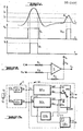
- FIG. 2 represents a conventional threshold switching circuit capable of receiving the analog signal of FIG. 1 and transforming it into one of the two pulses with steep edges Vb or Vh.
- This switching circuit consists of a differential amplifier 11 with very large gain in open loop, very conventionally connected to the resistors R 1 , R 2 , R 3 and R 4 .
- the analog signal is applied to the input E at the free terminal of the resistor R l and a reference voltage (of value h or b depending on whether the switching circuit is set on the high; or low threshold) is permanently applied at the Ref input, at the free terminal of the resistor R 2 .
- the Vb or Vh pulse is available at output S 0 .
- the differential amplifier 11 Given its significant gain, the differential amplifier 11 is always in its blocked state or in its saturated state, depending on whether the value of the analog signal is greater or less than the value of the threshold h or b chosen and applied to the input. Ref. It will be noted that given the form of the analog signal (or more exactly of its usable positive central part) the lower the chosen threshold, the longer the duration of the resulting steep edge pulse.
- a chain of recognition associated with the low threshold is necessarily the corresponding switching circuit provides "wide" pulses more easily processed by the digital logic circuits which make up the character recognition chain connected to this switching circuit.
- the digital logic circuits which make up the character recognition chain connected to this switching circuit.
- Figure 3 illustrates the system in its most general principle.
- a read head 12 has an analog signal output 13 connected to the two inputs EOb and EOh of the two threshold switching circuits SEb and SEh respective of the analog-digital conversion circuit C; the circuit SEb being adjusted with the low threshold and the circuit SEh being adjusted with the high threshold, according to the above.
- the respective outputs of these circuits SEb and SEh will be called Sb and Sh.
- the system of FIG. 3 imperatively includes a pulse signal output for each predetermined length of the character coding.
- n 2
- the internal arrangement of the recognition circuit 14 depends, of course, on the reading principle adopted, which can be, among other things, one of the three reading modes which have been briefly described above.
- the multiplexer MX is arranged to selectively correspond to the outputs SL, SC, either the inputs Ebl, Ebc, connected to the recognition chain REb (associated with the lowest threshold) or the inputs Ehl, Ehc connected to the recognition chain REh (associated with the the highest threshold).
- the transition is ensured by control means reacting to a control signal generated by the ERb circuit connected to the COM input of the MX multiplexer.
- the ERb circuit determines whether the ERb circuit signals an error or not. If the ERb circuit signals an error, a control pulse is applied to the COM input which activates the means for controlling the multiplexer. The latter then matches the inputs Ehl, Ehc with the outputs SL, SC, respectively. If the ERh circuit does not detect any identification error on the recognition chain REh (case illustrated in FIG. 1), the reading is considered to be correct and everything happens as if the system had corrected itself and its error automatically. reading. On the other hand, if the error remains, the ERh circuit can be connected to a output E R to transmit a signal capable of being taken into account by a character processing and identification unit (not shown) connected downstream of the system described in FIG. 3, that is to say in fact connected to receive at least the signals appearing at the outputs SL, SC and ER.
- a character processing and identification unit not shown
- FIG. 3 is only a system for reading and not for complete identification of the characters.
- the processing and identification unit mentioned above is designed to determine which character has been read from the order in which the pulses appear at the outputs SL and SC. Thus, we recall that for the digit O, there will be successively two pulses at the output SC then two pulses at the output SL and finally two pulses at the output SC.
- Other means, not described in FIG. 3, allow said processing and identification unit to recognize the beginning and the end of reading a character (very long interval in the case of the CMC7 code).
- the processing and identification unit If a signal is transmitted to the ER output during the reading of a character, the processing and identification unit "will know” whereas an anomaly during the reading of this character could not be corrected; since the error signal was generated by the error detection circuit connected to the recognition chain REh associated with the highest threshold.
- the processing and identification unit can then be programmed to send a "non-recognition signal" of a read character, signaling the anomaly to an operator.
- the ER output can easily be deleted if it is desirable to limit the number of connections between the reading system described and the aforementioned processing and identification unit. For this, it suffices to provide forcing means F associated with the circuit ERh and connected to the multiplexer MX. This variant is illustrated by the broken lines in FIG. 3.
- the processing and identification unit is programmed to interpret the order of succession of the pulses which appear at the outputs SL and SC. It is therefore easy to complete this unit to make it interpret the simultaneity of two pulses at the outputs SL and SC as an error (because an interval read cannot be both long and short).
- the "intelligence" of the processing and identification unit could be summarized by the following Table of Truth:
- the forcing means F are activated by the circuit ERh to apply two pulses simultaneously with the outputs SL and SC, in the event of a reading error which cannot be corrected automatically, the output ER can advantageously be suppressed.
- FIG. 4 more particularly describes a reading system using a double reading head with two magneto-resistance sensors spaced apart by a distance e verifying the relationship:
- the reading system of Figure 3 operates according to the third reading mode described above.
- the first sensor or sensor A will be indifferently called the one which is arranged to read the first the presence of a magnetized segment during the useful relative movement between the read head and the document, and the second sensor or sensor B l 'other sensor reading the same information as sensor A but shifted in time because of the spacing e (400 ⁇ m in the case of code CMC7) between the two sensors.
- circuit elements receiving signals from the first sensor will carry the letter-index:: A in their reference while the circuit elements receiving signals from the second sensor will carry the letter-index B in their reference (just as we previously indicated a correlation of a circuit with a high or low threshold by an index letter h or b, respectively).
- the system of FIG. 4 will comprise two analog-digital conversion circuits Cb and Ch each comprising two threshold switching circuits.
- the circuits SEAb, SEBb which are connected to the inputs EAb, EBb of the recognition chain REb associated with the low threshold and the circuits SEAh, SEBh which are connected to the inputs EAh, EBh of the recognition chain REh associated with the high threshold .
- the analog signal output SA of sensor A is connected to inputs EOAb and EOAh of circuits SEAb and SEAh while the analog signal output SB of sensor B is connected to inputs EOBb and EO Bh of circuits SEBb and SEBh.
- the recognition chain REb has two inputs EAb and EBb connected respectively to the outputs SAb and SBb of the SEAb and SEBb circuits.
- the recognition chain REh comprises two inputs EAh and EBh connected respectively to the outputs SAh and SBh of the circuits SEAh and SEBh.
- the recognition chain REb first comprises a "means forming a monostable sensitive to a rising edge” MObl, that is to say arranged to be activated on each rising edge of its input signal and a “means forming a monostable sensitive to a falling edge "MOb2, that is to say arranged to be activated at each falling edge of its input signal.
- MObl a monostable sensitive to a rising edge
- MOb2 a monostable sensitive to a falling edge
- the monostable MObl will provide a significant output signal for each rising edge of each pulse generated by the circuit SEAb while the monostable MOb2 will provide a significant output signal for each falling edge of each pulse generated by the circuit SEAb.
- the output of the monostable MObl is connected to an input of a first combinative circuit Cbl, another input of which is connected to the input EBb (to receive the signal generated by the circuit SEBb).
- the output of the monostable MOb2 is connected to an input of a second combinational circuit Cb2, another input of which is connected to the input EBb.
- “Combinatorial circuit” means any logic gate or gate circuit arranged to produce the logic product ("as opposed to the logic sum") of the input signals.
- each combinational circuit has been symbolized by an AND gate (but one could also use a NAND gate).
- the combinational circuit Cbl is arranged to provide a significant output signal when a signal from the first monostable means MObl occurs during the duration of a pulse generated by the threshold switching circuit SEBb, associated with the sensor B.
- the combinational circuit Cb2 is arranged to supply a significant output signal when a signal from the second monostable means MOb2 occurs during the duration of a pulse generated by the threshold switching circuit SEBb.
- the outputs of the combinative circuits Cbl and Cb2 are respectively connected to the inputs of a first and of a second means forming memory JKbl and JKbc (since in practice they can be simple flip-flops JK) so that said "signals of significant outputs "of the circuits Cbl and Cb2 are immediately memorized and appear at the outputs Sbl and Sbc connected respectively to the outputs of the memories JKbl and JKbc.
- a shift register RDAb is used, the signal input of which is connected to the input EAb (to receive the pulses generated by the low threshold switching circuit SEAb connected to the first sensor A).
- An input H of the shift register receives a clock signal with relatively frequency high.
- the register also comprises a certain number of outputs sl, s2, s3, s4.
- a pulse applied to the input EAb will be transmitted to the output sl with a delay 1H (delay of a clock pulse), at the output s2 with a delay 2H, at the output s3 with a delay 3H ...
- the output sl is connected to an input of an AND gate with two inputs, Gl (or a NAND gate with two inputs) and the output s2 is connected to the second input of this same door through a NO door, G2.
- the signal available at the output sl conforms to the logic condition:
- FIG. 5a It can be seen in FIG. 5a that it is a pulse of duration 1H coinciding substantially in time with the rising edge of the signal applied to the input EAb.
- a “monostable sensitive to the rising edge” function has therefore been achieved since an output of a fixed duration pulse of value 1H (monostable) coinciding with the rising edge of the input signal is obtained at the output.
- the additional AND gate is G3 and its output is S2.
- the additional NON gate is G4; its input is connected to the output sl and its output to an input of the gate G3.
- the other input of gate G3 is directly connected to output S2.
- FIG. 8 shows an additional shift register RDBb which can be interconnected between the input EBb and said third inputs of the gates G'l, G'3 to delay the signal coming from the sensor B by a value of 1H.
- said third inputs of the doors G'1 and G'3 are connected to the output s'1 of the shift register.
- This shift register can also be usefully used to generate synchronization and reset signals for the entire system.
- the output ECH that is to say the output of the gate G5
- G5 can constitute an output of the reading system according to the invention, in the same way as the outputs SL and SC, if the processing unit and d he identification mentioned above is designed to receive the corresponding signals so as to take into account the signals transmitted to the outputs SL and / or SC only at the moment when a pulse is transmitted to the output ECH.
- the reset signal is obtained thanks to an AND gate G7 (or a NAND gate) of which an input is connected to the output s'3 via a gate NON G3 and the other input of which is directly connected to output s'4 of the shift register RDBb.
- G7 or a NAND gate
- each flip-flop JKbl, JKbc, JKhl, JKhc has a reset input (not shown) connected to the reset output of FIG. 8.
- the first type of error is equivalent to detecting the logical condition: Sbl. Sbc on the recognition chain REb associated with the low threshold or the logic condition Shl. Shc on the REh recognition chain associated with the high threshold.
- the second case is equivalent to the logical condition Sbl.S Ab for the recognition chain REb or to the condition Sbh.SAh for the recognition chain REh.
- the ERb error detection circuit could for example conform to the diagram in FIG. 11.
- An AND gate (or a NAND gate) G10 at one of its inputs connected to a complemented output Sbl of the Sbl output and its other input to the sl output (that is to say, to the delayed SAb output of 1H) while another door of the same type, Gll, has its two inputs connected to the two outputs Sbl and Sbc of the recognition chain REb.
- the outputs of these gates are connected to the two inputs of a G12 gate of the OR type or of the NON-OR type, the output of which is connected to the COM input of the MX multiplexer.
- Another type of error which is more particularly interesting to take into account when it persists on the recognition chain REh, corresponds to the case where none of the flip-flops JKhl and JKhc changed state at the end of the signal generated by the SEbh circuit (that is to say at the moment when a pulse appears at the output ECH, which normally would mean the reading of a very long interval) but that during this time a signal is actually present at the SAb output (or at the sl output of the shift register RDAb) which can only be an error.
- the processing and identification unit does not interpret the signals transmitted to it as an "end of character" when it is indeed a reading error
- the ERh circuit is designed to detect the condition:
- FIG. 12 shows a possible embodiment of the error detection circuit ERh associated with means forcing F.
- the AND gate (or a NAND gate) G13 plays exactly the same detection role as the gate G10 in FIG. 11.
- the AND gate (or NON-AND) G14 has three inputs, two of which are connected to complementary outputs (Shl and Shc) of the outputs of the recognition chain REh and whose third input is connected to the output SAb of the circuit SEAb consequently receiving signals from the sensor A.
- the outputs of the doors G13 and G14 are respectively connected to the two inputs of an OR gate (or a NOR gate) G15 and the output of this gate in fact constitutes the signal output of the ERh circuit.
- the forcing circuit F is itself made up of two OR gates (or NOR gates) G16, G17 with two inputs, two respective inputs of which are connected to the output of the ERh circuit and the other two inputs of which are respectively connected to the signal outputs from the REh recognition chain.
- the outputs of doors G16 and G17 are connected respectively to the inputs Ehl and Ehc of the MX multiplexer. If we refer to FIG. 3, we therefore see that the embodiment of the forcing circuit F represented in FIG. 12 is in fact intended to be interconnected between the outputs of the recognition chain REh and the inputs Ehc, Ehl of the multiplexer MX.
- the forcing circuit F controlled by the circuit ERh will act on the multiplexer MX to transmit signals simultaneously to the two outputs SL and SC which will be interpreted as an error by the processing and recognition unit.
Abstract
Pour la reconnaissance de caractère en code CMC-7, une tête de lecture (12) fournit un signal analogique à deux discriminateurs de niveau (SEb et SEh) à seuils différents. Deux chaines de traitement (REb et REh) reçoivent chacune le signal d'un des deux discriminateurs de niveau et délivrent des signaux représentatifs des intervalles courts ou longs du caractère codé. Un multiplexeur (MX) permet de choisir l'un ou l'autre des groupes de sortie des deux chaînes de traitement, en fonction de l'état de deux circuits de détection d'erreur (ERb er ERh). En l'absence d'erreur, le multiplexeur choisit la chaîne de traitement reliée au discriminateur de niveau au seuil le plus bas (SEb). En cas d'erreur, le signal de l'autre chaîne est transmis par le multiplexeur. Extension à un dispositif à deux têtes de lectures avec quatre chaînes de traitement.For character recognition in CMC-7 code, a read head (12) supplies an analog signal to two level discriminators (SEb and SEh) with different thresholds. Two processing chains (REb and REh) each receive the signal from one of the two level discriminators and deliver signals representative of the short or long intervals of the coded character. A multiplexer (MX) makes it possible to choose one or the other of the output groups of the two processing chains, depending on the state of two error detection circuits (ERb and ERh). In the absence of error, the multiplexer chooses the processing chain linked to the level discriminator at the lowest threshold (SEb). In the event of an error, the signal from the other channel is transmitted by the multiplexer. Extension to a device with two read heads with four processing chains.
Description
L'invention concerne un système de lecture de caractères codés et matérialisés sur un document par une succession de groupements de segments séparés entre eux par des intervalles choisis dans un ensemble de plusieurs longueurs prédéterminées. Le but de l'invention est de proposer un système susceptible de corriger automatiquement certaines erreurs de lecture résultant notamment de défauts sur le document, rendant sa lecture par des moyens électroniques, difficile. L'invention s'applique notamment mais non exclusivement à la lecture des caractères imprimés dans le code désigné par le sigle CMC7 (Caractère Magnétique Codé à sept éléments) largement utilisé en Europe par les Etablissements Financiers pour inscrire sur leurs formules de chèque les références principales, telles que le numéro de code de la Succursale émettrice, celui du compte du titulaire, etc...The invention relates to a system for reading coded characters materialized on a document by a succession of groupings of segments separated from one another by intervals chosen from a set of several predetermined lengths. The object of the invention is to propose a system capable of automatically correcting certain reading errors resulting in particular from faults on the document, making it difficult to read by electronic means. The invention applies in particular but not exclusively to the reading of the characters printed in the code designated by the acronym CMC7 (Magnetic Character Coded with seven elements) widely used in Europe by Financial Institutions to write the main references on their check formulas , such as the issuing branch code number, the holder's account number, etc.
Sur certains documents, des caractères spéciaux sont matérialisés (notamment imprimés au moyen d'une encre spéciale, par exemple magnétisable) pour pouvoir être lus automatiquement par des moyens électroniques. Ainsi, on utilise couramment des caractères formés par une succession de groupements de segments séparés entre eux par des intervalles choisis dans un ensemble de n longueurs prédéterminées. D'autre part, chaque caractère défini par un nombre constant d'intervalles choisis dans les n longueurs est séparé de son voisin par un intervalle plus long que le plus grand des n intervalles.On certain documents, special characters are materialized (in particular printed using a special ink, for example magnetizable) to be able to be read automatically by electronic means. So, we commonly use characters formed by a succession of groupings of segments separated from each other by intervals chosen from a set of n predetermined lengths. On the other hand, each character defined by a constant number of intervals chosen from the n lengths is separated from its neighbor by an interval longer than the largest of the n intervals.
Comme mentionné précédemment, le plus utilisé de ces codes est couramment désigné par le sigle CMC7. Ce code est susceptible de représenter des caractères alphanumériques qui présentent l'avantage de pouvoir aussi bien être lus par une machine (par détection d'un champ magnétique) que par un individu, puisque le caractère alphanumérique peut apparaître sur le document sous forme légèrement "hachée" mais néanmoins bien lisible. Plus le chiffre n est grand, plus on peut coder de caractères différents. Ainsi, pour le code CMC7, c'est-à-dire plus précisément le code numérique limité à 15 caractères (lO chiffres et 5 symboles spéciaux) employé dans le traitement des chèques il y a 7 segments définissant 6 intervalles parmi lesquels il doit y avoir 2 intervalles longs et 4 intervalles courts. Les différentes combinaisons possible de l'ordre de succession de ces intervalles courts et longs permettent de différencier les caractères. Ainsi, on rappellera que dans ce code CMC7, le chiffre 0 est défini par, successivement de la gauche vers la droite, deux intervalles courts, deux intervalles longs et deux : intervalles courts ; le chiffre 1 est défini par un : intervalle long, trois intervalles courts, un intervalle long et un intervalle court ; le chiffre 2 est défini par un intervalle court, deux intervalles longs et trois intervalles courts ; etc... Les valeurs normalisées des intervalles sont définies comme suit :
- - entraxe de deux segments séparés par un espace court (intervalle court)

- - entraxe de deux segments separés par un espace long (intervalle long)

- - largeur d'un segment

- - valeur de l'intervalle très long (entre deux caractères successifs)

- - distance between two segments separated by a short space (short interval)
- - distance between two segments separated by a long space (long interval)
- - width of a segment
- - value of the very long interval (between two successive characters)
Le plus souvent, les segments, espacés des intervalles précités, sont imprimés avec une encre magnétisable.Most often, the segments, spaced from the aforementioned intervals, are printed with a magnetizable ink.
On connait plusieurs modes de lecture de ces caractères codés.Several modes of reading these coded characters are known.
Le premier mode de lecture consiste à faire défiler le document devant une unique tête de lecture et à mesurer les intervalles de temps séparant le passage de deux segments successifs devant l'entrefer de cette tête de lecture. Le système a donc l'inconvénient majeur d'exiger une stabilisation parfaite de la vitesse de défilement.The first reading mode consists in scrolling the document in front of a single reading head and in measuring the time intervals separating the passage of two successive segments in front of the air gap of this reading head. The system therefore has the major drawback of requiring perfect stabilization of the running speed.
Un second mode de lecture, décrit en particulier dans le brevet français n° 2 289 010 intitulé "Dispositif de lecture d'une information", permet de différencier les intervalles courts et longs en utilisant deux têtes de lecture (ou une tête de lecture double à deux capteurs) décalées d'une distance égale à l'un des intervalles. On détecte alors la simultanéité ou la non simultanéité de passage des segments devant les deux têtes, pour différencier un intervalle long d'un intervalle court. En outre, pour pouvoir sans inconvénients réduire la vitesse de défilement, le dispositif décrit dans ce brevet utilise des capteurs réalisés avec des magnéto-résistances sensibles à l'intensité du champ magnétique reçu et non à sa variation. Des lecteurs à magnéto-résistances sont décrits dans les demandes de brevets n° 77 13 026 et 77 14 661 déposées au nom de la demanderesse. Cependant, dans le cas du code CMC7, on ne peut reconnaitre l'intervalle très long avec deux magnéto-résistances.A second reading mode, described in particular in French patent No. 2,289,010 entitled "Device for reading information", makes it possible to differentiate between short and long intervals by using two read heads (or a double read head two sensors) offset by a distance equal to one of the intervals. We then detect the simultaneity or non-simultaneity of passage of the segments in front of the two heads, to differentiate a long interval from a short interval. In addition, in order to be able to reduce the running speed without drawbacks, the device described in this patent uses sensors produced with magneto-resistors sensitive to the intensity of the magnetic field received and not to its variation. Magneto-resistance readers are described in patent applications Nos. 77 13 026 and 77 14 661 filed in the name of the applicant. However, in the case of the CMC7 code, the very long interval cannot be recognized with two magnetoresistors.
Enfin, un troisième mode de lecture est décrit plus particulièrement dans la demande de brevet français n° 77 39 749 déposée au nom de la demanderesse. Il consiste à utiliser (pour le code CMC7) deux magnéto-résistances séparées d'une distance e (entraxe) vérifiant la double inégalité :
Le principal avantage de ce troisième mode de lecture par rapport au second est de permettre la différenciation de l'intervalle très long à partir de seulement deux capteurs à magnéto-résistance séparés par la distance e. Toujours dans le cadre du code CMC7, et si on appelle "premier capteur" celui qui est disposé pour lire le premier la présence d'un segment magnétique pendant le mouvement relatif de lecture entre le document et lesdits capteurs et "second capteur" celui qui est disposé pour lire la même information mais en second lieu, la règle de reconnaissance des différents intervalles est la suivante :
- 1) un intervalle long est détecté lorsqu'on enregistre un front montant d'une impulsion engendrée à partir du premier capteur pendant la présence d'une impulsion engendrée à partir du second capteur,
- 2) un intervalle court est détecté lorsqu'on enregistre un front descendant d'une impulsion engendrée à partir du premier capteur pendant la présence d'une impulsion engendrée à partir du second capteur,
- 3) un intervalle très long est détecté lorsqu'aucune impulsion n'est engendrée à partir du premier capteur pendant la présence d'une impulsion engendrée à partir du second capteur.
- 1) a long interval is detected when a rising edge of a pulse generated from the first sensor is recorded during the presence of a pulse generated from the second sensor,
- 2) a short interval is detected when a falling edge of a pulse generated from the first sensor is recorded during the presence of a pulse generated from the second sensor,
- 3) a very long interval is detected when no pulse is generated from the first sensor during the presence of a pulse generated from the second sensor.
La demande de brevet n° 77 39 749 indiquée ci-dessus montre en outre comment généraliser le principe à la différenciation d'un plus grand nombre d'intervalles avec un plus grand nombre de capteurs à magnéto-résistance.Patent application No. 77 39 749 indicated above also shows how to generalize the principle to the differentiation of a greater number of intervals with a greater number of magneto-resistance sensors.
Cependant, pour les trois modes de lecture signalés ci-dessus, entre autre, des erreurs de lecture sont possibles. Elles sont essentiellement dues, soit à des imperfections dans l'impression des caractères (défauts d'encrage ou au contraire présence de taches minuscules pouvant être interprétées comme des segments supplémentaires par le système de lecture) soit à une détérioration du support ayant entrainé de tels défauts dans l'impression des caractères. Il ne faut pas oublier en effet qu'un chèque, par exemple, est souvent froissé ou au moins plié lorsqu'il est présenté à l'encaissement.However, for the three reading modes indicated above, among others, reading errors are possible. They are essentially due either to imperfections in the printing of the characters (defects in inking or on the contrary presence of tiny spots which can be interpreted as additional segments by the reading system) or to a deterioration of the support having led to such defects in printing characters. It should not be forgotten that a check, for example, is often crumpled or at least folded when presented for collection.
La présente invention a pour objet un système de lecture à haute performance capable à la fois de détecter la plupart des erreurs de lecture, de corriger automatiquement certaines d'entre elles ou au moins de signaler la présence d'une erreur de lecture non corrigeable automatiquement. En outre, le principe général de l'invention est non seulement applicable aux trois modes de lecture brièvement décrits ci-dessus, utilisant des têtes de lecture à magnéto-résistance ou non, mais il est aisément adaptable à d'autres moyens de codage non magnétiques, c'est-à-dire mettant en jeu d'autres phénomènes physiques (électriques, opto- électriques, etc...).The present invention relates to a high performance reading system capable of both detecting most reading errors, automatically correcting some of them or at least signaling the presence of a reading error which cannot be corrected automatically. . In addition, the general principle of the invention is not only applicable to the three reading modes briefly described above, using reading heads with or without magneto-resistance, but it is easily adaptable to other non-coding means. magnetic, that is to say involving other physical phenomena (electric, opto-electric, etc ...).
En bref, la caractéristique fondamentale de l'invention réside dans le fait qu'on prévoit plusieurs chaînes de reconnaissance distinctes recevant les signaux en provenance du ou des capteurs de la tête de lecture, par l'intermédiaire de moyens de conversion analogique-numérique composés de plusieurs circuits de commutation à seuil ayant des valeurs de seuil respectives différentes, et qu'on prévoit des moyens de détection d'erreur associé à chaque chaine de reconnaissance pour ne prendre en considération que les signaux émis par la première chaine de reconnaissance sur laquelle les moyens de détection d'erreur correspondants ne détectent pas d'erreur de lecture, en partant de la chaîne de reconnaissance associée au seuil le plus bas (donc la plus sensible) jusqu'à la chaîne de reconnaissance associée au seuil le plus haut (la moins sensible) ; lesdites chaînes de reconnaissance étant classées par ordre croissant desdits seuils.In short, the fundamental characteristic of the invention resides in the fact that several distinct recognition chains are provided, receiving the signals coming from the sensor (s) of the read head, by means of analog-to-digital conversion means of several threshold switching circuits having different respective threshold values, and provision is made for error detection means associated with each recognition chain so as to take into consideration only the signals transmitted by the first recognition chain on which the corresponding error detection means do not detect a reading error, starting from the recognition chain associated with the lowest threshold (therefore the most sensitive) to the recognition chain associated with the highest threshold ( least sensitive); said recognition chains being classified in ascending order of said thresholds.
Plus précisément, l'invention concerne donc un système de lecture de caractères codés et matérisalisés sur un document par des successions de groupements de segments de largeur constante, alignés le long d'un trajet de lecture et séparés entre eux, pour définir un caractère donné, par des intervalles choisis dans un ensemble de n longueurs prédéterminées et reconnaissables électroniquement par détection d'un phénomène physique, notamment magnétique, par un type de capteur approprié; du type comportant au moins une tête de lecture incluant au moins un capteur précité disposé en regard dudit trajet de lecture ainsi qu'un moyen d'entrainement assurant un mouvement relatif entre ladite tête de lecture et ledit document, ladite tête de lecture comportant au moins une sortie de signal analogique représentatif desdits intervalles lus par ledit capteur ; ce système comportant en outre une sortie de signal impulsionnel pour chaque longueur prédéterminée, un circuit de conversion analogique-numérique relié à ladite sortie de signal analogique et un circuit logique de reconnaissance desdits intervalles interconnecté entre ledit circuit de conversion et lesdites sorties de signal impulsionnel ; caractérisé en ce que ledit circuit de conversion comporte m circuits de commutation à seuil ayant des valeurs de seuil respectives différentes, et en ce que ledit circuit de reconnaissance desdits intervalles se compose essentiellement de :
- - m chaînes de reconnaissance distinctes (m entier supérieur à 1) connectées chacune à la sortie d'un circuit de commutation à seuil précité et comportant chacune un groupe de n sotties correspondant aux n longueurs d'intervalle précitées
- - un circuit de sélection à m positions comportant n sorties reliées respectivement aux sorties de signal impulsionnel pour chaque longueur prédéterminée précitée et m groupes de n entrées reliés chacun et respectivement à un groupe de n sorties des m chaînes de reconnaissance, et comportant également des moyens de pilotage permettant de faire correspondre sélectivement les n entrées de l'un des m groupes aux n sorties dudit circuit de sélection dans un ordre de succession prédéterminé allant du groupe relié à la chaîne de reconnaissance associée au seuil le plus bas jusqu'au groupe relié à la chaîne de reconnaissance associée au seuil le plus haut et classés par ordre croissant desdits seuils, et
- - des moyens de détection d'erreur d'identification opérativement couplés auxdits moyens de pilotage pour activer ces derniers à provoquer et poursuivre l'ordre de succession prédéterminé précité tant qu'une erreur est détectée dans les signaux transmis par une chaîne de reconnaissance dont les sorties sont actuellement couplées aux sorties dudit circuit de sélection.
- - m separate recognition chains (m integer greater than 1) each connected to the output of a switching circuit with aforementioned threshold and comprising each a group of n sotties corresponding to the n above-mentioned interval lengths
- a selection circuit with m positions comprising n outputs connected respectively to the pulse signal outputs for each aforementioned predetermined length and m groups of n inputs each connected respectively to a group of n outputs of the m recognition chains, and also comprising means control allowing to selectively correspond the n inputs of one of the m groups to the n outputs of said selection circuit in a predetermined order of succession going from the group connected to the recognition chain associated with the lowest threshold to the connected group the recognition chain associated with the highest threshold and ranked in ascending order of said thresholds, and
- - identification error detection means operatively coupled to said control means to activate the latter to cause and continue the aforementioned predetermined order of succession as long as an error is detected in the signals transmitted by a recognition chain, the outputs are currently coupled to the outputs of said selection circuit.
Bien entendu, dans le cas du code CMC7, on a n = 2 puisque d'après la définition qui précède, l'intervalle très long défini précédemment n'intervient pas pour définir un caractère donné mais simplement pour signaler la lecture du caractère suivant. Par ailleurs, dans tous les exemples de réalisation qui seront décrits plus en détail ci-après, on a choisi m = 2, ce qui en clair signifie que chaque circuit de conversion analogique-numérique comporte un circuit de commutation à seuil bas et un circuit de commutation à seuil haut. En revanche, l'un des exemples de réalisation se rapporte plus spécifiquement au troisième mode de lecture évoqué précédemment ; c'est-à-dire avec une double tête de lecture comportant en fait deux capteurs à magnéto-résistance. Dans ce cas, la tête de lecture comportera donc. deux sorties de signal analogique distinctes transmettant le signal de chaque capteur et chaque sortie de signal analogique sera reliée à deux circuits de commutation à seuil (m = 2). On aura donc au total quatre circuits de commutation à seuil dont deux réglés sur le seuil bas et deux réglés sur le seuil haut.Of course, in the case of the CMC7 code, we have an = 2 since, according to the preceding definition, the very long interval defined previously does not intervene to define a given character but simply to signal the reading of the next character. Furthermore, in all the exemplary embodiments which will be described in more detail below, we have chosen m = 2, which clearly means that each conversion circuit analog-digital includes a low threshold switching circuit and a high threshold switching circuit. On the other hand, one of the exemplary embodiments relates more specifically to the third reading mode mentioned above; that is to say with a double read head actually comprising two magneto-resistance sensors. In this case, the read head will therefore comprise. two separate analog signal outputs transmitting the signal from each sensor and each analog signal output will be connected to two threshold switching circuits (m = 2). There will therefore be a total of four threshold switching circuits, two of which are set on the low threshold and two of which are set on the high threshold.
L'invention sera mieux comprise et d'autres buts, détails et avantages de celle-ci apparaitront mieux à la lumière de la description explicative qui va suivre de plusieurs modes de réalisation du système selon l'invention donnée uniquement à titre d'exemple et faite en référence aux dessins non limitatifs annexés dans lesquels :
- - la figure 1 représente un chronogramme montrant les caractéristiques des signaux engendrés par des circuits de commutation à seuils différents, à partir du même signal analogique ;
- - la figure 2 est un exemple de circuit de commutation à seuil utilisable dans le cadre de l'invention ;
- - la figure 3 représente un schéma-bloc d'un système de lecture selon l'invention, avec une seule tête de lecture à capteur unique, fonctionnant par détection d'un phénomène physique quelconque, pour n = 2 (par exemple le code CMC7) et m = 2 ;
- - la figure 4 représente une variante d'une partie du circuit de la figure 3, pour une tête de lecture double comportant par exemple deux capteurs à magnéto-résitance espacés entre eux d'une distance e vérifiant la double inégalité indiquée ci-dessus ;
- - la figure 5 représente un mode de réalisation avantageux d'un moyen formant monostable sensible au front montant du signal d'entrée ;
- - la figure 5a est un chronogramme expliquant le fonctionnement du circuit de la figure 5 ;
- - la figure 6 est un schéma montrant une combinaison d'un moyen formant monostable sensible au front montant et d'un moyen formant monostable sensible au front descendant du signal d'entrée ;
- - la figure 7 est un schéma montrant une combinaison du circuit de la figure 6 avec les circuits combinatoires représentés à la figure 4 ;
- - la figure 8 est un schéma montrant les circuits d'élaboration des signaux d'échantillonnage (ou de validation) et des signaux de remise à zéro du système selon l'invention ;
- - les figures 9 et 10 sont des chronogrammes montrant les différents types d'anomalies détectables par le système ;
- - la figure 11 illustre un mode de réalisation du circuit ERb de la figure 3 ; et
- - la figure 12 illustre un mode de réalisation des circuits ERh et F de la figure 3.
- - Figure 1 shows a timing diagram showing the characteristics of the signals generated by switching circuits with different thresholds, from the same analog signal;
- - Figure 2 is an example of threshold switching circuit usable in the context of the invention;
- - Figure 3 shows a block diagram of a reading system according to the invention, with a single reading head with single sensor, operating by detection any physical phenomenon, for n = 2 (for example the code CMC7) and m = 2;
- - Figure 4 shows a variant of part of the circuit of Figure 3, for a double read head comprising for example two magneto-resistance sensors spaced apart by a distance e verifying the double inequality indicated above;
- - Figure 5 shows an advantageous embodiment of a monostable forming means sensitive to the rising edge of the input signal;
- - Figure 5a is a timing diagram explaining the operation of the circuit of Figure 5;
- - Figure 6 is a diagram showing a combination of a monostable means sensitive to the rising edge and a monostable means sensitive to the falling edge of the input signal;
- - Figure 7 is a diagram showing a combination of the circuit of Figure 6 with the combinational circuits shown in Figure 4;
- - Figure 8 is a diagram showing the circuits for developing the sampling signals (or validation) and reset signals of the system according to the invention;
- - Figures 9 and 10 are timing diagrams showing the different types of anomalies detectable by the system;
- - Figure 11 illustrates an embodiment of the ERb circuit of Figure 3; and
- FIG. 12 illustrates an embodiment of the circuits ERh and F of FIG. 3.
En se référant à la figure 1, on a représenté une forme de signal analogique conforme à la réponse d'un capteur à magnéto-résistance (non représenté) lorsqu'un segment magnétisé du document passe à proximité dudit capteur. La figure 2 représente un circuit de commutation à seuil, classique, pouvant recevoir le signal analogique de la figure 1 et le transformer en l'une des deux impulsions à fronts raides Vb ou Vh. Ce circuit de commutation se compose d'un amplificateur différentiel 11 à très grand gain en boucle ouverte, connecté de façon très classique aux résistances R1, R2, R3 et R4. Le signal analogique est appliqué à l'entrée E à la borne libre de la résistance Rl et une tension de référence (de valeur h ou b suivant que le circuit de commutation est réglé sur le seuil haut; ou bas) est appliqué en permanence à l'entrée Ref, à la borne libre de la résistance R2. L'impulsion Vb ou Vh est disponible à la sortie S0. Etant donné son gain important, l'amplificateur différentiel 11 se trouve toujours dans son état bloqué ou dans son état saturé, suivant que la valeur du signal analogique est supérieure ou inférieure à la valeur du seuil h ou b choisi et appliqué à l'entrée Ref. On notera qu'étant donnée la forme du signal analogique (ou plus exactement de sa partie centrale positive utilisable) plus le seuil choisi est bas, plus la durée de l'impulsion à fronts raides résultante est longue. Autrement dit, une chaîne de reconnaissance associée au seuil bas est nécessairement la ![]()
![]()
La figure 3 illustre le système dans son principe le plus général. Une tête de lecture 12 comporte une sortie de signal analogique 13 reliée aux deux entrées EOb et EOh des deux circuits de commutation à seuil SEb et SEh respectifs du circuit de conversion analogique-numérique C ; le circuit SEb étant réglé avec le seuil bas et le circuit SEh étant réglé avec le seuil haut, selon ce qui précède. Les sorties respectives de ces circuits SEb et SEh seront appelées Sb et Sh. Outre le circuit Z, le système de la figure 3 comporte impérativement une sortie de signal impulsionnel pour chaque longueur prédéterminée du codage de caractère. Dans l'exemple décrit, comme n = 2, il y a donc au moins deux sorties SL et SC sur lesquelles doivent apparaître les impulsions lorsqu'un intervalle long ou un intervalle court, respectivement, a été identifié par un circuit de reconnaissance 14 de ces intervalles, lequel est interconnecté entre le circuit C et les deux sorties SL et SC. L'agencement interne du circuit de reconnaissance 14 dépend bien entendu, du principe de lecture retenu, qui peut être, entre autre, l'un des trois modes de lecture qui ont été décrits brièvement ci-dessus. Il comporte néanmoins obligatoirement deux chaînes de reconnaissance distinctes (m = 2) REb et REh dont les entrées respectives Eb et Eh sont reliées aux sorties Sb et Sh des circuits de commutation à seuil SEb, SEh, respectivement, ainsi que deux circuits de détection d'erreur ERb et ERh et un circuit de sélection MX (essentiellement constitué d'un multiplexeur à m voies). Les deux circuits de détection d'erreur ERb et ERh sont reliés respectivement aux chaînes de reconnaissance REb et REh et sont susceptibles de déceler certaines erreurs de lecture transmises sur ces chaînes de reconnaissance. Chaque chaîne de reconnaissance comporte un groupe de deux sorties (n = 2). Ces sorties sont Sbl, Sbc pour la chaîne de reconnaissance REb et Shl, Shc pour la chaîne de reconnaissance REh. Ces sorties correspondent aux deux intervalles possibles (long et court) du code et on comprend que les chaînes de reconnaissance sont agencées pour transmettre séquentiellement des impulsions aux sorties correspondantes, selon qu'un intervalle long ou court a été identifié. Par ailleurs,Figure 3 illustrates the system in its most general principle. A read
le multiplexeur MX est à deux positions (m les sorties SL et SC du système sont en faLt également les sorties du multiplexeur. Il comporte deux groupes de deux entrées (m = n = 2) reliés chacun et respectivement à un groupe de deux sorties des deux chaînes de reconnaissance REb et REh. Ainsi, les sorties Sbl et Sbc sont reliées à un premier groupe de deux entrées Ebl et Ebc tandis que les sorties Shl et Shc sont reliées à un second groupe de deux entrées Ehl et Ehc. Le multiplexeur MX est agencé pour faire correspondre sélectivement aux sorties SL, SC, soit les entrées Ebl, Ebc, reliées à la chaîne de reconnaissance REb (associée au seuil le plus bas) soit les entrées Ehl, Ehc reliées à la chaîne de reconnaissance REh (associée au seuil le plus haut). La transition est assurée par des moyens de pilotage réagissant à un signal de commande engendré par le circuit ERb relié à l'entrée COM du multiplexeur MX. Ainsi, lorsqu'aucune erreur d'identification n'est perçue pendant le fonctionnement de la chaîne de reconnaissance REb, le multiplexeur est maintenu dans une première position pour laquelle les entrées Ebl, Ebc correspondent respectivement aux sorties SL, SC. En revanche, si le circuit ERb signale une erreur, une impulsion de commande est appliquée à l'entrée COM qui active les moyens de pilotage du multiplexeur. Ce dernier fait alors correspondre les entrées Ehl, Ehc avec les sorties SL, SC, respectivement. Si le circuit ERh ne détecte aucune erreur d'identification sur la chaîne de reconnaissance REh (cas illustré à la figure 1), la lecture est considérée comme correcte et tout se passe comme si le système avait corrigé lui-même et automatiquement son erreur de lecture. En revanche, si l'erreur subsiste, le circuit ERh peut être relié à une sortie ER pour transmettre un signal susceptible d'être pris en compte par une unité de traitement et d'identification des caractères (non représentée) connectée en aval du système décrit sur la figure 3, c'est-à-dire en fait branchée pour recevoir au moins les signaux apparaissant aux sorties SL, SC et ER.the multiplexer MX has two positions (m the outputs SL and SC of the system are also the outputs of the multiplexer. It has two groups of two inputs (m = n = 2) each connected to a group of two outputs respectively two recognition chains REb and REh. Thus, the outputs Sbl and Sbc are connected to a first group of two inputs Ebl and Ebc while the outputs Shl and Shc are connected to a second group of two inputs Ehl and Ehc. The multiplexer MX is arranged to selectively correspond to the outputs SL, SC, either the inputs Ebl, Ebc, connected to the recognition chain REb (associated with the lowest threshold) or the inputs Ehl, Ehc connected to the recognition chain REh (associated with the the highest threshold). The transition is ensured by control means reacting to a control signal generated by the ERb circuit connected to the COM input of the MX multiplexer. Thus, when no identification error is perceived during how it works nt of the recognition chain REb, the multiplexer is held in a first position for which the inputs Ebl, Ebc correspond respectively to the outputs SL, SC. On the other hand, if the ERb circuit signals an error, a control pulse is applied to the COM input which activates the means for controlling the multiplexer. The latter then matches the inputs Ehl, Ehc with the outputs SL, SC, respectively. If the ERh circuit does not detect any identification error on the recognition chain REh (case illustrated in FIG. 1), the reading is considered to be correct and everything happens as if the system had corrected itself and its error automatically. reading. On the other hand, if the error remains, the ERh circuit can be connected to a output E R to transmit a signal capable of being taken into account by a character processing and identification unit (not shown) connected downstream of the system described in FIG. 3, that is to say in fact connected to receive at least the signals appearing at the outputs SL, SC and ER.
Il est bon en effet de rappeler que le système de la figure 3 n'est qu'un système de lecture et non d'identification complète des caractères. L'unité de traitement et d'identification mentionnée ci-dessus est conçue pour déterminer quel caractère a été lu à partir de l'ordre dans lequel les impulsions apparaissent aux sorties SL et SC. Ainsi, nous rappelons que pour le chiffre O, on aura successivement deux impulsions à la sortie SC puis deux impulsions à la sortie SL et enfin deux impulsions à la sortie SC. D'autres moyens, non décrits sur la figure 3, permettent à ladite unité de traitement et d'identification de reconnaître le début et la fin de la lecture d'un caractère (intervalle très long dans le cas du code CMC7). Si un signal est transmis à la sortie ER pendant la lecture d'un caractère, l'unité de traitement et d'identification "saura" alors qu'une anomalie pendant la lecture de ce caractère n'a pu être corrigée ; puisque le signal d'erreur a été engendré par le circuit de détection d'erreur connecté à la chaîne de reconnaissance REh associée au seuil le plus haut. L'unité de traitement et d'identification pourra alors être programmée pour émettre un "signal de non reconnaissance" d'un caractère lu, signalant l'anomalie à un opérateur. On peut noter également que la sortie ER peut facilement être supprimée s'il est désirable de limiter le nombre de connexions entre le système de lecture décrit et l'unité de traitement et d'identification susmentionnée. Il suffit pour cela de prévoir des moyens de forçage F associés au circuit ERh et connectés au multiplexeur MX. Cette variante est illustrée par les liaisons en traits interrompus sur la figure 3. En effet, on a vu que l'unité de traitement et d'identification est programmée pour interpréter l'ordre de succession des impulsions qui apparaissent aux sorties SL et SC. Il est donc aisé de compléter cette unité pour lui faire interpréter la simultanéité de deux impulsions aux sorties SL et SC comme une erreur (car un intervalle lu ne peut à la fois être long et court). Ainsi, dans le cas du code CMC7, "l'intelligence" de l'unité de traitement et d'identification pourrait être résumée par la Table de Vérité suivante :

Dans ces conditions, si les moyens de forçage F sont activés par le circuit ERh pour appliquer deux impulsions simultanément aux sorties SL et SC, en cas d'erreur de lecture non corrigeable automatiquement, la sortie ER peut être avantageusement supprimée.Under these conditions, if the forcing means F are activated by the circuit ERh to apply two pulses simultaneously with the outputs SL and SC, in the event of a reading error which cannot be corrected automatically, the output ER can advantageously be suppressed.
La généralisation à un système de lecture comportant plus de deux valeurs de seuil (m > 2) peut être aisément déduite de ce qui précède. Il suffirait de prévoir m chaînes de reconnaissance, un multiplexeur à m groupes de n entrées et à m positions ; la position dudit multiplexeur étant déterminée par lesdits moyens de pilotage de ce dernier, activés à partir des (m - 1) circuits de détection d'erreurs sur les (m - 1) chaînes de reconnaissance associées aux (m -1) seuils les plus bas ; pour faire correspondre successivement les m groupes d'entrée aux sorties dudit multiplexeur jusqu'à ce que, éventuellement, le circuit de détection d'erreur sur l'une des chaînes d'identification, associée à un seuil donné, n'enregistre plus d'erreur de lecture ; les signaux transmis par cette chaîne étant alors validés et pris en compte par l'unité de traitement et d'identification. D'autre part, le circuit de détection d'erreur sur la chaîne de reconnaissance associée au seuil le plus haut serait par exemple couplé à des moyens de forçage F du type décrit ci-dessus.The generalization to a reading system comprising more than two threshold values (m> 2) can be easily deduced from the above. It would suffice to provide m recognition chains, a multiplexer with m groups of n inputs and m positions; the position of said multiplexer being determined by said means for controlling the latter, activated from the (m - 1) error detection circuits on the (m - 1) recognition strings associated with the most (m -1) thresholds low; to successively match the m input groups to the outputs of said multiplexer until, if necessary, the error detection circuit on one of the identification chains, associated with a given threshold, no longer records d 'playback error ; the signals transmitted by this chain then being validated and taken into account by the processing and identification unit. On the other hand, the error detection circuit on the recognition chain associated with the highest threshold would, for example, be coupled to forcing means F of the type described above.
La figure 4 décrit plus particulièrement un système de lecture utilisant une tête de lecture double à deux capteurs à magnéto-résistance espacés entre eux d'une distance e vérifiant la relation :
Autrement dit, le système de lecture de la figure 3 fonctionne suivant le troisième mode de lecture décrit plus haut. Dans la suite du texte, on appellera indifféremment premier capteur ou capteur A celui qui est disposé pour lire le premier la présence d'un segment magnétisé lors du mouvement relatif utile entre la tête de lecture et le document, et second capteur ou capteur B l'autre capteur lisant les mêmes informations que le capteur A mais décalées dans le temps à cause de l'espacement e (400 µm dans le cas du code CMC7) entre les deux capteurs. Dans le même ordre d'idée, les éléments de circuit recevant des signaux en provenance du premier capteur porteront la lettre-indice : : A dans leur référence tandis que les éléments de circuit recevant des signaux en provenance du deuxième capteur porteront la lettre-indice B dans leur référence (tout comme on a précédemment indiqué une corrélation d'un circuit avec un seuil haut ou bas par une lettre-indice h ou b, respectivement).In other words, the reading system of Figure 3 operates according to the third reading mode described above. In the following text, the first sensor or sensor A will be indifferently called the one which is arranged to read the first the presence of a magnetized segment during the useful relative movement between the read head and the document, and the second sensor or sensor B l 'other sensor reading the same information as sensor A but shifted in time because of the spacing e (400 µm in the case of code CMC7) between the two sensors. In the same vein, the circuit elements receiving signals from the first sensor will carry the letter-index:: A in their reference while the circuit elements receiving signals from the second sensor will carry the letter-index B in their reference (just as we previously indicated a correlation of a circuit with a high or low threshold by an index letter h or b, respectively).
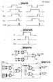
Dans ces conditions, et comme indiqué précédemment, le système de la figure 4 comportera deux circuits de conversion analogique-numérique Cb et Ch comportant chacun deux circuits de commutation à seuil. On a donc les circuits SEAb, SEBb qui sont connectés aux entrées EAb, EBb de la chaîne de reconnaissance REb associé au seuil bas et les circuits SEAh, SEBh qui sont connectés aux entrées EAh, EBh de la chaine de reconnaissance REh associée au seuil haut. La sortie de signal analogique SA du capteur A est reliée aux entrées EOAb et EOAh des circuits SEAb et SEAh tandis que la sortie de signal analogique SB du capteur B est reliée aux entrées EOBb et EOBh des circuits SEBb et SEBh. La chaîne de reconnaissance REb comporte deux entrées EAb et EBb connectées respectivement aux sorties SAb et SBb des circuite SEAb et SEBb. De même, la chaîne de reconnaissance REh comporte deux entrées EAh et EBh connectées respectivement aux sorties SAh et SBh des circuits SEAh et SEBh. On va maintenant décrire plus particulièrement la chaîne de reconnaissance REb ; la chaîne REh ayant la même structure.Under these conditions, and as indicated previously, the system of FIG. 4 will comprise two analog-digital conversion circuits Cb and Ch each comprising two threshold switching circuits. We therefore have the circuits SEAb, SEBb which are connected to the inputs EAb, EBb of the recognition chain REb associated with the low threshold and the circuits SEAh, SEBh which are connected to the inputs EAh, EBh of the recognition chain REh associated with the high threshold . The analog signal output SA of sensor A is connected to inputs EOAb and EOAh of circuits SEAb and SEAh while the analog signal output SB of sensor B is connected to inputs EOBb and EO Bh of circuits SEBb and SEBh. The recognition chain REb has two inputs EAb and EBb connected respectively to the outputs SAb and SBb of the SEAb and SEBb circuits. Similarly, the recognition chain REh comprises two inputs EAh and EBh connected respectively to the outputs SAh and SBh of the circuits SEAh and SEBh. We will now describe more particularly the recognition chain REb; the REh chain having the same structure.
La chaîne de reconnaissance REb comprend d'abord un "moyen formant monostable sensible à un front montant" MObl, c'est-à-dire agencé pour être activé à chaque front montant de son signal d'entrée et un "moyen formant monostable sensible à un front descendant" MOb2 c'est-à-dire agencé pour être activé à chaque front descendant de son signal d'entrée. On verra plus loin comment on réalise l'un ou l'autre de ces "moyens formant monostables" à partir de registres à décalage. Ces moyens formant monostables sont connectés pour recevoir les signaux appliqués à l'entrée EAb. Cans ces conditions, le monostable MObl fournira un signal de sortie significatif pour chaque front montant de chaque impulsion engendrée par le circuit SEAb tandis que le monostable MOb2 fournira un signal de sortie significatif pour chaque front descendant de chaque impulsion engendrée par le circuit SEAb. Par ailleurs, la sortie du monostable MObl est reliée à une entrée d'un premier circuit combinatoire Cbl dont une autre entrée est reliée à l'entrée EBb (pour recevoir le signal engendré par le circuit SEBb). De même, la sortie du monostable MOb2 est reliée à une entrée d'un second circuit combinatoire Cb2 dont une autre entrée est reliée à l'entrée EBb. Par "circuit combinatoire" on désigne toute porte logique ou circuit de portes agencé pour réaliser le produit logique ("par opposition à la somme logique") des signaux d'entrée. C'est pourquoi, sur la figure 4, chaque circuit combinatoire a été symbolisé par une porte ET (mais on pourrait aussi utiliser une porte NON-ET). En d'autres termes, compte tenu de ce qui précède, on peut dire que le circuit combinatoire Cbl est agencé pour fournir un signal de sortie significatif lorsqu'un signal en provenance du premier moyen formant monostable MObl survient pendant la durée d'une impulsion engendrée par le circuit de commutation à seuil SEBb, associé au capteur B. De même, le circuit combinatoire Cb2 est agencé pour fournir un signal de sortie significatif lorsqu'un signal en provenance du second moyen formant monostable MOb2 survient pendant la durée d'une impulsion engendrée par le circuit de commutation à seuil SEBb. Les sorties des circuits combinatoires Cbl et Cb2 sont respectivement reliées aux entrées d'un premier et d'un second moyen formant mémoire JKbl et JKbc (puisque dans la pratique il peut s'agir de simples bascules JK) de sorte que lesdits "signaux de sortie significatifs" des circuits Cbl et Cb2 sont immédiatement mémorisés et apparaissent aux sorties Sbl et Sbc reliées respectivement aux sorties des mémoires JKbl et JKbc.The recognition chain REb first comprises a "means forming a monostable sensitive to a rising edge" MObl, that is to say arranged to be activated on each rising edge of its input signal and a "means forming a monostable sensitive to a falling edge "MOb2, that is to say arranged to be activated at each falling edge of its input signal. We will see later how one or the other of these "monostable forming means" is produced from shift registers. These monostable means are connected to receive the signals applied to the EAb input. Under these conditions, the monostable MObl will provide a significant output signal for each rising edge of each pulse generated by the circuit SEAb while the monostable MOb2 will provide a significant output signal for each falling edge of each pulse generated by the circuit SEAb. Furthermore, the output of the monostable MObl is connected to an input of a first combinative circuit Cbl, another input of which is connected to the input EBb (to receive the signal generated by the circuit SEBb). Likewise, the output of the monostable MOb2 is connected to an input of a second combinational circuit Cb2, another input of which is connected to the input EBb. "Combinatorial circuit" means any logic gate or gate circuit arranged to produce the logic product ("as opposed to the logic sum") of the input signals. This is why, in FIG. 4, each combinational circuit has been symbolized by an AND gate (but one could also use a NAND gate). In other words, in view of the foregoing, it can be said that the combinational circuit Cbl is arranged to provide a significant output signal when a signal from the first monostable means MObl occurs during the duration of a pulse generated by the threshold switching circuit SEBb, associated with the sensor B. Likewise, the combinational circuit Cb2 is arranged to supply a significant output signal when a signal from the second monostable means MOb2 occurs during the duration of a pulse generated by the threshold switching circuit SEBb. The outputs of the combinative circuits Cbl and Cb2 are respectively connected to the inputs of a first and of a second means forming memory JKbl and JKbc (since in practice they can be simple flip-flops JK) so that said "signals of significant outputs "of the circuits Cbl and Cb2 are immediately memorized and appear at the outputs Sbl and Sbc connected respectively to the outputs of the memories JKbl and JKbc.
On va maintenant décrire plus particulièrement un moyen formant monostable, en référence à la figure 5. On supposera, pour l'exemple, qu'il s'agit du monostable MObl. L'entrée est donc EAb et la sortie Sl est reliée au circuit combinatoire Cbl. On utilise un registre à décalage RDAb dont l'entrée de signal est reliée à l'entrée EAb (pour recevoir les impulsions engendrées par le circuit de commutation à seuil bas SEAb relié au premier capteur A). Une entrée H du registre à décalage reçoit un signal d'horloge à fréquence relativement élevée. Le registre comporte en outre un certain nombre de sorties sl, s2, s3, s4. Comme cela résulte du fonctionnement normal du registre à décalage, une impulsion appliquée à l'entrée EAb sera transmise à la sortie sl avec un retard 1H (retard d'une impulsion d'horloge), à la sortie s2 avec un retard 2H, à la sortie s3 avec un retard 3H... Ceci est illustré sur la figure 5a. Dans le montage de la figure 5, la sortie sl est connectée à une entrée d'une porte ET à deux entrées, Gl (ou une porte NON-ET à deux entrées) et la sortie s2 est connectée à la deuxième entrée de cette même porte par l'intermédiaire d'une porte NON, G2. Le signal disponible à la sortie sl est conforme à la condition logique :
On voit sur la figure 5a qu'il s'agit d'une impulsion de durée 1H coïncidant sensiblement dans le temps avec le front de montée du signal appliqué à l'entrée EAb. On a donc bien réalisé une fonction "monostable sensible au front montant" puisqu'on obtient en sortie une impulsion de durée déterminée de valeur 1H (monostable) coïncidant avec le front de montée du signal d'entrée.It can be seen in FIG. 5a that it is a pulse of duration 1H coinciding substantially in time with the rising edge of the signal applied to the input EAb. A “monostable sensitive to the rising edge” function has therefore been achieved since an output of a fixed duration pulse of value 1H (monostable) coinciding with the rising edge of the input signal is obtained at the output.
Pour obtenir une fonction "monostable sensible au front descendant" il suffit de réaliser la condition logique:![]()
![]()
ce qui ne demande qu'une porte ET (ou une porte NON-ET) et qu'une porte NON. On voit donc qu'il n'est pas nécessaire d'utiliser deux registres à décalage pour réaliser les circuits MObl et MOb2. Ceux-ci peuvent être aisément combinés de la façon représentée sur la figure 6. La porte ET supplémentaire est G3 et sa sortie est S2. La porte NON supplémentaire est G4 ; son entrée est connectée à la sortie sl et sa sortie à une entrée de la porte G3. L'autre entrée de la porte G3 est directement connectée à la sortie S2.which requires only an AND gate (or a NAND gate) and a NO gate. We therefore see that it is not necessary to use two shift registers to carry out the MObl and MOb2 circuits. These can be easily combined as shown in Figure 6. The additional AND gate is G3 and its output is S2. The additional NON gate is G4; its input is connected to the output sl and its output to an input of the gate G3. The other input of gate G3 is directly connected to output S2.
Sur le plan de la réalisation pratique, il est encore possible d'économiser des composants en combinant les monostables MObl et MOb2 avec les circuits combinatoires Cbl et Cb2. Cette simplification est illustrée par la figure 7. Par rapport au montage de la figure 6, les portes G'l et G'3 ont simplement, chacune, une troisième entrée reliée au circuit de commutation à seuil bas recevant les signaux en provenance du capteur B (c'est-à-dire à l'entrée EBb de la chaine de reconnaissance REb). En revanche, les sorties S'1 et S'2 de ces portes ET (ou portes NON-ET) sont maintenant directement reliées aux bascules JKbl et JKbc, respectivement.In terms of practical implementation, it is still possible to save components by combining the monostable MObl and MOb2 with the combinational circuits Cbl and Cb2. This simplification is illustrated in Figure 7. Compared to the assembly of Figure 6, the doors G'l and G'3 simply have, each, a third input connected to the low threshold switching circuit receiving the signals from the sensor B (that is to say at the entry EBb of the recognition chain REb). On the other hand, the outputs S'1 and S'2 of these AND gates (or NON-AND gates) are now directly connected to the flip-flops JKbl and JKbc, respectively.
La figure 8 montre un registre à décalage supplémentaire RDBb qui peut être interconnecté entre l'entrée EBb et lesdites troisièmes entrées des portes G'l, G'3 pour retarder le signal provenant du capteur B d'une valeur de 1H. Dans ce cas, lesdites 3ème entrées des portes G'1 et G'3 sont connectées à la sortie s'1 du registre à décalage. On peut aussi utilement mettre à profit ce registre à décalage pour engendrer les signaux de synchronisation et de remise à zéro de tout le système. Ainsi, si on décide de ne prendre en considération la détermination d'un intervalle court ou long (identifiable par les états des moyens formant mémoire JKbl et JKbc, lesquels sont retransmis aux sorties du multiplexeur MX) qu'à la fin d'un signal engendré par le circuit SEBb, il est facile de réaliser un tel signal de validation ou signal d'échantillonnage en réalisant la condition :FIG. 8 shows an additional shift register RDBb which can be interconnected between the input EBb and said third inputs of the gates G'l, G'3 to delay the signal coming from the sensor B by a value of 1H. In this case, said third inputs of the doors G'1 and G'3 are connected to the output s'1 of the shift register. This shift register can also be usefully used to generate synchronization and reset signals for the entire system. Thus, if one decides not to take into consideration the determination of a short or long interval (identifiable by the states of the means forming memory JKbl and JKbc, which are retransmitted at the outputs of the multiplexer MX) that at the end of a signal generated by the circuit SEBb, it is easy to produce such a validation signal or sampling signal by fulfilling the condition:


Avec cette condition, une impulsion de remise à zéro interviendra donc systématiquement un intervalle de temps de 1H après une impulsion de validation ou d'échantillonnage ECH. Concrètement, le signal de remise à zéro est obtenu grâce à une porte ET G7 (ou une porte NON-ET) dont une entrée est connectée à la sortie s'3 par l'intermédiaire d'une porte NON G3 et dont l'autre entrée est directement reliée à la sortie s'4 du registre à décalage RDBb. Bien entendu, chaque bascule JKbl, JKbc, JKhl, JKhc comporte une entrée de remise à zéro (non représentée) connectée à la sortie RAZ de la figure 8.With this condition, a reset pulse will therefore systematically intervene in a time interval of 1 hour after a validation or ECH sampling pulse. Concretely, the reset signal is obtained thanks to an AND gate G7 (or a NAND gate) of which an input is connected to the output s'3 via a gate NON G3 and the other input of which is directly connected to output s'4 of the shift register RDBb. Of course, each flip-flop JKbl, JKbc, JKhl, JKhc has a reset input (not shown) connected to the reset output of FIG. 8.
Tout ce qui a été décrit en référence à la chaîne de reconnaissance REb (associé au seuil bas) est valable pour la chaîne de reconnaissance REh (associée au seuil haut) c'est pourquoi cette chaîne de reconnaissance ne sera pas décrite plus en détail.Everything that has been described with reference to the recognition chain REb (associated with the low threshold) is valid for the recognition chain REh (associated with the high threshold), this is why this recognition chain will not be described in more detail.
On va maintenant décrire deux circuits de détection d'erreur ERb et ERh ; ce dernier étant associé avec des moyens de forçage F.We will now describe two error detection circuits ERb and ERh; the latter being associated with forcing means F.
Compte tenu du principe de reconnaissance des intervalles long et court, tel qu'il a été énoncé plus haut, plusieurs situations peuvent être infailliblement reconnues comme des anomalies, à savoir :
- 1) si on enregistre plus d'une transition ou changement d'état du signal fourni par le circuit SEAb (ou SEAh) pendant la durée d'une impulsion fournie par le circuit SEBb (ou SEBh). Deux cas parmi les plus fréquents sont illustrés par le chronogramme de la figure 9.
- 2) si une impulsion est fournie par le circuit SEAb (ou SEAh) sans aucune transition ou changement d'état, pendant toute la durée d'une impulsion fournie par le circuit SEBb (ou SEBh). Ce cas est illustré par le chronogramme de la figure 10.
- 1) if more than one transition or change of state of the signal supplied by the circuit SEAb (or SEAh) is recorded during the duration of a pulse supplied by the circuit SEBb (or SEBh). Two of the most frequent cases are illustrated by the timing diagram in Figure 9.
- 2) if a pulse is supplied by the SEAb (or SEAh) circuit without any transition or change of state, for the entire duration of a pulse supplied by the SEBb (or SEBh) circuit. This case is illustrated by the timing diagram in Figure 10.
On voit sur la figure 9 que le premier type d'erreur équivaut à détecter la condition logique : Sbl. Sbc sur la chaine de reconnaissance REb associée au seuil bas ou la condition logique Shl. Shc sur la chaine de reconnaissance REh associée au seuil haut. Dans ces conditions, on peut prévoir, au moins dans le circuit ERb, une porte du type ET ou du type NON-ET dont deux entrées sont reliées respectivement aux sorties Sbl et Sbc de la chaine de reconnaissance.It can be seen in FIG. 9 that the first type of error is equivalent to detecting the logical condition: Sbl. Sbc on the recognition chain REb associated with the low threshold or the logic condition Shl. Shc on the REh recognition chain associated with the high threshold. Under these conditions, it is possible to provide, at least in the circuit ERb, a gate of the AND type or of the NAND type of which two inputs are connected respectively to the outputs Sbl and Sbc of the recognition chain.
Par ailleurs, le second cas est équivalent à la condition logique Sbl.SAb pour la chaîne de reconnaissance REb ou à la condition Sbh.SAh pour la chaîne de reconnaissance REh. En effet, si le second type d'erreur illustré par la figure 10 se produit, la bascule JKbl ne change pas d'état (JKbl = 1, Sbl = Sbc = 0) pendant toute la durée du signal présent à la sortie SAb et notamment au moment de l'impulsion de validation ECH engendrée à la fin de l'impulsion transmise à la sortie SBb.Furthermore, the second case is equivalent to the logical condition Sbl.S Ab for the recognition chain REb or to the condition Sbh.SAh for the recognition chain REh. Indeed, if the second type of error illustrated by FIG. 10 occurs, the flip-flop JKbl does not change state (JKbl = 1, Sbl = Sbc = 0) throughout the duration of the signal present at the SAb output and in particular at the time of the validation pulse ECH generated at the end of the pulse transmitted to the output SBb.
Pour résumer ce qui précède, le circuit de détection d'erreur ERb pourra par exemple être conforme au schéma de la figure 11. Une porte ET (ou une porte NON-ET) G10 à l'une de ses entrées reliée à une sortie complémentée Sbl de la sortie Sbl et son autre entrée à la sortie sl (c'est-à-dire en fait à la sortie SAb retardée d'lH) tandis qu'une autre porte du même type, Gll, a ses deux entrées reliées aux deux sorties Sbl et Sbc de la chaîne de reconnaissance REb. Les sorties de ces portes sont connectées aux deux entrées d'une porte G12 du type OU ou du type NON-OU, dont la sortie est reliée à l'entrée COM du multiplexeur MX.To summarize the above, the ERb error detection circuit could for example conform to the diagram in FIG. 11. An AND gate (or a NAND gate) G10 at one of its inputs connected to a complemented output Sbl of the Sbl output and its other input to the sl output (that is to say, to the delayed SAb output of 1H) while another door of the same type, Gll, has its two inputs connected to the two outputs Sbl and Sbc of the recognition chain REb. The outputs of these gates are connected to the two inputs of a G12 gate of the OR type or of the NON-OR type, the output of which is connected to the COM input of the MX multiplexer.
En ce qui concerne le circuit de détection ERh, il n'est pas indispensable de réaliser spécialement la condition logique Shl.Shc car si une telle condition se réalise sur la chaîne d'identification REh (associée au seuil le plus haut) l'unité de traitement et d'identification l'interprètera comme un caractère non identifiable. C'est du reste le rôle des moyens de forçage F de simuler une telle condition chaque fois qu'un autre type d'erreur survient. C'est ainsi qu'on pourra, comme pour la chaîne REb, détecter la condtion Shl.SAh représentative d'une erreur du second type illustrée par la figure lO et persistant sur la chaîne de reconnaissance REh. Un autre type d'erreur, qu'il est plus particulièrement intéressant de prendre en compte lorsqu'il persiste sur la chaîne de reconnaissance REh, correspond au cas où aucune des bascules JKhl et JKhc n'a changé d'état à la fin du signal engendré par le circuit SEbh (c'est-à-dire au moment ou une impulsion apparaît à la sortie ECH, ce qui normalement signifierait la lecture d'un intervalle très long) mais que pendant ce temps un signal est réellement présent à la sortie SAb (ou à la sortie sl du registre à décalage RDAb) ce qui ne peut être qu'une erreur. Dans ces conditions, pour que l'unité de traitement et d'identification n'interprète pas les signaux qui lui sont transmis comme une "fin de caractère" alors qu'il s'agit bel et bien d'une erreur de lecture, le circuit ERh est conçu pour détecter la condition :
On utilise le signal présent à la sortie SAb de préférence au signal correspondant présent à la sortie SAh pour avoir une meilleure sensibilité de détection d'erreur.We use the signal present at the SAb output of preference to the corresponding signal present at the SAh output to have better error detection sensitivity.
Pour résumer ce qui vient d'être expliqué au sujet de la détection des erreurs sur la chaîne de reconnaissance REh, on peut se reporter à la figure 12 qui montre un mode de réalisation possible du circuit de détection d'erreur ERh associé à des moyens de forçage F. La porte ET (ou une porte NON-ET) G13 joue exactement le même rôle de détection que la porte G10 de la figure 11. La porte ET (ou NON-ET) G14 comporte quant à elle trois entrées dont deux sont reliées à des sorties complémentées (Shl et Shc) des sorties de la chaîne de reconnaissance REh et dont la troisième entrée est reliée à la sortie SAb du circuit SEAb recevant par conséquent des signaux en provenance du capteur A. Les sorties des portes G13 et G14 sont connectées respectivement aux deux entrées d'une porte OU (ou d'une porte NON-OU) G15 et la sortie de cette porte constitue en fait la sortie de signal du circuit ERh.To summarize what has just been explained with regard to the detection of errors on the recognition chain REh, reference may be made to FIG. 12 which shows a possible embodiment of the error detection circuit ERh associated with means forcing F. The AND gate (or a NAND gate) G13 plays exactly the same detection role as the gate G10 in FIG. 11. The AND gate (or NON-AND) G14 has three inputs, two of which are connected to complementary outputs (Shl and Shc) of the outputs of the recognition chain REh and whose third input is connected to the output SAb of the circuit SEAb consequently receiving signals from the sensor A. The outputs of the doors G13 and G14 are respectively connected to the two inputs of an OR gate (or a NOR gate) G15 and the output of this gate in fact constitutes the signal output of the ERh circuit.
Le circuit de forçage F est quant à lui constitué de deux portes OU (ou portes NON-OU) G16, G17 à deux entrées, dont deux entrées respectives sont reliées à la sortie du circuit ERh et dont les deux autres entrées sont reliées respectivement aux sorties de signal de la chaîne de reconnaissance REh. Les sorties des portes G16 et G17 sont reliées respectivement aux entrées Ehl et Ehc du multiplexeur MX. Si on se reporte à la figure 3, on voit donc que le mode de réalisation du circuit de forçage F représenté à la figure 12 est en fait prévu pour être interconnecté entre les sorties de la chaîne de reconnaissance REh et les entrées Ehc, Ehl du multiplexeur MX. Ainsi, comme mentionné précédemment, en cas d'erreur non corrigeable détectée sur la chaîne REh, le circuit de forçage F, commandé par le circuit ERh agira sur le multiplexeur MX pour transmettre des signaux simultanément aux deux sorties SL et SC ce qui sera interprété comme une erreur par l'unité de traitement et de reconnaissance.The forcing circuit F is itself made up of two OR gates (or NOR gates) G16, G17 with two inputs, two respective inputs of which are connected to the output of the ERh circuit and the other two inputs of which are respectively connected to the signal outputs from the REh recognition chain. The outputs of doors G16 and G17 are connected respectively to the inputs Ehl and Ehc of the MX multiplexer. If we refer to FIG. 3, we therefore see that the embodiment of the forcing circuit F represented in FIG. 12 is in fact intended to be interconnected between the outputs of the recognition chain REh and the inputs Ehc, Ehl of the multiplexer MX. Thus, as mentioned previously, in the event of an uncorrectable error detected on the chain REh, the forcing circuit F, controlled by the circuit ERh will act on the multiplexer MX to transmit signals simultaneously to the two outputs SL and SC which will be interpreted as an error by the processing and recognition unit.
Bien entendu, l'invention n'est nullemment limitée aux modes de réalisation décrits et représentés qui n'ont été donnés qu'à titre d'exemple. En particulier, elle comprend tous les moyens constituant des équivalents techniques des moyens décrits ainsi que leurs combinaisons, si celles-ci sont exécutées suivant son esprit et mises en oeuvre dans le cadre des revendications qui suivent.Of course, the invention is in no way limited to the embodiments described and shown which have been given only by way of example. In particular, it includes all the means constituting technical equivalents of the means described as well as their combinations, if these are carried out according to the spirit and implemented in the context of the claims which follow.
Claims (11)
Applications Claiming Priority (2)
| Application Number | Priority Date | Filing Date | Title |
|---|---|---|---|
| FR7829848A FR2439433A1 (en) | 1978-10-19 | 1978-10-19 | CHARACTER READING SYSTEM |
| FR7829848 | 1978-10-19 |
Publications (2)
| Publication Number | Publication Date |
|---|---|
| EP0010495A1 true EP0010495A1 (en) | 1980-04-30 |
| EP0010495B1 EP0010495B1 (en) | 1981-12-30 |
Family
ID=9213946
Family Applications (1)
| Application Number | Title | Priority Date | Filing Date |
|---|---|---|---|
| EP79400749A Expired EP0010495B1 (en) | 1978-10-19 | 1979-10-15 | Error correction device in a coded-character recognition system |
Country Status (7)
| Country | Link |
|---|---|
| US (1) | US4246473A (en) |
| EP (1) | EP0010495B1 (en) |
| JP (1) | JPS5556282A (en) |
| BR (1) | BR7906741A (en) |
| DE (1) | DE2961711D1 (en) |
| ES (1) | ES485207A1 (en) |
| FR (1) | FR2439433A1 (en) |
Cited By (1)
| Publication number | Priority date | Publication date | Assignee | Title |
|---|---|---|---|---|
| CN1068675C (en) * | 1995-06-30 | 2001-07-18 | 西亚国际阿特拉斯公司 | Tungsten enhanced liner for shaped charge |
Families Citing this family (4)
| Publication number | Priority date | Publication date | Assignee | Title |
|---|---|---|---|---|
| JPH07101429B2 (en) * | 1989-05-30 | 1995-11-01 | 富士通株式会社 | Barcode reader analog signal processing method |
| US5633486A (en) * | 1995-05-19 | 1997-05-27 | Eastman Kodak Company | Apparatus for sensing magnetic fields from a wide range of magnetic media |
| US6928183B2 (en) * | 2001-09-10 | 2005-08-09 | Axiohm Transaction Solutions, Inc. | System for and method of reading MICR using high and low gain signals |
| KR101466694B1 (en) * | 2007-08-28 | 2014-11-28 | 삼성전자주식회사 | ECC circuit, and storage device having the same, and method there-of |
Citations (6)
| Publication number | Priority date | Publication date | Assignee | Title |
|---|---|---|---|---|
| FR1295497A (en) * | 1961-04-26 | 1962-06-08 | Bull Sa Machines | Improvements to character identification systems |
| US3104372A (en) * | 1961-02-02 | 1963-09-17 | Rabinow Engineering Co Inc | Multilevel quantizing for character readers |
| DE1774642A1 (en) * | 1968-08-02 | 1971-10-21 | Siemens Ag | Method for detecting incorrect readings of machine-recognized characters |
| US3764978A (en) * | 1972-05-02 | 1973-10-09 | Optical Recognition Systems | Combined magnetic optical character reader |
| US3879707A (en) * | 1972-12-20 | 1975-04-22 | Ibm | Character recognition system for bar coded characters |
| US3895350A (en) * | 1970-03-26 | 1975-07-15 | Philips Corp | Method of and device for recognition of characters |
Family Cites Families (5)
| Publication number | Priority date | Publication date | Assignee | Title |
|---|---|---|---|---|
| BE634806A (en) | 1960-07-01 | |||
| NL263982A (en) * | 1960-07-26 | |||
| US3700858A (en) * | 1971-02-24 | 1972-10-24 | Pitney Bowes Alpex | Data processing system employing particular bar code configuration |
| US3832529A (en) * | 1973-05-07 | 1974-08-27 | Seiwa Seikosha Kk | Reading system for tags encoded with bars of different widths |
| FR2402252A1 (en) * | 1977-08-30 | 1979-03-30 | Cii Honeywell Bull | PRINTED CHARACTER READING DEVICE |
-
1978
- 1978-10-19 FR FR7829848A patent/FR2439433A1/en active Granted
-
1979
- 1979-09-27 US US06/079,363 patent/US4246473A/en not_active Expired - Lifetime
- 1979-10-11 JP JP13007879A patent/JPS5556282A/en active Pending
- 1979-10-15 DE DE7979400749T patent/DE2961711D1/en not_active Expired
- 1979-10-15 EP EP79400749A patent/EP0010495B1/en not_active Expired
- 1979-10-18 BR BR7906741A patent/BR7906741A/en not_active IP Right Cessation
- 1979-10-19 ES ES485207A patent/ES485207A1/en not_active Expired
Patent Citations (6)
| Publication number | Priority date | Publication date | Assignee | Title |
|---|---|---|---|---|
| US3104372A (en) * | 1961-02-02 | 1963-09-17 | Rabinow Engineering Co Inc | Multilevel quantizing for character readers |
| FR1295497A (en) * | 1961-04-26 | 1962-06-08 | Bull Sa Machines | Improvements to character identification systems |
| DE1774642A1 (en) * | 1968-08-02 | 1971-10-21 | Siemens Ag | Method for detecting incorrect readings of machine-recognized characters |
| US3895350A (en) * | 1970-03-26 | 1975-07-15 | Philips Corp | Method of and device for recognition of characters |
| US3764978A (en) * | 1972-05-02 | 1973-10-09 | Optical Recognition Systems | Combined magnetic optical character reader |
| US3879707A (en) * | 1972-12-20 | 1975-04-22 | Ibm | Character recognition system for bar coded characters |
Non-Patent Citations (1)
| Title |
|---|
| IBM TECHNICAL DISCLOSURE BULLETIN, Vol. 20, No. 8, Janvier 1978, Armonk (US) N. STAELBERG "Dynamic Decoding and Error Recovery System", pages 3316-3317. * Page 3317; 2 derniers alineas * * |
Cited By (1)
| Publication number | Priority date | Publication date | Assignee | Title |
|---|---|---|---|---|
| CN1068675C (en) * | 1995-06-30 | 2001-07-18 | 西亚国际阿特拉斯公司 | Tungsten enhanced liner for shaped charge |
Also Published As
| Publication number | Publication date |
|---|---|
| FR2439433B1 (en) | 1984-01-06 |
| BR7906741A (en) | 1980-06-17 |
| JPS5556282A (en) | 1980-04-24 |
| ES485207A1 (en) | 1980-06-16 |
| US4246473A (en) | 1981-01-20 |
| FR2439433A1 (en) | 1980-05-16 |
| DE2961711D1 (en) | 1982-02-18 |
| EP0010495B1 (en) | 1981-12-30 |
Similar Documents
| Publication | Publication Date | Title |
|---|---|---|
| FR2484737A1 (en) | CIRCUIT FOR FORMING A DIGITAL SIGNAL | |
| NO301392B1 (en) | Magnetic code reader with adjustable thresholds | |
| EP0202251A1 (en) | Record medium carrying a bar code and reading and decoding apparatus | |
| FR2509890A1 (en) | DATA READING APPARATUS FOR DATA TRANSMISSION | |
| EP0010495A1 (en) | Error correction device in a coded-character recognition system | |
| FR2521326A1 (en) | CODE IDENTIFICATION APPARATUS | |
| EP0627113B1 (en) | Data recording medium, recorder, reader and recording method | |
| EP0012880B1 (en) | Method of decoding phase-encoded, frequency-modulation encoded and modified-frequency modulation encoded binary data | |
| EP0011534B1 (en) | Method and apparatus for processing analog, in particular pseudoperiodic signals | |
| EP0512925B1 (en) | Method for coding a security thread, especially for security paper | |
| FR2525003A1 (en) | METHOD FOR READING A TEXT PRINTED BY A NEEDLE HEAD AND READING HEAD FOR IMPLEMENTING THE METHOD | |
| EP0384536A1 (en) | Method and device for bit synchronisation in a digital data receiver | |
| EP0029923A1 (en) | Buffer memory control circuit | |
| EP0905946B1 (en) | Control of the sampling of biphase signals | |
| EP0695979B1 (en) | Means to recognise ce character written on a surface and recognition method for such a character, in particular for a watch | |
| EP0184108B1 (en) | Method and arrangement for signalling over a digital transmission link by substituting messages by transmitted data | |
| EP1131772B1 (en) | Digital transmission method | |
| FR2548801A2 (en) | Optically read card carrying digital information and system for controlling access to broadcast information using such a card | |
| FR2480007A1 (en) | OPTICAL SYSTEM FOR READING CHARACTERS | |
| EP0390649A1 (en) | Device and method for recognizing the instantaneous position of mechanical members actuated by a stepping motor | |
| FR2459591A1 (en) | METHOD AND DEVICE FOR FAXING WHITE HOPPING | |
| EP0012059B1 (en) | Method and apparatus for elaborating and processing two distinct pulse trains carrying information | |
| EP0192595A1 (en) | Method and device for transmitting coded information | |
| EP0206900B1 (en) | Optical code reading device, especially of the fully integrated type | |
| EP1393450B1 (en) | Device for receiving digital signals |
Legal Events
| Date | Code | Title | Description |
|---|---|---|---|
| PUAI | Public reference made under article 153(3) epc to a published international application that has entered the european phase |
Free format text: ORIGINAL CODE: 0009012 |
|
| AK | Designated contracting states |
Designated state(s): DE GB IT NL |
|
| 17P | Request for examination filed | ||
| ITF | It: translation for a ep patent filed |
Owner name: FUMERO BREVETTI S.N.C. |
|
| GRAA | (expected) grant |
Free format text: ORIGINAL CODE: 0009210 |
|
| AK | Designated contracting states |
Designated state(s): DE GB IT NL |
|
| REF | Corresponds to: |
Ref document number: 2961711 Country of ref document: DE Date of ref document: 19820218 |
|
| ITTA | It: last paid annual fee | ||
| PGFP | Annual fee paid to national office [announced via postgrant information from national office to epo] |
Ref country code: GB Payment date: 19961001 Year of fee payment: 18 |
|
| PGFP | Annual fee paid to national office [announced via postgrant information from national office to epo] |
Ref country code: NL Payment date: 19961031 Year of fee payment: 18 |
|
| PGFP | Annual fee paid to national office [announced via postgrant information from national office to epo] |
Ref country code: DE Payment date: 19961114 Year of fee payment: 18 |
|
| PG25 | Lapsed in a contracting state [announced via postgrant information from national office to epo] |
Ref country code: GB Free format text: LAPSE BECAUSE OF NON-PAYMENT OF DUE FEES Effective date: 19971015 |
|
| PG25 | Lapsed in a contracting state [announced via postgrant information from national office to epo] |
Ref country code: NL Free format text: LAPSE BECAUSE OF NON-PAYMENT OF DUE FEES Effective date: 19980501 |
|
| GBPC | Gb: european patent ceased through non-payment of renewal fee |
Effective date: 19971015 |
|
| NLV4 | Nl: lapsed or anulled due to non-payment of the annual fee |
Effective date: 19980501 |
|
| PG25 | Lapsed in a contracting state [announced via postgrant information from national office to epo] |
Ref country code: DE Free format text: LAPSE BECAUSE OF NON-PAYMENT OF DUE FEES Effective date: 19980701 |
|
| PLBE | No opposition filed within time limit |
Free format text: ORIGINAL CODE: 0009261 |
|
| STAA | Information on the status of an ep patent application or granted ep patent |
Free format text: STATUS: NO OPPOSITION FILED WITHIN TIME LIMIT |