EP0039669A2 - Electrostatic air filter - Google Patents
Electrostatic air filter Download PDFInfo
- Publication number
- EP0039669A2 EP0039669A2 EP81890074A EP81890074A EP0039669A2 EP 0039669 A2 EP0039669 A2 EP 0039669A2 EP 81890074 A EP81890074 A EP 81890074A EP 81890074 A EP81890074 A EP 81890074A EP 0039669 A2 EP0039669 A2 EP 0039669A2
- Authority
- EP
- European Patent Office
- Prior art keywords
- plates
- flow
- potential
- ions
- voltage
- Prior art date
- Legal status (The legal status is an assumption and is not a legal conclusion. Google has not performed a legal analysis and makes no representation as to the accuracy of the status listed.)
- Granted
Links
Images

Classifications
-
- B—PERFORMING OPERATIONS; TRANSPORTING
- B03—SEPARATION OF SOLID MATERIALS USING LIQUIDS OR USING PNEUMATIC TABLES OR JIGS; MAGNETIC OR ELECTROSTATIC SEPARATION OF SOLID MATERIALS FROM SOLID MATERIALS OR FLUIDS; SEPARATION BY HIGH-VOLTAGE ELECTRIC FIELDS
- B03C—MAGNETIC OR ELECTROSTATIC SEPARATION OF SOLID MATERIALS FROM SOLID MATERIALS OR FLUIDS; SEPARATION BY HIGH-VOLTAGE ELECTRIC FIELDS
- B03C3/00—Separating dispersed particles from gases or vapour, e.g. air, by electrostatic effect
- B03C3/02—Plant or installations having external electricity supply
- B03C3/04—Plant or installations having external electricity supply dry type
- B03C3/12—Plant or installations having external electricity supply dry type characterised by separation of ionising and collecting stations
-
- B—PERFORMING OPERATIONS; TRANSPORTING
- B03—SEPARATION OF SOLID MATERIALS USING LIQUIDS OR USING PNEUMATIC TABLES OR JIGS; MAGNETIC OR ELECTROSTATIC SEPARATION OF SOLID MATERIALS FROM SOLID MATERIALS OR FLUIDS; SEPARATION BY HIGH-VOLTAGE ELECTRIC FIELDS
- B03C—MAGNETIC OR ELECTROSTATIC SEPARATION OF SOLID MATERIALS FROM SOLID MATERIALS OR FLUIDS; SEPARATION BY HIGH-VOLTAGE ELECTRIC FIELDS
- B03C3/00—Separating dispersed particles from gases or vapour, e.g. air, by electrostatic effect
- B03C3/02—Plant or installations having external electricity supply
- B03C3/16—Plant or installations having external electricity supply wet type
-
- B—PERFORMING OPERATIONS; TRANSPORTING
- B03—SEPARATION OF SOLID MATERIALS USING LIQUIDS OR USING PNEUMATIC TABLES OR JIGS; MAGNETIC OR ELECTROSTATIC SEPARATION OF SOLID MATERIALS FROM SOLID MATERIALS OR FLUIDS; SEPARATION BY HIGH-VOLTAGE ELECTRIC FIELDS
- B03C—MAGNETIC OR ELECTROSTATIC SEPARATION OF SOLID MATERIALS FROM SOLID MATERIALS OR FLUIDS; SEPARATION BY HIGH-VOLTAGE ELECTRIC FIELDS
- B03C3/00—Separating dispersed particles from gases or vapour, e.g. air, by electrostatic effect
- B03C3/34—Constructional details or accessories or operation thereof
- B03C3/40—Electrode constructions
Definitions
- the invention relates to an electrostatic air filter with an ionization part and a separating part which is composed of separating plates which are alternately under high voltage and earthed.
- the invention further relates to an electrostatic AC fan.
- the first-mentioned invention has the task of making the devices cheaper by simplification.
- Electrical air filter devices such as those used predominantly in the household, have an ionization part and a separating part.
- the ionization part usually consists of discharge electrodes, preferably thin wires at a corresponding high voltage potential, and counter electrodes, which are generally at ground potential and thus define an electric field with the discharge electrodes, which leads to the formation of ions around the discharge electrodes.
- one of the two types of ions is repelled by the discharge electrode and attaches itself to the aerosols in the air while the air flows to the separating part of the device.
- the separating part of the device generally consists of electrically conductive plates which are arranged parallel to one another and which are alternately at ground potential and at high voltage potential, so that an electrical field is formed between them in which the charged dust Particles migrate to the corresponding plate and are deposited there.
- a wire-shaped discharge electrode generally requires voltages between 12 and 15 kV, while the deposition part plate voltages: between 3 and 6 kV.
- the separation voltage of 6 kV is only used in combinations with the 12 kV ionization voltage, since then the production of two different high voltages is simply done via a transformer with a 6 kV peak voltage and two rectifiers, which work for the discharge electrode in a voltage doubling circuit.
- the disadvantages bought with it are unfortunately very large. Separation plates that can withstand a voltage of 6 kV not only have to be particularly well insulated, they also have to be far apart. This leads to an expensive construction and a large space requirement, since an appropriate plate surface must be available for the separation of a certain amount of dust.
- the generation of positive ions is more advantageous in an air filter device and it is also less expensive to use the same high voltage, or at least part of it, to charge the one type of plate.
- a disadvantage of the known air filter devices lies in the fact that the positively charged aerosol can never be completely collected and the air is systematically positively charged. This process is intensified by the fact that the few negative ions present in the air are also largely deposited on the plates.
- the invention also has the task of designing the known electrostatic alternating current blowers in such a way that they can be operated with high-voltage alternating current and / or simultaneously use ions of both signs to produce the blower effect.
- the high-voltage genus of the separating plates is fastened in a completely insulated manner and is not conductively connected to any defined potential, except preferably with other plates of the same genus, and that the high voltage of these plates is only by their position and their distance from the discharge electrodes of the ionization part is determined.
- the separating plates mentioned do not obtain their high voltage from an electronic circuit, but rather from the field between the discharge electrode and the counterelectrode, in that the ends of these separating plates extend so far into the field that they draw the charge from the field or with the help of the ions moving in it, which they need to maintain the corresponding separating voltage.
- wires are tensioned between the separating plates which are at a positive high voltage and parallel to them, which are in the vicinity or at ground potential and are preferably arranged at the end of the separating plates as seen in the direction of flow.
- the invention proposes that the counter electrode, discharge electrode and preferably auxiliary electrode, which are necessary for generating a directed flow, and which are known per se, can be operated with high-voltage alternating current, since these electrodes are seen in the direction of flow are arranged at intervals which are in relation to one another and to the flow velocities of the gases or the drift velocities of the ions in the gases at predetermined alternating current frequencies in very specific ratios, in particular that the distance between the discharge and counter electrodes at a predetermined frequency is relative to the flow velocity of the gas or the drift velocity of the ions in the gas is in a very specific ratio, in particular that the smallest of these velocities is greater or comparable to the product of the frequency and the distance of the discharge from the counterelectrode.
- a preferred embodiment of the device has a number of blower stages arranged one behind the other, whereby the coordination of the electrode spacings and the flow velocity of the gases or the drift velocity of the ions leads to a resonance effect which permits higher blower outputs or the establishment of a larger pressure difference.
- unipolar charged liquid aerosol is generated by a known high-voltage nozzle or one or more nozzles with a downstream discharge path and by the geometry of the high-voltage nozzle or charging electrode and a suitable counterelectrode is forced to earth potential, preferably to move in one direction or at least in the direction of a cone with an opening angle of less than 90 °, in particular when the direction and energy of the liquid drops, which is predetermined by a nozzle, is consumed, the electro-aerosol being a stretch of at least 20 to 30 mm and a potential difference of 10 to 30 kV, preferably 15 to 25 kV, in order to be able to take along correspondingly large amounts of air on the way to the downstream counter electrode.
- the nozzle or charging electrode can also be at earth potential, while the counter electrode can be at high voltage potential.
- the power consumption of such an aerosol blower essentially consists in the generation of the high voltage at a specific current, which specifies the number of migrating ions. If the formation of the electro-aerosol ensures that each ion sits on a drop of liquid as it is being formed, maximum internal air friction and thus optimum efficiency are ensured for the charge to migrate to the counter electrode.
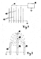
- FIG. 1 shows the geometric arrangement and the circuit diagram of a particular embodiment of the first mentioned invention
- Fig. 2 is an enlarged detail of the arrangement shown in Fig. 1 with an indicated course of the field lines .
- Fig. 3 schematically shows a preferred embodiment of the invention mentioned in the second place.
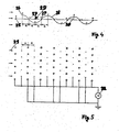
- 4 and 5 show a schematic proposal for a device according to the invention, wherein on the one hand the concentration of positive and negative ions at the time of the greatest field strength in a series connection of fan stages consisting of wires and on the other hand the arrangement of these wires and their electrical supply are shown.
- Fig. 1 the discharge wires 11 shown in section are brought to a potential of about 12 kV by the high voltage source 12.
- FIG. 2 shows an enlarged detail of the exemplary embodiment described in FIG. 1 with an indicated field line course, from which the mode of operation of the invention can be seen.
- the field lines run from the discharge wire 11 to the grounded: separator plates 13.
- the isolated separator plate 14 will attract 15 field lines with its edge closest to the discharge wire 11 as long as its potential is below the potential prevailing at point 15 without a separator plate 14.
- Along. of these field lines will also hit the plate 14 from ions coming from the discharge wire 11 and charge until their edge 15 begins to repel the field lines coming from the discharge wire.
- This plate 14 will now hold its potential until some minority ions of the other polarity have discharged it to such an extent that it is again forced to pass over the points 15 closest to the discharge wire charge.
- the separating plate 14 endeavors to keep its potential exactly at the value which prevails at the point 15 when the plate 14 is removed. This makes it possible to set the separation voltage completely freely in a very large interval, for example between 2 kV and 10 kV, by selecting the distance between the plate 14 and the wire 11.
- the simplification of the electrostatic air filter according to the invention also works satisfactorily if it is a wet electrostatic precipitator in which the ions are released into the air via an electrically charged liquid aerosol.
- the measures proposed in this invention basically also work when a potential reflection is carried out, that is to say that the discharge electrode is at earth potential and the corresponding electric field is applied in that the counterelectrodes integrated in the separating plates are now at high voltage potential.
- the high field strength causing the discharge also arises in this case around the discharge electrodes, which have a special shape for this purpose, such as wire, tip, etc.
- the ions now have opposite polarity and the insulated plates not only not allowed to charge, but that they have to be charged with the now very rare homopolar ions so that their potential comes close to the high-voltage separating plates.
- This mechanism works in principle, but it can be supported by a discharge path between the two different types of separator plates.
- wires 22 are embedded in corresponding recesses in the earthed separating plates in such a way that they also have earth potential. The easiest way to do this is through points 23 with a spot welding machine. These wires 22 are therefore parallel to the high-voltage separating plates 24. Since it makes no difference to the electrical field on the wire 22 whether a wire at negative high voltage is opposite an earthed plate or an earthed wire is opposite a plate under positive high voltage, negative ions are generated on this grounded wire 22, which then preferably leave the separating plates with the air when the positive plates 24 are seen at the height of the wire 22 in the flow direction or, as shown in the drawing figure 3, immediately after the height of the wire 22 ends.
- the ionization part is not shown in Fig. 3. It usually consists of thin, high-tension wires.
- the amount of negative ions formed can be determined for a given plate voltage either by the wire diameter or by the width of the recess or by both. However, the position of the end edge of the positive plate also determines the quantity of ions formed in addition to the amount of ions emerging.
- a further variant according to the invention consists of laterally offset, successively arranged thick wires 25 and thin wires 26, which, viewed in the direction of flow, are arranged at equal intervals a. Electrically, a thick and a thin wire are in pairs at the same potential, these pairs being functionally connected to the two outputs of an alternating current source of high voltage, so that the counter electrode 27 of the preceding stage is identical to the auxiliary electrode of the 'following stage, which only has to ensure that the ions only move in one direction.
- the thin wires 26 are the discharge electrodes, on which positive and negative ions alternate.
- the wavy line 28 shows somewhat schematically the concentration of the positive (above the axis 29) and the negative ions (below the axis 29) after prolonged operation, whereby neither the ions hitting the counterelectrode nor the newly formed ones were taken into account in the continuous wave train, as this is only hinted at in the dashed line 30.
- blower stages are arranged side by side and one behind the other to form a network of wires of different thicknesses to form a large blower, as is shown in the normal section of the wires.
- the distances of all wires are the same in the projection onto the flow direction 31 and are a cm.
- v is to be understood as the drift velocity. This is then also not the same for all ions, since these accumulate on different gases and hydrate to different extents and / or accumulate on dust particles, so that v is understood to mean an average drift speed.
Abstract
Description
Elektrostatischer Luftfilter bzw. elektrostatisches WechselstromgebläseElectrostatic air filter or electrostatic AC fan
Die Erfindung betrifft einen elektrostatischen Luftfilter mit einem Ionisationsteil und einem Abscheideteil, der sich aus abwechselnd unter Hochspannung stehenden und geerdeten Abscheideplatten zusammensetzt. Ferner betrifft die Erfindung ein elektrostatisches Wechselstromgebläse.The invention relates to an electrostatic air filter with an ionization part and a separating part which is composed of separating plates which are alternately under high voltage and earthed. The invention further relates to an electrostatic AC fan.
Die zuerst genannte Erfindung hat die Aufgabe, die Geräte durch Vereinfachung billiger zu machen. Elektrische Luftfiltergeräte, wie sie im Haushalt überwiegend verwendet werden, besitzen einen Ionisierungsteil und einen Abscheideteil. Der Ionisierungsteil besteht meistens aus Entladungselektroden, vorzugsweise dünnen Drähten auf entsprechendem Hochspannungspotential, und Gegenelektroden, die sich im allgemeinen auf Erdpotential befinden und so mit den Entladungselektroden ein elektrisches Feld definieren, das zur Bildung von Ionen um die Entladungselektroden führt.The first-mentioned invention has the task of making the devices cheaper by simplification. Electrical air filter devices, such as those used predominantly in the household, have an ionization part and a separating part. The ionization part usually consists of discharge electrodes, preferably thin wires at a corresponding high voltage potential, and counter electrodes, which are generally at ground potential and thus define an electric field with the discharge electrodes, which leads to the formation of ions around the discharge electrodes.
Je nach Polarität der Entladungselektrode wird eine der beiden Ionenarten von der Entladungselektrode abgestoßen und lagert sich an die in der Luft befindlichen Aerosole an, während die Luft zu dem Abscheideteil des Gerätes strömt.Depending on the polarity of the discharge electrode, one of the two types of ions is repelled by the discharge electrode and attaches itself to the aerosols in the air while the air flows to the separating part of the device.
Der Abscheideteil des Gerätes besteht im allgemeinen aus elektrisch leitenden, parallel zueinander angeordneten Platten, die abwechselnd auf Erdpotential und auf Hochspannungspotential liegen, sodaß sich zwischen ihnen ein elektrisches Feld ausbildet, in dem die geladenen Staubteilchen an die entsprechende Platte wandern und dort abgeschieden werden.The separating part of the device generally consists of electrically conductive plates which are arranged parallel to one another and which are alternately at ground potential and at high voltage potential, so that an electrical field is formed between them in which the charged dust Particles migrate to the corresponding plate and are deposited there.
Der entscheidende Nachteil der eben beschriebenen Apparatur liegt in den unterschiedlichen Spannungen, die Ionisierungsteil und Abscheideteil brauchen. Eine drahtförmige Entladungselektrode braucht im allgemeinen Spannungen zwischen 12 und 15 kV, während der Abscheideteil Plattenspannungen: zwischen 3 und 6 kV braucht. Zu der Abscheidespannung von 6 kV greift man nur in Kombinationen,mit der 12 kV Ionisierungsspannung, da dann die Herstellung zweier verschiedener Hochspannungen einfach über einen Transformator mit 6 kV Scheitelspannung und zwei Gleichrichtern, die für die Entladungselektrode in Spannungsverdoppelungsschaltung arbeiten. Die damit eingekauften Nachteile sind leider sehr groß. Abscheideplatten, die eine Spannung von 6 kV vertragen, müssen nicht nur besonders gut isoliert sein, sondern auch einen großen Abstand voneinander haben. Dies führt zu einer teuren Bauweise und einem großen Raumbedarf, da für die Abscheidung einer bestimmten Staubmenge eine entsprechende Plattenoberfläche zur Verfügung stehen muß.The decisive disadvantage of the apparatus just described lies in the different voltages that the ionizing part and the separating part need. A wire-shaped discharge electrode generally requires voltages between 12 and 15 kV, while the deposition part plate voltages: between 3 and 6 kV. The separation voltage of 6 kV is only used in combinations with the 12 kV ionization voltage, since then the production of two different high voltages is simply done via a transformer with a 6 kV peak voltage and two rectifiers, which work for the discharge electrode in a voltage doubling circuit. The disadvantages bought with it are unfortunately very large. Separation plates that can withstand a voltage of 6 kV not only have to be particularly well insulated, they also have to be far apart. This leads to an expensive construction and a large space requirement, since an appropriate plate surface must be available for the separation of a certain amount of dust.
Aus verschiedenen technologischen Gründen ist bei einem Luftfiltergerät die Erzeugung von positiven Ionen vorteilhafter und ebenso ist es kostengünstiger, die gleiche Hochspannung, oder zumindest einen Teil von ihr zur Aufladung der einen Plattensorte zu verwenden.For various technological reasons, the generation of positive ions is more advantageous in an air filter device and it is also less expensive to use the same high voltage, or at least part of it, to charge the one type of plate.
Ein Nachteil der bekannten Luftfiltergeräte liegt in der Tatsache, daß das positiv aufgeladene Aerosol niemals vollkommen eingesammelt werden kann und die Luft systematisch positiv aufgeladen wird. Dieser Vorgang wird noch dadurch verstärkt, daß die wenigen in der Luft vorhandenen negativen Ionen größtenteils ebenfalls an den Platten abgeschieden werden.A disadvantage of the known air filter devices lies in the fact that the positively charged aerosol can never be completely collected and the air is systematically positively charged. This process is intensified by the fact that the few negative ions present in the air are also largely deposited on the plates.
Bekannterweise wirkt sich eine starke positive Luftladung bei gleichzeitigem Fehlen negativer Ionen biologisch auf Tier und Mensch äußerst ungünstig aus. Es treten vorAs is known, a strong positive air charge with an absence of negative ions has a biologically extremely adverse effect on animals and humans. They come forward
allem Gereiztheit, Kopfschmerzen, Konzentrationsschwäche und Abgeschlagenheit, aber auch erhöhte Ansteckungsbereitschaft bei Erkältungs- und Infektionskrankheiten auf, Zustände, wie sie auch symptomatisch für Föhn- und Inversionswetterlagen sind.irritation, headache, lack of concentration and fatigue, but also increased willingness to catch colds and infectious diseases, conditions that are also symptomatic of hair dryer and inversion weather conditions.
Es ist daher ebenfalls Aufgabe der Erfindung, solche Filtergeräte so auszubilden, daß die Luft mit negativen Ionen angereichert wird.It is therefore also an object of the invention to design such filter devices so that the air is enriched with negative ions.
Schließlich stellt sich die Erfindung auch die Aufgabe, die bekannten elektrostatischen Wechselstromgebläse so auszubilden, daß sie mit unter hoher Spannung stehendem Wechselstrom betrieben werden können und/oder Ionen beiderlei Vorzeichens gleichzeitig zur Erzeugung der Gebläsewirkung verwenden.Finally, the invention also has the task of designing the known electrostatic alternating current blowers in such a way that they can be operated with high-voltage alternating current and / or simultaneously use ions of both signs to produce the blower effect.
Die Gebläsewirkung der bei den bekannten, Ionenwinde erzeugenden Vorrichtungen bewegten Ionen kommt durch die innere Reibung der Ionen im Gas zustande, wobei durch die Ionen genügend Luftmoleküle mitgenommen werden, um eine entsprechende Luftströmung zu erzielen. Analysiert man diesen Vorgang näher, so zeigt sich, daß die Reibung der Ionen im. Gas erst durch die Anlagerung an Gasmoleküle und in weiterer Folge an in der Luft gelösten Wassermolekülen groß genug wird, um diese Wirkung zu erzielen. Die Erfindung stellt sich daher auch in diesem Fall die Aufgabe, den Wirkungsgrad solcher Vorrichtungen zu erhöhen.The blower effect of the ions moving in the known devices producing ion winds comes about through the internal friction of the ions in the gas, with the ions carrying enough air molecules to achieve a corresponding air flow. If one analyzes this process in more detail, it becomes clear that the friction of the ions in the. Gas only becomes large enough when it is attached to gas molecules and subsequently to water molecules dissolved in the air to achieve this effect. In this case, too, the invention therefore has the task of increasing the efficiency of such devices.
Zur Lösung der an erster Stelle angeführten Aufgabe wird erfindungsgemäß vorgeschlagen, daß die unter Hochspannung stehende Gattung der Abscheideplatten vollkommen isoliert befestigt ist und mit keinem definierten Potential leitend verbunden ist, außer vorzugsweise mit weiteren Platten der gleichen Gattung, und daß die Hochspannung dieser Platten nur durch ihre Lage und ihren Abstand zu den Entladungselektroden des lonisationsteiles bestimmt ist. Die erwähnten Abscheideplatten beziehen ihre Hochspannung nicht aus einer elektronischen Schaltung, sondern aus dem Feld zwischen Entladungselektrode und Gegenelektrode, indem die Enden dieser Abscheideplatten so weit in das Feld hineinreichen, daß sie aus dem Felde bzw. mit Hilfe der sich in ihm bewegenden Ionen die Ladung beziehen, die sie zur Aufrechterhaltung der entsprechenden Abscheidespannung benötigen.To solve the problem mentioned in the first place, it is proposed according to the invention that the high-voltage genus of the separating plates is fastened in a completely insulated manner and is not conductively connected to any defined potential, except preferably with other plates of the same genus, and that the high voltage of these plates is only by their position and their distance from the discharge electrodes of the ionization part is determined. The separating plates mentioned do not obtain their high voltage from an electronic circuit, but rather from the field between the discharge electrode and the counterelectrode, in that the ends of these separating plates extend so far into the field that they draw the charge from the field or with the help of the ions moving in it, which they need to maintain the corresponding separating voltage.
Die zweite oben erwähnte Aufgabe wird erfindungsgemäß dadurch gelöst, daß zwischen den auf positiver Hochspannung stehenden Abscheideplatten und parallel zu ihnen Drähte gespannt sind, die in der Nähe oder auf Erdpotential liegen und bevorzugt am Ende der Abscheideplatten in Strömungsrichtung gesehen angeordnet sind.The second above-mentioned object is achieved according to the invention in that wires are tensioned between the separating plates which are at a positive high voltage and parallel to them, which are in the vicinity or at ground potential and are preferably arranged at the end of the separating plates as seen in the direction of flow.
Die Erfindung schlägt zur Lösung der an dritter Stelle angegebenen Aufgabe vor, daß die zur Erzeugung einer gerichteten Strömung notwendige Gegenelektrode, Entladungselektrode und vorzugsweise Hilfselektrode, die an sich bekannt sind, mit unter hoher Spannung stehendem Wechselstrom betrieben werden können, da diese Elektroden in Strömungsrichtung gesehen in Abständen angeordnet sind, die zueinander und zu den Strömungsgeschwindigkeiten der Gase bzw. den Driftgeschwindigkeiten der Ionen in den Gasen bei vorgegebenen Wechselstromfrequenzen in ganz bestimmten Verhältnissen stehen, insbesondere daß der Abstand zwischen Entladungs- und Gegenelektrode bei vorgegebener Frequenz zu der Strömungsgeschwindigkeit des Gases bzw. der Driftgeschwindigkeit der Ionen in dem Gas in einem ganz bestimmten Verhältnis steht, insbesondere, daß die kleinste dieser Geschwindigkeiten größer oder vergleichbar dem Produkt aus Frequenz und Abstand der Entladungszur Gegenelektrode ist.To achieve the object stated in the third place, the invention proposes that the counter electrode, discharge electrode and preferably auxiliary electrode, which are necessary for generating a directed flow, and which are known per se, can be operated with high-voltage alternating current, since these electrodes are seen in the direction of flow are arranged at intervals which are in relation to one another and to the flow velocities of the gases or the drift velocities of the ions in the gases at predetermined alternating current frequencies in very specific ratios, in particular that the distance between the discharge and counter electrodes at a predetermined frequency is relative to the flow velocity of the gas or the drift velocity of the ions in the gas is in a very specific ratio, in particular that the smallest of these velocities is greater or comparable to the product of the frequency and the distance of the discharge from the counterelectrode.
Eine vorzugsweise-Ausführungsform der Vorrichtung hat eine Anzahl von Gebläsestufen hintereinander angeordnet, wobei es durch die Abstimmung der Elektrodenabstände und der Strömungsgeschwindigkeit der Gase bzw. der Driftgeschwindigkeit der Ionen zu-einem Resonanzeffekt kommt, der höhere Gebläseleistungen bzw. den Aufbau einer größeren Druckdifferenz gestattet.A preferred embodiment of the device has a number of blower stages arranged one behind the other, whereby the coordination of the electrode spacings and the flow velocity of the gases or the drift velocity of the ions leads to a resonance effect which permits higher blower outputs or the establishment of a larger pressure difference.
Schließlich wird die an vierter Stelle genannte Aufgabe durch die Erfindung dadurch gelöst, daß unipolar aufgeladenes Flüssigkeitsaerosol durch eine an sich bekannte unter Hochspannung stehende Düse oder einer oder mehrerer Düsen mit nachgeschalteter Entladungsstrecke erzeugt wird und durch die Geometrie von unter Hochspannung stehender Düse bzw. Aufladungselektrode und einer geeigneten Gegenelektrode auf Erdpotential gezwungen wird, vorzugsweise in eine Richtung oder zumindest in Richtung eines Kegels mit dem Öffnungswinkel kleiner als 90° zu wandern, insbesondere dann, wenn die durch eine Düse vorgegebene Richtung und Energie der Flüssigkeitstropfen aufgezehrt ist, wobei das Elektroaerosol eine Strecke von mindestens 20 bis 30 mm und eine Potentialdifferenz von 10 bis 30 kV, vorzugsweise 15 bis 25 kV zur Verfügung hat, um auf dem Weg zur stromabwärts'liegenden Gegenelektrode entsprechend große Luftmengen mitnehmen zu können.Finally, the fourth-mentioned object is achieved by the invention in that unipolar charged liquid aerosol is generated by a known high-voltage nozzle or one or more nozzles with a downstream discharge path and by the geometry of the high-voltage nozzle or charging electrode and a suitable counterelectrode is forced to earth potential, preferably to move in one direction or at least in the direction of a cone with an opening angle of less than 90 °, in particular when the direction and energy of the liquid drops, which is predetermined by a nozzle, is consumed, the electro-aerosol being a stretch of at least 20 to 30 mm and a potential difference of 10 to 30 kV, preferably 15 to 25 kV, in order to be able to take along correspondingly large amounts of air on the way to the downstream counter electrode.
Ist die zu zerstäubende Flüssigkeit elektrisch leitend oder will man aus einem anderen Grund vermeiden, die Düse auf Hochspannungspotential zu legen, so kann erfindungsgemäß auch Düse bzw. Aufladungselektrode auf Erdpotential, die Gegenelektrode dagegen auf Hochspannungspotential liegen.If the liquid to be atomized is electrically conductive or if for another reason you want to avoid placing the nozzle at high voltage potential, then according to the invention the nozzle or charging electrode can also be at earth potential, while the counter electrode can be at high voltage potential.
Die Leistungsaufnahme eines solchen Aerosolgebläses besteht im wesentlichen in der Erzeugung der Hochspannung bei einem bestimmten Strom, der die Anzahl der wandernden Ionen vorgibt. Geht man nun durch die Bildung des Elektroaerosols sicher, daß jedes Ion schon bei seiner Bildung auf einem Flüssigkeitstropfen sitzt, so ist für die Wanderung der Ladung zur Gegenelektrode eine maximale innere Luftreibung und damit ein optimaler Wirkungsgrad sichergestellt.The power consumption of such an aerosol blower essentially consists in the generation of the high voltage at a specific current, which specifies the number of migrating ions. If the formation of the electro-aerosol ensures that each ion sits on a drop of liquid as it is being formed, maximum internal air friction and thus optimum efficiency are ensured for the charge to migrate to the counter electrode.
Die einzelnen Erfindungsgegenstände sind in der Zeichnung an Hand-von Ausführungsbeispielen näher veranschaulicht. Es zeigen: Fig. 1 die geometrische Anordnung und das Schaltschema einer besonderen Ausführungsform der zuerst erwähnten Erfindung und Fig. 2 eine Ausschnittsvergrösserung der in Fig. 1 gezeigten Anordnung mit angedeutetem Verlauf der Feldlinien..Fig. 3 zeigt ein bevorzugtes Ausführungsbeispiel der an zweiter Stelle genannten Erfindung schematisch. Die Fig. 4 und 5 zeigen einen schematischen Vorschlag für eine erfindungsgemäße Vorrichtung, wobei einerseits schematisch die Konzentration positiver und negativer Ionen zum Zeitpunkt der größten Feldstärke in einer Serienschaltung von aus Drähten bestehenden Gebläsestufen und anderseits die Anordnung dieser Drähte und ihre elektrische Anspeisung dargestellt sind.The individual subjects of the invention are illustrated in more detail in the drawing using exemplary embodiments. 1 shows the geometric arrangement and the circuit diagram of a particular embodiment of the first mentioned invention and Fig. 2 is an enlarged detail of the arrangement shown in Fig. 1 with an indicated course of the field lines .. Fig. 3 schematically shows a preferred embodiment of the invention mentioned in the second place. 4 and 5 show a schematic proposal for a device according to the invention, wherein on the one hand the concentration of positive and negative ions at the time of the greatest field strength in a series connection of fan stages consisting of wires and on the other hand the arrangement of these wires and their electrical supply are shown.
In Fig. 1 werden die im Schnitt gezeigten Entladungsdrähte 11 durch die Hochspannungsquelle 12 etwa auf ein Potential von 12 kVgebracht. Im Luftstrom abwärts sind geerdete Platten 13 und isoliert angebrachte, mit keinem definierten Potential elektrisch verbundene, auf Hochspannung von etwa 3 kV stehende Abscheideplatten 14 abwechselnd angeordnet.In Fig. 1, the
In Fig. 2 sieht man eine Ausschnittsvergrößerung des in Fig. 1 beschriebenen Ausführungsbeispiels mit einem angedeuteten Feldlinienverlauf, aus dem die Wirkungsweise der Erfindung ersehen werden kann. Die Feldlinien verlaufen von dem Entladungsdraht 11 zu den geerdeten : Abscheideplatten 13. Die isoliert angeordnete Abscheideplatte 14 wird solange mit ihrer dem Entladungsdraht 11 nächstliegenden Kante 15 Feldlinien anziehen, solange ihr Potential unter dem an der Stelle 15 herrschenden Potential ohne Abscheideplatte 14 ist. Entlang. dieser Feldlinien werden auch vön dem Entladungsdraht 11 ausgehende Ionen die Platte 14 treffen und solange aufladen, bis ihre Kante 15 beginnt, die von dem Entladungsdraht ausgehenden Feldlinien abzustoßen. Diese Platte 14 wird nun so lange ihr Potential halten, bis einige in Minderheit' vorliegende Ionen der anderen Polarität sie so weit entladen haben, daß sie wieder gezwungen ist, sich über die dem Entladungsdraht nächstliegenden Punkte 15 wieder aufzuladen. Durch diesen Regelmechanismus ist die Abscheideplatte 14 bestrebt, ihr Potential genau auf dem Wert zu halten, der an der Stelle 15 herrscht, wenn die Platte 14 entfernt ist. Damit ist die Möglichkeit gegeben, durch die Wahl des Abstandes der Platte 14 zum Draht 11 die Abscheidespannung in einem sehr großen Intervall, etwa zwischen 2 kV und 10 kV vollkommen frei einzustellen.FIG. 2 shows an enlarged detail of the exemplary embodiment described in FIG. 1 with an indicated field line course, from which the mode of operation of the invention can be seen. The field lines run from the
Die erfindungsgemäße Vereinfachung des elektrostatischen Luftfilters arbeitet ebenfalls zufriedenstellend, wenn es sich dabei um einen Naß-Elektrofilter handelt, bei dem die Ionen über ein elektrisch aufgeladenes Flüssigkeitsaerosol in die Luft abgegeben werden.The simplification of the electrostatic air filter according to the invention also works satisfactorily if it is a wet electrostatic precipitator in which the ions are released into the air via an electrically charged liquid aerosol.
Arbeitsspannungen für die isoliert angeordneten Abscheideplatten in der Nähe und unter 2 kV sind leichter zu erreichen, wenn als zusätzliche Stabilisierung zwischen diesen Platten und der Erdung eine Funkenstrecke eingerichtet wird.Working voltages for the isolated separator plates in the vicinity and below 2 kV are easier to achieve if a spark gap is set up as additional stabilization between these plates and the ground.
Die in dieser Erfindung vorgeschlagenen Maßnahmenarbeiten grundsätzlich auch dann, wenn eine Potentialspiegelung durchgeführt wird, d.h., daß die Entladungselektrode sich auf Erdpotential befindet und das entsprechende elektrische Feld dadurch aufgebracht wird, daß sich nun die in die Abscheideplatten integrierten Gegenelektroden auf Hochspannungspotential befinden. Die die Entladung hervorrufende hohe Feldstärke entsteht auch in diesem Fall um die Entladungselektroden, die zu diesem Zweck eine besondere Formgebung aufweisen, wie etwa Draht, Spitze etc. Dabei ist nur zu berücksichtigen, daß die Ionen jetzt eine gegenpolige Polarität besitzen und die isoliert angebrachten Platten nicht nur nicht aufladen dürfen, sondern daß sich diese mit Hilfe der jetzt sehr seltenen gleichpoligen Ionen so aufladen müssen, daß ihr Potential in die Nähe der unter Hochspannung stehenden Abscheideplatten gelangt. Dieser Mechanismus funktioniert im Prinzip, man kann ihn jedoch durch eine Entladungsstrecke zwischen den beiden verschiedenartigen Gattungen von Abscheideplatten unterstützen.The measures proposed in this invention basically also work when a potential reflection is carried out, that is to say that the discharge electrode is at earth potential and the corresponding electric field is applied in that the counterelectrodes integrated in the separating plates are now at high voltage potential. The high field strength causing the discharge also arises in this case around the discharge electrodes, which have a special shape for this purpose, such as wire, tip, etc. It only has to be taken into account that the ions now have opposite polarity and the insulated plates not only not allowed to charge, but that they have to be charged with the now very rare homopolar ions so that their potential comes close to the high-voltage separating plates. This mechanism works in principle, but it can be supported by a discharge path between the two different types of separator plates.
Gemäß Fig. 3 sind in entsprechenden Aussparungen der geerdeten Abscheideplatten 21 Drähte 22 so eingelassen, daß sie ebenfalls Erdpotential aufweisen. Dies geschieht am einfachsten durch Anpunkten 23 mit einer Punktschweißmaschine. Diese Drähte 22 liegen somit parallel zu den unter Hochspannung stehenden Abscheideplatten 24. Da es für das elektrische Feld am Draht 22 keinen Unterschied macht, ob ein Draht auf negativer Hochspannung einer geerdeten Platte gegenüberliegt oder ein geerdeter Draht einer unter positiver Hochspannung stehenden-Platte gegenüberliegt, so werden an diesem geerdeten Draht 22 negative Ionen erzeugt, die dann bevorzugt mit der Luft die Abscheideplatten verlassen, wenn die positiven Platten 24 in Strömungsrichtung gesehen auf der Höhe des Drahtes 22 oder wie in der Zeichnungsfigur 3 dargestellt ist, unmittelbar nach der Höhe des Drahtes 22 enden. Der Ionisationsteil ist in Fig. 3 nicht dargestellt. Er besteht üblicherweise aus dünnen, unter Hochspannung stehenden Drähten.According to FIG. 3,
Die Menge der gebildeten negativen Ionen kann bei vorgegebener Plattenspannung entweder durch den Drahtdurchmesser oder durch die Breite der Aussparung oder durch beides bestimmt werden. Aber auch die Lage der Endkante der positiven Platte bestimmt neben der Menge der austretenden Ionen die.Menge der gebildeten Ionen.The amount of negative ions formed can be determined for a given plate voltage either by the wire diameter or by the width of the recess or by both. However, the position of the end edge of the positive plate also determines the quantity of ions formed in addition to the amount of ions emerging.
Gemäß Fig. 4 besteht eine weitere erfindungsgemäße Variante aus seitlich versetzten, aufeinanderfolgend angeordneten dicken Drähten 25 und dünnen Drähten 26, die, in Strömungsrichtung gesehen, in gleichen Abständen a angeordnet sind. Elektrisch befindet sich paarweise jeweils ein dicker und ein dünner Draht auf dem gleichen Potential, wobei funktionsgemäß diese Paare abwechselnd an den beiden Ausgängen einer Wechselstromquelle hoher Spannung liegen, sodaß.die Gegenelektrode 27 der vorangehenden Stufe identisch ist mit der Hilfselektrode der' folgenden Stufe, die nur sicherzustellen hat, daß sich die Ionen nur in eine Richtung bewegen. Die dünnen Drähte 26 sind die Entladungselektroden, an denen sich abwechselnd positive und negative Ionen bilden. Die Wellenlinie 28 gibt etwas schematisch die Konzentration der positiven (über der Achse 29) und der negativen Ionen (unter der Achse 29) nach längerem Betrieb an, wobei im fortlaufenden Wellenzug weder die auf die Gegenelektrode treffenden Ionen noch die neu gebildeten berücksichtigt wurden, wie dies nur andeutungsweise in der strichlierten Linie 30 der Fall ist.4, a further variant according to the invention consists of laterally offset, successively arranged
Gemäß Fig. 5 werden solche Gebläsestufen durch Anordnung neben- und hintereinander zu einem Netz von verschieden dicken Drähten zu einem großen Gebläse zusammengestellt, wie dies im Schnitt normal zu den Drähten dargestellt ist. Die Abstände aller Drähte sind in der Projektion auf die Strömungsrichtung 31 gleich groß und betragen a cm.According to FIG. 5, such blower stages are arranged side by side and one behind the other to form a network of wires of different thicknesses to form a large blower, as is shown in the normal section of the wires. The distances of all wires are the same in the projection onto the flow direction 31 and are a cm.
Soll nun der in Fig. 4 gezeigte Wellenzug stimmen und hat die Wechselstromquelle 32 die Frequenz f Hertz, so gilt für die Strömungsgeschwindigkeit des Gases v v = 4af.If the wave train shown in FIG. 4 is to be correct and the alternating current source 32 has the frequency f Hertz, then the flow velocity of the gas is vv = 4a f .
Weicht die Driftgeschwindigkeit der Ionen im Gas von der Strömungsgeschwindigkeit des Gases, gemessen im gleichen Koordinatensystem, stark ab, so ist unter v natürlich die Driftgeschwindigkeit zu verstehen. Diese ist dann auch nicht für alle Ionen gleich, da diese sich an verschiedene Gase anlagern und verschieden stark hydratisieren und/oder an Staubteilchen anlagern,sodaßdann unter v eine mittlere Driftgeschwindigkeit verstanden werden soll.If the drift velocity of the ions in the gas deviates greatly from the flow velocity of the gas, measured in the same coordinate system, then of course v is to be understood as the drift velocity. This is then also not the same for all ions, since these accumulate on different gases and hydrate to different extents and / or accumulate on dust particles, so that v is understood to mean an average drift speed.
Claims (14)
Applications Claiming Priority (8)
| Application Number | Priority Date | Filing Date | Title |
|---|---|---|---|
| AT239780A AT372301B (en) | 1980-05-06 | 1980-05-06 | ELECTROSTATIC AIR FILTER |
| AT2398/80 | 1980-05-06 | ||
| AT2397/80 | 1980-05-06 | ||
| AT239880 | 1980-05-06 | ||
| AT3806/80 | 1980-07-23 | ||
| AT380680 | 1980-07-23 | ||
| AT3808/80 | 1980-07-23 | ||
| AT380880 | 1980-07-23 |
Publications (3)
| Publication Number | Publication Date |
|---|---|
| EP0039669A2 true EP0039669A2 (en) | 1981-11-11 |
| EP0039669A3 EP0039669A3 (en) | 1983-09-14 |
| EP0039669B1 EP0039669B1 (en) | 1985-12-27 |
Family
ID=27421762
Family Applications (1)
| Application Number | Title | Priority Date | Filing Date |
|---|---|---|---|
| EP19810890074 Expired EP0039669B1 (en) | 1980-05-06 | 1981-05-05 | Electrostatic air filter |
Country Status (2)
| Country | Link |
|---|---|
| EP (1) | EP0039669B1 (en) |
| DE (1) | DE3173286D1 (en) |
Cited By (10)
| Publication number | Priority date | Publication date | Assignee | Title |
|---|---|---|---|---|
| EP0114178A1 (en) * | 1982-12-30 | 1984-08-01 | Nichiele Corporation | Air cleaning apparatus |
| DE3409999A1 (en) * | 1983-03-18 | 1984-09-20 | Ricoh Co., Ltd., Tokio/Tokyo | Device for producing an ion wind |
| EP0125379A2 (en) * | 1983-05-13 | 1984-11-21 | Endo, Keiko | Air flow generating apparatus |
| US4689056A (en) * | 1983-11-23 | 1987-08-25 | Nippon Soken, Inc. | Air cleaner using ionic wind |
| DE19842068A1 (en) * | 1998-09-15 | 2000-03-16 | Brand Gerhart Rosemarie | Air transport system for transporting air in electrostatic fields ionizes the air and moves it between two electrodes using D.C. voltage towards gas-transmissive electrode at positive voltage |
| EP1033171A2 (en) * | 1999-03-01 | 2000-09-06 | Heinz Aigner | Electrostatic filter, especially for cleaning exhaust air in vehicular tunnels, subterranean garages and the like |
| EP1948363A1 (en) * | 2005-11-01 | 2008-07-30 | Roger Gale | Single stage electrostatic precipitator |
| WO2009059451A1 (en) * | 2007-11-05 | 2009-05-14 | Su, Jiting | An electrostatic precipitator |
| CN106694228A (en) * | 2016-11-18 | 2017-05-24 | 江苏智石科技有限公司 | Air filtering device |
| CN109239052A (en) * | 2018-10-29 | 2019-01-18 | 中国科学院上海技术物理研究所 | Spacefarer's urine detection method based on liquid core waveguide Raman spectrum |
Citations (10)
| Publication number | Priority date | Publication date | Assignee | Title |
|---|---|---|---|---|
| DE1127332B (en) * | 1955-08-30 | 1962-04-12 | Westinghouse Electric Corp | Electrostatic precipitator |
| GB913172A (en) * | 1959-02-20 | 1962-12-19 | Guenter Hermann Wilhelm Jucho | Improvements in or relating to electrostatic filters |
| FR1593800A (en) * | 1968-12-29 | 1970-06-01 | ||
| DE2028153A1 (en) * | 1970-04-02 | 1971-10-14 | Inst Za Aerodinamicka I Termod | Electronic air filter |
| FR2090046A1 (en) * | 1970-05-15 | 1972-01-14 | Gourdine Systems Inc | |
| US3638058A (en) * | 1970-06-08 | 1972-01-25 | Robert S Fritzius | Ion wind generator |
| DE2052014A1 (en) * | 1970-10-23 | 1972-04-27 | Messerschmitt Boelkow Blohm | Ion thruster |
| FR2282670A1 (en) * | 1974-08-21 | 1976-03-19 | Equip Climatique | Regulator for ionic air conditioner - has insulating sensor tube with electrodes and control circuits for generators |
| DE2448979A1 (en) * | 1974-10-15 | 1976-04-29 | Licentia Gmbh | Electrostatic air filter with high tension ionising electrode - has high efficiency parallel collecting plates charged at comparatively low voltage |
| GB2016305A (en) * | 1978-03-02 | 1979-09-26 | Pontius D H | Electrostatically removing particulate material from gas |
Family Cites Families (1)
| Publication number | Priority date | Publication date | Assignee | Title |
|---|---|---|---|---|
| DE1679532B1 (en) * | 1967-10-09 | 1970-12-10 | Berckheim Graf Von | Arrangement for generating unipolar air ions |
-
1981
- 1981-05-05 DE DE8181890074T patent/DE3173286D1/en not_active Expired
- 1981-05-05 EP EP19810890074 patent/EP0039669B1/en not_active Expired
Patent Citations (10)
| Publication number | Priority date | Publication date | Assignee | Title |
|---|---|---|---|---|
| DE1127332B (en) * | 1955-08-30 | 1962-04-12 | Westinghouse Electric Corp | Electrostatic precipitator |
| GB913172A (en) * | 1959-02-20 | 1962-12-19 | Guenter Hermann Wilhelm Jucho | Improvements in or relating to electrostatic filters |
| FR1593800A (en) * | 1968-12-29 | 1970-06-01 | ||
| DE2028153A1 (en) * | 1970-04-02 | 1971-10-14 | Inst Za Aerodinamicka I Termod | Electronic air filter |
| FR2090046A1 (en) * | 1970-05-15 | 1972-01-14 | Gourdine Systems Inc | |
| US3638058A (en) * | 1970-06-08 | 1972-01-25 | Robert S Fritzius | Ion wind generator |
| DE2052014A1 (en) * | 1970-10-23 | 1972-04-27 | Messerschmitt Boelkow Blohm | Ion thruster |
| FR2282670A1 (en) * | 1974-08-21 | 1976-03-19 | Equip Climatique | Regulator for ionic air conditioner - has insulating sensor tube with electrodes and control circuits for generators |
| DE2448979A1 (en) * | 1974-10-15 | 1976-04-29 | Licentia Gmbh | Electrostatic air filter with high tension ionising electrode - has high efficiency parallel collecting plates charged at comparatively low voltage |
| GB2016305A (en) * | 1978-03-02 | 1979-09-26 | Pontius D H | Electrostatically removing particulate material from gas |
Cited By (13)
| Publication number | Priority date | Publication date | Assignee | Title |
|---|---|---|---|---|
| EP0114178A1 (en) * | 1982-12-30 | 1984-08-01 | Nichiele Corporation | Air cleaning apparatus |
| DE3409999A1 (en) * | 1983-03-18 | 1984-09-20 | Ricoh Co., Ltd., Tokio/Tokyo | Device for producing an ion wind |
| EP0125379A2 (en) * | 1983-05-13 | 1984-11-21 | Endo, Keiko | Air flow generating apparatus |
| EP0125379A3 (en) * | 1983-05-13 | 1985-05-15 | Endo, Keiko | Air flow generating apparatus |
| US4689056A (en) * | 1983-11-23 | 1987-08-25 | Nippon Soken, Inc. | Air cleaner using ionic wind |
| DE19842068A1 (en) * | 1998-09-15 | 2000-03-16 | Brand Gerhart Rosemarie | Air transport system for transporting air in electrostatic fields ionizes the air and moves it between two electrodes using D.C. voltage towards gas-transmissive electrode at positive voltage |
| EP1033171A2 (en) * | 1999-03-01 | 2000-09-06 | Heinz Aigner | Electrostatic filter, especially for cleaning exhaust air in vehicular tunnels, subterranean garages and the like |
| EP1033171A3 (en) * | 1999-03-01 | 2001-03-28 | Heinz Aigner | Electrostatic filter, especially for cleaning exhaust air in vehicular tunnels, subterranean garages and the like |
| EP1948363A1 (en) * | 2005-11-01 | 2008-07-30 | Roger Gale | Single stage electrostatic precipitator |
| EP1948363A4 (en) * | 2005-11-01 | 2011-04-27 | Roger Gale | Single stage electrostatic precipitator |
| WO2009059451A1 (en) * | 2007-11-05 | 2009-05-14 | Su, Jiting | An electrostatic precipitator |
| CN106694228A (en) * | 2016-11-18 | 2017-05-24 | 江苏智石科技有限公司 | Air filtering device |
| CN109239052A (en) * | 2018-10-29 | 2019-01-18 | 中国科学院上海技术物理研究所 | Spacefarer's urine detection method based on liquid core waveguide Raman spectrum |
Also Published As
| Publication number | Publication date |
|---|---|
| EP0039669B1 (en) | 1985-12-27 |
| EP0039669A3 (en) | 1983-09-14 |
| DE3173286D1 (en) | 1986-02-06 |
Similar Documents
| Publication | Publication Date | Title |
|---|---|---|
| DE3529057C2 (en) | ||
| EP0185966B1 (en) | Process and device for cleaning a gas stream containing solid or liquid particles in suspension | |
| DE2363149C3 (en) | Electrostatic precipitator | |
| CH625974A5 (en) | ||
| DE899017C (en) | Device for electrostatic spray painting | |
| EP0039669A2 (en) | Electrostatic air filter | |
| DE3832879A1 (en) | Device for continuous electrostatic precipitation of particles suspended in a stream of gas | |
| DE2538958C3 (en) | Disinfection device | |
| DE2341541C2 (en) | Electrostatic precipitator | |
| DE1078096B (en) | Electrostatic precipitator for separating solid particles from gases | |
| DE2743292A1 (en) | PROCESS AND DEVICE FOR SEPARATING FINE DUST AND SALT AEROSOLS FROM CRUDE GAS TROEMS | |
| DE2254452A1 (en) | ELECTRIC FILTER | |
| WO1989004724A1 (en) | Electrostatic filter for continuous separation of solid or liquid particles suspended in a gas stream | |
| DE3609698A1 (en) | Device and method for ionisation or neutralisation of a gas flow and the particles contained in it | |
| DE2546025C3 (en) | Device for electrostatic spraying of continuously transported webs | |
| DE655635C (en) | Process for the electrical purification of gases | |
| DE1025390B (en) | Electrostatic precipitator | |
| DE671277C (en) | Process for the electrical separation of suspended matter in a highly insulating aerosol from its carrier gas | |
| DE3713156A1 (en) | Process for oil application onto metal strips | |
| DE633096C (en) | Process and device for the separation of dust and grainy parts from mineral mixtures and other substances | |
| CH566171A5 (en) | Disposable electrofilter has simple bent lug contacts - between positive plates bypassing negative plates through openings and vice versa | |
| DE752566C (en) | Electrostatic precipitator with successive spray charging and spray discharge-free separation of the suspended particles in the course of the gas flow | |
| DE3329637C2 (en) | Device for dedusting industrial gases | |
| DE2254684A1 (en) | Electrostatic dust precipitator - with replaceable elements in catcher electrodes | |
| DE10018010A1 (en) | Dust extraction device has corona charging electrode and counter electrode on either side of material, discharge electrode and suction device close to discharge electrode, preferably after it |
Legal Events
| Date | Code | Title | Description |
|---|---|---|---|
| PUAI | Public reference made under article 153(3) epc to a published international application that has entered the european phase |
Free format text: ORIGINAL CODE: 0009012 |
|
| AK | Designated contracting states |
Designated state(s): BE CH DE FR GB IT LI NL SE |
|
| 17P | Request for examination filed |
Effective date: 19820506 |
|
| PUAL | Search report despatched |
Free format text: ORIGINAL CODE: 0009013 |
|
| AK | Designated contracting states |
Designated state(s): BE CH DE FR GB IT LI NL SE |
|
| RAP1 | Party data changed (applicant data changed or rights of an application transferred) |
Owner name: FLECK, CARL MARIA, DR. |
|
| ITF | It: translation for a ep patent filed |
Owner name: MARCHI & MITTLER S.R.L. |
|
| GRAA | (expected) grant |
Free format text: ORIGINAL CODE: 0009210 |
|
| AK | Designated contracting states |
Designated state(s): BE CH DE FR GB IT LI NL SE |
|
| REF | Corresponds to: |
Ref document number: 3173286 Country of ref document: DE Date of ref document: 19860206 |
|
| EN | Fr: translation not filed | ||
| PLBE | No opposition filed within time limit |
Free format text: ORIGINAL CODE: 0009261 |
|
| STAA | Information on the status of an ep patent application or granted ep patent |
Free format text: STATUS: NO OPPOSITION FILED WITHIN TIME LIMIT |
|
| 26N | No opposition filed | ||
| ET | Fr: translation filed | ||
| REG | Reference to a national code |
Ref country code: FR Ref legal event code: BR |
|
| PGFP | Annual fee paid to national office [announced via postgrant information from national office to epo] |
Ref country code: FR Payment date: 19910429 Year of fee payment: 11 |
|
| ITTA | It: last paid annual fee | ||
| PGFP | Annual fee paid to national office [announced via postgrant information from national office to epo] |
Ref country code: DE Payment date: 19920418 Year of fee payment: 12 |
|
| PGFP | Annual fee paid to national office [announced via postgrant information from national office to epo] |
Ref country code: GB Payment date: 19920430 Year of fee payment: 12 |
|
| PGFP | Annual fee paid to national office [announced via postgrant information from national office to epo] |
Ref country code: CH Payment date: 19920512 Year of fee payment: 12 Ref country code: BE Payment date: 19920512 Year of fee payment: 12 |
|
| PGFP | Annual fee paid to national office [announced via postgrant information from national office to epo] |
Ref country code: SE Payment date: 19920527 Year of fee payment: 12 |
|
| PGFP | Annual fee paid to national office [announced via postgrant information from national office to epo] |
Ref country code: NL Payment date: 19920531 Year of fee payment: 12 |
|
| PG25 | Lapsed in a contracting state [announced via postgrant information from national office to epo] |
Ref country code: GB Effective date: 19930505 |
|
| PG25 | Lapsed in a contracting state [announced via postgrant information from national office to epo] |
Ref country code: SE Effective date: 19930506 |
|
| PG25 | Lapsed in a contracting state [announced via postgrant information from national office to epo] |
Ref country code: CH Effective date: 19930531 Ref country code: LI Effective date: 19930531 Ref country code: BE Effective date: 19930531 |
|
| BERE | Be: lapsed |
Owner name: FLECK CARL MARIA Effective date: 19930531 |
|
| PG25 | Lapsed in a contracting state [announced via postgrant information from national office to epo] |
Ref country code: NL Effective date: 19931201 |
|
| GBPC | Gb: european patent ceased through non-payment of renewal fee |
Effective date: 19930505 |
|
| NLV4 | Nl: lapsed or anulled due to non-payment of the annual fee | ||
| REG | Reference to a national code |
Ref country code: CH Ref legal event code: PL |
|
| PG25 | Lapsed in a contracting state [announced via postgrant information from national office to epo] |
Ref country code: DE Effective date: 19940201 |
|
| EUG | Se: european patent has lapsed |
Ref document number: 81890074.8 Effective date: 19931210 |
|
| PG25 | Lapsed in a contracting state [announced via postgrant information from national office to epo] |
Ref country code: FR Free format text: LAPSE BECAUSE OF FAILURE TO SUBMIT A TRANSLATION OF THE DESCRIPTION OR TO PAY THE FEE WITHIN THE PRESCRIBED TIME-LIMIT Effective date: 20000531 |
|
| PG25 | Lapsed in a contracting state [announced via postgrant information from national office to epo] |
Ref country code: FR Free format text: LAPSE BECAUSE OF FAILURE TO SUBMIT A TRANSLATION OF THE DESCRIPTION OR TO PAY THE FEE WITHIN THE PRESCRIBED TIME-LIMIT Effective date: 19920531 |