EP0044263A1 - Quick response flow-current converter, especially to control actuation or distribution devices - Google Patents
Quick response flow-current converter, especially to control actuation or distribution devices Download PDFInfo
- Publication number
- EP0044263A1 EP0044263A1 EP81440017A EP81440017A EP0044263A1 EP 0044263 A1 EP0044263 A1 EP 0044263A1 EP 81440017 A EP81440017 A EP 81440017A EP 81440017 A EP81440017 A EP 81440017A EP 0044263 A1 EP0044263 A1 EP 0044263A1
- Authority
- EP
- European Patent Office
- Prior art keywords
- solenoid valves
- electro
- comparator
- solenoid valve
- valves
- Prior art date
- Legal status (The legal status is an assumption and is not a legal conclusion. Google has not performed a legal analysis and makes no representation as to the accuracy of the status listed.)
- Granted
Links
Images

Classifications
-
- F—MECHANICAL ENGINEERING; LIGHTING; HEATING; WEAPONS; BLASTING
- F15—FLUID-PRESSURE ACTUATORS; HYDRAULICS OR PNEUMATICS IN GENERAL
- F15B—SYSTEMS ACTING BY MEANS OF FLUIDS IN GENERAL; FLUID-PRESSURE ACTUATORS, e.g. SERVOMOTORS; DETAILS OF FLUID-PRESSURE SYSTEMS, NOT OTHERWISE PROVIDED FOR
- F15B9/00—Servomotors with follow-up action, e.g. obtained by feed-back control, i.e. in which the position of the actuated member conforms with that of the controlling member
- F15B9/02—Servomotors with follow-up action, e.g. obtained by feed-back control, i.e. in which the position of the actuated member conforms with that of the controlling member with servomotors of the reciprocatable or oscillatable type
- F15B9/03—Servomotors with follow-up action, e.g. obtained by feed-back control, i.e. in which the position of the actuated member conforms with that of the controlling member with servomotors of the reciprocatable or oscillatable type with electrical control means
-
- G—PHYSICS
- G05—CONTROLLING; REGULATING
- G05D—SYSTEMS FOR CONTROLLING OR REGULATING NON-ELECTRIC VARIABLES
- G05D3/00—Control of position or direction
- G05D3/12—Control of position or direction using feedback
- G05D3/14—Control of position or direction using feedback using an analogue comparing device
- G05D3/18—Control of position or direction using feedback using an analogue comparing device delivering a series of pulses
Definitions
- the present invention relates to the field of servo-control of devices for operating loads, or the like, or of distribution devices, and has for its object a current-flow converter with fast response intended for this purpose.
- solenoid valves which are logic distributors.
- several solenoid valves having different flow rates, therefore different passage diameters are grouped into a distribution group allowing the obtaining of several flow rates varying with the solenoid valve (s) used.
- the number of possible operating speeds is a direct function of the number of solenoid valves used, so that for a relatively fine conversion of the flow rates, and therefore of the speeds, the distribution group becomes relatively large, each solenoid valve being generally followed by an adjustable choke.
- the present invention aims to overcome the drawbacks of known servo devices.
- a current-flow converter with rapid response in particular for the servo-control of devices for operating loads, or the like, or of distribution devices, characterized in that it is essentially constituted by one or several solenoid valves of the same type with rapid switching frequency, each controlled by an electronic control member, and connected by their inlet orifice to an energy reservoir, and by one of their outlet orifices to an operating member load, such as a jack, by a position sensor mechanically connected to the operating member, and the output of which is connected to a comparator, the other input of which is connected to a setpoint signal-giving member, this comparator supplying a voltage which is a direct function of the difference between setpoint and actual value, by a sawtooth generator connected to a threshold detector connected to the output of the comparator, and which compares the signal i from the sawtooth generator with that from the comparator, and, in the case of several solenoid valves, on the one hand, by a phase shift circuit for each additional solenoi
- the solenoid valve with fast switching frequency does not have a Grander turn, nor a sealed non-magnetic tube, and is provided with a lightened core, the winding of this solenoid valve being oversized and supercharged , by a switching power supply giving substantially square pulses, by means of the electronic control assigned to said solenoid valve.
- the current-flow converter with rapid response for the control of load handling devices, or the like essentially consists of solenoid valves 1 and 2 with fast switching frequency controlled respectively by electronic control members 3 and 4, by an energy reservoir 5, such as a compressed air reservoir, connected to the inlet port of the solenoid valves 1 and 2, by a load operating member, such as a jack 6, connected to an outlet orifice of each solenoid valve 1 and 2, by a position sensor 7 mechanically connected to the jack 6, for example to its piston rod , by a comparator 8 connected, by its inputs, respectively to the output of the position sensor 7 and to the output of a setpoint signal-giving member 9, by a sawtooth generator 10 connected to a threshold detector 11 , whose other input is connected to the compa output rator 8, by a circuit 12 of phase shift of the solenoid valve 2 and its control member 4, and by a seat C of slots with cyclic ratio.
- an energy reservoir 5 such as a compressed air reservoir
- Each solenoid valve 1 and 2 is advantageously devoid of the Servicer turn, and its core is lightened and does not slide in a sealed non-magnetic tube, which would constitute a magnetic brake, so that said core can be moved more quickly and that it has i less inertia.
- the flow rate of the solenoid valves 1 and 2 can be varied by varying their duty cycle, that is to say by operating them for a determined time interval, then leaving them to stand still for another time interval.
- the duty cycle is 50%
- the average flow rate of the solenoid valve is equal to 50% of the maximum flow rate.
- the solenoid valves 1 and 2 according to the invention make it possible to overcome this drawback of the fact that they have a high switching frequency, of the order of 100 Hz, and that their winding, which is oversized, is supercharged, transiently, by through the electronic control members 3 and 4, by a switching power supply giving substantially square pulses, therefore a rapidly rising front promoting rapid movement of the core.
- the switching rate increases, and the insensitive vibrations which remain are annihilated due to the inertia of the jack.
- the actuator and the load remain stationary. If the duty factor increases, the cylinder exits at a speed which increases with the duty factor, while if the latter decreases below 50%, the jack under load returns at a speed which increases in correspondence with the decrease in said walk factor.
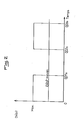
- Figure 2 shows an operating cycle of a solenoid valve. Considering that such a cycle extends over 0.02 seconds, and that in this cycle the solenoid valve works at full power for 0.01 seconds, that is to say during half of the cycle, and is at rest during the other half, the average flow rate of the solenoid valve on the cycle will be 50%, the solenoid valve will therefore have a duty factor of 50%.
- the duty cycle may vary slightly around the predetermined value.
- This duty cycle is adjusted from the setpoint value from the member 9 and from the position value from the sensor 7 by the comparator 8, and the operating frequency of the solenoid valves 1 and 2 is given by the generator. sawtooth 10 previously adjusted.
- the residual pulsations or residual vibrations can be eliminated, in accordance with the invention, by the provision of several solenoid valves mounted in parallel, the inputs and outputs of which are connected together, but whose electronic control members 3 and 4 have an offset to the supply equal to 2 ⁇ n representing the number of solenoid valves used, and this offset is obtained by means of a phase shift circuit 12 equipping each additional solenoid valve.
- the solenoid valve (s) used are of the 3-way - 2 position type, each of these solenoid valves being able to be replaced by an equivalent assembly of two solenoid valves of the 2-way type - 2 positions, one normally open and the other normally closed.
- the solenoid valve (s) used are of the 2-way - 2-position type.
- the invention it is possible to produce a current-flow converter with very rapid response, allowing very precise control of load handling devices, or the like, such as, in particular semi-automatic gearboxes of tractors. truckers, and the valves are very simple and can be easily replaced in the event of a fault.
- the device has a great flexibility of operation, and a rapid variation of the duty cycle between O and 100% is easily achievable, in particular thanks to the solenoid valves with lightened core.
- the device according to the invention is very reliable, the valves operating very well in a temperature range extending from - 20 ° C to + 80 ° C, and the electronic circuits, which are relatively simple, can be moved for their protection.
Abstract
Description
La présente invention concerne le domaine de l'asservissement de dispositifs de manoeuvre de charges, ou autres, ou de dispositifs de distribution, et a pour objet un convertisseur courant-débit à réponse rapide destiné à cet effet.The present invention relates to the field of servo-control of devices for operating loads, or the like, or of distribution devices, and has for its object a current-flow converter with fast response intended for this purpose.
Actuellement, les problèmes d'asservissement, tant pneumatique qu'hydraulique, de dispositifs de manoeuvre, ou de dispositifs de distribution, sont rendus possibles par l'utilisation de convertisseurs dans lesquels, à une grandeur d'entrée électrique donnée doit correspondre une pression ou un débit proportionnel. Dans de tels convertisseurs courant-débit sont généralement utilisés deux paramètres, à savoir, la pression d'alimentation, et la section de passage. Le débit d'air, ou l'interruption de ce débit, en direction du récepteur peuvent être réalisés, soit au moyen de vannes à fonctionnement analogique du type robinet, permettant une variation à l'infini du débit entre un maximum et un minimum, soit au moyen de vannes à fonctionnement logique du type électrovanne dont le débit est total ou nul suivant la position.Currently, the problems of servo-control, both pneumatic and hydraulic, of operating devices, or of distribution devices, are made possible by the use of converters in which, at a given electrical input quantity, must correspond a pressure or proportional flow. In such current-flow converters, two parameters are generally used, namely, the supply pressure, and the flow section. The air flow, or the interruption of this flow, towards the receiver can be achieved, either by means of valves with analog operation of the tap type, allowing an infinite variation of the flow between a maximum and a minimum, is by means of valves with logic operation of the solenoid valve type whose flow is total or zero according to the position.
L'utilisation de vannes motorisées permet une manoeuvre de charge, par exemple pour un déplacement, très précise, le débit pouvant être réglé par étranglement au moyen d'un moteur électrique agissant par l'intermédiaire d'un réducteur sur la vanne. Cependant, ce mode d'asservissement présente un temps de réponse relativement long ayant pour conséquence une inertie importante, de sorte que les variations brutales de débit sont pratiquement irréalisables.The use of motorized valves allows a load maneuver, for example for a very precise movement, the flow rate being adjustable by throttling by means of an electric motor acting via a reduction gear on the valve. However, this control mode has a relatively long response time, resulting in significant inertia, so that sudden variations in flow are practically impossible.
Il est également connu de réaliser un asservissement sensiblement analogique d'un dispositif de manoeuvre, ou de distribution, à partir d'électrovannes, qui sont des distributeurs logiques. A cet effet, plusieurs électrovannes ayant des débits différents, donc des diamètres de passage différents, sont regroupées en un groupe de distribution permettant l'obtention de plusieurs débits variant avec la ou les électrovannes utilisées. Cependant, le nombre de vitesses de manoeuvre possibles est directement fonction du nombre d'électrovannes employées, de sorte que pour une conversion relativement fine des débits, et donc des vitesses, le groupe de distribution devient relativement important, chaque électrovanne étant généralement suivie d'un étrangleur réglable.It is also known to produce a substantially analog servo of an operating device, or distribution, from solenoid valves, which are logic distributors. To this end, several solenoid valves having different flow rates, therefore different passage diameters, are grouped into a distribution group allowing the obtaining of several flow rates varying with the solenoid valve (s) used. However, the number of possible operating speeds is a direct function of the number of solenoid valves used, so that for a relatively fine conversion of the flow rates, and therefore of the speeds, the distribution group becomes relatively large, each solenoid valve being generally followed by an adjustable choke.
Pour la manoeuvre d'une charge sur un parcours linéaire, par exemple au moyen d'un vérin commandé par une électrovanne, l'interruption du déplacement du vérin, donc de son alimentation par l'électrovanne est commandée par un contact de fin de course actionné par la charge. Cependant, lorsque la charge agit sur le contact de fin de course, elle est douée d'une certaine vitesse et présente donc une certaine inertie due à sa masse, de sorte qu'elle dépasse sa position d'arrêt déterminée par ledit contact de fin de course. Il est donc nécessaire d'avancer le contact de fin de course pour anticiper l'arrêt de la charge. Un tel réglage empirique donne de bons résultats en laboratoire, mais ne peut être utilisé dans la pratique du fait des fluctuations possibles de la masse de la charge, ou de la pression d'alimentation. Une manoeuvre avec arrêt précis est possible en utilisant au moins deux électrovannes pour chaque sens de déplacement, à savoir une grosse électrovanne pour les déplacements rapides d'approche, et une petite électrovanne ou une électrovanne étranglée pour un arrêt précis à très petite vitesse. Cependant, notamment dans le cas d'un déplacement en va-et- vient, le dispositif d'asservissement devient relativement encombrant, et le réglage des contacts de fin de course devient difficile.For the operation of a load on a linear path, for example by means of a jack controlled by a solenoid valve, the interruption of the movement of the jack, therefore of its supply by the solenoid valve is controlled by a limit switch operated by the load. However, when the load acts on the limit switch, it is endowed with a certain speed and therefore has a certain inertia due to its mass, so that it exceeds its stop position determined by said contact. limit switch. It is therefore necessary to advance the limit switch to anticipate the load stopping. Such an empirical adjustment gives good results in the laboratory, but cannot be used in practice because of possible fluctuations in the mass of the charge, or in the supply pressure. Maneuvering with precise stop is possible by using at least two solenoid valves for each direction of movement, namely a large solenoid valve for rapid approach movements, and a small solenoid valve or a throttled solenoid valve for precise stop at very low speed. However, in particular in the case of a reciprocating movement, the control device becomes relatively bulky, and the adjustment of the limit switches becomes difficult.
Il est possible d'obvier à cet inconvénient en remplaçant les contacts de fin de course par des capteurs analogiques de déplacement, qui donnent à tout moment une indication de position du mobile à déplacer sous forme d'une information électrique. La commande automatique des électrovannes est alors réalisée au moyen d'un amplificateur opérationnel différentiel, qui effectue la différence entre une information électrique de consigne correspondant à la position requise du mobile et une information électrique provenant du capteur de position, correspondant à la position réelle instantanée du mobile. En présence d'un écart plus ou moins important entre les valeurs de consigne et de position réelle, la sortie de l'amplificateur commande, dans un sens de déplacement ou dans l'autre, l'une ou plusieurs des électrovannes concernées/afin de manoeuvrer le vérin en vue d'une réduction dudit écart, cette manoeuvre s'effectuant automatiquement, même en présence d'effets parasites extérieurs.It is possible to overcome this drawback by replacing the limit switches with analog displacement sensors, which give an indication of the position of the mobile to be moved at any time in the form of electrical information. The automatic control of the solenoid valves is then carried out by means of a differential operational amplifier, which makes the difference between a setpoint electrical information corresponding to the required position of the mobile and an electrical information coming from the position sensor, corresponding to the actual instantaneous position. of the mobile. In the presence of a more or less significant difference between the setpoint and actual position values, the output of the amplifier controls, in one direction of movement or the other, one or more of the solenoid valves concerned / in order to maneuver the actuator with a view to reducing said difference, this maneuver being carried out automatically, even in the presence of external parasitic effects.
Toutefois, ce mode d'asservissement entièrement électronique, en dehors du fait qu'il est relativement onéreux, ne permet pas d'obtenir un grand nombre de vitesses de manoeuvre, et occasionne ainsi un battement lors de la manoeuvre.However, this fully electronic control mode, apart from the fact that it is relatively expensive, does not make it possible to obtain a large number of maneuvering speeds, and thus causes a beat during the maneuver.
La présente invention a pour but de pallier les inconvénients des dispositifs d'asservissement connus.The present invention aims to overcome the drawbacks of known servo devices.
Elle a, en effet, pour objet un convertisseur courant-débit à réponse rapide, notamment pour l'asservissement de dispositifs de manoeuvre de charges, ou autres, ou de dispositifs de distribution, caractérisé en ce qu'il est essentiellement constitué par une ou plusieurs électrovannes de même type à fréquence de commutation rapide, commandées chacune par un organe de commande électronique, et raccordées par leur orifice d'entrée à un réservoir d'énergie, et par l'un de leurs orifices de sortie à un organe de manoeuvre de charge, tel qu'un vérin, par un capteur de position relié mécaniquement à l'organe de manoeuvre, et dont la sortie est reliée à un comparateur dont l'autre entrée est connectée à un organe donneur de signal de consigne, ce comparateur fournissant une tension qui est fonction directe de la différence entre valeur de consigne et valeur réelle, par un générateur de dents de scie relié à un détecteur de seuil connecté sur la sortie du comparateur, et qui compare le signal issu du générateur de dents de scie avec celui issu du comparateur, et, dans le cas de plusieurs électrovannes, d'une part, par un circuit de déphasage pour chaque électrovanne supplémentaire, et, d'autre part, par un siège de créneaux à rapport cyclique.It has, in fact, for its object a current-flow converter with rapid response, in particular for the servo-control of devices for operating loads, or the like, or of distribution devices, characterized in that it is essentially constituted by one or several solenoid valves of the same type with rapid switching frequency, each controlled by an electronic control member, and connected by their inlet orifice to an energy reservoir, and by one of their outlet orifices to an operating member load, such as a jack, by a position sensor mechanically connected to the operating member, and the output of which is connected to a comparator, the other input of which is connected to a setpoint signal-giving member, this comparator supplying a voltage which is a direct function of the difference between setpoint and actual value, by a sawtooth generator connected to a threshold detector connected to the output of the comparator, and which compares the signal i from the sawtooth generator with that from the comparator, and, in the case of several solenoid valves, on the one hand, by a phase shift circuit for each additional solenoid valve, and, on the other hand, by a slot seat with cyclical report.
Conformément à une caractéristique de l'invention, l'électrovanne à fréquence de commutation rapide ne comporte pas de spire de Frager, ni de tube amagnétique étanche, et est pourvue d'un noyau allégé, l'enroulement de cette électrovanne étant surdimensionné et suralimenté, par une alimentation à découpage donnant des impulsions sensiblement carrées, par l'intermédiaire de l'organe de commande électronique affecté à ladite électrovanne.According to a characteristic of the invention, the solenoid valve with fast switching frequency does not have a Frager turn, nor a sealed non-magnetic tube, and is provided with a lightened core, the winding of this solenoid valve being oversized and supercharged , by a switching power supply giving substantially square pulses, by means of the electronic control assigned to said solenoid valve.
L'invention sera mieux comprise grâce à la description ci-après, qui se rapporte à un mode de réalisation préféré, donné à titre d'exemple non limitatif, et expliqué avec référence aux dessins schématiques annexés, dans lesquels :
- la figure 1 est un schéma par blocs d'un dispositif conforme à l'invention, et
- la figure 2 est un schéma explicatif du facteur de marche.
- FIG. 1 is a block diagram of a device according to the invention, and
- Figure 2 is an explanatory diagram of the market factor.
Conformément à l'invention, et comme le montre, à titre d'exemple, la figure 1 des dessins annexés, le convertisseur courant-débit à réponse rapide pour l'asservissement de dispositifs de manoeuvre de charges, ou autres, est essentiellement constitué par des électrovannes 1 et 2 à fréquence de commutation rapide commandées respectivement par des organes de commande électroniques 3 et 4, par un réservoir d'énergie 5, tel qu'un réservoir à air comprimé, relié à l'orifice d'entrée des électrovannes 1 et 2, par un organe de manoeuvre de charge, tel qu'un vérin 6, relié à un orifice de sortie de chaque électrovanne 1 et 2, par un capteur de position 7 relié mécaniquement au vérin 6, par exemple à sa tige de piston, par un comparateur 8 relié, par ses entrées, respectivement à la sortie du capteur de position 7 et à la sortie d'un organe 9 donneur de signal de consigne, par un générateur de dents de scie 10 relié à un détecteur de seuil 11, dont l'autre entrée est reliée à la sortie du comparateur 8, par un circuit 12 de déphasage de l'électrovanne 2 et de son organe de commande 4, et par un siège C de créneaux à rapport cyclique.In accordance with the invention, and as shown, by way of example, in FIG. 1 of the appended drawings, the current-flow converter with rapid response for the control of load handling devices, or the like, essentially consists of
Chaque électrovanne 1 et 2 est avantageusement dépourvue de la spire de Frager, et son noyau est allégé et ne coulisse pas dans un tube amagnétique étanche, qui constituerait un frein magnétique, de sorte que ledit noyau peut être déplacé plus rapidement et qu'il présente i une inertie moindre.Each
Le débit des électrovannes 1 et 2 peut être varié par variation de leur facteur de marche, c'est-à-dire en les faisant fonctionner pendant un intervalle de temps déterminé, puis en les laissant au repos pendant un autre intervalle de temps. Ainsi, en réalisant un cycle marche- arrêt de même durée, le facteur de marche est de 50 %, et le débit moyen de l'électrovanne est égal à 50 % du débit maximum. Jusqu'à présent cette variation possible du débit était cependant accompagnée de pulsations sensibles de l'organe de manoeuvre de charge, du fait que les temps de commutation étaient relativement longs. Les électrovannes 1 et 2 selon l'invention permettent de pallier cet inconvénient du fait qu'elles présentent une fréquence de commutation élevée, de l'ordre de 100 Hz, et que leur enroulement, qui est surdimensionné, est suralimenté, en transitoire, par l'intermédiaire des organes de commande électroniques 3 et 4, par une alimentation à découpage donnant des impulsions sensiblement carrées, donc un front de montée rapide favorisant un mouvement rapide du noyau.The flow rate of the
En effet, il est nécessaire d'alimenter les électrovannes 1 et 2 au moyen d'une alimentation à découpage délivrant des impulsions sensiblement carrées, de manière à favoriser la croissance rapide du courant, donc du champ magnétique, au sein de ces électrovannes, sans provoquer trop de pertes fer.In fact, it is necessary to supply the
En outre, du fait de l'augmentation de la fréquence, la cadence de commutation augmente, et les vibrations peu sensibles qui subsistent sont annihilées du fait de l'inertie du vérin. En fonctionnement avec une électrovanne 3 voies - 2 positions, pour un facteur de marche voisin de 50 %, et une fréquence élevée, le vérin et la charge restent stationnaires. Si le facteur de marche augmente, le vérin sort à une vitesse qui s'accroît avec le facteur de marche, tandis que si ce dernier diminue en dessous de 50 %, le vérin sous charge rentre à une vitesse qui s'accroît en correspondance avec la diminution dudit facteur de marche.In addition, due to the increase in frequency, the switching rate increases, and the insensitive vibrations which remain are annihilated due to the inertia of the jack. In operation with a 3-way solenoid valve - 2 positions, for a duty factor close to 50%, and a high frequency, the actuator and the load remain stationary. If the duty factor increases, the cylinder exits at a speed which increases with the duty factor, while if the latter decreases below 50%, the jack under load returns at a speed which increases in correspondence with the decrease in said walk factor.
La figure 2 représente un cycle de fonctionnement d'une électrovanne. En considérant qu'un tel cycle s'étende sur 0,02 seconde, et que dans ce cycle l'électrovanne travaille à pleine puissance pendant 0,01 seconde, c'est-à-dire pendant la moitié du cycle, et soit au repos pendant l'autre moitié, le débit moyen de l'électrovanne sur le cycle sera de 50 %, l'électrovanne présentera donc un facteur de marche de 50 %.Figure 2 shows an operating cycle of a solenoid valve. Considering that such a cycle extends over 0.02 seconds, and that in this cycle the solenoid valve works at full power for 0.01 seconds, that is to say during half of the cycle, and is at rest during the other half, the average flow rate of the solenoid valve on the cycle will be 50%, the solenoid valve will therefore have a duty factor of 50%.
Bien entendu, les explications ci-dessus ne tiennent pas compte des diverses pertes mécaniques, le facteur de marche pouvant légèrement varier autour de la valeur prédéterminée.Of course, the above explanations do not take into account the various mechanical losses, the duty cycle may vary slightly around the predetermined value.
Ce facteur de marche est réglé à partir de la valeur de consigne issue dé l'organe 9 et de la valeur de position issue du capteur 7 par le comparateur 8, et la fréquence de fonctionnement des électrovannes 1 et 2 est donnée par le générateur de dents de scie 10 préalablement ajusté.This duty cycle is adjusted from the setpoint value from the member 9 and from the position value from the
Les pulsations ou vibrations résiduelles subsistantes peuvent être éliminées, conformément à l'invention, par la prévision de plusieurs électrovannes montées eh parallèle, dont les entrées et les sorties sont reliées ensemble, mais dont les organes de commande électroniques 3 et 4 présentent un décalage à l'alimentation égal à 2π n représentant le nombre d'électrovannes utilisées, et ce décalage est obtenu grâce à un circuit de déphasage 12 équipant chaque électrovanne supplémentaire.The residual pulsations or residual vibrations can be eliminated, in accordance with the invention, by the provision of several solenoid valves mounted in parallel, the inputs and outputs of which are connected together, but whose
Conformément à une caractéristique de l'invention, dans le cas de l'asservissement de dispositifs de manoeuvre, la ou les électrovannes utilisées sont du type 3 voies - 2 positions, chacune de ces électrovannes pouvant être remplacée par un montage équivalent de deux électrovannes du type 2 voies - 2 positions, l'une étant normalement ouverte et l'autre normalement fermée.According to a characteristic of the invention, in the case of the control of operating devices, the solenoid valve (s) used are of the 3-way - 2 position type, each of these solenoid valves being able to be replaced by an equivalent assembly of two solenoid valves of the 2-way type - 2 positions, one normally open and the other normally closed.
Selon une autre caractéristique de l'invention, dans le cas de l'asservissement de dispositifs de distribution, la ou les électrovannes utilisées sont du type 2 voies - 2 positions.According to another characteristic of the invention, in the case of the control of distribution devices, the solenoid valve (s) used are of the 2-way - 2-position type.
Le fonctionnement du dispositif représenté aux dessins annexés s'effectue de la manière suivante :
- Lors de la mise en marche du dispositif, le
capteur 7 délivre une valeur de position réelle qui est transmise aucomparateur 8, qui fournit une tension, qui est fonction directe de la différence entre une valeur de consigne donnée par l'organe 9 et la valeur de position. Cette tension est comparée dans le détecteur deseuil 11 avec les dents de scie fournies par legénérateur 10, et le signal de sortie dudétecteur 11 est transmis, comme signal de commande, à l'organe 3 de commande de l'électrovanne 1, et, après passage par le circuit de déphasage 12, à l'organe 4 de commande de l'électrovanne 2, le point C étant le siège de créneaux à rapport cyclique issus dudétecteur 11.
- When the device is switched on, the
sensor 7 delivers an actual position value which is transmitted to thecomparator 8, which supplies a voltage, which is a direct function of the difference between a set value given by the member 9 and the position value. This voltage is compared in thethreshold detector 11 with the saw teeth provided by thegenerator 10, and the output signal of thedetector 11 is transmitted, as a control signal, to thecontrol member 3 of thesolenoid valve 1, and, after passing through the phase shift circuit 12, to themember 4 for controlling thesolenoid valve 2, the point C being the seat of slots with cyclic ratio originating from thedetector 11.
Conformément à une caractéristique de l'invention, il est également possible de réduire les pulsations ou vibrations, sans augmenter la fréquence d'alimentation des électrovannes, en multipliant celles-ci par n, et si le débit doit rester constant, en réduisant leur diamètre de passage par V-n.According to a characteristic of the invention, it is also possible to reduce the pulsations or vibrations, without increasing the frequency of supply of the solenoid valves, by multiplying them by n, and if the flow rate must remain constant, by reducing their diameter passing through Vn.
Il est également possible, selon une autre caractéristique de l'invention, de réaliser une conversion courant-gros débit en reliant un vérin, commandé par la ou les électrovannes du convertisseur, au tiroir de commande d'un gros distributeur.It is also possible, according to another characteristic of the invention, to carry out a current-to-large flow conversion by connecting a jack, controlled by the solenoid valve (s) of the converter, to the control slide of a large distributor.
Grâce à l'invention, il est possible de réaliser un convertisseur courant-débit à réponse très rapide, permettant l'asservissement très précis de dispositifs de manoeuvre de charges, ou autres, tels que, notamment des boîtes de vitesse semi-automatiques de tracteurs routiers, et dont les vannes sont très simples et peuvent être facilement remplacées en cas de défaut. En outre, le dispositif présente une grande souplesse de fonctionnement, et une variation rapide du facteur de marche entre O et 100 % est facilement réalisable, en particulier grâce aux électrovannes à noyau allégé. Enfin, le dispositif conforme à l'invention est très fiable, les vannes fonctionnant très bien dans une plage de température s'étendant de - 20° C à + 80° C, et les circuits électroniques, qui sont relativement simples, pouvant être déplacés pour leur protection.Thanks to the invention, it is possible to produce a current-flow converter with very rapid response, allowing very precise control of load handling devices, or the like, such as, in particular semi-automatic gearboxes of tractors. truckers, and the valves are very simple and can be easily replaced in the event of a fault. In addition, the device has a great flexibility of operation, and a rapid variation of the duty cycle between O and 100% is easily achievable, in particular thanks to the solenoid valves with lightened core. Finally, the device according to the invention is very reliable, the valves operating very well in a temperature range extending from - 20 ° C to + 80 ° C, and the electronic circuits, which are relatively simple, can be moved for their protection.
En outre, grâce aux électrovannes conformes à l'invention, et à la variation du facteur de marche, il est possible de réaliser l'asservissement de dispositifs de distribution, par exemple de liquides ou de gaz, notamment dans le domaine de la chimie, en vue de la réalisation de mélanges de fluides, ou autres, avec un grand degré de précision, le capteur de position étant alors remplacé, par exemple, par un débitmètre.In addition, thanks to the solenoid valves according to the invention, and to the variation of the duty cycle, it is possible to control the distribution devices, for example liquids or gases, in particular in the field of chemistry, with a view to producing mixtures of fluids, or the like, with a high degree of precision, the position sensor then being replaced, for example, by a flow meter.
Bien entendu, l'invention n'est pas limitée au mode de réalisation décrit et représenté au dessin annexé. Des modifications restent possibles, notamment du point de vue de la constitution des divers éléments, ou par substitution d'équivalents techniques, sans sortir pour autant du domaine de protection de l'invention.Of course, the invention is not limited to the embodiment described and shown in the accompanying drawing. Modifications remain possible, in particular from the point of view of the constitution of the various elements, or by substitution of technical equivalents, without thereby departing from the scope of protection of the invention.
Claims (5)
Priority Applications (1)
| Application Number | Priority Date | Filing Date | Title |
|---|---|---|---|
| AT81440017T ATE15928T1 (en) | 1980-06-10 | 1981-06-09 | FAST RESPONDING FLOW-CURRENT CONVERTER, PARTICULARLY FOR CONTROL OF ACTUATORS OR DISTRIBUTION DEVICES. |
Applications Claiming Priority (2)
| Application Number | Priority Date | Filing Date | Title |
|---|---|---|---|
| FR8013347 | 1980-06-10 | ||
| FR8013347A FR2484106A1 (en) | 1980-06-10 | 1980-06-10 | FAST-RESPONSE CURRENT-FLOW CONVERTER, IN PARTICULAR FOR THE LOADING OF LOADING DEVICES, OR OTHERWISE, OR DISTRIBUTION DEVICES |
Publications (2)
| Publication Number | Publication Date |
|---|---|
| EP0044263A1 true EP0044263A1 (en) | 1982-01-20 |
| EP0044263B1 EP0044263B1 (en) | 1985-10-02 |
Family
ID=9243142
Family Applications (1)
| Application Number | Title | Priority Date | Filing Date |
|---|---|---|---|
| EP81440017A Expired EP0044263B1 (en) | 1980-06-10 | 1981-06-09 | Quick response flow-current converter, especially to control actuation or distribution devices |
Country Status (4)
| Country | Link |
|---|---|
| EP (1) | EP0044263B1 (en) |
| AT (1) | ATE15928T1 (en) |
| DE (1) | DE3172501D1 (en) |
| FR (1) | FR2484106A1 (en) |
Cited By (2)
| Publication number | Priority date | Publication date | Assignee | Title |
|---|---|---|---|---|
| EP0091018A1 (en) * | 1982-04-01 | 1983-10-12 | Deere & Company | Position control for a double acting hydraulic motor |
| USRE33846E (en) * | 1982-04-01 | 1992-03-17 | Deere & Company | Electrohydraulic valve system |
Citations (6)
| Publication number | Priority date | Publication date | Assignee | Title |
|---|---|---|---|---|
| US3279323A (en) * | 1964-09-28 | 1966-10-18 | North American Aviation Inc | Electrohydraulic actuator |
| US3295421A (en) * | 1964-03-16 | 1967-01-03 | Loran F Mccormick | Position control circuit |
| US3521535A (en) * | 1967-11-07 | 1970-07-21 | Chandler Evans Inc | Time modulated pneumatically actuated position control mechanism |
| US3659631A (en) * | 1970-08-05 | 1972-05-02 | Moore Business Forms Inc | Controller for a pulsed servovalve |
| US3740588A (en) * | 1969-12-08 | 1973-06-19 | Gen Electric | Time ratio switching control system |
| US4015426A (en) * | 1972-11-20 | 1977-04-05 | Nippondenso Co., Ltd. | Fuel control system |
Family Cites Families (2)
| Publication number | Priority date | Publication date | Assignee | Title |
|---|---|---|---|---|
| US3561326A (en) * | 1968-03-06 | 1971-02-09 | Parker Hannifin Corp | Pulse phase modulated servoactuator |
| DE2203036A1 (en) * | 1971-02-10 | 1972-08-17 | Elektro App Werke Berlin Inst | Adjusting device |
-
1980
- 1980-06-10 FR FR8013347A patent/FR2484106A1/en active Granted
-
1981
- 1981-06-09 AT AT81440017T patent/ATE15928T1/en not_active IP Right Cessation
- 1981-06-09 EP EP81440017A patent/EP0044263B1/en not_active Expired
- 1981-06-09 DE DE8181440017T patent/DE3172501D1/en not_active Expired
Patent Citations (6)
| Publication number | Priority date | Publication date | Assignee | Title |
|---|---|---|---|---|
| US3295421A (en) * | 1964-03-16 | 1967-01-03 | Loran F Mccormick | Position control circuit |
| US3279323A (en) * | 1964-09-28 | 1966-10-18 | North American Aviation Inc | Electrohydraulic actuator |
| US3521535A (en) * | 1967-11-07 | 1970-07-21 | Chandler Evans Inc | Time modulated pneumatically actuated position control mechanism |
| US3740588A (en) * | 1969-12-08 | 1973-06-19 | Gen Electric | Time ratio switching control system |
| US3659631A (en) * | 1970-08-05 | 1972-05-02 | Moore Business Forms Inc | Controller for a pulsed servovalve |
| US4015426A (en) * | 1972-11-20 | 1977-04-05 | Nippondenso Co., Ltd. | Fuel control system |
Cited By (2)
| Publication number | Priority date | Publication date | Assignee | Title |
|---|---|---|---|---|
| EP0091018A1 (en) * | 1982-04-01 | 1983-10-12 | Deere & Company | Position control for a double acting hydraulic motor |
| USRE33846E (en) * | 1982-04-01 | 1992-03-17 | Deere & Company | Electrohydraulic valve system |
Also Published As
| Publication number | Publication date |
|---|---|
| DE3172501D1 (en) | 1985-11-07 |
| FR2484106A1 (en) | 1981-12-11 |
| ATE15928T1 (en) | 1985-10-15 |
| EP0044263B1 (en) | 1985-10-02 |
| FR2484106B1 (en) | 1983-04-01 |
Similar Documents
| Publication | Publication Date | Title |
|---|---|---|
| EP1669648B1 (en) | Motor operated valve | |
| FR2551520A1 (en) | DEVICE FOR CONTROLLING THE REPORT OF A CONTINUOUS VARIATION TRANSMISSION | |
| FR2528502A1 (en) | HYDRAULIC CONTROL DEVICE | |
| FR2458725A1 (en) | ELECTRONIC DEVICE FOR CONTROLLING THE BRIDGE OF A HYDRODYNAMIC TORQUE CONVERTER AND METHOD OF IMPLEMENTING THE SAME | |
| EP0194927B1 (en) | Pressure control servo device for a hydraulic installation, particularly for vehicle servo steering | |
| EP0022833B1 (en) | Electrohydraulic transducer, especially for controlling a pressure in an automatic transmission | |
| EP0044263A1 (en) | Quick response flow-current converter, especially to control actuation or distribution devices | |
| FR2654197A1 (en) | CONTROL DEVICE FOR INSTALLATION FOR ADJUSTING THE VENTILATION FLOW OF A PREMISES WITH A CONTROLLED ATMOSPHERE AND OPERATING CYCLE. | |
| EP2150380A2 (en) | Percussion device actuated by a pressurised non compressible fluid | |
| FR2488332A1 (en) | HYDRAULIC SYSTEM FOR DYNAMOMETRIC BRAKING AND FOR ENERGY RECOVERY OF HEAT ENGINES DURING TESTS WITH AC PRODUCTION | |
| FR2582797A1 (en) | BRAKING AND RELEASING DEVICE FOR A ROTARY TUBE BODY FOR GUIDING A FLYING VEHICLE | |
| FR2717252A1 (en) | Installation equipped with an automatic system for adjusting a heating. | |
| FR2546983A1 (en) | Hydraulic valve system for priority motor | |
| EP0560657B1 (en) | Energy transmission device for a mechanical control, particularly to control the braking pressure in a brake | |
| FR2738876A1 (en) | ELECTRO-PNEUMATIC SYSTEM | |
| FR2481763A1 (en) | ELECTRO-HYDRAULIC ADJUSTMENT CONTROL | |
| EP0434490B1 (en) | Working control device for two internal combustion engines both linked with a common alternator driving axis | |
| EP0186596B1 (en) | Linear displacement control system comprising a dc motor | |
| EP0750241A2 (en) | Hydraulic flow controller | |
| CH286240A (en) | Method for stabilizing the operation of a hydroelectric installation and device allowing the implementation of said method. | |
| FR2563289A1 (en) | SERVO VALVE CONTROL DEVICE | |
| FR2486692A1 (en) | ASSEMBLY FOR PROVIDING FLUID SIGNALS | |
| CH343485A (en) | Remote control device | |
| BE554138A (en) | ||
| FR2655390A1 (en) | PNEUMATIC DEVICE, TIMED PULSE GENERATOR OF GAS. |
Legal Events
| Date | Code | Title | Description |
|---|---|---|---|
| PUAI | Public reference made under article 153(3) epc to a published international application that has entered the european phase |
Free format text: ORIGINAL CODE: 0009012 |
|
| AK | Designated contracting states |
Designated state(s): AT BE CH DE GB IT LU NL SE |
|
| 17P | Request for examination filed |
Effective date: 19811230 |
|
| PGFP | Annual fee paid to national office [announced via postgrant information from national office to epo] |
Ref country code: FR Payment date: 19840619 Year of fee payment: 4 |
|
| GRAA | (expected) grant |
Free format text: ORIGINAL CODE: 0009210 |
|
| AK | Designated contracting states |
Designated state(s): AT BE CH DE GB IT LI LU NL SE |
|
| PG25 | Lapsed in a contracting state [announced via postgrant information from national office to epo] |
Ref country code: IT Free format text: LAPSE BECAUSE OF FAILURE TO SUBMIT A TRANSLATION OF THE DESCRIPTION OR TO PAY THE FEE WITHIN THE PRESCRIBED TIME-LIMIT;WARNING: LAPSES OF ITALIAN PATENTS WITH EFFECTIVE DATE BEFORE 2007 MAY HAVE OCCURRED AT ANY TIME BEFORE 2007. THE CORRECT EFFECTIVE DATE MAY BE DIFFERENT FROM THE ONE RECORDED. Effective date: 19851002 |
|
| REF | Corresponds to: |
Ref document number: 15928 Country of ref document: AT Date of ref document: 19851015 Kind code of ref document: T |
|
| REF | Corresponds to: |
Ref document number: 3172501 Country of ref document: DE Date of ref document: 19851107 |
|
| PG25 | Lapsed in a contracting state [announced via postgrant information from national office to epo] |
Ref country code: LU Free format text: LAPSE BECAUSE OF NON-PAYMENT OF DUE FEES Effective date: 19860630 |
|
| PLBE | No opposition filed within time limit |
Free format text: ORIGINAL CODE: 0009261 |
|
| STAA | Information on the status of an ep patent application or granted ep patent |
Free format text: STATUS: NO OPPOSITION FILED WITHIN TIME LIMIT |
|
| 26N | No opposition filed | ||
| PGFP | Annual fee paid to national office [announced via postgrant information from national office to epo] |
Ref country code: GB Payment date: 19900608 Year of fee payment: 10 |
|
| PGFP | Annual fee paid to national office [announced via postgrant information from national office to epo] |
Ref country code: AT Payment date: 19900613 Year of fee payment: 10 |
|
| PGFP | Annual fee paid to national office [announced via postgrant information from national office to epo] |
Ref country code: CH Payment date: 19900614 Year of fee payment: 10 |
|
| PGFP | Annual fee paid to national office [announced via postgrant information from national office to epo] |
Ref country code: SE Payment date: 19900615 Year of fee payment: 10 |
|
| PGFP | Annual fee paid to national office [announced via postgrant information from national office to epo] |
Ref country code: DE Payment date: 19900618 Year of fee payment: 10 |
|
| PGFP | Annual fee paid to national office [announced via postgrant information from national office to epo] |
Ref country code: LU Payment date: 19900628 Year of fee payment: 10 |
|
| PGFP | Annual fee paid to national office [announced via postgrant information from national office to epo] |
Ref country code: NL Payment date: 19900630 Year of fee payment: 10 |
|
| PGFP | Annual fee paid to national office [announced via postgrant information from national office to epo] |
Ref country code: BE Payment date: 19900704 Year of fee payment: 10 |
|
| PG25 | Lapsed in a contracting state [announced via postgrant information from national office to epo] |
Ref country code: GB Effective date: 19910609 Ref country code: AT Effective date: 19910609 |
|
| PG25 | Lapsed in a contracting state [announced via postgrant information from national office to epo] |
Ref country code: SE Effective date: 19910610 |
|
| PG25 | Lapsed in a contracting state [announced via postgrant information from national office to epo] |
Ref country code: LI Effective date: 19910630 Ref country code: CH Effective date: 19910630 Ref country code: BE Effective date: 19910630 |
|
| BERE | Be: lapsed |
Owner name: GUETTMANN PIERRE Effective date: 19910630 |
|
| PG25 | Lapsed in a contracting state [announced via postgrant information from national office to epo] |
Ref country code: NL Effective date: 19920101 |
|
| GBPC | Gb: european patent ceased through non-payment of renewal fee | ||
| NLV4 | Nl: lapsed or anulled due to non-payment of the annual fee | ||
| REG | Reference to a national code |
Ref country code: CH Ref legal event code: PL |
|
| PG25 | Lapsed in a contracting state [announced via postgrant information from national office to epo] |
Ref country code: DE Effective date: 19920401 |
|
| EUG | Se: european patent has lapsed |
Ref document number: 81440017.2 Effective date: 19920109 |