EP0054584A1 - Broadband antenna system - Google Patents
Broadband antenna system Download PDFInfo
- Publication number
- EP0054584A1 EP0054584A1 EP80201214A EP80201214A EP0054584A1 EP 0054584 A1 EP0054584 A1 EP 0054584A1 EP 80201214 A EP80201214 A EP 80201214A EP 80201214 A EP80201214 A EP 80201214A EP 0054584 A1 EP0054584 A1 EP 0054584A1
- Authority
- EP
- European Patent Office
- Prior art keywords
- draw
- aerial
- view
- elements
- type
- Prior art date
- Legal status (The legal status is an assumption and is not a legal conclusion. Google has not performed a legal analysis and makes no representation as to the accuracy of the status listed.)
- Withdrawn
Links
Images


Classifications
-
- H—ELECTRICITY
- H01—ELECTRIC ELEMENTS
- H01Q—ANTENNAS, i.e. RADIO AERIALS
- H01Q9/00—Electrically-short antennas having dimensions not more than twice the operating wavelength and consisting of conductive active radiating elements
- H01Q9/04—Resonant antennas
- H01Q9/44—Resonant antennas with a plurality of divergent straight elements, e.g. V-dipole, X-antenna; with a plurality of elements having mutually inclined substantially straight portions
Definitions
- the invention applies to a wide range system for the reception of radiowaves for the FM band and the other wave-frequences , and for the reception of Television image lines on the VHF/UHF channels and/or other signals an aerial can be used for.
- Radiowaves and TV image lines usually take place through apole on which Rasters and Dipoles in varions shapes and sizes are installed, those must be pointed on the senders that transmit the signals.
- the Radiowaves and TV image lines are received by an aerial.
- the aerial only receives the signals well when it is pointed directly to the transmitting-station, and when the aerial is placed in a way that there are no obstacles between the transmitter and the receiver; like Sky-scrapers, Buildingsteel, and/or other constructions that could have an influence on the transmitted signals.
- Radiowaves and TV image lines depend with today's system very much of other disturbing elements like Planes, Cars, Motorbikes, all kind of Machineries and Climat conditions (atmospherics).
- the aerialsystems for Radio and TV used so far have some more disadvantages: the immense maintenance need, the space occupancy and the disfigurement.
- the goal of this invention is to come up whit an aerial system that, without affecting the quality of picture and sound, will avoid the said disadvantages. While constructing an aerial according to the described invention and the drawings enclosed, this goal is reacted.
- the wide range aerialsystem i constructed from a number of elements made from alumiumbars of round 4mm-that is 0.16 inch in section- to get the sensibility as high as possible and the weight as low as possible.
- the aerial other materials can be used too, like; Spring- steel, Copper and Brass. All these materials the elements can be made from.
- the position of the Dipoles assure that these elements will receive transmitted signals, incoming trough the elements E-J-K-L- and M are transmitted to a steeringscreen (draw.XGI).
- This screen takes care that the pictures (signals) and waves to be recived are free from reflection and other disturbing elements.
- the signals enter the housing of the elements,where they are connected to 4 element-holders.
- the signals are transmitted to a series of prints that take care for the following transmitting of the signals.
- the prints are connected and linked by means of a Pole connectionfilter with 2 tubetrimmers avoiding an overload of signals on the exitsignal of the aerial. Otherwise an overload could enter the receiver and disturb the picture.
- the prints also can be omitted.
- the parts are placed in the housing without connection, which is possible because after the assembling the housing will be filled with cast resin or epoxyresin resulting in a definite separation of the elements and avoiding internal failures.
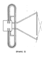
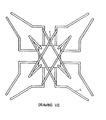
- FIG. 1 show the side-views of the aerial types A-B-C-D and E, while the drawings II-IV-V-VI and VII show the top-views of the different types.
- the elements of above mentioned aerials are made- from a certain kind of Duralmin Alumium, where the bars round 4mm are made from .
- Alumium is chosen because of the different atmos- feric influences. Depending on the circumstances also other materials can be used-some of them are mentioned before.Both thicker and thinner types are useful depending on the demands made and the chosen possibilities.
- the elements L (see draw. XII L) are placed in an element-holder acc. to drawing IX A. Over or under this holder the elements J and K are installed ( draw. XI J and XII K).
- connectionfilter draw. XI H
- print G I draw.X G I
- tow trimmers are placed on print III (draw. X III).
- the elements M are placed (draw. XIII M) on the print II and III (draw. X GII and GIII), after that the trimmers are assembled and connected. After assembling and casting a lid (draw. XI I) is placed and the unit is ready now for the setting and control procedures.
- the aerial After checking the reception of Radiowaves and TV image lines the aerial is ready for installation.
- the aerial can be installed in many ways. It depends on the situation of the object the aerial has to be placed on.
Landscapes
- Aerials With Secondary Devices (AREA)
Abstract
The broadband antenna system here considered and assembled from the elements described, is serving for the reception of signals for Radio and Television.
The special features are:
- the compactness,
- the reception of signals from every direction,
- the insensibility for disturbing elements and climat conditions (atmosferics),
- the versatility and easy managebility,
- weak signals produce a good picture and sound, both for black/white and color TV without the use of separate amplifiers.
With this invention it has to be postulated that the described aerial can be used as a replacement for the TV-and Radioaerialsystem of today, that are so disfiguring our environment and that need so much space.
On places outside the transmitting field of a transmitter also this aerial on limited height will not be able to make the signals visable.
Description
- The invention applies to a wide range system for the reception of radiowaves for the FM band and the other wave-frequences , and for the reception of Television image lines on the VHF/UHF channels and/or other signals an aerial can be used for.
- Up to the present the reception of Radiowaves and TV image lines usually take place through apole on which Rasters and Dipoles in varions shapes and sizes are installed, those must be pointed on the senders that transmit the signals.
- The Radiowaves and TV image lines are received by an aerial. The aerial only receives the signals well when it is pointed directly to the transmitting-station, and when the aerial is placed in a way that there are no obstacles between the transmitter and the receiver; like Sky-scrapers, Buildingsteel, and/or other constructions that could have an influence on the transmitted signals.
- Beside the need that the aerial is pointed very well to the transmitter, the quality of the receiption of Radiowaves and TV image lines depends with today's system very much of other disturbing elements like Planes, Cars, Motorbikes, all kind of Machineries and Climat conditions (atmospherics).
- The above mentioned circumstances can have ahuge influence on the reception possibilities of Radiowaves and TV image lines. With today's system without amplification there is also the need that the transmitted signals for Television must have a minimal power of 15-25 dB to enable an acceptable reception of the signals.
- The aerialsystems for Radio and TV used so far have some more disadvantages: the immense maintenance need, the space occupancy and the disfigurement.
- The goal of this invention is to come up whit an aerial system that, without affecting the quality of picture and sound, will avoid the said disadvantages. While constructing an aerial according to the described invention and the drawings enclosed, this goal is reacted.
- It has to be postulated that the aerial described here must be seen as a replacement for today's systems for the reception of Radiowaves and TV image lines that disfigure our envirement so much.
- The discription deals mainly with the principle of TV waves, but the same thing applies- and even in equal proportions- for Radiowaves with all its possible channels.
- The wide range aerialsystem i constructed from a number of elements made from alumiumbars of round 4mm-that is 0.16 inch in section- to get the sensibility as high as possible and the weight as low as possible. For the construction of the aerial other materials can be used too, like; Spring- steel, Copper and Brass. All these materials the elements can be made from.
- The position of the Dipoles assure that these elements will receive transmitted signals, incoming trough the elements E-J-K-L- and M are transmitted to a steeringscreen (draw.XGI).
- This screen takes care that the pictures (signals) and waves to be recived are free from reflection and other disturbing elements.
- It is very important that even signals with a power of only afew decibels can be received and than be amplified in such a way-by means of the construction of the elements-that they can be transmitted as well visible picture.
- This is in direct contrast with today's system, while now amplifying elements and amplifurs nears the aerial are needed to make weak and bad TV inmage lines receivable and usefull for reproduction.
- Through an insulated system the signals enter the housing of the elements,where they are connected to 4 element-holders. Next the signals are transmitted to a series of prints that take care for the following transmitting of the signals. The prints are connected and linked by means of a Pole connectionfilter with 2 tubetrimmers avoiding an overload of signals on the exitsignal of the aerial. Otherwise an overload could enter the receiver and disturb the picture.
- With the 2 tubetrimmers and connectionfilter installed,it is possible to create a power stability of fio-75 ohM. Without further arrangements the aerial so can be connected to the existing coaxcable and is therefore also usable for all aerial junctions, even for all thenow existing aerialsystems in every design and construction.
- Depending on the type and construction of the aerial, the prints also can be omitted. In that case the parts are placed in the housing without connection, which is possible because after the assembling the housing will be filled with cast resin or epoxyresin resulting in a definite separation of the elements and avoiding internal failures.
- In certain cases an amplifier will be needed and if so, during the assembling this has to be taken in to account. Although there are several possibilities, the best resuts you get with a pole amplifier mounted an a print within the housing (OM 335 DMT).
- As shown on the drawings there are different desings of the aerial available. Living close to the transmitters sometimes one single element is sufficient, of course depending on the demands made and the given possibilities of the receivable channels.
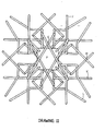
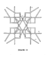
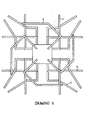
- The drawings I and III show the side-views of the aerial types A-B-C-D and E, while the drawings II-IV-V-VI and VII show the top-views of the different types. The elements of above mentioned aerials are made- from a certain kind of Duralmin Alumium, where the bars round 4mm are made from .
- For this kind of Alumium is chosen because of the different atmos- feric influences. Depending on the circumstances also other materials can be used-some of them are mentioned before.Both thicker and thinner types are useful depending on the demands made and the chosen possibilities.
- The elements L (see draw. XII L) are placed in an element-holder acc. to drawing IX A. Over or under this holder the elements J and K are installed ( draw. XI J and XII K).
- In the top of the elementholder the elements E (draw. IX E ) are screwed. At the bottom the print or steerigscreen is mounted using 4 treads M4, making it one unit according to draw. IX E and X I.
- There is a possibility that in the final production the element- holder and the elements E will be producted like one single unit (see draw. IX A and IX E).
- The two long mountingpins of the connectionfilter (draw. XI H) are passed through the two prints (draw. X GII and GIII) and assembled on print G I (draw.X G I) there after the tow trimmers are placed on print III (draw. X III).
- Before the assembling the whole construction however has to be placed in the housing (draw. X F). After wards this housing is filled up with cast- or epoxy-resin.
- Depending on the type, the elements M are placed (draw. XIII M) on the print II and III (draw. X GII and GIII), after that the trimmers are assembled and connected. After assembling and casting a lid (draw. XI I) is placed and the unit is ready now for the setting and control procedures.
- After checking the reception of Radiowaves and TV image lines the aerial is ready for installation. The aerial can be installed in many ways. It depends on the situation of the object the aerial has to be placed on.
- For that reason there are a lot of mounting possibilities, for instance shortening the pole of the existing aerial iafter removing the aerial) in such a wav that tha new aerial just reses above the roof. Another way is to install this type of aerial on an attie. It is advised to determine the best place for the aerial with the help of a measuring receiver.
Claims (3)
1 The required claims we ask for intend to be for all drawings and all types of this WIDE RANGE AERIAL SYSTEM.
It also has be taken in to account that from the steeringsscreen there are many many more possibilities for the connection of the aerial to the receiving-unit.
So it is possible that there will be many changes in the connection possibilities, because there are so many, and especially we think of the field of the Central Aerial System.
Draw. I - Side-view of the Aerial type A.
Draw. II - Top-view of the Aerial type A.
Draw. III - Side-view of the Aerial type B-C-D- and E.
Draw. IV - Top-view of the Aerial type B.
Draw. V - Top-view of the Aerial type C.
Draw. VI - Top-view of the Aerial type D
Draw. VII - Top-view of the Aerial type E.
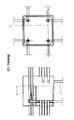
Draw. VIII - View and section of the housing.
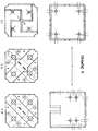
Draw. IX - A-Elementholder.
- B-Separationpipe for the prints
- C-Distanceinsulater for the elements.
- D-Fancy and insulationcap for the elem. E.
- E-FM elements suitable for placing in different corners.
Draw. X - F-Bottom and side-view of the housing, to be made from PVC or another synthetic material not be become static.
- GI-Print for the elementholder and the pole connectionfilter, also in use as a steeringscreen.
- GII-The connectionprint for the steeringscreen/mk filter and the two tubetrimmers.
-GIII-Print for the two M elements in use for aerial type A.
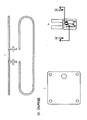
Draw. XI -H-Connectionfilter including 2 tubetrimmers for setting the outgoing power. -I-The lid for the housing F.
-J-The big Dipole for the reception of channels 1-70. Draw. XII -K-The small Dipole for the channels 1-70. -L-The elements in use for the channels 12-70.The set- corner of this elements can differ from 0 to 180 degrees.
Draw. XIII -M-The connection elements in use for all channels, but on the drawing only placed in type A.
Priority Applications (1)
| Application Number | Priority Date | Filing Date | Title |
|---|---|---|---|
| EP80201214A EP0054584A1 (en) | 1980-12-19 | 1980-12-19 | Broadband antenna system |
Applications Claiming Priority (1)
| Application Number | Priority Date | Filing Date | Title |
|---|---|---|---|
| EP80201214A EP0054584A1 (en) | 1980-12-19 | 1980-12-19 | Broadband antenna system |
Publications (1)
| Publication Number | Publication Date |
|---|---|
| EP0054584A1 true EP0054584A1 (en) | 1982-06-30 |
Family
ID=8187060
Family Applications (1)
| Application Number | Title | Priority Date | Filing Date |
|---|---|---|---|
| EP80201214A Withdrawn EP0054584A1 (en) | 1980-12-19 | 1980-12-19 | Broadband antenna system |
Country Status (1)
| Country | Link |
|---|---|
| EP (1) | EP0054584A1 (en) |
Citations (5)
| Publication number | Priority date | Publication date | Assignee | Title |
|---|---|---|---|---|
| US2780808A (en) * | 1953-12-15 | 1957-02-05 | Marvin P Middlemark | High frequency antennas |
| GB1024367A (en) * | 1962-10-04 | 1966-03-30 | Siemens Ag | Aerial arrays for electromagnetic-wave radiation |
| US3932874A (en) * | 1974-09-11 | 1976-01-13 | Rca Corporation | Broadband turnstile antenna |
| US4030101A (en) * | 1974-09-06 | 1977-06-14 | Kazuhisa Satoh | Regular eight face polyhedral antenna element |
| US4083051A (en) * | 1976-07-02 | 1978-04-04 | Rca Corporation | Circularly-polarized antenna system using tilted dipoles |
-
1980
- 1980-12-19 EP EP80201214A patent/EP0054584A1/en not_active Withdrawn
Patent Citations (5)
| Publication number | Priority date | Publication date | Assignee | Title |
|---|---|---|---|---|
| US2780808A (en) * | 1953-12-15 | 1957-02-05 | Marvin P Middlemark | High frequency antennas |
| GB1024367A (en) * | 1962-10-04 | 1966-03-30 | Siemens Ag | Aerial arrays for electromagnetic-wave radiation |
| US4030101A (en) * | 1974-09-06 | 1977-06-14 | Kazuhisa Satoh | Regular eight face polyhedral antenna element |
| US3932874A (en) * | 1974-09-11 | 1976-01-13 | Rca Corporation | Broadband turnstile antenna |
| US4083051A (en) * | 1976-07-02 | 1978-04-04 | Rca Corporation | Circularly-polarized antenna system using tilted dipoles |
Similar Documents
| Publication | Publication Date | Title |
|---|---|---|
| US7289062B2 (en) | Method and device for accurately pointing a satellite earth station antenna | |
| US6216266B1 (en) | Remote control signal level meter | |
| US6999032B2 (en) | Antenna system employing floating ground plane | |
| WO1996008877A3 (en) | Hitless ultra small aperture terminal satellite communication network | |
| US5568157A (en) | Dual purpose, low profile antenna | |
| US4907291A (en) | Transmitter/receiver apparatus | |
| SE514956C2 (en) | Antenna unit for receiving electromagnetic signals in a vehicle | |
| US3196438A (en) | Antenna system | |
| US3482250A (en) | Dipole antenna array having equally spaced dipoles of decreasing lengths | |
| EP0054584A1 (en) | Broadband antenna system | |
| EP0840268B1 (en) | FM multiple signal receivable navigation apparatus | |
| US4608565A (en) | Indoor/outdoor thermometer with remote sensing unit | |
| CN214411526U (en) | Radio frequency identification antenna unit and multi-band monitoring antenna device | |
| US4382260A (en) | Two channel transmit only antenna | |
| US5414437A (en) | Dual frequency interleaved slot antenna | |
| JP4302561B2 (en) | Antenna device and gap filler system | |
| EP0117240A1 (en) | Decoupling apparatus for an aerial array | |
| CN210015969U (en) | Vehicle-mounted antenna | |
| EP0630118A1 (en) | Radio local area network | |
| US5050236A (en) | Radio frequency field strength enhancer | |
| US2538497A (en) | Antenna connector system | |
| US7072649B2 (en) | Multiple purpose antenna system | |
| US2719919A (en) | Built-in antenna system | |
| US6424306B1 (en) | Windshield antenna | |
| CN215418591U (en) | Coupling feed antenna and positioning device |
Legal Events
| Date | Code | Title | Description |
|---|---|---|---|
| PUAI | Public reference made under article 153(3) epc to a published international application that has entered the european phase |
Free format text: ORIGINAL CODE: 0009012 |
|
| AK | Designated contracting states |
Designated state(s): AT BE CH DE FR GB IT LI LU NL SE |
|
| 17P | Request for examination filed |
Effective date: 19821230 |
|
| RAP1 | Party data changed (applicant data changed or rights of an application transferred) |
Owner name: VAN MULLEKOM INNOVATION B.V. |
|
| STAA | Information on the status of an ep patent application or granted ep patent |
Free format text: STATUS: THE APPLICATION IS DEEMED TO BE WITHDRAWN |
|
| 18D | Application deemed to be withdrawn |
Effective date: 19850306 |
|
| RIN1 | Information on inventor provided before grant (corrected) |
Inventor name: VAN VEEN, HANS JACOBUS FRITS |