EP0058482A1 - Method and apparatus for transmitting data with digitally encoded speech - Google Patents
Method and apparatus for transmitting data with digitally encoded speech Download PDFInfo
- Publication number
- EP0058482A1 EP0058482A1 EP82300421A EP82300421A EP0058482A1 EP 0058482 A1 EP0058482 A1 EP 0058482A1 EP 82300421 A EP82300421 A EP 82300421A EP 82300421 A EP82300421 A EP 82300421A EP 0058482 A1 EP0058482 A1 EP 0058482A1
- Authority
- EP
- European Patent Office
- Prior art keywords
- data
- bit
- bits
- speech
- circuit
- Prior art date
- Legal status (The legal status is an assumption and is not a legal conclusion. Google has not performed a legal analysis and makes no representation as to the accuracy of the status listed.)
- Granted
Links
Images


Classifications
-
- H—ELECTRICITY
- H04—ELECTRIC COMMUNICATION TECHNIQUE
- H04Q—SELECTING
- H04Q11/00—Selecting arrangements for multiplex systems
- H04Q11/04—Selecting arrangements for multiplex systems for time-division multiplexing
- H04Q11/0428—Integrated services digital network, i.e. systems for transmission of different types of digitised signals, e.g. speech, data, telecentral, television signals
-
- H—ELECTRICITY
- H04—ELECTRIC COMMUNICATION TECHNIQUE
- H04J—MULTIPLEX COMMUNICATION
- H04J3/00—Time-division multiplex systems
- H04J3/02—Details
- H04J3/12—Arrangements providing for calling or supervisory signals
- H04J3/125—One of the channel pulses or the synchronisation pulse is also used for transmitting monitoring or supervisory signals
-
- H—ELECTRICITY
- H04—ELECTRIC COMMUNICATION TECHNIQUE
- H04M—TELEPHONIC COMMUNICATION
- H04M11/00—Telephonic communication systems specially adapted for combination with other electrical systems
- H04M11/06—Simultaneous speech and data transmission, e.g. telegraphic transmission over the same conductors
- H04M11/068—Simultaneous speech and data transmission, e.g. telegraphic transmission over the same conductors using time division multiplex techniques
-
- H—ELECTRICITY
- H04—ELECTRIC COMMUNICATION TECHNIQUE
- H04Q—SELECTING
- H04Q2213/00—Indexing scheme relating to selecting arrangements in general and for multiplex systems
- H04Q2213/13031—Pulse code modulation, PCM
-
- H—ELECTRICITY
- H04—ELECTRIC COMMUNICATION TECHNIQUE
- H04Q—SELECTING
- H04Q2213/00—Indexing scheme relating to selecting arrangements in general and for multiplex systems
- H04Q2213/13103—Memory
-
- H—ELECTRICITY
- H04—ELECTRIC COMMUNICATION TECHNIQUE
- H04Q—SELECTING
- H04Q2213/00—Indexing scheme relating to selecting arrangements in general and for multiplex systems
- H04Q2213/13106—Microprocessor, CPU
-
- H—ELECTRICITY
- H04—ELECTRIC COMMUNICATION TECHNIQUE
- H04Q—SELECTING
- H04Q2213/00—Indexing scheme relating to selecting arrangements in general and for multiplex systems
- H04Q2213/13216—Code signals, frame structure
-
- H—ELECTRICITY
- H04—ELECTRIC COMMUNICATION TECHNIQUE
- H04Q—SELECTING
- H04Q2213/00—Indexing scheme relating to selecting arrangements in general and for multiplex systems
- H04Q2213/1322—PBX
-
- H—ELECTRICITY
- H04—ELECTRIC COMMUNICATION TECHNIQUE
- H04Q—SELECTING
- H04Q2213/00—Indexing scheme relating to selecting arrangements in general and for multiplex systems
- H04Q2213/13292—Time division multiplexing, TDM
-
- H—ELECTRICITY
- H04—ELECTRIC COMMUNICATION TECHNIQUE
- H04Q—SELECTING
- H04Q2213/00—Indexing scheme relating to selecting arrangements in general and for multiplex systems
- H04Q2213/13299—Bus
-
- H—ELECTRICITY
- H04—ELECTRIC COMMUNICATION TECHNIQUE
- H04Q—SELECTING
- H04Q2213/00—Indexing scheme relating to selecting arrangements in general and for multiplex systems
- H04Q2213/1332—Logic circuits
Definitions
- This invention relates to the transmission of data in the digital speech paths of a digital transmission arrangement.
- Telephone exchanges are known in which a digital switching device can interconnect a plurality of ports associated with the exchange.
- the switching device operates on digitally encoded speech samples with each sample comprising a plurality of bits, typically 8.
- Digital switching devices are also used to switch digital signals representative of data between data terminal devices such as VDU's and teletypes.
- the present invention is concerned with a method and apparatus which provide a relatively simple and effective way of indicating when data is present in speech samples.
- a method of transmitting data with digitally encoded speech samples in a digital transmission system in which one or more of the least significant bits of a speech sample is replaced by a bit or bits representative of data to be transmitted characterised in that at least two of the least significant bits are replaced, one of the replaced-bits being a control bit and another a data bit.
- a method of transmitting data through a telephone exchange which is arranged to switch digitally encoded speech samples characterised in that at least two of the least significant bits of each sample are replaced so that one of the replaced bits is a control bit and another a data bit.
- control bits may be arranged to define a valid data code of binary 1 followed by 0000000.
- the speech bits are separated from the data bits so that the data bits can be transmitted to a data terminal and the speech bits decoded prior to transmission to a telephone instrument.
- a digital transmission arrangement for transmitting digitally encoded speech samples between two or more terminals in which data is transmitted with the speech samples by replacing one or more of the least significant bits of each speech sample by a bit or bits representative of the data characterised in that each terminal has associated therewith circuit means for replacing at least the two least significant bits of each speech sample so that one of the replaced bits is a control bit and another bit is a data bit.
- Each terminal may include a circuit which, when data is not inserted in the speech samples, operates to prevent that bit of each speech sample corresponding to the control bit from being in a condition indicative of data being present.
- Each said circuit may include a counter which is arranged to be incremented when the least significant bit of each speech sample has a predetermined binary value and means for sensing when the count of the counter reaches a predetermined value.
- Each terminal may include means for detecting bits representative of data in speech samples received by the terminal.
- an interface circuit for a telephone exchange which is arranged to switch digitally encoded speech samples
- said interface circuit being characterised in that it comprises a first input/output terminal for connection to a telephone instrument, coding and decoding means connected to said first input/ output terminal for coding and decoding speech signals, said coding and decoding means having an output from which digitally encoded speech samples can be transmitted to a digital switching device of the telephone exchange and an input for receiving digitally encoded speech samples from the switching device, a second input/output terminal for connection to a data terminal device, and bit insertion means coupling the said second input/output terminal to the output of the coding and decoding means and arranged to replace at least the two least significant bits of a speech sample so that one bit is a control bit and another a data bit.
- This switching system is a private'automatic branch exchange (PABX) of the stored program type which uses an eight bit microprocessor as a central processing unit. Switching between lines, trunks, auxiliary units and an operator console is via pulse code modulation (PCri) techniques. Speech signals are encoded to an A-law representation prior to their transmission to the switch. Switching between parties is accomplished by sending the encoded signals at an appropriate time to a receiving party and reconverting the digital signals to analogue form.
- PPBX private'automatic branch exchange
- PCri pulse code modulation
- the PABX can send the speech signals directly to a local exchange over a regenerated line system without the need for expensive PCM multiplexing equipment at the PABX location.
- the device has a capacity of 160 ports which typically can comprise 120 telephonic extensions, 24 exchange lines and 16 miscellaneous auxiliaries such as an MF4 detector, inter-PABX or test port circuit and an operator console interface.
- the PABX has a plurality of line units one of which is indicated at 10.
- Each line unit is associated with, for example, a telephonic termination or an exchange line and is arranged to operate synchronously to produce eight bit PCM samples every 125 usec.
- Each line unit includes a codec for conversion between digital and analogue signals.
- the line units are connected in groups of 32 to shelf multiplex circuits one of which is indicated at 11.
- Each line unit is connected to its associated shelf multiplex circuit via two lines, one for signals travelling in one direction and the other for signals for travelling in the opposite direction.
- Each shelf multiplex circuit 11 is connected to a signalling input circuit 12, a signalling output circuit 14, an input time switch 15 and an output time switch 16.
- the input and output time switches are connected via a cabinet interface circuit 17.
- the PABX also has a tone generator circuit 19, a conference unit 20 and a spare card position 18 each of which is linked by highways 22 to the signalling circuits 12 and 14 and to the time switches 15 and 16.
- the PABX is controlled by a central processor unit 25 which has associated memories 26, 27, 28.
- the processor unit 25 and the memories 26, 28 are linked to the signalling circuit and time switch circuits by data and address buses 30, 31 and address decode circuit 33 and data and address buses 35 and 36.
- the line unit 10 sends to its associated shelf multiplex 11 over an individual wire a group of nine bits, eight of which comprise a speech sample and the ninth of which is part of an eight bit signalling code.
- the data rate between the line unit 10 and its shelf multiplex circuit 11 is 72 kbits per sec of combined speech and signalling.
- the shelf multiplex circuit 11 assembles 32 of the 72 kbits per sec stream in a fixed order onto a digital highway at 2304 kbits per sec and then separates the speech and signalling data for transmission respectively to the input time switch 15 at 2048 kbits per sec and to the signalling input circuit 12 at 256 kbits per sec.
- the time switches operate under the control of the central processor unit 25 to direct the digital signals to the appropriate ports. The operation of the switches is described in more detail in U.K. Patent Specification No. 2 027 565 and will not be described here.
- each interface circuit 10 is arranged so that simultaneous transmission of speech and data signals can take place between ports of the exchange.
- the proposal is to replace the two least significant bits of each speech sample from an encoder with bits representing the data to be sent and then to recover that data at a receiving port prior to the decoder associated with that port.
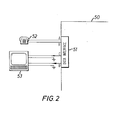
- the arrangement is shown schematically in Figure 2 where the exchange is shown at 50.
- a data interface circuit is shown at 51 and has connections to a telephone instrument 52 and a data terminal device 53.
- the telephone instrument 52 is connected to the data interface by A and B wires
- the terminal device 53 is connected to the interface 51 by C and D wires.
- the C wire is a transmit wire whilst the D wire is a receive wire.
- the interface 51 operates to substitute bits representative of the data in the two least significant bit positions of each speech sample produced by an encoder in the interface circuit 51.
- the interface circuit 51 operates to extract the data bits from the speech bits, the data bits being transmitted to the device 53 and the speech bits being fed to a decoder for transmission as analogue signals to the telephone instrument 52. Switching of the samples by the digital switching device takes place as described in U.K. Patent Specification No. 2 027 565.
- FIG 3 is a more detailed diagram of the interface circuit 51 which is designed to operate with a valid data code of a binary 1 followed by 0000000.
- the A and B wires associated with the telephone instrument are connected by a two wire to four wire converter 60 to a codec 61.
- the codec has an output 62 which is connected to a bit 8 insert circuit 63.
- the output 62 is also connected to a further circuit 64 which is arranged to receive the eighth bit of a speech sample transmitted from the codec 61.
- the circuit 64 is connected to a counter 65 the output from which is connected to a further circuit 66 which is arranged to sense when the count of the counter 65 reaches a count of six.
- the circuit 66 is connected to the bit 8 insert circuit 63.
- the output from the circuit 63 is connected to a bit 7 insert circuit 68 which is in turn connected to a further bit 8 insert circuit 69.
- the output of the circuit 69 is connected to the shelf multiplex circuit 11 shown in Figure 1.
- the circuits 63, 68 and 69 can be implemented using NAND gates.
- the C wire from the terminal 53 is connected to an input of Universal Asynchronous receive/transmit device (UART) 70 which has outputs 71 connected to a shift register 72.
- the output from the shift register 72 is connected to a second input of the circuit 68.
- a further output from the UART 73 is connected to the circuits 68, 69 by lines 74, 75.
- the UART also receives signals from the shelf multiplex 11 via line 78 which is also connected directly to the codec 61.
- the line 78 is connected by a circuit 79 to a shift register 80.
- the shift register 80 has parallel outputs 81 which connect to the UART 70.
- the UART 70 has an output which is connected to the D wire of Figure 2.
- the line 78 is also connected to the UART via a circuit 84 which receives the eighth bit of incoming samples, a counter 85 and a circuit 86.
- characters are transmitted serially from the terminal device 53 using standard V24 signal levels and are received at the interface circuit 51 by a buffer which converts the signals to TTL levels.
- the signals are fed to the UART 70 which recognises the start bit of the code and staticises the data as an eight bit word.
- a complete word has been received in the UART it is transmitted through the exchange by inserting it one bit at a time into the bit 7 position of eight successive words from the PCM encoder 61. This is carried out using the shift register 72 and the circuit 68.
- a code is inserted into the bit 8 position of the same words by the circuit 69 to indicate that the data is being sent.
- the valid data code is chosen to be a binary 1 followed by 0000000.
- This code which is shown in Table 1, identifies the start of the data and is simple to implement.
- Table 1 shows serial signals transmitted through the exchange of Figure 1. The first four lines show a normal frame containing speech only and the next four lines show a frame containing data and code bits in the P7 and P8 positions.
- the circuit consisting of components 64, 65 and 66 is provided to monitor the bit 8 signal leaving the codec 61 and operates as follows. A "1" in the bit 8 position causes the counter 65 to be reset and a "0" causes it to be-incremented. If the count reaches 6 as sensed by the circuit 66 a "0" in the next bit 8 position would complete the code. This bit is therefore forced to a "1" avoiding the code and the counter 65 is reset.
- the data in each speech sample passes through the exchange along with speech bits in the normal way as described in the above mentioned Patent Specification and then arrives at the receive side of a data port.
- All bit 7 information in the incoming stream passes through the shift register 80 whilst the bit 8 code is monitored by the counter 85 which is similar to the counter 65 on the transmit side.
- the counter 85 is reset by a "1" and incremented by a "0". If the count ever reaches the value 7 as sensed by the circuit 86 it indicates that the data has been transmitted from the far end and at this instant the shift register 80 will contain a complete data word.
- This data is loaded into the UART 70 and sent serially via a line driver and receive data line to the terminal device 53.
- the protocol within the exchange allows transmission of up to 1000 8 bit characters per sec.
- the system can therefore be used with devices of up to 9600 baud since this corresponds to 960 characters per sec after start and stop bits have been removed.
- the clock signal to the UART on the data interface will be set to match the speed of the terminal device connected to that particular port. This will allow devices of different speeds to communicate via the exchange. Slow devices will always be able to send to faster ones and faster devices will be able to send to slower ones if pauses are left between the characters to reduce the mean data rate.
- An advantage of the present approach is that a combined speech and signalling port can be provided very simply with no requirement for special operating software within the digital switching exchange.
- the telephone associated with the data port is used quite normally for making and receiving calls with speech only so that all facilities associated with the stored program exchange e.g. diversion, transfer, are available. If a call is made to another port which is equipped for data, voice communication can continue whilst data is being sent via the data channel.
Abstract
Description
- This invention relates to the transmission of data in the digital speech paths of a digital transmission arrangement.
- Telephone exchanges are known in which a digital switching device can interconnect a plurality of ports associated with the exchange. The switching device operates on digitally encoded speech samples with each sample comprising a plurality of bits, typically 8. Digital switching devices are also used to switch digital signals representative of data between data terminal devices such as VDU's and teletypes.
- It has been proposed in, for example, European Patent Application No. 0006244 to transmit data with digitally encoded speech samples by replacing one or more of the least significant bits of each speech sample by a data bit or bits. A problem in such an arrangement is that of providing an effective means of indicating when valid data is present in speech samples.
- The present invention is concerned with a method and apparatus which provide a relatively simple and effective way of indicating when data is present in speech samples.
- According to a first aspect of the present invention there is provided a method of transmitting data with digitally encoded speech samples in a digital transmission system in which one or more of the least significant bits of a speech sample is replaced by a bit or bits representative of data to be transmitted characterised in that at least two of the least significant bits are replaced, one of the replaced-bits being a control bit and another a data bit.
- According to a second aspect of the present invention there is provided a method of transmitting data through a telephone exchange which is arranged to switch digitally encoded speech samples characterised in that at least two of the least significant bits of each sample are replaced so that one of the replaced bits is a control bit and another a data bit.
- The control bits may be arranged to define a valid data code of
binary 1 followed by 0000000. - At a receiving port the speech bits are separated from the data bits so that the data bits can be transmitted to a data terminal and the speech bits decoded prior to transmission to a telephone instrument.
- According to a third aspect of the present invention there is provided a digital transmission arrangement for transmitting digitally encoded speech samples between two or more terminals in which data is transmitted with the speech samples by replacing one or more of the least significant bits of each speech sample by a bit or bits representative of the data characterised in that each terminal has associated therewith circuit means for replacing at least the two least significant bits of each speech sample so that one of the replaced bits is a control bit and another bit is a data bit.
- Each terminal may include a circuit which, when data is not inserted in the speech samples, operates to prevent that bit of each speech sample corresponding to the control bit from being in a condition indicative of data being present. Each said circuit may include a counter which is arranged to be incremented when the least significant bit of each speech sample has a predetermined binary value and means for sensing when the count of the counter reaches a predetermined value. Each terminal may include means for detecting bits representative of data in speech samples received by the terminal.
- According to a fourth aspect of the present invention there is provided an interface circuit for a telephone exchange which is arranged to switch digitally encoded speech samples, said interface circuit being characterised in that it comprises a first input/output terminal for connection to a telephone instrument, coding and decoding means connected to said first input/ output terminal for coding and decoding speech signals, said coding and decoding means having an output from which digitally encoded speech samples can be transmitted to a digital switching device of the telephone exchange and an input for receiving digitally encoded speech samples from the switching device, a second input/output terminal for connection to a data terminal device, and bit insertion means coupling the said second input/output terminal to the output of the coding and decoding means and arranged to replace at least the two least significant bits of a speech sample so that one bit is a control bit and another a data bit.
- The invention will be described now by way of example only with particular reference to the accompanying drawings. In the drawings:
- Figure 1 is a block schematic diagram of a digital switching device as described in U.K. Patent Specification No. 2 027 565;
- Figure 2 is a block diagram illustrating one form of apparatus in accordance with the present invention, and
- Figure 3 is a block schematic diagram showing in more detail the apparatus of Figure 2.
- The present embodiment will be described with reference to a digital switching device of the type described in U.K. Patent Specification No. 2 027 565. This switching system is a private'automatic branch exchange (PABX) of the stored program type which uses an eight bit microprocessor as a central processing unit. Switching between lines, trunks, auxiliary units and an operator console is via pulse code modulation (PCri) techniques. Speech signals are encoded to an A-law representation prior to their transmission to the switch. Switching between parties is accomplished by sending the encoded signals at an appropriate time to a receiving party and reconverting the digital signals to analogue form. Because all the speech signals are digitally encoded before being applied to the digital switch the PABX can send the speech signals directly to a local exchange over a regenerated line system without the need for expensive PCM multiplexing equipment at the PABX location. The device has a capacity of 160 ports which typically can comprise 120 telephonic extensions, 24 exchange lines and 16 miscellaneous auxiliaries such as an MF4 detector, inter-PABX or test port circuit and an operator console interface.
- Referring to Figure 1 the PABX has a plurality of line units one of which is indicated at 10. Each line unit is associated with, for example, a telephonic termination or an exchange line and is arranged to operate synchronously to produce eight bit PCM samples every 125 usec. Each line unit includes a codec for conversion between digital and analogue signals. The line units are connected in groups of 32 to shelf multiplex circuits one of which is indicated at 11. Each line unit is connected to its associated shelf multiplex circuit via two lines, one for signals travelling in one direction and the other for signals for travelling in the opposite direction. Each
shelf multiplex circuit 11 is connected to asignalling input circuit 12, asignalling output circuit 14, aninput time switch 15 and anoutput time switch 16. The input and output time switches are connected via acabinet interface circuit 17. - The PABX also has a
tone generator circuit 19, a conference unit 20 and aspare card position 18 each of which is linked byhighways 22 to thesignalling circuits - The PABX is controlled by a
central processor unit 25 which has associatedmemories processor unit 25 and thememories address buses address decode circuit 33 and data andaddress buses - Briefly in operation during each 125 usec interval the
line unit 10 sends to its associatedshelf multiplex 11 over an individual wire a group of nine bits, eight of which comprise a speech sample and the ninth of which is part of an eight bit signalling code. The data rate between theline unit 10 and itsshelf multiplex circuit 11 is 72 kbits per sec of combined speech and signalling. Theshelf multiplex circuit 11 assembles 32 of the 72 kbits per sec stream in a fixed order onto a digital highway at 2304 kbits per sec and then separates the speech and signalling data for transmission respectively to theinput time switch 15 at 2048 kbits per sec and to thesignalling input circuit 12 at 256 kbits per sec. The time switches operate under the control of thecentral processor unit 25 to direct the digital signals to the appropriate ports. The operation of the switches is described in more detail in U.K. Patent Specification No. 2 027 565 and will not be described here. - In the present arrangement each
interface circuit 10 is arranged so that simultaneous transmission of speech and data signals can take place between ports of the exchange. The proposal is to replace the two least significant bits of each speech sample from an encoder with bits representing the data to be sent and then to recover that data at a receiving port prior to the decoder associated with that port. The arrangement is shown schematically in Figure 2 where the exchange is shown at 50. A data interface circuit is shown at 51 and has connections to atelephone instrument 52 and adata terminal device 53. Thetelephone instrument 52 is connected to the data interface by A and B wires, and theterminal device 53 is connected to theinterface 51 by C and D wires. The C wire is a transmit wire whilst the D wire is a receive wire. If data is to be transmitted from thedevice 53 to another port associated with the exchange, theinterface 51 operates to substitute bits representative of the data in the two least significant bit positions of each speech sample produced by an encoder in theinterface circuit 51. When data is being received from another port theinterface circuit 51 operates to extract the data bits from the speech bits, the data bits being transmitted to thedevice 53 and the speech bits being fed to a decoder for transmission as analogue signals to thetelephone instrument 52. Switching of the samples by the digital switching device takes place as described in U.K. Patent Specification No. 2 027 565. - It will be appreciated that this operation only occurs when there is data available to transmit. Otherwise each speech sample uses all available eight bits. The result of the substitution process is a small increase in the quantising noise heard in the speech channel when data is being sent but as only the two least significant bits of the code word are involved the effect is very slight. When no data is being sent the degradation of the speech channel is negligible.
- Figure 3 is a more detailed diagram of the
interface circuit 51 which is designed to operate with a valid data code of abinary 1 followed by 0000000. As shown in this Figure the A and B wires associated with the telephone instrument are connected by a two wire to four wire converter 60 to acodec 61. The codec has anoutput 62 which is connected to abit 8insert circuit 63. Theoutput 62 is also connected to afurther circuit 64 which is arranged to receive the eighth bit of a speech sample transmitted from thecodec 61. Thecircuit 64 is connected to acounter 65 the output from which is connected to afurther circuit 66 which is arranged to sense when the count of thecounter 65 reaches a count of six. Thecircuit 66 is connected to thebit 8insert circuit 63. The output from thecircuit 63 is connected to abit 7insert circuit 68 which is in turn connected to afurther bit 8insert circuit 69. The output of thecircuit 69 is connected to theshelf multiplex circuit 11 shown in Figure 1. Thecircuits - The C wire from the terminal 53 is connected to an input of Universal Asynchronous receive/transmit device (UART) 70 which has
outputs 71 connected to ashift register 72. The output from theshift register 72 is connected to a second input of thecircuit 68. A further output from theUART 73 is connected to thecircuits lines - The UART also receives signals from the
shelf multiplex 11 vialine 78 which is also connected directly to thecodec 61. Theline 78 is connected by acircuit 79 to ashift register 80. Theshift register 80 hasparallel outputs 81 which connect to theUART 70. TheUART 70 has an output which is connected to the D wire of Figure 2. Theline 78 is also connected to the UART via acircuit 84 which receives the eighth bit of incoming samples, acounter 85 and acircuit 86. - In operation characters are transmitted serially from the
terminal device 53 using standard V24 signal levels and are received at theinterface circuit 51 by a buffer which converts the signals to TTL levels. The signals are fed to theUART 70 which recognises the start bit of the code and staticises the data as an eight bit word. When a complete word has been received in the UART it is transmitted through the exchange by inserting it one bit at a time into thebit 7 position of eight successive words from thePCM encoder 61. This is carried out using theshift register 72 and thecircuit 68. At the same time a code is inserted into thebit 8 position of the same words by thecircuit 69 to indicate that the data is being sent. The valid data code is chosen to be a binary 1 followed by 0000000. This code, which is shown in Table 1, identifies the start of the data and is simple to implement. In Table 1 SA to SH represent signalling bits, P1 to P8 speech bits with P8 being the least significant bit, DO to D7 data bits inserted in place of P7, and CO to C7 the data valid code inserted in place of P8. In this case CO=1 and C1 to C7 = 0. Table 1 shows serial signals transmitted through the exchange of Figure 1. The first four lines show a normal frame containing speech only and the next four lines show a frame containing data and code bits in the P7 and P8 positions. -

- It is important that the valid data code is never generated by the encoder itself or a receiving port will receive the spurious data character. The circuit consisting of
components bit 8 signal leaving thecodec 61 and operates as follows. A "1" in thebit 8 position causes thecounter 65 to be reset and a "0" causes it to be-incremented. If the count reaches 6 as sensed by the circuit 66 a "0" in thenext bit 8 position would complete the code. This bit is therefore forced to a "1" avoiding the code and thecounter 65 is reset. - The effect of substituting the least significant bits of each speech sample as described above on the speech performance of the system is negligible. Calculations indicate that the circuit has a probability of 0.4% of operating on each speech sample and on each occasion that this occurs the sample will only be altered by one step on a 256 point encoding code.
- The data in each speech sample passes through the exchange along with speech bits in the normal way as described in the above mentioned Patent Specification and then arrives at the receive side of a data port. All
bit 7 information in the incoming stream passes through theshift register 80 whilst thebit 8 code is monitored by thecounter 85 which is similar to thecounter 65 on the transmit side. Thecounter 85 is reset by a "1" and incremented by a "0". If the count ever reaches thevalue 7 as sensed by thecircuit 86 it indicates that the data has been transmitted from the far end and at this instant theshift register 80 will contain a complete data word. This data is loaded into theUART 70 and sent serially via a line driver and receive data line to theterminal device 53. - The protocol within the exchange allows transmission of up to 1000 8 bit characters per sec. The system can therefore be used with devices of up to 9600 baud since this corresponds to 960 characters per sec after start and stop bits have been removed. The clock signal to the UART on the data interface will be set to match the speed of the terminal device connected to that particular port. This will allow devices of different speeds to communicate via the exchange. Slow devices will always be able to send to faster ones and faster devices will be able to send to slower ones if pauses are left between the characters to reduce the mean data rate.
- An advantage of the present approach is that a combined speech and signalling port can be provided very simply with no requirement for special operating software within the digital switching exchange. The telephone associated with the data port is used quite normally for making and receiving calls with speech only so that all facilities associated with the stored program exchange e.g. diversion, transfer, are available. If a call is made to another port which is equipped for data, voice communication can continue whilst data is being sent via the data channel.
- It will be appreciated that the present technique can be used with codes other than the one described above. Also it is possible to use a different number of the least significant bits of each speech sample to provide the data channel. In theory as many as 7 bits of an 8 bit sample may be employed.
- The technique is described above in terms of a single exchange. It will, however, operate over many exchanges within a telephone network.
- Although the present invention has been described in terms of a telephone exchange it has much wider application and could be used over any digital transmission link which carries digitally encoded speech samples.
Claims (11)
Priority Applications (1)
| Application Number | Priority Date | Filing Date | Title |
|---|---|---|---|
| AT82300421T ATE13735T1 (en) | 1981-02-16 | 1982-01-27 | METHOD AND DEVICE FOR TRANSMISSION OF DATA WITH DIGITAL CODED SPEECH. |
Applications Claiming Priority (2)
| Application Number | Priority Date | Filing Date | Title |
|---|---|---|---|
| GB8104827 | 1981-02-16 | ||
| GB8104827 | 1981-02-16 |
Publications (2)
| Publication Number | Publication Date |
|---|---|
| EP0058482A1 true EP0058482A1 (en) | 1982-08-25 |
| EP0058482B1 EP0058482B1 (en) | 1985-06-05 |
Family
ID=10519742
Family Applications (1)
| Application Number | Title | Priority Date | Filing Date |
|---|---|---|---|
| EP82300421A Expired EP0058482B1 (en) | 1981-02-16 | 1982-01-27 | Method and apparatus for transmitting data with digitally encoded speech |
Country Status (4)
| Country | Link |
|---|---|
| EP (1) | EP0058482B1 (en) |
| AT (1) | ATE13735T1 (en) |
| DE (1) | DE3263964D1 (en) |
| HK (1) | HK50688A (en) |
Cited By (19)
| Publication number | Priority date | Publication date | Assignee | Title |
|---|---|---|---|---|
| EP0110360A2 (en) * | 1982-11-30 | 1984-06-13 | Alcatel N.V. | Circuit arrangement for composing and separating speech and data during the transmission in a digital switching network |
| DE3523809A1 (en) * | 1985-05-21 | 1986-11-27 | Polygram Gmbh, 2000 Hamburg | METHOD FOR TIME COMPRESSION OF INFORMATION IN DIGITAL FORM |
| WO1989008915A1 (en) * | 1988-03-18 | 1989-09-21 | Imperial College Of Science, Technology & Medicine | Digital data security system |
| EP0365071A2 (en) * | 1988-10-15 | 1990-04-25 | Philips Patentverwaltung GmbH | Method for distributing data signals over broadcast satellites |
| WO1994006237A1 (en) * | 1992-09-01 | 1994-03-17 | Chris Reilly | Integrated services digital network complementary modem |
| AU674851B2 (en) * | 1992-09-01 | 1997-01-16 | Chris Reilly | Integrated services digital network complementary modem |
| US5872531A (en) * | 1991-05-29 | 1999-02-16 | Pacific Microsonics, Inc. | Signal encode/decode system |
| WO1999060738A1 (en) * | 1998-05-21 | 1999-11-25 | Conexant Systems, Inc. | System and method for providing an enhanced audio quality telecommunication session |
| WO2000007352A1 (en) * | 1998-07-28 | 2000-02-10 | Conexant Systems, Inc. | Control channel for modem communication |
| US6208715B1 (en) | 1995-11-02 | 2001-03-27 | Nokia Telecommunications Oy | Method and apparatus for transmitting messages in a telecommunication system |
| US6301369B2 (en) | 1992-07-31 | 2001-10-09 | Digimarc Corporation | Image marking to permit later identification |
| US6317505B1 (en) | 1992-07-31 | 2001-11-13 | Digimarc Corporation | Image marking with error correction |
| US6343138B1 (en) | 1993-11-18 | 2002-01-29 | Digimarc Corporation | Security documents with hidden digital data |
| US6430302B2 (en) | 1993-11-18 | 2002-08-06 | Digimarc Corporation | Steganographically encoding a first image in accordance with a second image |
| US6542620B1 (en) | 1993-11-18 | 2003-04-01 | Digimarc Corporation | Signal processing to hide plural-bit information in image, video, and audio data |
| US6560349B1 (en) * | 1994-10-21 | 2003-05-06 | Digimarc Corporation | Audio monitoring using steganographic information |
| US6757406B2 (en) | 1993-11-18 | 2004-06-29 | Digimarc Corporation | Steganographic image processing |
| US6792542B1 (en) | 1998-05-12 | 2004-09-14 | Verance Corporation | Digital system for embedding a pseudo-randomly modulated auxiliary data sequence in digital samples |
| US7980596B2 (en) | 2001-12-24 | 2011-07-19 | L-1 Secure Credentialing, Inc. | Increasing thermal conductivity of host polymer used with laser engraving methods and compositions |
Families Citing this family (3)
| Publication number | Priority date | Publication date | Assignee | Title |
|---|---|---|---|---|
| US6381341B1 (en) | 1996-05-16 | 2002-04-30 | Digimarc Corporation | Watermark encoding method exploiting biases inherent in original signal |
| US6674876B1 (en) | 2000-09-14 | 2004-01-06 | Digimarc Corporation | Watermarking in the time-frequency domain |
| ATE491190T1 (en) | 2003-04-16 | 2010-12-15 | L 1 Secure Credentialing Inc | THREE-DIMENSIONAL DATA STORAGE |
Citations (3)
| Publication number | Priority date | Publication date | Assignee | Title |
|---|---|---|---|---|
| GB1555394A (en) * | 1978-04-04 | 1979-11-07 | Standard Telephones Cables Ltd | Digital signalling especially in an automatic telecommunication system |
| EP0006244A1 (en) * | 1978-06-20 | 1980-01-09 | Siemens Aktiengesellschaft | Telecommunication system |
| GB2063018A (en) * | 1979-10-08 | 1981-05-28 | Gen Electric Co Ltd | Telecommunication system |
Family Cites Families (1)
| Publication number | Priority date | Publication date | Assignee | Title |
|---|---|---|---|---|
| SE404982B (en) * | 1977-12-22 | 1978-11-06 | Ericsson Telefon Ab L M | METHOD AND DEVICE FOR TRANSMITTING DIGITAL INFORMATION IN A TELEPHONE SYSTEM |
-
1982
- 1982-01-27 DE DE8282300421T patent/DE3263964D1/en not_active Expired
- 1982-01-27 EP EP82300421A patent/EP0058482B1/en not_active Expired
- 1982-01-27 AT AT82300421T patent/ATE13735T1/en not_active IP Right Cessation
-
1988
- 1988-07-07 HK HK506/88A patent/HK50688A/en not_active IP Right Cessation
Patent Citations (3)
| Publication number | Priority date | Publication date | Assignee | Title |
|---|---|---|---|---|
| GB1555394A (en) * | 1978-04-04 | 1979-11-07 | Standard Telephones Cables Ltd | Digital signalling especially in an automatic telecommunication system |
| EP0006244A1 (en) * | 1978-06-20 | 1980-01-09 | Siemens Aktiengesellschaft | Telecommunication system |
| GB2063018A (en) * | 1979-10-08 | 1981-05-28 | Gen Electric Co Ltd | Telecommunication system |
Non-Patent Citations (1)
| Title |
|---|
| International Conference on Communications, June 10-14, 1979 Boston New York (US) A.G. ORBELL "Preparations for Evolution Towards an Integrated Services Digital Network", pages 29.1.1-29.1.6 * page 29.1.3, left-hand column, 2nd paragraph * * |
Cited By (36)
| Publication number | Priority date | Publication date | Assignee | Title |
|---|---|---|---|---|
| EP0110360A3 (en) * | 1982-11-30 | 1987-11-25 | Alcatel N.V. | Circuit arrangement for composing and separating speech and data during the transmission in a digital switching network |
| EP0110360A2 (en) * | 1982-11-30 | 1984-06-13 | Alcatel N.V. | Circuit arrangement for composing and separating speech and data during the transmission in a digital switching network |
| DE3523809A1 (en) * | 1985-05-21 | 1986-11-27 | Polygram Gmbh, 2000 Hamburg | METHOD FOR TIME COMPRESSION OF INFORMATION IN DIGITAL FORM |
| EP0205200A1 (en) * | 1985-05-21 | 1986-12-17 | POLYGRAM GmbH | Method for transmitting audio and additional information in digital form |
| WO1989008915A1 (en) * | 1988-03-18 | 1989-09-21 | Imperial College Of Science, Technology & Medicine | Digital data security system |
| EP0365071A2 (en) * | 1988-10-15 | 1990-04-25 | Philips Patentverwaltung GmbH | Method for distributing data signals over broadcast satellites |
| EP0365071A3 (en) * | 1988-10-15 | 1991-10-02 | Philips Patentverwaltung GmbH | Method for distributing data signals over broadcast satellites |
| US5872531A (en) * | 1991-05-29 | 1999-02-16 | Pacific Microsonics, Inc. | Signal encode/decode system |
| US6301369B2 (en) | 1992-07-31 | 2001-10-09 | Digimarc Corporation | Image marking to permit later identification |
| US6317505B1 (en) | 1992-07-31 | 2001-11-13 | Digimarc Corporation | Image marking with error correction |
| WO1994006237A1 (en) * | 1992-09-01 | 1994-03-17 | Chris Reilly | Integrated services digital network complementary modem |
| AU674851B2 (en) * | 1992-09-01 | 1997-01-16 | Chris Reilly | Integrated services digital network complementary modem |
| US6400827B1 (en) | 1993-11-18 | 2002-06-04 | Digimarc Corporation | Methods for hiding in-band digital data in images and video |
| US6654480B2 (en) | 1993-11-18 | 2003-11-25 | Digimarc Corporation | Audio appliance and monitoring device responsive to watermark data |
| US7536555B2 (en) | 1993-11-18 | 2009-05-19 | Digimarc Corporation | Methods for audio watermarking and decoding |
| US6343138B1 (en) | 1993-11-18 | 2002-01-29 | Digimarc Corporation | Security documents with hidden digital data |
| US7181022B2 (en) * | 1993-11-18 | 2007-02-20 | Digimarc Corporation | Audio watermarking to convey auxiliary information, and media embodying same |
| US6363159B1 (en) | 1993-11-18 | 2002-03-26 | Digimarc Corporation | Consumer audio appliance responsive to watermark data |
| US6757406B2 (en) | 1993-11-18 | 2004-06-29 | Digimarc Corporation | Steganographic image processing |
| US6404898B1 (en) | 1993-11-18 | 2002-06-11 | Digimarc Corporation | Method and system for encoding image and audio content |
| US6430302B2 (en) | 1993-11-18 | 2002-08-06 | Digimarc Corporation | Steganographically encoding a first image in accordance with a second image |
| US6496591B1 (en) | 1993-11-18 | 2002-12-17 | Digimarc Corporation | Video copy-control with plural embedded signals |
| US6539095B1 (en) * | 1993-11-18 | 2003-03-25 | Geoffrey B. Rhoads | Audio watermarking to convey auxiliary control information, and media embodying same |
| US6542620B1 (en) | 1993-11-18 | 2003-04-01 | Digimarc Corporation | Signal processing to hide plural-bit information in image, video, and audio data |
| US6675146B2 (en) | 1993-11-18 | 2004-01-06 | Digimarc Corporation | Audio steganography |
| US6567535B2 (en) * | 1993-11-18 | 2003-05-20 | Digimarc Corporation | Steganographic system with changing operations |
| US6567780B2 (en) | 1993-11-18 | 2003-05-20 | Digimarc Corporation | Audio with hidden in-band digital data |
| US6587821B1 (en) * | 1993-11-18 | 2003-07-01 | Digimarc Corp | Methods for decoding watermark data from audio, and controlling audio devices in accordance therewith |
| US6560349B1 (en) * | 1994-10-21 | 2003-05-06 | Digimarc Corporation | Audio monitoring using steganographic information |
| US6208715B1 (en) | 1995-11-02 | 2001-03-27 | Nokia Telecommunications Oy | Method and apparatus for transmitting messages in a telecommunication system |
| US6792542B1 (en) | 1998-05-12 | 2004-09-14 | Verance Corporation | Digital system for embedding a pseudo-randomly modulated auxiliary data sequence in digital samples |
| US7460667B2 (en) | 1998-05-12 | 2008-12-02 | Verance Corporation | Digital hidden data transport (DHDT) |
| WO1999060738A1 (en) * | 1998-05-21 | 1999-11-25 | Conexant Systems, Inc. | System and method for providing an enhanced audio quality telecommunication session |
| US6353666B1 (en) | 1998-05-21 | 2002-03-05 | Conexant Systems, Inc. | System and method for providing an enhanced audio quality telecommunication session |
| WO2000007352A1 (en) * | 1998-07-28 | 2000-02-10 | Conexant Systems, Inc. | Control channel for modem communication |
| US7980596B2 (en) | 2001-12-24 | 2011-07-19 | L-1 Secure Credentialing, Inc. | Increasing thermal conductivity of host polymer used with laser engraving methods and compositions |
Also Published As
| Publication number | Publication date |
|---|---|
| ATE13735T1 (en) | 1985-06-15 |
| EP0058482B1 (en) | 1985-06-05 |
| DE3263964D1 (en) | 1985-07-11 |
| HK50688A (en) | 1988-07-15 |
Similar Documents
| Publication | Publication Date | Title |
|---|---|---|
| EP0058482B1 (en) | Method and apparatus for transmitting data with digitally encoded speech | |
| US4445213A (en) | Communication line interface for controlling data information having differing transmission characteristics | |
| US4476559A (en) | Simultaneous transmission of voice and data signals over a digital channel | |
| US4403322A (en) | Voice signal converting device | |
| US4413337A (en) | Time division switching system for circuit mode and packet mode lines | |
| CA1169974A (en) | Communication system for connecting a plurality of asynchronous data processing terminals | |
| US4383316A (en) | Apparatus for and method of collating partitioned time disordered synchronous data streams | |
| US3862373A (en) | Adaptive sampling rate time division multiplexer and method | |
| US4244046A (en) | Digital data transmission system providing multipoint communications | |
| US5379293A (en) | Voice packet assembling/disassembling apparatus | |
| EP0158673B1 (en) | Plural communication channel protocol support systems | |
| US3549814A (en) | Pulse code modulation multiplex signaling system | |
| KR920003264B1 (en) | Parity checking arrangement | |
| EP0648396B1 (en) | A method of distinguishing in serial digital bit streams between at least two types of time slots in a bit stream receiver | |
| US4839888A (en) | Digital time-division multiplex switch-based telephone subscriber connection system | |
| US4644525A (en) | Line transmission systems | |
| GB1569284A (en) | Data packet switching system | |
| GB2027565A (en) | Improvements in or relating to the switching of digital signals | |
| CA1093195A (en) | Digital switching of electronic signals | |
| IL104106A (en) | Method of transmission of tele-communication signals | |
| US4723274A (en) | Arrangement for transferring data to an attendant console | |
| GB1560205A (en) | Signal transfer system for the division switching centres | |
| US4706279A (en) | Arrangement for initializing a CENTREX console interface circuit | |
| GB2053621A (en) | Digital Communication Bus System | |
| CA1141002A (en) | Communication line interface for controlling data information having differing transmission characteristics |
Legal Events
| Date | Code | Title | Description |
|---|---|---|---|
| PUAI | Public reference made under article 153(3) epc to a published international application that has entered the european phase |
Free format text: ORIGINAL CODE: 0009012 |
|
| AK | Designated contracting states |
Designated state(s): AT BE CH DE FR GB IT LU NL SE |
|
| 17P | Request for examination filed |
Effective date: 19820729 |
|
| ITF | It: translation for a ep patent filed |
Owner name: JACOBACCI & PERANI S.P.A. |
|
| GRAA | (expected) grant |
Free format text: ORIGINAL CODE: 0009210 |
|
| AK | Designated contracting states |
Designated state(s): AT BE CH DE FR GB IT LI LU NL SE |
|
| REF | Corresponds to: |
Ref document number: 13735 Country of ref document: AT Date of ref document: 19850615 Kind code of ref document: T |
|
| REF | Corresponds to: |
Ref document number: 3263964 Country of ref document: DE Date of ref document: 19850711 |
|
| ET | Fr: translation filed | ||
| PG25 | Lapsed in a contracting state [announced via postgrant information from national office to epo] |
Ref country code: LU Free format text: LAPSE BECAUSE OF NON-PAYMENT OF DUE FEES Effective date: 19860131 |
|
| PLBE | No opposition filed within time limit |
Free format text: ORIGINAL CODE: 0009261 |
|
| STAA | Information on the status of an ep patent application or granted ep patent |
Free format text: STATUS: NO OPPOSITION FILED WITHIN TIME LIMIT |
|
| 26N | No opposition filed | ||
| PGFP | Annual fee paid to national office [announced via postgrant information from national office to epo] |
Ref country code: AT Payment date: 19861216 Year of fee payment: 6 |
|
| PGFP | Annual fee paid to national office [announced via postgrant information from national office to epo] |
Ref country code: NL Payment date: 19870131 Year of fee payment: 6 |
|
| REG | Reference to a national code |
Ref country code: GB Ref legal event code: 732 |
|
| PG25 | Lapsed in a contracting state [announced via postgrant information from national office to epo] |
Ref country code: AT Effective date: 19890127 |
|
| PG25 | Lapsed in a contracting state [announced via postgrant information from national office to epo] |
Ref country code: SE Effective date: 19890128 |
|
| PG25 | Lapsed in a contracting state [announced via postgrant information from national office to epo] |
Ref country code: LI Effective date: 19890131 Ref country code: CH Effective date: 19890131 Ref country code: BE Effective date: 19890131 |
|
| BERE | Be: lapsed |
Owner name: BRITISH TELECOMMUNICATIONS P.L.C. Effective date: 19890131 |
|
| REG | Reference to a national code |
Ref country code: CH Ref legal event code: PUE Owner name: BRITISH TELECOMMUNICATIONS PUBLIC LIMITED COMPANY |
|
| PG25 | Lapsed in a contracting state [announced via postgrant information from national office to epo] |
Ref country code: NL Effective date: 19890801 |
|
| NLV4 | Nl: lapsed or anulled due to non-payment of the annual fee | ||
| PG25 | Lapsed in a contracting state [announced via postgrant information from national office to epo] |
Ref country code: FR Free format text: LAPSE BECAUSE OF NON-PAYMENT OF DUE FEES Effective date: 19890929 |
|
| REG | Reference to a national code |
Ref country code: CH Ref legal event code: PL |
|
| PG25 | Lapsed in a contracting state [announced via postgrant information from national office to epo] |
Ref country code: DE Effective date: 19891003 |
|
| REG | Reference to a national code |
Ref country code: FR Ref legal event code: ST |
|
| EUG | Se: european patent has lapsed |
Ref document number: 82300421.3 Effective date: 19891205 |
|
| PGFP | Annual fee paid to national office [announced via postgrant information from national office to epo] |
Ref country code: GB Payment date: 19971218 Year of fee payment: 17 |
|
| PG25 | Lapsed in a contracting state [announced via postgrant information from national office to epo] |
Ref country code: GB Free format text: LAPSE BECAUSE OF NON-PAYMENT OF DUE FEES Effective date: 19990127 |
|
| GBPC | Gb: european patent ceased through non-payment of renewal fee |
Effective date: 19990127 |