EP0062956A1 - Supporting device - Google Patents
Supporting device Download PDFInfo
- Publication number
- EP0062956A1 EP0062956A1 EP82200432A EP82200432A EP0062956A1 EP 0062956 A1 EP0062956 A1 EP 0062956A1 EP 82200432 A EP82200432 A EP 82200432A EP 82200432 A EP82200432 A EP 82200432A EP 0062956 A1 EP0062956 A1 EP 0062956A1
- Authority
- EP
- European Patent Office
- Prior art keywords
- parts
- supporting member
- spring
- another
- fixed
- Prior art date
- Legal status (The legal status is an assumption and is not a legal conclusion. Google has not performed a legal analysis and makes no representation as to the accuracy of the status listed.)
- Granted
Links
Images
Classifications
-
- F—MECHANICAL ENGINEERING; LIGHTING; HEATING; WEAPONS; BLASTING
- F21—LIGHTING
- F21V—FUNCTIONAL FEATURES OR DETAILS OF LIGHTING DEVICES OR SYSTEMS THEREOF; STRUCTURAL COMBINATIONS OF LIGHTING DEVICES WITH OTHER ARTICLES, NOT OTHERWISE PROVIDED FOR
- F21V21/00—Supporting, suspending, or attaching arrangements for lighting devices; Hand grips
- F21V21/14—Adjustable mountings
- F21V21/32—Flexible tubes
-
- F—MECHANICAL ENGINEERING; LIGHTING; HEATING; WEAPONS; BLASTING
- F16—ENGINEERING ELEMENTS AND UNITS; GENERAL MEASURES FOR PRODUCING AND MAINTAINING EFFECTIVE FUNCTIONING OF MACHINES OR INSTALLATIONS; THERMAL INSULATION IN GENERAL
- F16M—FRAMES, CASINGS OR BEDS OF ENGINES, MACHINES OR APPARATUS, NOT SPECIFIC TO ENGINES, MACHINES OR APPARATUS PROVIDED FOR ELSEWHERE; STANDS; SUPPORTS
- F16M11/00—Stands or trestles as supports for apparatus or articles placed thereon Stands for scientific apparatus such as gravitational force meters
- F16M11/02—Heads
- F16M11/04—Means for attachment of apparatus; Means allowing adjustment of the apparatus relatively to the stand
- F16M11/06—Means for attachment of apparatus; Means allowing adjustment of the apparatus relatively to the stand allowing pivoting
- F16M11/10—Means for attachment of apparatus; Means allowing adjustment of the apparatus relatively to the stand allowing pivoting around a horizontal axis
-
- F—MECHANICAL ENGINEERING; LIGHTING; HEATING; WEAPONS; BLASTING
- F16—ENGINEERING ELEMENTS AND UNITS; GENERAL MEASURES FOR PRODUCING AND MAINTAINING EFFECTIVE FUNCTIONING OF MACHINES OR INSTALLATIONS; THERMAL INSULATION IN GENERAL
- F16M—FRAMES, CASINGS OR BEDS OF ENGINES, MACHINES OR APPARATUS, NOT SPECIFIC TO ENGINES, MACHINES OR APPARATUS PROVIDED FOR ELSEWHERE; STANDS; SUPPORTS
- F16M11/00—Stands or trestles as supports for apparatus or articles placed thereon Stands for scientific apparatus such as gravitational force meters
- F16M11/20—Undercarriages with or without wheels
- F16M11/2007—Undercarriages with or without wheels comprising means allowing pivoting adjustment
- F16M11/2014—Undercarriages with or without wheels comprising means allowing pivoting adjustment around a vertical axis
Definitions
- the invention relates to a supporting device comprising at least two relatively rotatable parts.
- the invention has for its object to provide a supporting device of the kind set forth, in which the two parts can be readily turned with respect to one another and can maintain a fixed position relative to one another without the use of locking members.
- this can be achieved by arranging in the two parts a biassed, helically wound tensile spring fixed at least at two points.
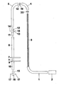
- the supporting construction comprises a tubular part 1 having a straight portion and a quarter bend.
- a member to be supported for example, a lamp holder 2.
- the supporting device furthermore comprises a tubular part 4 formed by a quarter bend and a tubular part 5 having a straight portion and an adjoined quarter bend.
- the supporting device is furthermore provided with a straight, tubular part 6, to the lower end of which is secured a supporting plate 7.
- a tubing 8 associated with the supporting member and to the lower end of the tubing 8 is fastened a supporting plate 9.
- Beneath the supporting plate 9 is fastened a tubing 10 so that-the centre line of this tubing 10 coincides with the centre line of the tubing 8.
- the lower end of the tubing 5 can be coupled with the tubing 6 with the aid of a tie piece 11 formed by a tubing 12 provided between its ends with a thickened, annular portion 13.
- This annular portion 13 has two tapped holes for receiving guard screws 14.
- a coupling piece 15 which is provided at its lower end with a thickened, annular portion 16 also having two tapped holes for receiving guard screws 17.
- a coupling piece 18 having nears its middle a thickened, annular portion 19 so that the ends of said coupling piece can be inserted into the ends of the tubings 5 and 4, the annular portion thus being locked between the ends of the tubings 4 and 5.
- a similar coupling piece 20 is used for the disposition on the ends of the tubings 1 and 4 to be joined to one another.
- the coupling piece 20 When uounting the supporting member described above first the coupling piece 20 is slipped onto the spring, then the tubing 4, the coupling 5piece 18, the tubing 5 and the coupling piece 11 in a manner such that the various parts of the supporting member, through which the spring 3 is slid, are rigidly joined to one another. Subsequently the sping 3 is firmly stretched and then fixed in the coupling piece 11 with the aid of the guard screws 14. It will be obvious that the various parts 1, 20, 4, 18, 5 and 11 are firmly drawn to one another by the spring.
- the remaining part of the spring is passed through the parts 6, 8 and 10 of the supporting member, said remaining part of the spring being also biassed and finally fixed to the coupling piece 15 with the aid of the guard screws 17.
- the supporting plate 9 tends to move towards the supporting plate 7 by the action of the spring tension produced in the portion of the tensile spring located between the guard screws 14 and the guard screws 17.
- the arrangement may be such that during mounting and generating the tensile force in the last-mentioned portion of the tensile spring 3 the plates 7 and 9 come into contact with one another, whereas an alternative resides in that with the aid of stop members (not shown) it can be ensured that the supporting plates 7 and 9 are spaced apart by a minimum distance.
- a plurality of registering springs may, as an alternative,be employed.
Abstract
Description
- The invention relates to a supporting device comprising at least two relatively rotatable parts.
- The invention has for its object to provide a supporting device of the kind set forth, in which the two parts can be readily turned with respect to one another and can maintain a fixed position relative to one another without the use of locking members.
- According to the invention this can be achieved by arranging in the two parts a biassed, helically wound tensile spring fixed at least at two points.
- By using this construction a simple structure of the supporting device can be obtained, in which the relatively rotatable parts will remain in a desired position by the friction forces produced between said parts and/or by the torsional force produced in the helical spring.
- The invention will now be described more fully with reference to the accompanying sketch showing some component parts of an embodiment of a supporting constructing at a distance from one another.
- In the embodiment shown the supporting construction comprises a
tubular part 1 having a straight portion and a quarter bend. To the righthand end of said tubular part can be fastened a member to be supported, for example, alamp holder 2. - In the
tubular part 1 is fixed the end of a helicallywound tensile spring 3. - The supporting device furthermore comprises a
tubular part 4 formed by a quarter bend and atubular part 5 having a straight portion and an adjoined quarter bend. The supporting device is furthermore provided with a straight,tubular part 6, to the lower end of which is secured a supportingplate 7. In thetubing 6 is slidable in its direction of length a tubing 8 associated with the supporting member and to the lower end of the tubing 8 is fastened a supporting plate 9. Beneath the supporting plate 9 is fastened atubing 10 so that-the centre line of thistubing 10 coincides with the centre line of the tubing 8. - The lower end of the
tubing 5 can be coupled with thetubing 6 with the aid of atie piece 11 formed by atubing 12 provided between its ends with a thickened,annular portion 13. Thisannular portion 13 has two tapped holes for receivingguard screws 14. - Into the lower end of the
tubing 10 can be inserted acoupling piece 15, which is provided at its lower end with a thickened,annular portion 16 also having two tapped holes for receiving guard screws 17.Between the ends of thetubing 4 and thetubing 5 to be joined to one another is arranged acoupling piece 18 having nears its middle a thickened,annular portion 19 so that the ends of said coupling piece can be inserted into the ends of thetubings tubings - A similar coupling piece 20 is used for the disposition on the ends of the
tubings - When uounting the supporting member described above first the coupling piece 20 is slipped onto the spring, then the
tubing 4, thecoupling 5piece 18, thetubing 5 and thecoupling piece 11 in a manner such that the various parts of the supporting member, through which thespring 3 is slid, are rigidly joined to one another. Subsequently thesping 3 is firmly stretched and then fixed in thecoupling piece 11 with the aid of theguard screws 14. It will be obvious that thevarious parts - The remaining part of the spring is passed through the
parts coupling piece 15 with the aid of theguard screws 17. It will be obvious that as a result the supporting plate 9 tends to move towards the supportingplate 7 by the action of the spring tension produced in the portion of the tensile spring located between theguard screws 14 and theguard screws 17. The arrangement may be such that during mounting and generating the tensile force in the last-mentioned portion of thetensile spring 3 theplates 7 and 9 come into contact with one another, whereas an alternative resides in that with the aid of stop members (not shown) it can be ensured that the supportingplates 7 and 9 are spaced apart by a minimum distance. - By correct choice of the dimensions of the spring and, as the case may be, by generating a given torsional stress in the spring by an initial turn of the various parts relative to one another after the spring is fastened, a sufficiently high friction force can be produced between the various adjoining parts of the supporting member and an adequate torsional force can be generated in the spring to ensure that subsequent to a turn of one or more of the
parts plates 7 and 9. - By building up the supporting member with the use of curved or sharply bent parts a great number of different positions can be set for the supported member, for example, a
lamp holder 2 or the like. - Instead of using a single spring fixed at several spots a plurality of registering springs may, as an alternative,be employed.
- The figures used in the claims are only meant to explain more clearly the intention of the invention and are not supposed to be any
restriction 5 concerning the interpretation of the invention.
Claims (4)
Priority Applications (1)
| Application Number | Priority Date | Filing Date | Title |
|---|---|---|---|
| AT82200432T ATE14342T1 (en) | 1981-04-11 | 1982-04-08 | SUPPORT DEVICE. |
Applications Claiming Priority (2)
| Application Number | Priority Date | Filing Date | Title |
|---|---|---|---|
| NL8101790 | 1981-04-11 | ||
| NL8101790A NL8101790A (en) | 1981-04-11 | 1981-04-11 | SUPPORT DEVICE. |
Publications (2)
| Publication Number | Publication Date |
|---|---|
| EP0062956A1 true EP0062956A1 (en) | 1982-10-20 |
| EP0062956B1 EP0062956B1 (en) | 1985-07-17 |
Family
ID=19837337
Family Applications (1)
| Application Number | Title | Priority Date | Filing Date |
|---|---|---|---|
| EP82200432A Expired EP0062956B1 (en) | 1981-04-11 | 1982-04-08 | Supporting device |
Country Status (4)
| Country | Link |
|---|---|
| EP (1) | EP0062956B1 (en) |
| AT (1) | ATE14342T1 (en) |
| DE (1) | DE3264748D1 (en) |
| NL (1) | NL8101790A (en) |
Citations (8)
| Publication number | Priority date | Publication date | Assignee | Title |
|---|---|---|---|---|
| BE483690A (en) * | ||||
| US2557507A (en) * | 1950-05-11 | 1951-06-19 | Jr Victor Lang | Adjustable joint structure for electric lamp supports |
| FR1105984A (en) * | 1954-06-08 | 1955-12-09 | Advanced lamp holder | |
| US3266059A (en) * | 1963-06-19 | 1966-08-16 | North American Aviation Inc | Prestressed flexible joint for mechanical arms and the like |
| DE1909716A1 (en) * | 1968-02-26 | 1969-09-25 | Oram John Anderson | Flexible stand |
| FR2184263A5 (en) * | 1972-05-12 | 1973-12-21 | Test Sa | |
| FR2363021A1 (en) * | 1976-08-27 | 1978-03-24 | Oesterr Klima Technik | MULTI-JOINT ARMS |
| DE2840314A1 (en) * | 1978-09-15 | 1980-03-27 | Robert Goedecke | Camera tripod articulated joint - comprises part spherical component against which further spring-loaded component slides |
-
1981
- 1981-04-11 NL NL8101790A patent/NL8101790A/en not_active Application Discontinuation
-
1982
- 1982-04-08 DE DE8282200432T patent/DE3264748D1/en not_active Expired
- 1982-04-08 AT AT82200432T patent/ATE14342T1/en not_active IP Right Cessation
- 1982-04-08 EP EP82200432A patent/EP0062956B1/en not_active Expired
Patent Citations (8)
| Publication number | Priority date | Publication date | Assignee | Title |
|---|---|---|---|---|
| BE483690A (en) * | ||||
| US2557507A (en) * | 1950-05-11 | 1951-06-19 | Jr Victor Lang | Adjustable joint structure for electric lamp supports |
| FR1105984A (en) * | 1954-06-08 | 1955-12-09 | Advanced lamp holder | |
| US3266059A (en) * | 1963-06-19 | 1966-08-16 | North American Aviation Inc | Prestressed flexible joint for mechanical arms and the like |
| DE1909716A1 (en) * | 1968-02-26 | 1969-09-25 | Oram John Anderson | Flexible stand |
| FR2184263A5 (en) * | 1972-05-12 | 1973-12-21 | Test Sa | |
| FR2363021A1 (en) * | 1976-08-27 | 1978-03-24 | Oesterr Klima Technik | MULTI-JOINT ARMS |
| DE2840314A1 (en) * | 1978-09-15 | 1980-03-27 | Robert Goedecke | Camera tripod articulated joint - comprises part spherical component against which further spring-loaded component slides |
Also Published As
| Publication number | Publication date |
|---|---|
| NL8101790A (en) | 1982-11-01 |
| DE3264748D1 (en) | 1985-08-22 |
| ATE14342T1 (en) | 1985-08-15 |
| EP0062956B1 (en) | 1985-07-17 |
Similar Documents
| Publication | Publication Date | Title |
|---|---|---|
| SU1153849A3 (en) | Device for securing electric cables or pipelines | |
| US4878662A (en) | Exercise machine weight guide | |
| RU2076188C1 (en) | Connecting pin | |
| DE102009011614B4 (en) | Sensor arrangement for a motor vehicle | |
| EP0850579A3 (en) | Mount for a spring device | |
| US4002953A (en) | Device for fixing a printed circuit board to a casket-like support | |
| KR900014811A (en) | Device for fastening bundle tubes of steam generators with anti-vibration bars | |
| US4452414A (en) | Supporting device | |
| RU2001101864A (en) | SUPPORT FENCING FOR CURVED CONVEYOR LINES | |
| EP0062956A1 (en) | Supporting device | |
| KR930010355A (en) | Joint connection device of vehicle exhaust line member | |
| DE68912761T2 (en) | End connection block with cable clamp device, especially for household appliances. | |
| EP0029314A1 (en) | Clamping device | |
| DE4228305A1 (en) | Mounting support for flexible water tubes or electrical cables - has tubes located in pivot mounted clips on main fixing bracket | |
| US2545416A (en) | Support for luminous tubing | |
| US5857965A (en) | Operating stage | |
| DE2413928B2 (en) | Vibration-dampening field spacer | |
| ATE69644T1 (en) | HOSE CLAMP. | |
| SU1095291A1 (en) | Apparatus for laying cable in spiral oval turns | |
| CN214870195U (en) | Suspender mounting seat | |
| FR2304048A1 (en) | Tube bundle support - has component holding innermost tube coils in notches in supporting bars | |
| US3133985A (en) | Cable spreader assembly and bracing member | |
| FR2704362B1 (en) | Electrical connector with magnetic fixing on a two-conductor rail. | |
| SU1093846A1 (en) | Variable diameter gear | |
| KR970707675A (en) | Fastening of a picture tube in a cabinet of a TV receiver set |
Legal Events
| Date | Code | Title | Description |
|---|---|---|---|
| PUAI | Public reference made under article 153(3) epc to a published international application that has entered the european phase |
Free format text: ORIGINAL CODE: 0009012 |
|
| AK | Designated contracting states |
Designated state(s): AT BE CH DE FR GB IT LU NL SE |
|
| 17P | Request for examination filed |
Effective date: 19830418 |
|
| ITF | It: translation for a ep patent filed |
Owner name: ING. ZINI MARANESI & C. S.R.L. |
|
| GRAA | (expected) grant |
Free format text: ORIGINAL CODE: 0009210 |
|
| AK | Designated contracting states |
Designated state(s): AT BE CH DE FR GB IT LI LU NL SE |
|
| PG25 | Lapsed in a contracting state [announced via postgrant information from national office to epo] |
Ref country code: LI Effective date: 19850717 Ref country code: CH Effective date: 19850717 Ref country code: AT Effective date: 19850717 |
|
| REF | Corresponds to: |
Ref document number: 14342 Country of ref document: AT Date of ref document: 19850815 Kind code of ref document: T |
|
| PG25 | Lapsed in a contracting state [announced via postgrant information from national office to epo] |
Ref country code: SE Effective date: 19850730 |
|
| REF | Corresponds to: |
Ref document number: 3264748 Country of ref document: DE Date of ref document: 19850822 |
|
| ET | Fr: translation filed | ||
| REG | Reference to a national code |
Ref country code: CH Ref legal event code: PL |
|
| PG25 | Lapsed in a contracting state [announced via postgrant information from national office to epo] |
Ref country code: LU Free format text: LAPSE BECAUSE OF NON-PAYMENT OF DUE FEES Effective date: 19860430 |
|
| PLBE | No opposition filed within time limit |
Free format text: ORIGINAL CODE: 0009261 |
|
| STAA | Information on the status of an ep patent application or granted ep patent |
Free format text: STATUS: NO OPPOSITION FILED WITHIN TIME LIMIT |
|
| 26N | No opposition filed | ||
| PGFP | Annual fee paid to national office [announced via postgrant information from national office to epo] |
Ref country code: FR Payment date: 19890428 Year of fee payment: 8 |
|
| ITTA | It: last paid annual fee | ||
| PGFP | Annual fee paid to national office [announced via postgrant information from national office to epo] |
Ref country code: NL Payment date: 19890430 Year of fee payment: 8 Ref country code: GB Payment date: 19890430 Year of fee payment: 8 |
|
| PGFP | Annual fee paid to national office [announced via postgrant information from national office to epo] |
Ref country code: BE Payment date: 19890512 Year of fee payment: 8 |
|
| PGFP | Annual fee paid to national office [announced via postgrant information from national office to epo] |
Ref country code: DE Payment date: 19890616 Year of fee payment: 8 |
|
| PG25 | Lapsed in a contracting state [announced via postgrant information from national office to epo] |
Ref country code: GB Effective date: 19900408 |
|
| PG25 | Lapsed in a contracting state [announced via postgrant information from national office to epo] |
Ref country code: BE Effective date: 19900430 |
|
| BERE | Be: lapsed |
Owner name: ANSEMS HENRICUS JOSEPHUS Effective date: 19900430 |
|
| PG25 | Lapsed in a contracting state [announced via postgrant information from national office to epo] |
Ref country code: NL Effective date: 19901101 |
|
| GBPC | Gb: european patent ceased through non-payment of renewal fee | ||
| NLV4 | Nl: lapsed or anulled due to non-payment of the annual fee | ||
| PG25 | Lapsed in a contracting state [announced via postgrant information from national office to epo] |
Ref country code: FR Effective date: 19901228 |
|
| PG25 | Lapsed in a contracting state [announced via postgrant information from national office to epo] |
Ref country code: DE Effective date: 19910101 |
|
| REG | Reference to a national code |
Ref country code: FR Ref legal event code: ST |