EP0066112A2 - Stationary optical longitudinal refractor - Google Patents
Stationary optical longitudinal refractor Download PDFInfo
- Publication number
- EP0066112A2 EP0066112A2 EP82103957A EP82103957A EP0066112A2 EP 0066112 A2 EP0066112 A2 EP 0066112A2 EP 82103957 A EP82103957 A EP 82103957A EP 82103957 A EP82103957 A EP 82103957A EP 0066112 A2 EP0066112 A2 EP 0066112A2
- Authority
- EP
- European Patent Office
- Prior art keywords
- refractor
- elements
- time
- fixed position
- rays
- Prior art date
- Legal status (The legal status is an assumption and is not a legal conclusion. Google has not performed a legal analysis and makes no representation as to the accuracy of the status listed.)
- Granted
Links
- 230000003287 optical effect Effects 0.000 title 1
- 239000012780 transparent material Substances 0.000 claims abstract description 5
- 239000012141 concentrate Substances 0.000 abstract description 3
- 239000006096 absorbing agent Substances 0.000 description 4
- 230000007246 mechanism Effects 0.000 description 4
- 238000000926 separation method Methods 0.000 description 2
- 230000005540 biological transmission Effects 0.000 description 1
- 238000010276 construction Methods 0.000 description 1
- 230000008878 coupling Effects 0.000 description 1
- 238000010168 coupling process Methods 0.000 description 1
- 238000005859 coupling reaction Methods 0.000 description 1
- 239000006185 dispersion Substances 0.000 description 1
- 239000000463 material Substances 0.000 description 1
- 239000000126 substance Substances 0.000 description 1
- 239000000758 substrate Substances 0.000 description 1
Images


Classifications
-
- F—MECHANICAL ENGINEERING; LIGHTING; HEATING; WEAPONS; BLASTING
- F24—HEATING; RANGES; VENTILATING
- F24S—SOLAR HEAT COLLECTORS; SOLAR HEAT SYSTEMS
- F24S23/00—Arrangements for concentrating solar-rays for solar heat collectors
- F24S23/30—Arrangements for concentrating solar-rays for solar heat collectors with lenses
- F24S23/31—Arrangements for concentrating solar-rays for solar heat collectors with lenses having discontinuous faces, e.g. Fresnel lenses
-
- Y—GENERAL TAGGING OF NEW TECHNOLOGICAL DEVELOPMENTS; GENERAL TAGGING OF CROSS-SECTIONAL TECHNOLOGIES SPANNING OVER SEVERAL SECTIONS OF THE IPC; TECHNICAL SUBJECTS COVERED BY FORMER USPC CROSS-REFERENCE ART COLLECTIONS [XRACs] AND DIGESTS
- Y02—TECHNOLOGIES OR APPLICATIONS FOR MITIGATION OR ADAPTATION AGAINST CLIMATE CHANGE
- Y02E—REDUCTION OF GREENHOUSE GAS [GHG] EMISSIONS, RELATED TO ENERGY GENERATION, TRANSMISSION OR DISTRIBUTION
- Y02E10/00—Energy generation through renewable energy sources
- Y02E10/40—Solar thermal energy, e.g. solar towers
Definitions
- the present invention relates to a special refractor, that is to say, a flat plate consisting of various flanked dioptric elements of transparent material with refractive index higher than 1, characterized by the fact that the elements making up the system have an afocal profile of asymmetrical geometry, whereby said refractor has the capacity, although remaining fixed with time, to concentrate the luminous rays of the solar source on to a surface of considerably smaller dimensions lying beneath the refractor.
- a special refractor that is to say, a flat plate consisting of various flanked dioptric elements of transparent material with refractive index higher than 1, characterized by the fact that the elements making up the system have an afocal profile of asymmetrical geometry, whereby said refractor has the capacity, although remaining fixed with time, to concentrate the luminous rays of the solar source on to a surface of considerably smaller dimensions lying beneath the refractor.
- This refractor represents considerable progress in its parti cular field.
- Fresnel type lenses to concentrate a beam parallel rays towards its focal point has been well known for some time now. However, such a lens performs this function if it positioned so as always to remain at right angles with time to the incoming direction of the sun's rays.
- the Fresnel lenses are mounted on so-called “tracking” or “sun follower” mechanisms which move the lens in an appropriate manner.
- a fixed refractor of the concentrating type transmits a solar image which, over a period of time, assumes such dimensions so as to drastically compromise the possibility of collecting solar energy with a fixed absorber.
- the refractor in accordance with the invention has been devised as stated above, and succeeds in accomplishing a spatial concentration of the solar energy transmitted by keeping its position unaltered with time, even without the aid of additional elements for correcting the direction of the luminous rays refracted by the refractor profile.
- this refractor succeeds, at least for a period of 6 hours, in concentrating the solar energy striking said refractor, on to an absorber of considerably smaller dimensions than the exposed surface area, with a concentration ratio equal to or greater than 2.
- concentration ratio we mean the ratio between width L of the refractor surface exposed to the sun and the corresponding dimension L governing the surface struck by the solar image during the period of time considered.
- Said profile can be advantageously used in habouring solar energy in the most suitable forms each time it is desidera- ble to avoid the complication of having sun followers or systems for correcting the direction of the refracted rays, and when it required to transfer the energy striking a surfa ce of arrestment to a collecting surface of smaller dimensions.
- the refractor in accordance with the invention consists of Fresnel type elements, either standard or modified version, said elements being made of any transparent material and arranged asymmetrically about a preselected axis as its profile does not allow an axial symmetry.
- the so-designed profile does not have any single focal point as the elements making up the refractor do not have the same focal length along the axis of separation between the upper elements and the lower elements, that is to say, by keeping the refractor position fixed, a greater concentration of the sun's rays can be accomplished.
- the central element that is the element of jointof the refractor about the preselected axis, is afocal because the half elements comprising it, are of the flat-convex lens type with different focal points.
- the central element actually consists of one single element formed by two different half lenses.
- a refractor of symmetrical profile for example a Fresnel type one
- the asymmetrical profile, to which the herein disclosed invention refers thanks to the higher dioptric power of the lower elements with respect to that of the upper elements, succeeds, while limiting the excursion of the rays refracted in downwards direction by the upper elements, in increasing the deviation of the rays refracted in the upwards direction by the lower elements.
- a considerably higher concentration ratio is obtained on the plane of maximum concentration with respect to that obtained on the plane of maximum concentration of a symmetrical refractor having the same overall dimensions as the asymmetrical refractor with which comparison is made.
- the asymmetrical refractor can, in accordance with the required exposed surface and the solar image characteristics to be obtained, consist of an arbitary number of upper and lower dioptric elements.
- the profile of the various elements can be of the standard Fresnel type or be of a modified type.
- the angle formed by the axis X of the refracted rays with the horizontal plane T is indicated by the letter ⁇ , while L designates the width of refractor R exposed to the sun.
- the common thickness.of the dioptric elements is indicated by the letters ei, while eo instead denotes the thickness of the substrate of said elements.
- the upper dioptric elements Es preferably making up the refractor in accordance with the invention are numbered from 1 to 6.
- the central dioptric element is indicated by Ec and the lower dioptric elements by Ei.
- the radius of curvature of a dioptric element is indicated by Ri while Xci and Yci indicate the co-ordinates of the central of curvature of said dioptric element.
- the letters Yi instead denote the distance of axis X from the first lower dioptric element Ei and from the first upper dioptric element Es respectively.
- the luminous rays A strike the plain or unprofiled surface of refractor R.
- the focal point of a generic dioptric element is taken to be the point of intersection of the refracted rays with axis x when the light strikes the exposed surface of the refractor at right angles.
- the plane of maximum concentration lies in a position perpendicular to that of the profile (parallel to the plate) at a distance of 325.72 mm from the origin 0 of the axis X, of separation between the upper elements and the lower elements.
- the maximum ordinate towards the top (y negative) (fig. 6) reached on the collecting plane by the sun's rays is given by the ray refracted by the outermost end Q of the 6th upper element, while the minimum ordinate towards the bottom (y positive) is determined by-the outermost end of the central element (denoted by the letter P in fig. 2).
- the ratio between width L (fig.1) of the refractor and dimension L 1 (fig. 6) within which takes place the maximum excursion of the solar image is between 2 and 2.1.
- the orientation of the profile in fig. 1 is East-West in the longitudinal direction of the lens, while the plane of tilt with respect to the horizontal plane will depend on the latitude of the locality where the lens is to be used.
- the refractors in figures 5 and 6 are consideted to be exposed perpendicularly to the sun's rays at 12.00 ' hours in the day of the summer solstice, at a latitude of 42° North.
- refractor_in accordance with the invention is not bound by the number, as several refractors can be used coupled together when deemed necessary (and as shown in fig. 7 which limits, for the sake of simplicity, the coupling of the refractors according to the invention to a total of two).
- the refractor of asymmetrical profile can be made of any transparent material and can be of any dimensions; furthermore, thanks to its special concentrating power, the refractor possesses certain considerable advantages such as:
Landscapes
- Engineering & Computer Science (AREA)
- Chemical & Material Sciences (AREA)
- Life Sciences & Earth Sciences (AREA)
- Sustainable Development (AREA)
- Sustainable Energy (AREA)
- Thermal Sciences (AREA)
- Physics & Mathematics (AREA)
- Combustion & Propulsion (AREA)
- Mechanical Engineering (AREA)
- General Engineering & Computer Science (AREA)
- Lenses (AREA)
- Photovoltaic Devices (AREA)
- Silicon Compounds (AREA)
Abstract

Description
- The present invention relates to a special refractor, that is to say, a flat plate consisting of various flanked dioptric elements of transparent material with refractive index higher than 1, characterized by the fact that the elements making up the system have an afocal profile of asymmetrical geometry, whereby said refractor has the capacity, although remaining fixed with time, to concentrate the luminous rays of the solar source on to a surface of considerably smaller dimensions lying beneath the refractor.
- This refractor represents considerable progress in its parti cular field.
- The capacity of Fresnel type lenses to concentrate a beam parallel rays towards its focal point has been well known for some time now. However, such a lens performs this function if it positioned so as always to remain at right angles with time to the incoming direction of the sun's rays.
- For this purpose, the Fresnel lenses are mounted on so-called "tracking" or "sun follower" mechanisms which move the lens in an appropriate manner.
- In fact, owing to the apparent movement of the sun, a fixed refractor of the concentrating type transmits a solar image which, over a period of time, assumes such dimensions so as to drastically compromise the possibility of collecting solar energy with a fixed absorber.
- Also well known in the art are applications of said lenses in the utilization of solar energy, wherein they are mounted on sun follower mechanisms or else they can be fixed but in this latter case, they are coupled to suitable elements designed to substitute the presence of the sun follower mechanisms.
- The refractor in accordance with the invention has been devised as stated above, and succeeds in accomplishing a spatial concentration of the solar energy transmitted by keeping its position unaltered with time, even without the aid of additional elements for correcting the direction of the luminous rays refracted by the refractor profile.
- More precisely, it has been found that, although the position and inclination of the refractor are kept fixed during the daily path of the sun across the sky in such a manner as to render the use of sun follower mechanisms unnecessary through out the day, this refractor succeeds, at least for a period of 6 hours, in concentrating the solar energy striking said refractor, on to an absorber of considerably smaller dimensions than the exposed surface area, with a concentration ratio equal to or greater than 2.
- For concentration ratio in this case, we mean the ratio between width L of the refractor surface exposed to the sun and the corresponding dimension L governing the surface struck by the solar image during the period of time considered.
- Said profile can be advantageously used in habouring solar energy in the most suitable forms each time it is desidera- ble to avoid the complication of having sun followers or systems for correcting the direction of the refracted rays, and when it required to transfer the energy striking a surfa ce of arrestment to a collecting surface of smaller dimensions.
- The refractor in accordance with the invention, as stated previously, consists of Fresnel type elements, either standard or modified version, said elements being made of any transparent material and arranged asymmetrically about a preselected axis as its profile does not allow an axial symmetry.
- The so-designed profile does not have any single focal point as the elements making up the refractor do not have the same focal length along the axis of separation between the upper elements and the lower elements, that is to say, by keeping the refractor position fixed, a greater concentration of the sun's rays can be accomplished.
- The central element, that is the element of jointof the refractor about the preselected axis, is afocal because the half elements comprising it, are of the flat-convex lens type with different focal points.
- In fact, the central element actually consists of one single element formed by two different half lenses.
- It has been found that by exposing said flat refractor to the sun's rays with suitable positioning of the profile with respect to the horizontal plane, transmissions of the solar image in the direction of the lens's profile in such that there exists a plane in the half-gap opposite that of the incoming sun's rays, in which the incident solar energy is concentrated over an area considerably smaller than that of the collector profile.
- It has also been found that said collecting area is always smaller than that which would be obtained using a conventional type Fresnel refractor of the same overall dimensions.
- The lower concentrating power of the elements closer to the horizontal plane at ground level, with respect to that of the elements further away from the same horizontal plane, succeeds in limiting the excursion of the sun's rays of the col lecting surface during the day.
- When a refractor of symmetrical profile is used, for example a Fresnel type one, it is possible, depending on the refractor design features, to find a plane in which the solar image strikes a surface area smaller than the area exposed to the sun over a considerable period of time. More especially, when the angle formed by the axis of the refracted rays with the horizontal plane is such that the sun's rays strike the exposed surface perpendicularly at midday, then the width of the surface struck by the solar image during its movement is determined in the downwards direction by the rays refracted from the upper elements during the hours at the beginning and end of the time period considered, while the same direction upwards is determined by the same elements through the rays refracted at midday.
- The asymmetrical profile, to which the herein disclosed invention refers, thanks to the higher dioptric power of the lower elements with respect to that of the upper elements, succeeds, while limiting the excursion of the rays refracted in downwards direction by the upper elements, in increasing the deviation of the rays refracted in the upwards direction by the lower elements. In this way, a considerably higher concentration ratio is obtained on the plane of maximum concentration with respect to that obtained on the plane of maximum concentration of a symmetrical refractor having the same overall dimensions as the asymmetrical refractor with which comparison is made.
- For example, it was found when comparing a conventional Fres nel lens with a refractor of the herein dislosed type and of the same overall dimensions, that a concentration ratio of 1.59 is obtained on the plane of maximum concentration in the case of the Fresnel type lens, while for the asymmetrical refractor this concentration ratio was greater than 2.
- The asymmetrical refractor can, in accordance with the required exposed surface and the solar image characteristics to be obtained, consist of an arbitary number of upper and lower dioptric elements.
- The profile of the various elements can be of the standard Fresnel type or be of a modified type.
- A preferred embodiment of the refractor in accordance with the invention is illustrated in the accompanying drawings which are given as an exemplification of the principles of the invention, with no limitation to be inferred.
- More precisely:
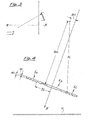
- - fig. 1 is a scheme of the asymmetrical lens in accordance with the invention;
- - fig. 2 is a view of the profile in accordance with the invention;
- - fig. 3 shows a detail of the Fresnel profile, either standard or modified;
- - fig. 4 is for the purposes of comparison a view of the pro file of a conventional Fresnel type lens madeup of various elements;
- - fig. 5 shows the solar images on the plane of maximum concentration from 9.00 hours to 15.00 hour for the Fresnel lens;
- - fig. 6 represents the solar images transmitted by a profile like the one illustrated in fig. 1 from 9.00 hours to 15.00 hours;
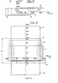
- - fig. 7 is a view of the profile in accordance with the invention, coupled to another identical profile.
- With reference to the figures in the accompanying drawings, and for the sake of simplicity, the behaviour of a profile in accordance with the invention, as illustrated in fig. 1 was assumed to be taken into consideration.
- The angle formed by the axis X of the refracted rays with the horizontal plane T is indicated by the letter α, while L designates the width of refractor R exposed to the sun.
- The common thickness.of the dioptric elements is indicated by the letters ei, while eo instead denotes the thickness of the substrate of said elements.
- The upper dioptric elements Es preferably making up the refractor in accordance with the invention are numbered from 1 to 6.
- The central dioptric element is indicated by Ec and the lower dioptric elements by Ei.
- The radius of curvature of a dioptric element is indicated by Ri while Xci and Yci indicate the co-ordinates of the central of curvature of said dioptric element.
- The letters Yi instead denote the distance of axis X from the first lower dioptric element Ei and from the first upper dioptric element Es respectively.
- The luminous rays A strike the plain or unprofiled surface of refractor R.
- They are transmitted through the profiles of the various elements of differing inclinations. It was found that during the first and last hours of the time period 9.00 hours to 15.00 hours considered, and above all at exactly 9.00 hours and at exactly 15.00 hours, while the upper elements Es limit, with respect to axis X, the excursion of the solar image in the downwards direction, the lower elements Ei, thanks to their greater dioptric power succeed more efficiently in straightening the sun's rays in the upwards direction.
- In the example considered, there was just one thickness ei of the elements, but two distinct focal points were chosen, namely at 800 mm for the upper elements Es and at 400 mm for the lower elements Ei.
- The focal point of a generic dioptric element, is taken to be the point of intersection of the refracted rays with axis x when the light strikes the exposed surface of the refractor at right angles.
- Of course, when the dioptric elements consist of elements of the modified type such point will degenerate into a segment.
- It has been found that the plane of maximum concentration lies in a position perpendicular to that of the profile (parallel to the plate) at a distance of 325.72 mm from the
origin 0 of the axis X, of separation between the upper elements and the lower elements. - The maximum ordinate towards the top (y negative) (fig. 6) reached on the collecting plane by the sun's rays is given by the ray refracted by the outermost end Q of the 6th upper element, while the minimum ordinate towards the bottom (y positive) is determined by-the outermost end of the central element (denoted by the letter P in fig. 2).
- It is precisely the higher dioptric power of the lower elements Ei with respect to that of each of the upper elements Es which gives the asymmetrical refractor the capacity do determine, on a preselected plane, a smaller excursion of the solar image with respect to that obtained with a normal Fresnel lens.
- In fact, in our example, the ratio between width L (fig.1) of the refractor and dimension L 1 (fig. 6) within which takes place the maximum excursion of the solar image, is between 2 and 2.1.
- Suppose we had, instead, a conventional Fresnel lens as illustrated in fig. 4 with a focal point lying at an intermediate distance between the two focal points of the two sets of elements (upper and lower) making up the lens as illustrated in figures 1 and 2, we would also obtain a plane of minimum dispersion of the solar image, but the concentra tion ratio on said plane would be 1.6 and not al least 2 as in the case of the profile according to the invention.
- The orientation of the profile in fig. 1 is East-West in the longitudinal direction of the lens, while the plane of tilt with respect to the horizontal plane will depend on the latitude of the locality where the lens is to be used.
- The refractors in figures 5 and 6 are consideted to be exposed perpendicularly to the sun's rays at 12.00'hours in the day of the summer solstice, at a latitude of 42° North.
- Application of a refractor_in accordance with the invention is not bound by the number, as several refractors can be used coupled together when deemed necessary (and as shown in fig. 7 which limits, for the sake of simplicity, the coupling of the refractors according to the invention to a total of two).
- The sum up, it should be exphasized that the refractor of asymmetrical profile can be made of any transparent material and can be of any dimensions; furthermore, thanks to its special concentrating power, the refractor possesses certain considerable advantages such as:
- - Fixed position both of the refractor and of the absorber.
- - Economy in the absorber design thanks to savings in materials and to the simplicity in construction.
- - Higher temperatures can be reached for any substance to the irradiated.
Claims (12)
characterized in that the elements making up said refractor consist of lenses having a Fresnel type profile, either standard or modified, with preferably identical thickness (ei), and capable of transmitting luminous rays with different inclinations.
characterized in that of the elements making up said refrac tor, the central element (Ec) consists of two flat- convex half lenses with different focal points and therefore said central element is afocal.
characterized in that of the elements making up said refrac tor, the lower elements (Ei) with respect to the axis of joint (X), that is the ones closest to the horizontal plane (T), all have a greater dioptric power than the dioptric power of the elements lying above the preselected axis of joint (X), whereby the upper elements (Es) limit the excursion of the solar image in the downwards direction, while the lower elements are able to straighten more efficiently the solar rays in the upwards direction.
characterized in that there are two distinct focal points for the upper (Es) and lower elements respectively making up said refractor.
in which the focal point chosen for the upper element (Es)is at 800 mm and that chosen for the lower elements is at 400 mm, where the focal point is defined as the point of intersection of the refracted rays with the preselected axis of joint when the light strikes the exposed refractor surface at right angles.
characterized in that said refractor is capable of concentrating the sun's rays to maximum extent on a plane lying parallel to said refractor, at a distance such that the maximum ordinate reached in'said plane in the upwards direction is given by the ray refracted from the outermost end of the 6th upper element, while the minimum ordinate in the downwards direction is given by the outermost end of the central element.
characterized in that said refractor is capable of concentrating the sun's rays on a plane of maximum concentrating lying parallel to said refractor at a distance of 325.72 mm.
characterized in that said refractor is capable of transmitt ing the sun's rays on to an underlying surface of considerab ly smaller dimensions than those of the refractor.
characterized in that the ratio between the width of the refractor profile (L) and the dimension (L ) within which takes place the maximum excursion of the solar energy on the collecting plane is equal to or greater than 2, and in all cases always greater than that obtainable under the same conditions with a Fresnel lens of the same dimensions and lying in the same position.
Applications Claiming Priority (2)
| Application Number | Priority Date | Filing Date | Title |
|---|---|---|---|
| IT21810/81A IT1138350B (en) | 1981-05-19 | 1981-05-19 | FIXED REFRACTOR WITH ASYMMETRIC PROFILE SUITABLE FOR CONCENTRATION OF SOLAR ENERGY ON AN APPROPRIATE COLLECTION PLAN |
| IT2181081 | 1981-05-19 |
Publications (3)
| Publication Number | Publication Date |
|---|---|
| EP0066112A2 true EP0066112A2 (en) | 1982-12-08 |
| EP0066112A3 EP0066112A3 (en) | 1983-07-27 |
| EP0066112B1 EP0066112B1 (en) | 1985-08-28 |
Family
ID=11187161
Family Applications (1)
| Application Number | Title | Priority Date | Filing Date |
|---|---|---|---|
| EP82103957A Expired EP0066112B1 (en) | 1981-05-19 | 1982-05-06 | Stationary optical longitudinal refractor |
Country Status (6)
| Country | Link |
|---|---|
| US (1) | US4530576A (en) |
| EP (1) | EP0066112B1 (en) |
| JP (1) | JPS5850502A (en) |
| DE (1) | DE3265775D1 (en) |
| ES (1) | ES512300A0 (en) |
| IT (1) | IT1138350B (en) |
Cited By (1)
| Publication number | Priority date | Publication date | Assignee | Title |
|---|---|---|---|---|
| FR2523279A1 (en) * | 1982-03-11 | 1983-09-16 | Siv Soc It Vetro | FIXED PRISMATIC REFRACTOR FOR CONCENTRATING SOLAR ENERGY ON A COLLECTING SURFACE |
Families Citing this family (5)
| Publication number | Priority date | Publication date | Assignee | Title |
|---|---|---|---|---|
| US5813744A (en) * | 1997-03-17 | 1998-09-29 | Mcdonnell Douglas Corp. | Aircraft ground floodlight |
| ITTO20030734A1 (en) * | 2003-09-24 | 2005-03-25 | Fiat Ricerche | MULTIFOCAL LIGHT CONCENTRATOR FOR A DEVICE FOR RADIATION CONVERSION, AND IN PARTICULAR FOR THE CONVERSION OF SOLAR RADIATION IN ELECTRICAL, THERMAL OR CHEMICAL ENERGY. |
| US8174776B2 (en) * | 2010-05-09 | 2012-05-08 | James P Campbell | Array of concentrating lenses and method of manufacture |
| US20190049150A1 (en) * | 2017-08-11 | 2019-02-14 | Do Sun Im | Solar energy collector |
| US20190048859A1 (en) * | 2017-08-11 | 2019-02-14 | Do Sun Im | Solar energy power generation system |
Citations (8)
| Publication number | Priority date | Publication date | Assignee | Title |
|---|---|---|---|---|
| US2290100A (en) * | 1940-08-30 | 1942-07-14 | Gen Motors Corp | Lens |
| GB602171A (en) * | 1945-01-26 | 1948-05-21 | Raleigh Cycle Company Ltd | Improvements in or relating to lamp glasses |
| GB969020A (en) * | 1960-04-01 | 1964-09-09 | Kockums Mekaniska Verkstads Ab | Improvements in or relating to drum lenses |
| US4011857A (en) * | 1975-11-24 | 1977-03-15 | Rice Harold D | Solar energy converter and elongated Fresnel lens element |
| FR2394766A1 (en) * | 1977-06-13 | 1979-01-12 | Latour Jean | Multi-faced transparent covers for trough pattern solar energy traps - to capture incident heat from various impingement angles |
| US4204881A (en) * | 1978-10-02 | 1980-05-27 | Mcgrew Stephen P | Solar power system |
| US4307711A (en) * | 1980-02-25 | 1981-12-29 | Doundoulakis George J | Sun tracking solar energy collector system |
| EP0050237A1 (en) * | 1980-09-30 | 1982-04-28 | SOCIETA ITALIANA VETRO - SIV SpA | Plate for covering a concentrating solar collector |
Family Cites Families (3)
| Publication number | Priority date | Publication date | Assignee | Title |
|---|---|---|---|---|
| US3064125A (en) * | 1957-09-30 | 1962-11-13 | Corning Glass Works | Luminair |
| US3797915A (en) * | 1971-01-20 | 1974-03-19 | Polaroid Corp | Binocular rangefinder-viewfinder with fresnel optics |
| JPS5834803B2 (en) * | 1978-03-14 | 1983-07-29 | 工業技術院長 | Concentrating solar cell device |
-
1981
- 1981-05-19 IT IT21810/81A patent/IT1138350B/en active
-
1982
- 1982-05-05 US US06/375,092 patent/US4530576A/en not_active Expired - Fee Related
- 1982-05-06 EP EP82103957A patent/EP0066112B1/en not_active Expired
- 1982-05-06 DE DE8282103957T patent/DE3265775D1/en not_active Expired
- 1982-05-18 ES ES512300A patent/ES512300A0/en active Granted
- 1982-05-19 JP JP57084687A patent/JPS5850502A/en active Pending
Patent Citations (8)
| Publication number | Priority date | Publication date | Assignee | Title |
|---|---|---|---|---|
| US2290100A (en) * | 1940-08-30 | 1942-07-14 | Gen Motors Corp | Lens |
| GB602171A (en) * | 1945-01-26 | 1948-05-21 | Raleigh Cycle Company Ltd | Improvements in or relating to lamp glasses |
| GB969020A (en) * | 1960-04-01 | 1964-09-09 | Kockums Mekaniska Verkstads Ab | Improvements in or relating to drum lenses |
| US4011857A (en) * | 1975-11-24 | 1977-03-15 | Rice Harold D | Solar energy converter and elongated Fresnel lens element |
| FR2394766A1 (en) * | 1977-06-13 | 1979-01-12 | Latour Jean | Multi-faced transparent covers for trough pattern solar energy traps - to capture incident heat from various impingement angles |
| US4204881A (en) * | 1978-10-02 | 1980-05-27 | Mcgrew Stephen P | Solar power system |
| US4307711A (en) * | 1980-02-25 | 1981-12-29 | Doundoulakis George J | Sun tracking solar energy collector system |
| EP0050237A1 (en) * | 1980-09-30 | 1982-04-28 | SOCIETA ITALIANA VETRO - SIV SpA | Plate for covering a concentrating solar collector |
Non-Patent Citations (4)
| Title |
|---|
| APPLIED OPTICS, vol. 19, no. 9, May 1980, pages 1439-1453, New York, USA * |
| JENAER RUNDSCHAU, 1966, pages 287-295 * |
| OPTICAL ENGINEERING, vol. 17, no. 3, 5th June 1978, Washington * |
| OPTICAL ENGINEERING, vol. 17, no. 3, 5th June 1978, Washington E.L. BURGESS et al.: A novel square fresnel lens design for illuminating circular solar cells, pages 299-300 * |
Cited By (1)
| Publication number | Priority date | Publication date | Assignee | Title |
|---|---|---|---|---|
| FR2523279A1 (en) * | 1982-03-11 | 1983-09-16 | Siv Soc It Vetro | FIXED PRISMATIC REFRACTOR FOR CONCENTRATING SOLAR ENERGY ON A COLLECTING SURFACE |
Also Published As
| Publication number | Publication date |
|---|---|
| IT1138350B (en) | 1986-09-17 |
| JPS5850502A (en) | 1983-03-25 |
| ES8305943A1 (en) | 1983-05-01 |
| ES512300A0 (en) | 1983-05-01 |
| DE3265775D1 (en) | 1985-10-03 |
| IT8121810A0 (en) | 1981-05-19 |
| EP0066112B1 (en) | 1985-08-28 |
| EP0066112A3 (en) | 1983-07-27 |
| US4530576A (en) | 1985-07-23 |
Similar Documents
| Publication | Publication Date | Title |
|---|---|---|
| US4069812A (en) | Solar concentrator and energy collection system | |
| US4456783A (en) | Multielement optical panel | |
| US7442871B2 (en) | Photovoltaic modules for solar concentrator | |
| US4459972A (en) | Heliostat assembly | |
| US3923381A (en) | Radiant energy collection | |
| US4003638A (en) | Radiant energy collection | |
| US4287880A (en) | Solar collector | |
| US4329021A (en) | Passive solar lighting system | |
| EP0222740B1 (en) | Solar energy collecting system using a primary reflector based on a pyramid structure | |
| CN1582378A (en) | Multiple reflector solar concentrators and systems | |
| RU2007118581A (en) | SOLAR COLLECTOR | |
| US20160079461A1 (en) | Solar generator with focusing optics including toroidal arc lenses | |
| US4765726A (en) | Fresnel scroll solar tracking device | |
| EP0066112A2 (en) | Stationary optical longitudinal refractor | |
| US4798444A (en) | Solar collection device | |
| US4050789A (en) | Tracking lens system for solar collectors and skylights | |
| US4124017A (en) | Collimating solar radiation collector | |
| Richter | Optics of a two-trough solar concentrator | |
| US20090301469A1 (en) | Solar collectors | |
| JPH0326801B2 (en) | ||
| JP3432168B2 (en) | Discontinuous line focusing lens | |
| US11226076B2 (en) | Solar light collecting and guiding system | |
| TWI693787B (en) | Flat-plate light collecting device | |
| McIntire | Elinination of the optical losses due to gaps between absorbers and their reflectors | |
| US4356814A (en) | Curvilinear solar energy collector |
Legal Events
| Date | Code | Title | Description |
|---|---|---|---|
| PUAI | Public reference made under article 153(3) epc to a published international application that has entered the european phase |
Free format text: ORIGINAL CODE: 0009012 |
|
| AK | Designated contracting states |
Designated state(s): BE CH DE FR NL |
|
| PUAL | Search report despatched |
Free format text: ORIGINAL CODE: 0009013 |
|
| AK | Designated contracting states |
Designated state(s): BE CH DE FR LI NL |
|
| 17P | Request for examination filed |
Effective date: 19830530 |
|
| GRAA | (expected) grant |
Free format text: ORIGINAL CODE: 0009210 |
|
| AK | Designated contracting states |
Designated state(s): BE CH DE FR LI NL |
|
| REF | Corresponds to: |
Ref document number: 3265775 Country of ref document: DE Date of ref document: 19851003 |
|
| ET | Fr: translation filed | ||
| PLBE | No opposition filed within time limit |
Free format text: ORIGINAL CODE: 0009261 |
|
| STAA | Information on the status of an ep patent application or granted ep patent |
Free format text: STATUS: NO OPPOSITION FILED WITHIN TIME LIMIT |
|
| 26N | No opposition filed | ||
| PGFP | Annual fee paid to national office [announced via postgrant information from national office to epo] |
Ref country code: BE Payment date: 19920505 Year of fee payment: 11 |
|
| PGFP | Annual fee paid to national office [announced via postgrant information from national office to epo] |
Ref country code: CH Payment date: 19920527 Year of fee payment: 11 |
|
| PGFP | Annual fee paid to national office [announced via postgrant information from national office to epo] |
Ref country code: NL Payment date: 19920531 Year of fee payment: 11 |
|
| PG25 | Lapsed in a contracting state [announced via postgrant information from national office to epo] |
Ref country code: LI Effective date: 19930531 Ref country code: CH Effective date: 19930531 Ref country code: BE Effective date: 19930531 |
|
| BERE | Be: lapsed |
Owner name: SOCIETA ITALIANA VETRO - SIV S.P.A. Effective date: 19930531 |
|
| PG25 | Lapsed in a contracting state [announced via postgrant information from national office to epo] |
Ref country code: NL Effective date: 19931201 |
|
| NLV4 | Nl: lapsed or anulled due to non-payment of the annual fee | ||
| REG | Reference to a national code |
Ref country code: CH Ref legal event code: PL |
|
| PGFP | Annual fee paid to national office [announced via postgrant information from national office to epo] |
Ref country code: FR Payment date: 19940429 Year of fee payment: 13 |
|
| PGFP | Annual fee paid to national office [announced via postgrant information from national office to epo] |
Ref country code: DE Payment date: 19940630 Year of fee payment: 13 |
|
| PG25 | Lapsed in a contracting state [announced via postgrant information from national office to epo] |
Ref country code: DE Effective date: 19960201 |
|
| PG25 | Lapsed in a contracting state [announced via postgrant information from national office to epo] |
Ref country code: FR Effective date: 19960229 |
|
| REG | Reference to a national code |
Ref country code: FR Ref legal event code: ST |
|
| REG | Reference to a national code |
Ref country code: FR Ref legal event code: ST |