EP0090167A2 - Fiber-optic sensor for a resonant element - Google Patents
Fiber-optic sensor for a resonant element Download PDFInfo
- Publication number
- EP0090167A2 EP0090167A2 EP83101517A EP83101517A EP0090167A2 EP 0090167 A2 EP0090167 A2 EP 0090167A2 EP 83101517 A EP83101517 A EP 83101517A EP 83101517 A EP83101517 A EP 83101517A EP 0090167 A2 EP0090167 A2 EP 0090167A2
- Authority
- EP
- European Patent Office
- Prior art keywords
- sensor
- resonant
- wire
- optical fiber
- resonant element
- Prior art date
- Legal status (The legal status is an assumption and is not a legal conclusion. Google has not performed a legal analysis and makes no representation as to the accuracy of the status listed.)
- Withdrawn
Links
Images
Classifications
-
- G—PHYSICS
- G01—MEASURING; TESTING
- G01L—MEASURING FORCE, STRESS, TORQUE, WORK, MECHANICAL POWER, MECHANICAL EFFICIENCY, OR FLUID PRESSURE
- G01L1/00—Measuring force or stress, in general
- G01L1/10—Measuring force or stress, in general by measuring variations of frequency of stressed vibrating elements, e.g. of stressed strings
- G01L1/103—Measuring force or stress, in general by measuring variations of frequency of stressed vibrating elements, e.g. of stressed strings optical excitation or measuring of vibrations
-
- G—PHYSICS
- G01—MEASURING; TESTING
- G01L—MEASURING FORCE, STRESS, TORQUE, WORK, MECHANICAL POWER, MECHANICAL EFFICIENCY, OR FLUID PRESSURE
- G01L1/00—Measuring force or stress, in general
- G01L1/08—Measuring force or stress, in general by the use of counterbalancing forces
Definitions
- This invention relates to improvements in industrial process measurement apparatus capable of developing a signal that corresponds to the magnitude of a measurable physical parameter. More particularly, this invention relates to such apparatus employing resonant element sensors with fiber optic means to excite the resonant element and sense the resonant frequency.
- Instrumentation systems for use in measuring industrial process variables such as flow, pressure, temperature, and liquid level typically employ a sensing element located in a field location adjacent the process which responds directly to the process variable.
- the output signal of the sensing element is transmitted to a distant central station, e. g ., a control room, for further signal conditioning and processing.
- a distant central station e. g ., a control room
- an electrical measurement signal is produced at the sensor, and a two-wire transmission line provides the interconnection necessary to power the sensor and receive the measurement signal.
- the present invention provides a significant departure from those industrial measurement instruments of the past by providing an optical link between a resonant sensing element adjacent the process and a distant central station containing signal conditioning electronics. Energy necessary to activate the sensing element and induce mechanical vibration is thus supplied optically.
- the other fiber senses oscillatory movement of the wire by reflecting transmitted steady-state light, which illuminates the moving wire, back into the fiber, thereby modulating the intensity of the steady-state light at a frequency that corresponds to the resonant frequency of the wire.
- a feedback network couples this composite reflected light signal to the supply of pulses to provide synchronization at the resonant frequency.
- the fiber optic link between the process sensor and the control room may be achieved with a single fiber. This preferably involves the use of wavelength multiplexing onto the single fiber to provide the function of powering the resonant-wire sensor and detecting its frequency of vibration.
- the term "resonant element” is to be construed broadly. That is, it is intended to encompass not only vibrating wires or strings but also any characteristic structure that, when subjected to an external stimulus such as a pressure or force, will vibrate at a frequency which corresponds to the applied stimulus.
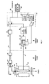
- FIG. 1 there is shown schematically a measuring instrument 10 employing a resonant element sensor 12 arranged to measure the magnitude of an unknown force (or pressure).
- the instrument is located in a process field 13 and is coupled by a pair of optical fibers 14, 15 to a central control room 16 having signal generating and processing equipment located therein.
- a central control room 16 having signal generating and processing equipment located therein.
- FIG. 1 shows in block diagram format the mechanical components of the resonant element sensor 12, namely a wire 20 tautly positioned within the gap 21 of a magnetic assembly.
- This assembly consists of a permanent magnet and suitable pole pieces (collectively indicated by numeral 22) arranged to produce an intense magnetic field perpendicular to the longitudinal axis of the wire.
- the wire 20 is anchored at one end to a section of the instrument body indicated by numeral 24, while the other end is operatively coupled to a diaphragm 26 which alters the tension on the wire in response to an applied force. While the exact arrangement of components is not important for an understanding of the principles of the present invention, the pressure measuring instrument for this embodiment is that disclosed in U.S. Patent No. 4,165,651, whose disclosure is hereby incorporated by reference.
- the wire is formed of electrically conductive material preferably with a polished reflective surface, and is electrically insulated from the instrument body by a bushing 23.
- a vibrating cycle is defined as a single excursion of the wire from its at rest or central null position to the left-most displacement back through the null position to its right-most displacement and back to the null position.
- the fiber 14 extends through a hole in the magnet assembly 22 to a position proximate the expected maximum deflection of the wire 20.
- This configuration permits the wire to be irradiated with light while a portion, depending on the instantaneous distance of the wire from the fiber, is reflected back into the fiber for transmission to the control room 16.
- the electro-optical circuitry within the control room 16 provides the system drive energy through a regulated d-c power supply 30 that delivers a voltage input to a light emitting diode (LED) 32 and a feedback network 50 which in turn powers a second LED 33.
- the LED 32 provides, in conjuction with a pair of microlenses 34, 35 and a beam splitter 40, steady-state light into the fiber 14 for transmission to the wire 20.
- the use of microlenses at optical interfaces throughout the system to enhance optical energy transfer is well understood by those of skill in the art and such lenses are commercially available from Nippon Sheet Glass Company.
- motion of the wire 20 results in a modulated light signal being reflected back to the control room 16 over the same optical fiber 14 where it is received at a photodiode 42 located at the return output 40A of the beam splitter 40.
- the electrical feedback network 50 coupled between the photodiode 42 and the LED 33 provides through a microlens 36 light energy for the optical fiber 15 to activate motion of the wire 20.
- a transformation of light energy into mechanical motion occurs at the field mounted end of the fiber 15 by a photodiode 62 whose electrical output is applied across the primary winding 64 of a transformer 66.
- the secondary winding 65 is directly connected to the wire 20.
- this overall arrangement although involving a mixture of electrical, mechanical and optical components, defines a closed loop oscillator.
- the system can be designed utilizing appropriate gain and phase shift selection to self-start from the electrical noise present or even from slight mechanical vibrations induced within the resonant-wire sensor 12 such that the loop will be at resonance within a few operating cycles.
- an a-c electrical signal will b.e developed at the photodiode 42 whose frequency is equal to that of the vibrating wire.
- This a-c signal is then applied to the feedback network 50.
- This network consists of a low-level a-c amplifier 52 to amplify the signal from the photodiode 42, a phase shift network 54 to compensate for phase differences within the closed loop to sustain oscillation, a pulse shaper 56, and a power amplifier 58.
- the output of the amplifier 58 becomes the drive voltage for the LED 33 which is thereby caused to emit a series of pulses of light.
- These light pulses transmitted via the optical fiber 15 to the photodiode 62, produce (after suitable impedance matching by the transformer 66) corresponding current pulses through the wire that are precisely synchronized with the motion of the wire to produce maximum deflection (and hence a maximum amplitude resonant signal) with each successive pulse.
- the output of the pulse shaper 56 represents the resonant frequency of vibration and hence the pressure measurement.
- This frequency signal may be read out directly at an output terminal 70 or alternatively supplied to a frequency to d-c converter 80 to produce a d-c control signal proportional to the pressure measurement.
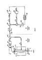
- FIG. 2 may be particularly advantageous which focuses primarily on the optical energy transfer of the present invention.
- a pair of LED sources 100, 200 of discernibly different wavelength ( ⁇ 1 , ⁇ 2 ) are wavelength multiplexed at a dichroic beam splitter 300.
- the source 100 produces a pulse train of light at a frequency within the operative range (e.g., 1700-3000 Hz) of the resonant sensor 10 while the source 200 provides a steady-state beam of light.
- the return signal reflected from the wire 20 is as before the steady-state beam ( ⁇ 2 ) modulated in intensity by an alternating signal corresponding to the motion of the wire. This signal is then detected at a photodiode 600 and fed back through a suitable network 700 to close the loop with the LED source 100 thereby setting the pulse train frequency at the resonant frequency of the wire.
- a single optical communication fiber may also be possible to utilize a single optical communication fiber to both power the sensor and detect its output without employing multiple sources and dichroic beam splitters.
- a pulsed beam of light is transmitted to the field and split in two paths, one to drive the wire, the other to illuminate the moving wire on a periodic basis.
- the waveforms of the reflected signal would be somewhat complicated due to the chopped nature of the incident light, the intensity of light reflected from the resonant wire would still be proportional to the distance between the wire and the adjacent optical fiber, with less light being reflected when the wire is furthest from the fiber and vice-versa.
- the returned illumination combined with the transmitted light produces a composite waveform representing the total illumination in a given instant of time within the optical fiber, i.e., a pulsed signal with a periodic alternating signal thereon, with suitable adjustments in the electronic design, a compatible oscillator could be built such that at resonance the transmitted light pulses would be synchronized with the motion of the wire.
- a compatible oscillator could be built such that at resonance the transmitted light pulses would be synchronized with the motion of the wire.
- An instrumentation system employing a resonant element sensor has been demonstrated that operates by converting light energy into resonant physical motion, while transmitting measurement data in terms of frequency through optical sensing means.
- a resonant element sensor By eliminating electrical transmission between control room and field locations over copper wire conductors, problems associated with electromagnetic interferences as in past such systems have been alleviated.
- Installation of the present optical network within process plants may be simplified by eliminating the need for separate optical fiber conductors for powering and sensing by effectively providing two-way communication over a single optical fiber.
- the feedback technique of the present invention besides sustaining oscillations also allows the largest amplitude of vibration for the lowest possible power input. This arrangement thus is particularly suitable to permit the use of low power LED sources for communicating over the distances involved while still maintaining an effective signal to noise ratio.
Abstract
Description
- This invention relates to improvements in industrial process measurement apparatus capable of developing a signal that corresponds to the magnitude of a measurable physical parameter. More particularly, this invention relates to such apparatus employing resonant element sensors with fiber optic means to excite the resonant element and sense the resonant frequency.
- Instrumentation systems for use in measuring industrial process variables such as flow, pressure, temperature, and liquid level typically employ a sensing element located in a field location adjacent the process which responds directly to the process variable. The output signal of the sensing element is transmitted to a distant central station, e.g., a control room, for further signal conditioning and processing. In the majority of present industrial applications, an electrical measurement signal is produced at the sensor, and a two-wire transmission line provides the interconnection necessary to power the sensor and receive the measurement signal.
- One class of measurement instrument for developing such a measurement signal that has been known for many years employs resonant elements as the primary sensing device. More recently an accurate, practical family of instruments of this general type has been devised and successfully marketed by The Foxboro Company as its 800-Series resonant wire sensors. While these devices represent a significant advance as evidenced by the high degree of commercial success which they have obtained, they do possess certain limitations, particularly when operating in severe, highly electrically noisy process environments.
- Thus, room for improvement exists in the design and construction of industrial measurement instruments, especially in their accuracy while operating within troublesome process environments, by eliminating or minimizing undesired electrical effects.
- The present invention provides a significant departure from those industrial measurement instruments of the past by providing an optical link between a resonant sensing element adjacent the process and a distant central station containing signal conditioning electronics. Energy necessary to activate the sensing element and induce mechanical vibration is thus supplied optically.
- In a preferred embodiment to be described in detail below, a differential pressure measurement instrument of the resonant-wire type is linked to a control room by optical fiber means. One fiber transmits pulsed optical energy to activate the resonant-wire sensor, whose tension and hence resonant frequency varies in accordance with the pressure to be measured, while a second fiber sends an information-bearing signal back to the control room representative of the pressure measurement. The transmitted pulsed optical energy is photovoltaic- ally converted into corresponding pulses of electric current which induce the wire, in the presence of a magnetic field, to vibrate at its resonant frequency. The other fiber senses oscillatory movement of the wire by reflecting transmitted steady-state light, which illuminates the moving wire, back into the fiber, thereby modulating the intensity of the steady-state light at a frequency that corresponds to the resonant frequency of the wire. To maintain the wire in resonance and thus minimize the amount of power required to drive the wire, a feedback network couples this composite reflected light signal to the supply of pulses to provide synchronization at the resonant frequency.
- Alternatively, the fiber optic link between the process sensor and the control room may be achieved with a single fiber. This preferably involves the use of wavelength multiplexing onto the single fiber to provide the function of powering the resonant-wire sensor and detecting its frequency of vibration.
- Other aspects and advantages of the present invention will become more evident after a review of the following detailed description taken in context with the accompanying drawings illustrating the principles of the invention.
-
- FIG. 1 is a schematic diagram in block format of a field-located differential pressure measurement device communicating with signal processing elements within a control room constructed in accordance with a preferred embodiment of the invention; and
- FIG. 2 is a schematic diagram showing the optical communications network employing a single fiber for transmitting power to and sensing the output of the pressure measurement device of FIG. 1.
- As used throughout this written description and in the appended claims, the term "resonant element" is to be construed broadly. That is, it is intended to encompass not only vibrating wires or strings but also any characteristic structure that, when subjected to an external stimulus such as a pressure or force, will vibrate at a frequency which corresponds to the applied stimulus.
- Turning now to FIG. 1, there is shown schematically a
measuring instrument 10 employing aresonant element sensor 12 arranged to measure the magnitude of an unknown force (or pressure). The instrument is located in aprocess field 13 and is coupled by a pair ofoptical fibers 14, 15 to acentral control room 16 having signal generating and processing equipment located therein. Although shown schematically as two distinct fiber optic cables, it will be appreciated that for typical process installations where the distance between field instruments and the control room is about one mile, these two fibers may be jacketed in a single cable with appropriate cladding to propagate the light. - The left-hand portion of FIG. 1 shows in block diagram format the mechanical components of the
resonant element sensor 12, namely awire 20 tautly positioned within thegap 21 of a magnetic assembly. This assembly consists of a permanent magnet and suitable pole pieces (collectively indicated by numeral 22) arranged to produce an intense magnetic field perpendicular to the longitudinal axis of the wire. - Although the operation of resonant element sensors is well understood by those of skill in the art, the following discussion represents a brief summary. The
wire 20 is anchored at one end to a section of the instrument body indicated bynumeral 24, while the other end is operatively coupled to adiaphragm 26 which alters the tension on the wire in response to an applied force. While the exact arrangement of components is not important for an understanding of the principles of the present invention, the pressure measuring instrument for this embodiment is that disclosed in U.S. Patent No. 4,165,651, whose disclosure is hereby incorporated by reference. The wire is formed of electrically conductive material preferably with a polished reflective surface, and is electrically insulated from the instrument body by a bushing 23. When an alternating electric current is caused to flow through the wire, it is induced to vibrate at its resonant frequency which in turn is a function of the applied pressure. For purposes of illustration, it is assumed that the magnetic field is directed through the wire orthogonally to the plane of the drawing sheet, and thus the wire displacement follows the profile given by the dashed lines. A vibrating cycle is defined as a single excursion of the wire from its at rest or central null position to the left-most displacement back through the null position to its right-most displacement and back to the null position. - As shown the fiber 14 extends through a hole in the
magnet assembly 22 to a position proximate the expected maximum deflection of thewire 20. This configuration permits the wire to be irradiated with light while a portion, depending on the instantaneous distance of the wire from the fiber, is reflected back into the fiber for transmission to thecontrol room 16. - In operation, the electro-optical circuitry within the
control room 16 provides the system drive energy through a regulatedd-c power supply 30 that delivers a voltage input to a light emitting diode (LED) 32 and afeedback network 50 which in turn powers asecond LED 33. TheLED 32 provides, in conjuction with a pair ofmicrolenses wire 20. The use of microlenses at optical interfaces throughout the system to enhance optical energy transfer is well understood by those of skill in the art and such lenses are commercially available from Nippon Sheet Glass Company. - As mentioned, motion of the
wire 20 results in a modulated light signal being reflected back to thecontrol room 16 over the same optical fiber 14 where it is received at aphotodiode 42 located at thereturn output 40A of the beam splitter 40. Theelectrical feedback network 50 coupled between thephotodiode 42 and theLED 33 provides through amicrolens 36 light energy for theoptical fiber 15 to activate motion of thewire 20. For this embodiment being described, a transformation of light energy into mechanical motion occurs at the field mounted end of thefiber 15 by aphotodiode 62 whose electrical output is applied across the primary winding 64 of atransformer 66. Thesecondary winding 65 is directly connected to thewire 20. - It will be appreciated that this overall arrangement, although involving a mixture of electrical, mechanical and optical components, defines a closed loop oscillator. Moreover, as is well known by those of skill in the art, the system can be designed utilizing appropriate gain and phase shift selection to self-start from the electrical noise present or even from slight mechanical vibrations induced within the resonant-
wire sensor 12 such that the loop will be at resonance within a few operating cycles. - Considering in more detail the operation of the system, and assuming that the
wire 20 has begun vibrating, an a-c electrical signal will b.e developed at thephotodiode 42 whose frequency is equal to that of the vibrating wire. This a-c signal is then applied to thefeedback network 50. This network consists of a low-level a-camplifier 52 to amplify the signal from thephotodiode 42, a phase shift network 54 to compensate for phase differences within the closed loop to sustain oscillation, apulse shaper 56, and apower amplifier 58. The output of theamplifier 58 becomes the drive voltage for theLED 33 which is thereby caused to emit a series of pulses of light. These light pulses, transmitted via theoptical fiber 15 to thephotodiode 62, produce (after suitable impedance matching by the transformer 66) corresponding current pulses through the wire that are precisely synchronized with the motion of the wire to produce maximum deflection (and hence a maximum amplitude resonant signal) with each successive pulse. Thus the output of thepulse shaper 56 represents the resonant frequency of vibration and hence the pressure measurement. This frequency signal may be read out directly at anoutput terminal 70 or alternatively supplied to a frequency tod-c converter 80 to produce a d-c control signal proportional to the pressure measurement. - In similar fashion changes to the resonant frequency of vibration caused by changes in pressure exerted on the
diaphragm 26 are detected and automatically adjusted for within the closed loop to produce a new output signal representative of the change in the process parameters. The design details of an appropriate amplifier circuit described above are well within the knowledge of a skilled artisan. - In certain applications it may be desirous to provide a single optical fiber for communication between the process field and the control room. For these purposes, the arrangement of FIG. 2 may be particularly advantageous which focuses primarily on the optical energy transfer of the present invention. For simplicity, details of the electronic drive and feedback circuitry have been omitted, suffice it to say their operation will be similar to that already presented in detail above. Here a pair of
LED sources dichroic beam splitter 300. Thesource 100 produces a pulse train of light at a frequency within the operative range (e.g., 1700-3000 Hz) of theresonant sensor 10 while thesource 200 provides a steady-state beam of light. These two wavelengths are transported from thecontrol room 16 over a singleoptical fiber 400 to a field-locateddichroic beam splitter 500 which passes substantially all of A 1 to thephotodiode 62 for powering thesensor 10 while blocking λ2, In turn, effectively all of the steady-state light (λ2) is reflected by thebeam splitter 500 so as to illuminate thewire 20, with essentially none of λ1 being directed along this path. - The return signal reflected from the
wire 20 is as before the steady-state beam (λ2) modulated in intensity by an alternating signal corresponding to the motion of the wire. This signal is then detected at aphotodiode 600 and fed back through asuitable network 700 to close the loop with theLED source 100 thereby setting the pulse train frequency at the resonant frequency of the wire. - It may also be possible to utilize a single optical communication fiber to both power the sensor and detect its output without employing multiple sources and dichroic beam splitters. In such an arrangement, a pulsed beam of light is transmitted to the field and split in two paths, one to drive the wire, the other to illuminate the moving wire on a periodic basis. Although the waveforms of the reflected signal would be somewhat complicated due to the chopped nature of the incident light, the intensity of light reflected from the resonant wire would still be proportional to the distance between the wire and the adjacent optical fiber, with less light being reflected when the wire is furthest from the fiber and vice-versa. The returned illumination combined with the transmitted light produces a composite waveform representing the total illumination in a given instant of time within the optical fiber, i.e., a pulsed signal with a periodic alternating signal thereon, with suitable adjustments in the electronic design, a compatible oscillator could be built such that at resonance the transmitted light pulses would be synchronized with the motion of the wire. Such source synchronization is arrived at by the feedback arrangement previously discussed in detail above.
- Thus numerous advantages of the present invention have been set forth in detail above. An instrumentation system employing a resonant element sensor has been demonstrated that operates by converting light energy into resonant physical motion, while transmitting measurement data in terms of frequency through optical sensing means. By eliminating electrical transmission between control room and field locations over copper wire conductors, problems associated with electromagnetic interferences as in past such systems have been alleviated. Installation of the present optical network within process plants may be simplified by eliminating the need for separate optical fiber conductors for powering and sensing by effectively providing two-way communication over a single optical fiber. Additionally, the feedback technique of the present invention besides sustaining oscillations also allows the largest amplitude of vibration for the lowest possible power input. This arrangement thus is particularly suitable to permit the use of low power LED sources for communicating over the distances involved while still maintaining an effective signal to noise ratio.
- Although a preferred embodiment of the invention has been described in detail above, this is solely for the purpose of illustration and is not intended to be limiting. Numerous modifications will become apparent to those of skill in the art. For example, the invention has been described throughout as operating with resonant element sensors that are activated by electro-magnetic energy and hence a conversion from light energy to electrical energy has been shown. It will be understood that other techniques could be devised for applying the supplied light energy to the sensor element to effect resonant physical motion without departing from the scope of the invention as defined in the accompanying claims.
Claims (4)
Applications Claiming Priority (2)
| Application Number | Priority Date | Filing Date | Title |
|---|---|---|---|
| US350687 | 1982-02-22 | ||
| US06/350,687 US4521684A (en) | 1982-02-22 | 1982-02-22 | Optical measurement system with light-driven vibrating sensor element |
Publications (2)
| Publication Number | Publication Date |
|---|---|
| EP0090167A2 true EP0090167A2 (en) | 1983-10-05 |
| EP0090167A3 EP0090167A3 (en) | 1984-08-29 |
Family
ID=23377776
Family Applications (1)
| Application Number | Title | Priority Date | Filing Date |
|---|---|---|---|
| EP83101517A Withdrawn EP0090167A3 (en) | 1982-02-22 | 1983-02-17 | Fiber-optic sensor for a resonant element |
Country Status (5)
| Country | Link |
|---|---|
| US (1) | US4521684A (en) |
| EP (1) | EP0090167A3 (en) |
| JP (1) | JPS58155320A (en) |
| AU (1) | AU551797B2 (en) |
| CA (1) | CA1196706A (en) |
Cited By (15)
| Publication number | Priority date | Publication date | Assignee | Title |
|---|---|---|---|---|
| GB2138137A (en) * | 1983-03-07 | 1984-10-17 | Brown Boveri Kent Ltd | Improvements in sensing apparatus |
| GB2144547A (en) * | 1983-08-04 | 1985-03-06 | Gen Electric Plc | A strain sensor |
| WO1985005178A1 (en) * | 1984-05-07 | 1985-11-21 | The Foxboro Company | Improved fiber optic remote sensor |
| GB2161931A (en) * | 1984-07-17 | 1986-01-22 | Stc Plc | Remote sensor systems |
| WO1986005271A1 (en) * | 1985-02-27 | 1986-09-12 | University Of Strathclyde | A measuring device |
| WO1987000618A1 (en) * | 1985-07-16 | 1987-01-29 | The Foxboro Company | Method and apparatus for sensing a measurand |
| GB2178537A (en) * | 1985-06-28 | 1987-02-11 | Simmonds Precision Products | Liquid gauging system |
| GB2185106A (en) * | 1985-12-13 | 1987-07-08 | Gen Electric Co Plc | An optically-driven vibrating sensor |
| GB2187551A (en) * | 1986-03-04 | 1987-09-09 | Gen Electric Co Plc | Radiation detector |
| GB2194049A (en) * | 1986-08-15 | 1988-02-24 | Gen Electric Co Plc | A photoacoustic measuring device |
| GB2197069A (en) * | 1986-11-03 | 1988-05-11 | Stc Plc | Optically driven sensor device |
| WO1989000677A1 (en) * | 1986-07-21 | 1989-01-26 | The Foxboro Company | Self-oscillating, optical resonant sensor |
| EP0428263A1 (en) * | 1989-10-17 | 1991-05-22 | Lucas Industries Public Limited Company | Vibrating sensor |
| CN107063311A (en) * | 2017-04-21 | 2017-08-18 | 江西飞尚科技有限公司 | A kind of dynamic measurement system method of single coil vibrating sensor |
| CN109743644A (en) * | 2018-12-29 | 2019-05-10 | 上海建工集团股份有限公司 | Vibratory string acquisition device and method |
Families Citing this family (29)
| Publication number | Priority date | Publication date | Assignee | Title |
|---|---|---|---|---|
| US4743752A (en) * | 1984-05-07 | 1988-05-10 | The Foxboro Company | Fiber optic remote sensor |
| WO1988002109A1 (en) * | 1986-09-15 | 1988-03-24 | Hughes Aircraft Company | System for sensing ions in aqueous solution |
| GB8705151D0 (en) * | 1987-03-05 | 1987-04-08 | Univ Strathclyde | Optically excited vibratile transducer |
| US5031987A (en) * | 1990-01-02 | 1991-07-16 | Sundstrand Data Control, Inc. | Fiber optic thermal switch utilizing frustrated total internal reflection readout |
| US5258868A (en) * | 1990-02-02 | 1993-11-02 | Rosemount Inc. | Optical process variable transmitter |
| US5528409A (en) * | 1994-10-13 | 1996-06-18 | Nt International, Inc. | Fiber-optic interface system |
| US5727110A (en) * | 1995-09-29 | 1998-03-10 | Rosemount Inc. | Electro-optic interface for field instrument |
| US5771114A (en) * | 1995-09-29 | 1998-06-23 | Rosemount Inc. | Optical interface with safety shutdown |
| SE513392C2 (en) | 1998-05-26 | 2000-09-04 | Carl Tyren | Method and device for contactless detection via modulation of electromagnetic signal by measuring magnitude controlled mechanical resonance |
| US6855115B2 (en) * | 2002-01-22 | 2005-02-15 | Cardiomems, Inc. | Implantable wireless sensor for pressure measurement within the heart |
| US7699059B2 (en) | 2002-01-22 | 2010-04-20 | Cardiomems, Inc. | Implantable wireless sensor |
| GB0201916D0 (en) * | 2002-01-29 | 2002-03-13 | Advanced Laser Solutions Ltd | Method and apparatus for monitoring light beams |
| US7147604B1 (en) | 2002-08-07 | 2006-12-12 | Cardiomems, Inc. | High Q factor sensor |
| US7245117B1 (en) | 2004-11-01 | 2007-07-17 | Cardiomems, Inc. | Communicating with implanted wireless sensor |
| EP1677852A4 (en) * | 2003-09-16 | 2009-06-24 | Cardiomems Inc | Implantable wireless sensor |
| US8026729B2 (en) | 2003-09-16 | 2011-09-27 | Cardiomems, Inc. | System and apparatus for in-vivo assessment of relative position of an implant |
| US7466120B2 (en) * | 2004-11-01 | 2008-12-16 | Cardiomems, Inc. | Communicating with an implanted wireless sensor |
| US7647836B2 (en) * | 2005-02-10 | 2010-01-19 | Cardiomems, Inc. | Hermetic chamber with electrical feedthroughs |
| US20060174712A1 (en) * | 2005-02-10 | 2006-08-10 | Cardiomems, Inc. | Hermetic chamber with electrical feedthroughs |
| US8118749B2 (en) * | 2005-03-03 | 2012-02-21 | Cardiomems, Inc. | Apparatus and method for sensor deployment and fixation |
| US8021307B2 (en) | 2005-03-03 | 2011-09-20 | Cardiomems, Inc. | Apparatus and method for sensor deployment and fixation |
| US7621036B2 (en) * | 2005-06-21 | 2009-11-24 | Cardiomems, Inc. | Method of manufacturing implantable wireless sensor for in vivo pressure measurement |
| AU2006262287A1 (en) | 2005-06-21 | 2007-01-04 | Cardiomems, Inc. | Method of manufacturing implantable wireless sensor for in vivo pressure measurement |
| CN103389176B (en) * | 2013-07-25 | 2015-08-12 | 国家电网公司 | A kind of Transformer Winding width is to stress measurement device and measuring method |
| CN109579897A (en) * | 2018-12-12 | 2019-04-05 | 上海兰宝传感科技股份有限公司 | A kind of Intelligent hand-held readout instrument applied to geotechnical engineering |
| CN110702150A (en) * | 2019-10-11 | 2020-01-17 | 贵州省质安交通工程监控检测中心有限责任公司 | Optimized sweep frequency excitation method for vibrating wire collector |
| CN110926520B (en) * | 2019-11-08 | 2020-11-10 | 中国水利水电科学研究院 | Automatic data acquisition system of low-insulation vibrating wire sensor |
| CN112985646B (en) * | 2021-02-07 | 2021-11-19 | 华南理工大学 | Steel strand outer wire tensioning device and inner and outer wire limit friction force measuring device and method |
| CN114636465A (en) * | 2022-03-22 | 2022-06-17 | 中国计量科学研究院 | Radio frequency counting device for nucleic acid extractor of photoelectric sensor |
Citations (4)
| Publication number | Priority date | Publication date | Assignee | Title |
|---|---|---|---|---|
| GB1480702A (en) * | 1975-02-20 | 1977-07-20 | Rucker Co | Continuous cable tension monitor |
| DE2945019A1 (en) * | 1978-11-16 | 1980-05-29 | Asea Ab | FIBER OPTICAL MEASURING DEVICE FOR MEASURING PHYSICAL SIZES |
| JPS56112622A (en) * | 1980-02-10 | 1981-09-05 | Toshiba Corp | Power detector |
| EP0041668A2 (en) * | 1980-06-09 | 1981-12-16 | Asea Ab | Fiber optical measuring device |
Family Cites Families (7)
| Publication number | Priority date | Publication date | Assignee | Title |
|---|---|---|---|---|
| US4071753A (en) * | 1975-03-31 | 1978-01-31 | Gte Laboratories Incorporated | Transducer for converting acoustic energy directly into optical energy |
| US4372164A (en) * | 1980-06-02 | 1983-02-08 | The Foxboro Company | Industrial process control instrument employing a resonant sensor |
| DE3021712A1 (en) * | 1980-06-10 | 1982-01-07 | Hoechst Ag, 6000 Frankfurt | USE OF ESTERESTED OXALKYLATES OF AROMATIC HYDROXY COMPOUNDS FOR PREPARING COLORANTS AND CORRESPONDING COLORANT PREPARATIONS |
| SE422111B (en) * | 1980-06-23 | 1982-02-15 | Asea Ab | FIBEROPTIC COUPLET METDON |
| US4346478A (en) * | 1980-12-01 | 1982-08-24 | Siemens Corporation | Fiber optical sensor system, preferably for measuring physical parameters |
| US4356396A (en) * | 1980-12-17 | 1982-10-26 | Siemens Corporation | Fiber optical measuring device with compensating properties |
| US4379226A (en) * | 1981-02-02 | 1983-04-05 | Siemens Corporation | Method and sensor device for measuring a physical parameter utilizing an oscillatory, light modulation element |
-
1982
- 1982-02-22 US US06/350,687 patent/US4521684A/en not_active Expired - Fee Related
-
1983
- 1983-02-17 EP EP83101517A patent/EP0090167A3/en not_active Withdrawn
- 1983-02-17 AU AU11604/83A patent/AU551797B2/en not_active Ceased
- 1983-02-21 JP JP58027505A patent/JPS58155320A/en active Pending
- 1983-02-21 CA CA000422005A patent/CA1196706A/en not_active Expired
Patent Citations (4)
| Publication number | Priority date | Publication date | Assignee | Title |
|---|---|---|---|---|
| GB1480702A (en) * | 1975-02-20 | 1977-07-20 | Rucker Co | Continuous cable tension monitor |
| DE2945019A1 (en) * | 1978-11-16 | 1980-05-29 | Asea Ab | FIBER OPTICAL MEASURING DEVICE FOR MEASURING PHYSICAL SIZES |
| JPS56112622A (en) * | 1980-02-10 | 1981-09-05 | Toshiba Corp | Power detector |
| EP0041668A2 (en) * | 1980-06-09 | 1981-12-16 | Asea Ab | Fiber optical measuring device |
Non-Patent Citations (2)
| Title |
|---|
| CONTROL AND INSTRUMENTATION, vol. 13, no. 3, March 1981, pages 45,47, London, GB; J. BROTTON: "Remote sensing could emerge as a major role for fibre optics". * |
| PATENTS ABSTRACTS OF JAPAN, vol. 5, no. 185 (P-91)[857], 25th November 1981; & JP-A-56 112 622 (TOKYO SHIBAURA DENKI K.K.) 05-09-1981 * |
Cited By (23)
| Publication number | Priority date | Publication date | Assignee | Title |
|---|---|---|---|---|
| GB2138137A (en) * | 1983-03-07 | 1984-10-17 | Brown Boveri Kent Ltd | Improvements in sensing apparatus |
| US4651571A (en) * | 1983-08-04 | 1987-03-24 | Fisher Controls International, Inc. | Strain sensor |
| GB2144547A (en) * | 1983-08-04 | 1985-03-06 | Gen Electric Plc | A strain sensor |
| WO1985005178A1 (en) * | 1984-05-07 | 1985-11-21 | The Foxboro Company | Improved fiber optic remote sensor |
| GB2161931A (en) * | 1984-07-17 | 1986-01-22 | Stc Plc | Remote sensor systems |
| WO1986005271A1 (en) * | 1985-02-27 | 1986-09-12 | University Of Strathclyde | A measuring device |
| GB2178537A (en) * | 1985-06-28 | 1987-02-11 | Simmonds Precision Products | Liquid gauging system |
| US4713540A (en) * | 1985-07-16 | 1987-12-15 | The Foxboro Company | Method and apparatus for sensing a measurand |
| WO1987000618A1 (en) * | 1985-07-16 | 1987-01-29 | The Foxboro Company | Method and apparatus for sensing a measurand |
| GB2185106A (en) * | 1985-12-13 | 1987-07-08 | Gen Electric Co Plc | An optically-driven vibrating sensor |
| GB2185106B (en) * | 1985-12-13 | 1990-04-25 | Gen Electric Plc | A sensor |
| US4772786A (en) * | 1985-12-13 | 1988-09-20 | The General Electric Company, P.L.C. | Photothermal oscillator force sensor |
| GB2187551B (en) * | 1986-03-04 | 1990-03-14 | Gen Electric Plc | Radiation detector |
| GB2187551A (en) * | 1986-03-04 | 1987-09-09 | Gen Electric Co Plc | Radiation detector |
| WO1989000677A1 (en) * | 1986-07-21 | 1989-01-26 | The Foxboro Company | Self-oscillating, optical resonant sensor |
| GB2194049A (en) * | 1986-08-15 | 1988-02-24 | Gen Electric Co Plc | A photoacoustic measuring device |
| GB2194049B (en) * | 1986-08-15 | 1990-04-25 | Gen Electric Plc | A sensor |
| GB2197069A (en) * | 1986-11-03 | 1988-05-11 | Stc Plc | Optically driven sensor device |
| GB2197069B (en) * | 1986-11-03 | 1990-10-24 | Stc Plc | Sensor device |
| EP0428263A1 (en) * | 1989-10-17 | 1991-05-22 | Lucas Industries Public Limited Company | Vibrating sensor |
| CN107063311A (en) * | 2017-04-21 | 2017-08-18 | 江西飞尚科技有限公司 | A kind of dynamic measurement system method of single coil vibrating sensor |
| CN109743644A (en) * | 2018-12-29 | 2019-05-10 | 上海建工集团股份有限公司 | Vibratory string acquisition device and method |
| CN109743644B (en) * | 2018-12-29 | 2021-11-09 | 上海建工集团股份有限公司 | Vibrating wire collecting device and method |
Also Published As
| Publication number | Publication date |
|---|---|
| CA1196706A (en) | 1985-11-12 |
| US4521684A (en) | 1985-06-04 |
| JPS58155320A (en) | 1983-09-16 |
| AU1160483A (en) | 1983-09-01 |
| AU551797B2 (en) | 1986-05-08 |
| EP0090167A3 (en) | 1984-08-29 |
Similar Documents
| Publication | Publication Date | Title |
|---|---|---|
| US4521684A (en) | Optical measurement system with light-driven vibrating sensor element | |
| US4743752A (en) | Fiber optic remote sensor | |
| KR940011933B1 (en) | Method and apparatus for sensing a measurand | |
| US4379226A (en) | Method and sensor device for measuring a physical parameter utilizing an oscillatory, light modulation element | |
| US4651571A (en) | Strain sensor | |
| US4857727A (en) | Optically powered remote sensors with timing discrimination | |
| GB2146123A (en) | Apparatus for monitoring displacement | |
| EP0244087A2 (en) | Remote temperature-compensated pressure sensor | |
| US6018386A (en) | Oscillatory, optically coupled measurement system | |
| AU575193B2 (en) | Improved fiber optic remote sensor | |
| US5010770A (en) | Vibrating tube fiber optic pressure transducer with light-powered electro-magnetic drive | |
| JPH04263399A (en) | Measuring apparatus based on transmission of non-electric signal and energy | |
| JPS6133451B2 (en) | ||
| GB2259420B (en) | A sensor | |
| US4955238A (en) | Optical sensor | |
| JPH0752118B2 (en) | measuring device | |
| CA1233664A (en) | Improved fiber optic remote sensor | |
| US4899044A (en) | Optically coupled remote sensor apparatus and system | |
| CA1231851A (en) | Strain sensor | |
| Spooncer et al. | Hybrid optical fibre sensors | |
| GB2328278A (en) | Piezo-electric current monitor | |
| Hale et al. | Optical Fibre Systems For Offshore Monitoring And Control | |
| CN85104639A (en) | Improved fiber optic remote sensor | |
| CS244494B1 (en) | Device for luminous flux modulation in optical fibrous pick-up | |
| Dakin | Optical fibre hydrophones and hydrophone arrays |
Legal Events
| Date | Code | Title | Description |
|---|---|---|---|
| PUAI | Public reference made under article 153(3) epc to a published international application that has entered the european phase |
Free format text: ORIGINAL CODE: 0009012 |
|
| AK | Designated contracting states |
Designated state(s): DE FR GB IT NL |
|
| PUAL | Search report despatched |
Free format text: ORIGINAL CODE: 0009013 |
|
| AK | Designated contracting states |
Designated state(s): DE FR GB IT NL |
|
| 17P | Request for examination filed |
Effective date: 19850205 |
|
| 17Q | First examination report despatched |
Effective date: 19860131 |
|
| RAP1 | Party data changed (applicant data changed or rights of an application transferred) |
Owner name: THE FOXBORO COMPANY |
|
| R17C | First examination report despatched (corrected) |
Effective date: 19870416 |
|
| STAA | Information on the status of an ep patent application or granted ep patent |
Free format text: STATUS: THE APPLICATION IS DEEMED TO BE WITHDRAWN |
|
| 18D | Application deemed to be withdrawn |
Effective date: 19880108 |
|
| RIN1 | Information on inventor provided before grant (corrected) |
Inventor name: LEWIS, EDWARD L. Inventor name: OLSEN, EVERETT O. Inventor name: GILBY, ANTHONY C. |