EP0092338A2 - Fiber optic connector housing - Google Patents
Fiber optic connector housing Download PDFInfo
- Publication number
- EP0092338A2 EP0092338A2 EP83301902A EP83301902A EP0092338A2 EP 0092338 A2 EP0092338 A2 EP 0092338A2 EP 83301902 A EP83301902 A EP 83301902A EP 83301902 A EP83301902 A EP 83301902A EP 0092338 A2 EP0092338 A2 EP 0092338A2
- Authority
- EP
- European Patent Office
- Prior art keywords
- housing
- fiber optic
- profiled bore
- section
- printed circuit
- Prior art date
- Legal status (The legal status is an assumption and is not a legal conclusion. Google has not performed a legal analysis and makes no representation as to the accuracy of the status listed.)
- Granted
Links
Images
Classifications
-
- G—PHYSICS
- G02—OPTICS
- G02B—OPTICAL ELEMENTS, SYSTEMS OR APPARATUS
- G02B6/00—Light guides; Structural details of arrangements comprising light guides and other optical elements, e.g. couplings
- G02B6/24—Coupling light guides
- G02B6/42—Coupling light guides with opto-electronic elements
- G02B6/4292—Coupling light guides with opto-electronic elements the light guide being disconnectable from the opto-electronic element, e.g. mutually self aligning arrangements
-
- G—PHYSICS
- G02—OPTICS
- G02B—OPTICAL ELEMENTS, SYSTEMS OR APPARATUS
- G02B6/00—Light guides; Structural details of arrangements comprising light guides and other optical elements, e.g. couplings
- G02B6/24—Coupling light guides
- G02B6/42—Coupling light guides with opto-electronic elements
- G02B6/4201—Packages, e.g. shape, construction, internal or external details
- G02B6/4266—Thermal aspects, temperature control or temperature monitoring
- G02B6/4268—Cooling
- G02B6/4269—Cooling with heat sinks or radiation fins
Abstract
Description
- This invention relates to connector housings and more particularly to housings mountable on printed circuit boards to interconnect electro-optic devices and fiber optic connectors.
- It is known to mount a housing on a printed circuit board and in a profiled bore of which is disposed a ferrule member. A metal clip member secures the ferrule member within the profiled bore by being itself secured onto the housing and also operates as a heat sink for an electro-optic member within the ferrule member. A fiber optic connector including a ferrule member terminated onto a fiber optic transmission member is securably connected to the housing within the profiled bore to interconnect the electro-optic member and the fiber optic transmission member. The housing, ferrule member, metal clip, and electro-optic member are all secured together as a device mountable onto a printed circuit board with no latching members for latchably securing a ferrule member of a fiber optic connector within the housing.
- According to the present invention, a housing member has a profiled bore extending therethrough in one section of which a ferrule member containing an electro-optic member is secured by a removable retaining clip member that also acts as a heat sink member. Another ferrule member of a fiber optic connector terminated onto a fiber optic transmission member is disposed in another section of the profiled bore and is latchably secured therein by spring latching members secured in the housing.
- According to another aspect of the present invention, the spring latching members have legs that are frictionally disposed in holes in a printed circuit board to secure the housing in position on the board prior to being soldered in place thereon.
-
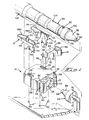
- FIGURE 1 is a perspective, exploded view of a housing and its parts for interconnecting ferrule members to form a fiber optic connection.
- FIGURE 2 is a perspective view showing the housing and parts assembled and mounted on a printed circuit board with fiber optic connectors latchably secured therein.
- FIGURE 3 is a part top plan view of the housing with a part of the housing broken away showing the latching members in engagement with the ferrule member of the fiber optic connector.
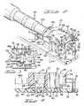
- FIGURE 4 is a view taken along line 4-4 of Figure 2.
- Figures 1 through 4 illustrate the invention which comprises a
housing member 10,spring latching members 12, and retainingclip 14.Housing member 10 is preferably molded from a suitable plastic material and has aprofiled bore 16 extending therethrough in the form of frustoconical sections at each end thereof with a cylindrical section interconnecting the frustoconical sections. The entrance to one end ofprofiled bore 16 has a substantiallyannular recess 18 which has a flat keying surface therein, whereas the other end ofprofiled bore 16 has a substantiallyannular recess 20 also with a flat keying surface therein. Stopsurfaces annular recess 18 with the frustoconical section and annular 20 and the intersection of the frustoconical section of profile bore 16. -
Slots 26 extend throughhousing member 10 and have smaller dimensionedsections 28 withstop surfaces 30 separating the larger and smaller sections ofslots 26.Openings 32 are located in the sidewalls ofhousing member 10 and are in communication with the larger sections ofslots 26 and they terminate at the position ofstop surfaces 30.Openings 32 extend along the walls ofprojections 34 that extend outwardly from the sides ofhousing member 10. Recesses 36, 38 extend inwardly from the sides ofhousing member 10 and are parallel to one another.Projections housing member 10 withannular projections 44 extending outwardly fromprojections 42 and concentric therewith. -
Latching members 12 are stamped and formed from a suitable metal having desirable spring characteristics and eachlatching member 12 includes amounting section 46 from which extends aspring member 48 which includes a curved-back section 48A extending towardmounting section 46 and terminating in an inwardly-directedend 50.Projections 52 extend outwardly from the top ofmounting sections 46.Mounting legs 54 extend outwardly from mountingsections 46 and containarcuate projections 56 adjacent the outer ends thereof. -
Latching members 12 are securely mounted inslots 26 ofhousing member 10 withmounting sections 46 positioned in the larger sections ofslots 26 and bottoming againststop surfaces 30 withmounting legs 54 extending through thesmaller sections 28 ofslots 26 and extending outwardly beyond the bottom surface ofhousing member 10.Spring members 48 extend outwardly throughopenings 32 ofhousing member 10 and extend along the sides thereof with the curved-back sections 48A extending towardannular recess 18 and terminating adjacent thereto with inwardly-directedends 50 being positioned adjacentannular recess 18.Projections 52 bite intohousing member 10 thereby securing latchingmembers 12 therewithin. - After
spring latching members 12 have been secured withinslots 26 ofhousing member 10,housing member 10 can now be mounted onto printedcircuit board 58 witharcuate projections 56 ofmounting legs 54 frictionally disposed inholes 60 in printedcircuit board 58 whileannular projections 44 are positioned withinholes 62 therein.Arcuate projections 56 frictionally engage the walls ofholes 60 thereby securinghousing member 10 in position on printedcircuit board 58 and mountinglegs 54 extend slightly below ametal section 78 secured toboard 58 to which mountinglegs 54 are soldered thereby permanently securinghousing member 10 on printedcircuit board 58.Projections position housing member 10 away from printedcircuit board 58 for cleaning purposes. -
Housing member 10 is mounted, on printedcircuit board 58 adjacent electro-optic device 64 of the type disclosed in U.S. Patent No. 4,186,996, the disclosure of which is completely incorporated herein by reference. Electro-optic device 64 can be either a light-transmitting device or a light-receiving device which is encapsulated within a ferrule member formed from a suitable plastic have resilient characteristics that enables the front end having afrustoconical section 66 andcylindrical section 68 to be resiliently mated within the corresponding frustQconical and cylindrical sections of profiledbore 16 withannular section 70 being disposed withinrecess 20. Aflat surface 72 onannular section 70 mates with a corresponding flat surface withinannular recess 20 to key the positioning of electro-optic device 64 within theprofiled bore 16 ofhousing member 10. Electrical leads 74 of electro-optic device 64 are electrically connected toconductive paths 76 on printedcircuit board 58. Whenelectrical leads 74 are flow-soldered toconductive paths 76, mountinglegs 54 are also soldered tometal section 78 secured to printedcircuit board 58 thereby securinghousing member 10 on printedcircuit board 58. The heat from the flow-soldering operation may deformprojections 44 in such a way as to expand the end ofprojections 44 thereby rivetingprojections 44 to printedcircuit board 58 thereby providing an additional securing arrangement. - Retaining
clip 14 is stamped and formed from a suitable metal having spring characteristics and includes abody section 80 having a U-shaped opening 82 therein which clearselectrical lead 74 whenbody section 80 is disposed against electro-optic device 64. Astop member 84 is at right angles tobody section 80 and engageshousing member 10 to position retainingclip 14 thereon.Spring arms 86 extend outwardly frombody section 80 and inwardly-directedends 88 which are slideably disposed inrecesses 38 when retainingclip 14 is moved into a retaining position onhousing member 10 to retain electro-optic device 64 withinhousing member 10 and to apply an axial force thereto to properly resiliently seatfrustoconical section 66 andcylindrical section 68 within the corresponding sections of profiledbore 16 as a result ofbody section 80 engaging the rear surface of electro-optic device 64. - If desired,
housing member 10 can be inserted within a rectangular opening of a mounting panel withprojections 34 engaging one surface of the panel and a U-shaped clip (not shown) has its legs positioned withinrecesses 36 to retainhousing member 10 in position within the opening of the panel. - Fiber
optic connector 90 includes aplastic ferrule member 92 into which a fiber optic transmission member is positioned withtransmission core member 94 having its end coincident with the end ofcylindrical section 96.Frustoconical section 98 extends betweencylindrical section 96 andannular section 100 which has aflat surface 102.Metal crimping ferrule 104 is crimped ontoferrule 92 and ontoouter jacket 106 of the fiber optic transmission member thereby effectively terminating the fiber optic transmission member. The plastic material of whichferrule member 92 is made is suitably resilient so thatfrustoconical section 98 andcylindrical section 96 mateably and resiliently engage corresponding frustoconical section and cylindrical section of profiledbore 16 ofhousing member 10 when they are inserted thereinto thereby effecting an operable interconnection between fiberoptic connector 90 and electro-optic device 64. Fiberoptic connector 90 is latchably secured within the profiled bore ofhousing member 10 by means ofspring members 48 with inwardly-directedends 50 engaging onto the rear surface ofannular section 100 as illustrated in Figure 3 withannular section 100 fitting withinannular recess 18 andflat surface 102 keyingly engaging the flat surface withinrecess 18.Spring members 48 are cammed outwardly when fiberoptic connector 90 is being inserted intohousing member 10 so that fiberoptic connector 90 can be inserted intohousing member 10 with low force and is removed fromhousing member 10 with substantially higher forces. Plasticferrule member 92 is of the type disclosed in U.S. Patent No. 3,999,837, the disclosure of which is completely incorporated herein by reference. - Instead of electro-
optic device 64 being positioned inrecess 20 ofhousing member 10, a metal can type of electro-optic device identified as TO-18/46 can be bonded withinrecess 20. A TO-18 electro-optic device having a plastic cap is press fitted intorecess 20. Retainingclip 14 serves the dual function of retaining the electro-optic device in position inhousing member 10 and also defines a heat sink to carry heat away therefrom. , - If desired, another fiber optic connector similar to that of fiber
optic connector 90 can be positioned withinrecess 20 ofhousing member 10 and retained therein by retainingclip 14 to provide an optical coupling device for optically coupling the terminated ends of fiber optic transmission members.
Claims (5)
latching members (12) have mounting sections (46) secured in said housing and spring members (48) extending outwardly from said mounting sections (46) and forwardly of one end of said housing and curving back toward one entrance to said profiled bore, inwardly-directed ends (50) of said spring members positioned adjacent said one entrance and engageable onto a shoulder (100) of a ferrule member (92) of a fiber optic connector (90) that has been positioned into said profiled bore (16).
Applications Claiming Priority (2)
| Application Number | Priority Date | Filing Date | Title |
|---|---|---|---|
| US06/368,949 US4547039A (en) | 1982-04-16 | 1982-04-16 | Housing mountable on printed circuit board to interconnect fiber optic connectors |
| US368949 | 1982-04-16 |
Publications (3)
| Publication Number | Publication Date |
|---|---|
| EP0092338A2 true EP0092338A2 (en) | 1983-10-26 |
| EP0092338A3 EP0092338A3 (en) | 1985-11-06 |
| EP0092338B1 EP0092338B1 (en) | 1990-01-17 |
Family
ID=23453429
Family Applications (1)
| Application Number | Title | Priority Date | Filing Date |
|---|---|---|---|
| EP83301902A Expired - Lifetime EP0092338B1 (en) | 1982-04-16 | 1983-04-05 | Fiber optic connector housing |
Country Status (8)
| Country | Link |
|---|---|
| US (1) | US4547039A (en) |
| EP (1) | EP0092338B1 (en) |
| JP (1) | JPS58187908A (en) |
| BR (1) | BR8301436A (en) |
| CA (1) | CA1222895A (en) |
| DE (1) | DE3381120D1 (en) |
| IE (1) | IE55336B1 (en) |
| MX (1) | MX159903A (en) |
Cited By (5)
| Publication number | Priority date | Publication date | Assignee | Title |
|---|---|---|---|---|
| WO1987003969A1 (en) * | 1985-12-26 | 1987-07-02 | Amp Incorporated | Optical fiber connector |
| WO1997007420A1 (en) * | 1995-08-21 | 1997-02-27 | Telefonaktiebolaget Lm Ericsson | A connector |
| DE19901474A1 (en) * | 1999-01-15 | 2000-07-20 | Delphi Tech Inc | Optical fiber connector |
| WO2008115524A1 (en) * | 2007-03-22 | 2008-09-25 | Molex Incorporated | Connector receptacle for use with optical elements |
| GB2508907A (en) * | 2012-12-14 | 2014-06-18 | Gen Electric | Optical fibre alignment between ferrule and housing using tapered surfaces |
Families Citing this family (71)
| Publication number | Priority date | Publication date | Assignee | Title |
|---|---|---|---|---|
| US4784454A (en) * | 1982-08-02 | 1988-11-15 | Andrew Corporation | Optical fiber and laser interface device |
| JPS59141312U (en) * | 1983-03-14 | 1984-09-21 | 株式会社東芝 | Optical connector with built-in photoelectric element |
| JPS60145407U (en) * | 1984-03-07 | 1985-09-27 | アルプス電気株式会社 | optical connector |
| JPS60241003A (en) * | 1984-05-14 | 1985-11-29 | グルマン エアロスペ−ス コ−ポレ−シヨン | Plug type mutual connector |
| US4737008A (en) * | 1984-10-01 | 1988-04-12 | Mitsumi Electric Co., Ltd. | Optical transmitting and/or receiving module |
| US4652082A (en) * | 1984-10-29 | 1987-03-24 | Amp Incorporated | Angled electro optic connector |
| JPH0514251Y2 (en) * | 1986-03-27 | 1993-04-16 | ||
| US4917453A (en) * | 1987-01-29 | 1990-04-17 | International Business Machines Corporation | Optical communication signal source |
| US4818056A (en) * | 1987-03-02 | 1989-04-04 | Tektronix, Inc. | Optical connector with direct mounted photo diode |
| US4773723A (en) * | 1987-03-26 | 1988-09-27 | Joseph Cuda | Heat sink structure for a fiber optic light source |
| US4818859A (en) * | 1987-06-01 | 1989-04-04 | Carroll Touch Inc. | Low profile opto-device assembly with specific optoelectronic lead mount |
| US4838639A (en) * | 1987-11-02 | 1989-06-13 | Dukane Corporation | Method and apparatus for orienting a fiber optic member |
| US4860287A (en) * | 1987-11-05 | 1989-08-22 | People's Telephone Cooperative, Inc. | Network having a synchronizer for synchronization between a primary and a remote station |
| US5039194A (en) * | 1990-01-09 | 1991-08-13 | International Business Machines Corporation | Optical fiber link card |
| US5005939A (en) * | 1990-03-26 | 1991-04-09 | International Business Machines Corporation | Optoelectronic assembly |
| US5138679A (en) * | 1991-04-17 | 1992-08-11 | Amp Incorporated | Optical fiber connector with centering and floating alignment feature |
| US5101463A (en) * | 1991-05-03 | 1992-03-31 | Minnesota Mining And Manufacturing Company | Push-pull optical fiber connector |
| US5202943A (en) * | 1991-10-04 | 1993-04-13 | International Business Machines Corporation | Optoelectronic assembly with alignment member |
| US5195156A (en) * | 1991-10-28 | 1993-03-16 | Raylan Corporation | Optical fiber connector assembly |
| JPH0667063A (en) * | 1992-07-14 | 1994-03-11 | Du Pont Japan Ltd | Recptacle for optical connector |
| US5604831A (en) * | 1992-11-16 | 1997-02-18 | International Business Machines Corporation | Optical module with fluxless laser reflow soldered joints |
| US5295214A (en) * | 1992-11-16 | 1994-03-15 | International Business Machines Corporation | Optical module with tolerant wave soldered joints |
| US5317485A (en) * | 1993-06-04 | 1994-05-31 | American Surgical Technologies Corporation | Connector and method for coupling an end of a light-transmitting conduit |
| US5398295A (en) * | 1993-09-08 | 1995-03-14 | Chang; Peter C. | Duplex clip for optical fiber connector assembly |
| CA2133230C (en) * | 1993-09-30 | 2004-06-29 | Hiromi Kurashima | Optical module, method of manufacturing the same, and sleeve |
| JP3483221B2 (en) * | 1994-08-18 | 2004-01-06 | 日本板硝子株式会社 | Optical module |
| CA2161718A1 (en) * | 1994-10-31 | 1996-05-01 | Hiromi Kurashima | Optical module having structure for defining fixing position of sleeve |
| US5802228A (en) * | 1996-12-16 | 1998-09-01 | Lucent Technologies Inc. | Optical package with removable fiber termination |
| JP4093435B2 (en) * | 1998-09-07 | 2008-06-04 | 日本板硝子株式会社 | Manufacturing method of optical module |
| US20020144771A1 (en) * | 1999-02-11 | 2002-10-10 | Kuczynski Joseph Paul | UV curable adhesives containing ceramic microspheres |
| SE513050C2 (en) * | 1999-02-19 | 2000-06-26 | Ericsson Telefon Ab L M | Spring clamp |
| DE19911396A1 (en) * | 1999-03-15 | 2000-09-21 | Delphi Tech Inc | Connectors for light guides |
| US6296399B1 (en) * | 1999-07-02 | 2001-10-02 | Delphi Technologies, Inc. | Fiber optic connection system |
| US6402393B1 (en) * | 2000-02-29 | 2002-06-11 | Lucent Technologies Inc. | Interconnection system for optical circuit boards |
| DE10020675A1 (en) * | 2000-04-27 | 2001-10-31 | Delphi Tech Inc | Connector module for optical fibre ferrule e.g. for optical signal transmission in automobile, has reception space defined by recesses in 2 identical housing halves matched to outer shape of ferrule |
| JP2002023024A (en) * | 2000-07-04 | 2002-01-23 | Yazaki Corp | Sleeve and production method for the same |
| US6682230B1 (en) * | 2000-08-09 | 2004-01-27 | Berg Technology, Inc. | Optical connector and printed circuit board assembly with movable connection |
| JP2002139658A (en) * | 2000-11-01 | 2002-05-17 | Hosiden Corp | Subminiature optical jack |
| US6863444B2 (en) | 2000-12-26 | 2005-03-08 | Emcore Corporation | Housing and mounting structure |
| US6867377B2 (en) | 2000-12-26 | 2005-03-15 | Emcore Corporation | Apparatus and method of using flexible printed circuit board in optical transceiver device |
| US6799902B2 (en) | 2000-12-26 | 2004-10-05 | Emcore Corporation | Optoelectronic mounting structure |
| US6905260B2 (en) | 2000-12-26 | 2005-06-14 | Emcore Corporation | Method and apparatus for coupling optical elements to optoelectronic devices for manufacturing optical transceiver modules |
| US7021836B2 (en) | 2000-12-26 | 2006-04-04 | Emcore Corporation | Attenuator and conditioner |
| US7079775B2 (en) | 2001-02-05 | 2006-07-18 | Finisar Corporation | Integrated memory mapped controller circuit for fiber optics transceiver |
| JP2003008064A (en) * | 2001-06-21 | 2003-01-10 | Hosiden Corp | Optical jack |
| JP3749862B2 (en) * | 2001-12-25 | 2006-03-01 | ホシデン株式会社 | Electrical / photoelectric conversion connector |
| US6863453B2 (en) | 2003-01-28 | 2005-03-08 | Emcore Corporation | Method and apparatus for parallel optical transceiver module assembly |
| TWM251361U (en) * | 2003-07-25 | 2004-11-21 | Hon Hai Prec Ind Co Ltd | Connector assembly |
| CN2682647Y (en) * | 2003-11-19 | 2005-03-02 | 富士康(昆山)电脑接插件有限公司 | Connector assembly |
| US7308206B2 (en) * | 2004-01-20 | 2007-12-11 | Finisar Corporation | Heatsinking of optical subassembly and method of assembling |
| US20060002666A1 (en) * | 2004-06-30 | 2006-01-05 | Ice Donald A | Shaped lead assembly for optoelectronic devices |
| US7373031B2 (en) * | 2004-09-30 | 2008-05-13 | Intel Corporation | Apparatus for an electro-optical device connection |
| US7660128B2 (en) * | 2004-09-30 | 2010-02-09 | Emcore Corporation | Apparatus for electrical and optical interconnection |
| US7128475B2 (en) * | 2004-10-28 | 2006-10-31 | Schweitzer Engineering Laboratories, Inc. | Fiber optic connector |
| JP4932303B2 (en) * | 2006-03-29 | 2012-05-16 | 住友電工デバイス・イノベーション株式会社 | Optical communication module and manufacturing method thereof |
| US7296938B1 (en) * | 2006-05-25 | 2007-11-20 | Extreme Broadband Engineering, Llc | Fiber node with active optical to RF interface connector |
| US20080254688A1 (en) * | 2007-02-26 | 2008-10-16 | Robert Bogursky | Electronic component socket and methods for making and using the same |
| EP2243050B1 (en) * | 2008-02-16 | 2013-02-13 | Huber+Suhner AG | Cable insertion having upstream mounting fixture |
| US8159956B2 (en) | 2008-07-01 | 2012-04-17 | Finisar Corporation | Diagnostics for serial communication busses |
| US7963705B2 (en) * | 2009-02-24 | 2011-06-21 | Avago Technologies Fiber Ip (Singapore) Pte. Ltd. | Molded interconnect device (MID) optical connector with metal retaining clip |
| EP2230542A1 (en) * | 2009-03-16 | 2010-09-22 | Tyco Electronics Nederland B.V. | Assembly with an optical fiber alignment |
| US8500339B2 (en) | 2011-01-11 | 2013-08-06 | Avago Technologies General Ip (Singapore) Pte. Ltd. | Locking device and method for use with a multi-fiber push on (MPO) connector module to prevent the MPO connector module from being decoupled from a receptacle |
| JP2011145692A (en) * | 2011-03-04 | 2011-07-28 | Sumitomo Electric Device Innovations Inc | Optical communication module and method of manufacturing the same |
| US8920045B2 (en) * | 2012-05-10 | 2014-12-30 | Compass Electro Optical Systems Ltd. | Systems and methods for providing controlled independent float mechanisms for optical connectors |
| JP5653966B2 (en) * | 2012-06-11 | 2015-01-14 | 古河電気工業株式会社 | Optical connector and connector structure |
| US9492599B2 (en) | 2012-08-31 | 2016-11-15 | Thoratec Corporation | Hall sensor mounting in an implantable blood pump |
| CN103713362B (en) * | 2012-09-28 | 2016-06-15 | 泰科电子(上海)有限公司 | Fiber optic connector assembly |
| JP5983456B2 (en) * | 2013-02-15 | 2016-08-31 | 日立金属株式会社 | Ferrule fixing member |
| JP6044446B2 (en) * | 2013-05-01 | 2016-12-14 | 日立金属株式会社 | Ferrule fixing member and ferrule holding structure |
| CN105717579A (en) * | 2016-03-15 | 2016-06-29 | 成都奥捷通信技术有限公司 | Optical fiber adapter |
| US10451826B2 (en) | 2018-01-18 | 2019-10-22 | Rolls-Royce Corporation | System for fiber optic communication connections |
Citations (6)
| Publication number | Priority date | Publication date | Assignee | Title |
|---|---|---|---|---|
| FR2308115A1 (en) * | 1975-04-18 | 1976-11-12 | Bunker Ramo | OPTICO-ELECTRONIC CONNECTOR |
| US4152041A (en) * | 1978-02-17 | 1979-05-01 | Amp Incorporated | Hybrid filter header |
| EP0014610A1 (en) * | 1979-02-13 | 1980-08-20 | Thomson-Csf | Detachable coupling for optical fibres |
| EP0016526A2 (en) * | 1979-02-26 | 1980-10-01 | AMP INCORPORATED (a New Jersey corporation) | Optical fibre connector |
| US4233724A (en) * | 1979-04-20 | 1980-11-18 | Amp Incorporated | Method of accurately positioning fiber cables within ferrules |
| GB2079966A (en) * | 1980-07-07 | 1982-01-27 | Hewlett Packard Co | Housing for Interfacing a Semiconductor Device With a Fiber Optic Cable |
Family Cites Families (8)
| Publication number | Priority date | Publication date | Assignee | Title |
|---|---|---|---|---|
| US4081208A (en) * | 1977-01-17 | 1978-03-28 | General Motors Corporation | Optical and electrical conduit termination means for circuit board |
| US4188708A (en) * | 1977-10-03 | 1980-02-19 | National Semiconductor Corporation | Integrated circuit package with optical input coupler |
| US4186999A (en) * | 1977-10-25 | 1980-02-05 | Amp Incorporated | Connector ferrule for terminating optical fiber cables |
| US4255015A (en) * | 1978-09-01 | 1981-03-10 | Rockwell International Corporation | Means for coupling a fiber optic cable with an electro-optic transducer |
| FR2435057A1 (en) * | 1978-09-01 | 1980-03-28 | Thomson Csf | OPTICAL CONNECTOR FOR PRINTED CIRCUIT BOARD |
| US4186996A (en) * | 1978-09-22 | 1980-02-05 | Amp Incorporated | Optic adaptor junction |
| DE3065051D1 (en) * | 1979-09-01 | 1983-11-03 | Amp Inc | Method of terminating optical fibres |
| US4327964A (en) * | 1979-12-20 | 1982-05-04 | Texas Instruments Incorporated | Snap-action fiber optic connector |
-
1982
- 1982-04-16 US US06/368,949 patent/US4547039A/en not_active Expired - Fee Related
-
1983
- 1983-03-16 MX MX196598A patent/MX159903A/en unknown
- 1983-03-22 BR BR8301436A patent/BR8301436A/en not_active IP Right Cessation
- 1983-04-05 EP EP83301902A patent/EP0092338B1/en not_active Expired - Lifetime
- 1983-04-05 DE DE8383301902T patent/DE3381120D1/en not_active Expired - Fee Related
- 1983-04-08 IE IE803/83A patent/IE55336B1/en unknown
- 1983-04-15 CA CA000425992A patent/CA1222895A/en not_active Expired
- 1983-04-15 JP JP58065788A patent/JPS58187908A/en active Granted
Patent Citations (6)
| Publication number | Priority date | Publication date | Assignee | Title |
|---|---|---|---|---|
| FR2308115A1 (en) * | 1975-04-18 | 1976-11-12 | Bunker Ramo | OPTICO-ELECTRONIC CONNECTOR |
| US4152041A (en) * | 1978-02-17 | 1979-05-01 | Amp Incorporated | Hybrid filter header |
| EP0014610A1 (en) * | 1979-02-13 | 1980-08-20 | Thomson-Csf | Detachable coupling for optical fibres |
| EP0016526A2 (en) * | 1979-02-26 | 1980-10-01 | AMP INCORPORATED (a New Jersey corporation) | Optical fibre connector |
| US4233724A (en) * | 1979-04-20 | 1980-11-18 | Amp Incorporated | Method of accurately positioning fiber cables within ferrules |
| GB2079966A (en) * | 1980-07-07 | 1982-01-27 | Hewlett Packard Co | Housing for Interfacing a Semiconductor Device With a Fiber Optic Cable |
Cited By (11)
| Publication number | Priority date | Publication date | Assignee | Title |
|---|---|---|---|---|
| WO1987003969A1 (en) * | 1985-12-26 | 1987-07-02 | Amp Incorporated | Optical fiber connector |
| EP0248902A1 (en) * | 1985-12-26 | 1987-12-16 | Amp Inc | Optical fiber connector. |
| EP0248902A4 (en) * | 1985-12-26 | 1990-02-05 | Amp Inc | Optical fiber connector. |
| US4986625A (en) * | 1985-12-26 | 1991-01-22 | Amp Incorporated | Optical fiber connector with retainer |
| WO1997007420A1 (en) * | 1995-08-21 | 1997-02-27 | Telefonaktiebolaget Lm Ericsson | A connector |
| US5980118A (en) * | 1995-08-21 | 1999-11-09 | Telefonaktiebolaget Lm Ericsson | Connector |
| DE19901474A1 (en) * | 1999-01-15 | 2000-07-20 | Delphi Tech Inc | Optical fiber connector |
| WO2008115524A1 (en) * | 2007-03-22 | 2008-09-25 | Molex Incorporated | Connector receptacle for use with optical elements |
| GB2508907A (en) * | 2012-12-14 | 2014-06-18 | Gen Electric | Optical fibre alignment between ferrule and housing using tapered surfaces |
| EP2932323A1 (en) * | 2012-12-14 | 2015-10-21 | General Electric Company | Optical fibre alignment |
| US9588309B2 (en) | 2012-12-14 | 2017-03-07 | General Electric Compnay | Optical fibre feedthrough assembly |
Also Published As
| Publication number | Publication date |
|---|---|
| EP0092338B1 (en) | 1990-01-17 |
| JPS58187908A (en) | 1983-11-02 |
| BR8301436A (en) | 1983-11-29 |
| IE55336B1 (en) | 1990-08-15 |
| CA1222895A (en) | 1987-06-16 |
| JPH0153764B2 (en) | 1989-11-15 |
| MX159903A (en) | 1989-09-29 |
| IE830803L (en) | 1983-10-16 |
| US4547039A (en) | 1985-10-15 |
| DE3381120D1 (en) | 1990-02-22 |
| EP0092338A3 (en) | 1985-11-06 |
Similar Documents
| Publication | Publication Date | Title |
|---|---|---|
| US4547039A (en) | Housing mountable on printed circuit board to interconnect fiber optic connectors | |
| US4798440A (en) | Fiber optic connector assembly | |
| EP0517346B1 (en) | Optical fiber connector | |
| EP1726978B1 (en) | Photoelectric combined connector | |
| JP3735011B2 (en) | Assembly method of hybrid connector | |
| EP1148596B1 (en) | Interface connector | |
| US8905653B2 (en) | Adapter transmitting with electrical and optical signals | |
| JP3885988B2 (en) | Hybrid connector | |
| US6580614B2 (en) | Optical transceiver module with metallic latches | |
| US6893168B2 (en) | Optical transceiver module with multiple grounding paths | |
| US6457987B1 (en) | Plug connector with latch mechanism | |
| US20110158585A1 (en) | Photoelectric connector assembly with a lens member having lenses at opposite faces thereof | |
| US20120082421A1 (en) | Optical connector having incorporated with power | |
| EP0362599A2 (en) | Mounting structure for electrical connector | |
| US5341446A (en) | Optical connector | |
| EP1256828B1 (en) | Connector device and connector | |
| US20030026516A1 (en) | GBIC with enhanced grounding | |
| US20050105856A1 (en) | Optical-electric connector | |
| US5926597A (en) | Connector for optical fiber | |
| CA2019837C (en) | Zero separation force connector | |
| JPH0440286Y2 (en) | ||
| JP2003059580A (en) | Common use connector for light and electricity | |
| TW201333570A (en) | Opto-electrical connector and method of making the same | |
| KR200305013Y1 (en) | Pluggable optic transceiver module | |
| JP2000357803A (en) | Light transmission module |
Legal Events
| Date | Code | Title | Description |
|---|---|---|---|
| PUAI | Public reference made under article 153(3) epc to a published international application that has entered the european phase |
Free format text: ORIGINAL CODE: 0009012 |
|
| AK | Designated contracting states |
Designated state(s): BE DE FR GB IT NL SE |
|
| PUAL | Search report despatched |
Free format text: ORIGINAL CODE: 0009013 |
|
| AK | Designated contracting states |
Designated state(s): BE DE FR GB IT NL SE |
|
| 17P | Request for examination filed |
Effective date: 19860428 |
|
| 17Q | First examination report despatched |
Effective date: 19870605 |
|
| RAP1 | Party data changed (applicant data changed or rights of an application transferred) |
Owner name: AMP INCORPORATED |
|
| GRAA | (expected) grant |
Free format text: ORIGINAL CODE: 0009210 |
|
| RAP1 | Party data changed (applicant data changed or rights of an application transferred) |
Owner name: AMP INCORPORATED |
|
| ITF | It: translation for a ep patent filed |
Owner name: GUZZI E RAVIZZA S.R.L. |
|
| AK | Designated contracting states |
Kind code of ref document: B1 Designated state(s): DE FR GB IT NL |
|
| REF | Corresponds to: |
Ref document number: 3381120 Country of ref document: DE Date of ref document: 19900222 |
|
| ET | Fr: translation filed | ||
| PLBE | No opposition filed within time limit |
Free format text: ORIGINAL CODE: 0009261 |
|
| STAA | Information on the status of an ep patent application or granted ep patent |
Free format text: STATUS: NO OPPOSITION FILED WITHIN TIME LIMIT |
|
| 26N | No opposition filed | ||
| ITTA | It: last paid annual fee | ||
| PGFP | Annual fee paid to national office [announced via postgrant information from national office to epo] |
Ref country code: FR Payment date: 19940310 Year of fee payment: 12 |
|
| PGFP | Annual fee paid to national office [announced via postgrant information from national office to epo] |
Ref country code: DE Payment date: 19940314 Year of fee payment: 12 |
|
| PGFP | Annual fee paid to national office [announced via postgrant information from national office to epo] |
Ref country code: GB Payment date: 19940316 Year of fee payment: 12 |
|
| REG | Reference to a national code |
Ref country code: GB Ref legal event code: 732E |
|
| PG25 | Lapsed in a contracting state [announced via postgrant information from national office to epo] |
Ref country code: GB Effective date: 19950405 |
|
| GBPC | Gb: european patent ceased through non-payment of renewal fee |
Effective date: 19950405 |
|
| PG25 | Lapsed in a contracting state [announced via postgrant information from national office to epo] |
Ref country code: FR Effective date: 19951229 |
|
| PG25 | Lapsed in a contracting state [announced via postgrant information from national office to epo] |
Ref country code: DE Effective date: 19960103 |
|
| PGFP | Annual fee paid to national office [announced via postgrant information from national office to epo] |
Ref country code: NL Payment date: 19960328 Year of fee payment: 14 |
|
| REG | Reference to a national code |
Ref country code: FR Ref legal event code: ST |
|
| PG25 | Lapsed in a contracting state [announced via postgrant information from national office to epo] |
Ref country code: NL Effective date: 19971101 |
|
| NLV4 | Nl: lapsed or anulled due to non-payment of the annual fee |
Effective date: 19971101 |