EP0103388A2 - Nuclear magnetic resonance methods and apparatus - Google Patents
Nuclear magnetic resonance methods and apparatus Download PDFInfo
- Publication number
- EP0103388A2 EP0103388A2 EP83304483A EP83304483A EP0103388A2 EP 0103388 A2 EP0103388 A2 EP 0103388A2 EP 83304483 A EP83304483 A EP 83304483A EP 83304483 A EP83304483 A EP 83304483A EP 0103388 A2 EP0103388 A2 EP 0103388A2
- Authority
- EP
- European Patent Office
- Prior art keywords
- slice
- magnetic resonance
- nuclear magnetic
- region
- period
- Prior art date
- Legal status (The legal status is an assumption and is not a legal conclusion. Google has not performed a legal analysis and makes no representation as to the accuracy of the status listed.)
- Granted
Links
- 0 C[C@@](CCCC1[C@](C)NC1)[C@@](C)**CI Chemical compound C[C@@](CCCC1[C@](C)NC1)[C@@](C)**CI 0.000 description 1
Images

Classifications
-
- G—PHYSICS
- G01—MEASURING; TESTING
- G01R—MEASURING ELECTRIC VARIABLES; MEASURING MAGNETIC VARIABLES
- G01R33/00—Arrangements or instruments for measuring magnetic variables
- G01R33/20—Arrangements or instruments for measuring magnetic variables involving magnetic resonance
- G01R33/44—Arrangements or instruments for measuring magnetic variables involving magnetic resonance using nuclear magnetic resonance [NMR]
- G01R33/48—NMR imaging systems
- G01R33/54—Signal processing systems, e.g. using pulse sequences ; Generation or control of pulse sequences; Operator console
- G01R33/56—Image enhancement or correction, e.g. subtraction or averaging techniques, e.g. improvement of signal-to-noise ratio and resolution
- G01R33/563—Image enhancement or correction, e.g. subtraction or averaging techniques, e.g. improvement of signal-to-noise ratio and resolution of moving material, e.g. flow contrast angiography
- G01R33/56308—Characterization of motion or flow; Dynamic imaging
-
- A—HUMAN NECESSITIES
- A61—MEDICAL OR VETERINARY SCIENCE; HYGIENE
- A61B—DIAGNOSIS; SURGERY; IDENTIFICATION
- A61B5/00—Measuring for diagnostic purposes; Identification of persons
- A61B5/02—Detecting, measuring or recording pulse, heart rate, blood pressure or blood flow; Combined pulse/heart-rate/blood pressure determination; Evaluating a cardiovascular condition not otherwise provided for, e.g. using combinations of techniques provided for in this group with electrocardiography or electroauscultation; Heart catheters for measuring blood pressure
- A61B5/026—Measuring blood flow
- A61B5/0263—Measuring blood flow using NMR
-
- G—PHYSICS
- G01—MEASURING; TESTING
- G01F—MEASURING VOLUME, VOLUME FLOW, MASS FLOW OR LIQUID LEVEL; METERING BY VOLUME
- G01F1/00—Measuring the volume flow or mass flow of fluid or fluent solid material wherein the fluid passes through a meter in a continuous flow
- G01F1/704—Measuring the volume flow or mass flow of fluid or fluent solid material wherein the fluid passes through a meter in a continuous flow using marked regions or existing inhomogeneities within the fluid stream, e.g. statistically occurring variations in a fluid parameter
- G01F1/708—Measuring the time taken to traverse a fixed distance
- G01F1/716—Measuring the time taken to traverse a fixed distance using electron paramagnetic resonance [EPR] or nuclear magnetic resonance [NMR]
Definitions
- This invention relates to methods and apparatus for determining the rate of flow of a liquid in a selected region of a body by nuclear magnetic resonance (NMR) techniques. It has particular relevance to techniques for measuring relatively low rate of flow.
- NMR nuclear magnetic resonance
- NMR techniques have been used for the chemical analysis of material for many years. More recently NMR techniques have been used to obtain images representing the distribution over a selected cross-sectional slice or volume of a body of a chosen quantity, e.g. the density of chosen nuclei, for example hydrogen protons, or of NMR spin relaxation time constants. Such distributions are similar to, although of different significance from, the distribution of X-ray attenuation provided by computerised tomography systems. IN some applications it would be useful to obtain additional information relating to the flow rates of a liquid within a selected region of the body, e.g. blood flow in selected veins and arteries of a human body, using NMR techniques.
- a method of determining the rate of flow of a liquid in a region of a body comprises: exciting nuclear magnetic resonance preferentially in a slice of said body which includes said region; subsequently exciting nuclear magnetic resonance substantially over the whole of said body; waiting a period of time and then again exciting nuclear magnetic resonance preferentially in said slice; measuring the resultant .free induction decay signal; and relating said signal to the rate of flow of said liquid through said slice.
- the invention also provides an apparatus arranged to determine the rate of flow of a liquid in a region of a body, comprising: means arranged to excite nuclear magnetic resonance preferentially in a slice of said body which includes said region; means arranged to subsequently excite nuclear magnetic resonance substantially over the whole of said body; means arranged to wait a period of time and then again excite nuclear magnetic resonance preferentially in said slice; means arranged to measure the resultant free induction decay signal; and means arranged to relate said signal to the rate of flow of said liquid through said slice.
- the method is performed using an apparatus essentially identical to that described in U.K. Patent Specification No. 1,578,910 or No. 2,056,078 to which reference should be made for a fuller description, appropriately programmed to apply a sequence of magnetic field gradient and RF pulses and analyse the resulting signals as hereafter described.
- the first coil system comprises coils 1 capable of providing a steady uniform magnetic field in the Z direction; coils 3 capable of providing a magnetic field gradient in the X direction, coils 5 capable of providing a magnetic field gradient in the Y direction; and coils 7 capable of providing a magnetic field gradient in the Z direction.
- the apparatus includes a second coil system 9 whereby RF magnetic fields can be applied to the body under examination in a plane normal to the direction of the steady uniform magnetic field produced by the first coil system, and whereby RF magnetic fields resulting from nuclei in the body under examination which have been excited to nuclear magnetic resonance with a spin vector component other than in the Z direction can be detected.
- the various coils 1, 3, 5, 7 and 9 are driven by drive amplifiers 11, 12, 13, 15, 17 and 19 respectively, controlled by control circuits 21, 23, 25 and 27 respectively.
- These circuits may take various forms which are well known to those with experience of NMR equipment and other apparatus using coil induced magnetic fields.
- the circuits 21, 23, 25 and 27 are controlled by a central processing and control unit 29 with which are associated inputs and other peripherals 31, for the provision of commands and instructions to the apparatus, and a display 33.
- the NMR signals detected by the coils 9 are applied via an amplifier 35 to a signal handling system 37.
- the signal handling system is arranged to make any appropriate calibration and correction of the signals, but essentially transmits the signals to the processing and control unit 29 wherein the signals are processed for application to the display to produce an image representing the distribution of an NMR quantity in the body being examined.
- the signal handling system 37 may conveniently form part of the unit 29.
- the apparatus also includes field measurement and error signal circuits 39 which receive signals via amplifiers 41 from field probes X 1 , X 2 , Y 1 and Y 2 which are disposed at suitable positions in relation to a slice 43 of the body being examined, as illustrated in Figure 2, to monitor the applied magnetic fields.
- a steady uniform magnetic field Bo is applied to the body under examination in the Z direction.
- This field serves to define the equilibrium axis of magnetic alignment of the nuclei in the body i.e. along the Z direction, and remains constant throughout the examination procedure.
- a magnetic field gradient Gz along the Z direction is then applied to the body, together with an RF magnetic field pulse denoted B 1 (90 0 ), for reasons explained hereafter.
- the frequency of the RF field is chosen to be the Larmor frequency for protons in a slice 43 of the body, normal to the Z direction, the slice being defined by a particular magnetic field along the Z direction, such that protons within the slice are preferentially excited, the slice consisting of an area of substantially solid material through which a series of blood vessels extend.
- the integral of the RF pulse is such that the pulse is just sufficient to tip the spins of the excited protons into the X-Y plane, and is thus referred to as a 90 0 pulse, the spins then precessing in the X-Y plane round the Z axis.
- the field gradient Gz is then removed, and replaced by a gradient in the opposite sense - Gz .
- This causes the rephasing of the spins which have been selectively excited by the combination of the RF pulse B 1 (90°), Bo and the field gradient Gz, the dephasing having been caused by the gradient through the slice.
- the magnitude of - Gz is adjusted so that the spins are rephased at the time at which this gradient is switched off as described, for example, in the above mentioned UK Patent Specification No. 1,578,910.
- a second RF magnetic field pulse B 2 (90 0 ) having the same characteristics as the B 1 (90°) pulse is applied.
- a period of time, ⁇ is then allowed to elapse, during which time the excited spins throughout the body relax back towards.the positive Z direction.
- a number of pulsed magnetic field gradients Gzd may be imposed along the Z direction, these pulses causing phase dispersion of spins lying in the X-Y plane in addition to the phase dispersion of the spins which naturally occurs, due to spin-spin interaction (T 2 effects).
- the gradients Gzd do not however affect spins in the Z directions.
- these pulses reduce the signal which would be induced in the second coil system by spins outside the selected slice which have remained in the X-Y plane although for long values of ⁇ this signal would in any case be small.
- a third RF magnetic field pulse B 3 (90°) again having the same characteristics as the B 1 (90°) pulse is applied in the presence of the magnetic field gradient to selectively excite the protons within the slice as before, this sequence again being followed by the rephasing gradient - Gz'.
- the signal induced in the second coil signal by these spins, i.e. the Free Induction Decay (F.I.D.) system 9 is then recorded, the spins outside the slice which remain in the XY plane after the period having been dephased as explained herebefore, and thus not contributing significantly to the measured signal.
- the magnitude of the measured F.I.D. signal is related to the density of protons within the slice, and will consist of contributions from hydrogen protons in three different circumstances: (1) protons in the solid material in the slice; (2) protons in the blood which has remained in the slice during the period from the B1(900) and B 2 )90 0 ) pulses to the recording of the F.I.D. signal, i.e. a period substantially equal to ⁇ ; and (3) hydrogen protons in the 'new' blood which has flowed into the slice during the period.
- A is the cross sectional area of the blood vessels through the slice.
- v is the velocity of the blood through the vessels.
- ⁇ OS , ⁇ OB and A can be estimated it will, of course only be necessary to perform the pulse sequence once although it might be advantageous to average the signal over several measurements to improve the signal to noise ratio.
- the choice of the time ⁇ is determined by the values of the spin-lattice relaxation times T 1S and T 1B . As these times can for many tissues be relatively long, in the order of 400 m.secs, relatively slow flow rates can readily be monitored by this method. Due to the long time periods available the magnitude of the applied gradients can be minimised, and thus the resonance signal from excited spins within the body are dispersed relatively slowly. The F.I.D. signal will then persist above noise levels for longer, and also sharp resonance lines will be maintained. This is particularly advantageous where it is desired to also measure the chemical shift in the Larmor frequency between for example, protons in the blood and protons in.the solid material in the slice.
Abstract
Description
- This invention relates to methods and apparatus for determining the rate of flow of a liquid in a selected region of a body by nuclear magnetic resonance (NMR) techniques. It has particular relevance to techniques for measuring relatively low rate of flow.
- NMR techniques have been used for the chemical analysis of material for many years. More recently NMR techniques have been used to obtain images representing the distribution over a selected cross-sectional slice or volume of a body of a chosen quantity, e.g. the density of chosen nuclei, for example hydrogen protons, or of NMR spin relaxation time constants. Such distributions are similar to, although of different significance from, the distribution of X-ray attenuation provided by computerised tomography systems. IN some applications it would be useful to obtain additional information relating to the flow rates of a liquid within a selected region of the body, e.g. blood flow in selected veins and arteries of a human body, using NMR techniques.
- It is an object of the invention to provide a method of determining the rate of flow of a liquid in a selected region of a body by NMR techniques.
- According to the present invention a method of determining the rate of flow of a liquid in a region of a body comprises: exciting nuclear magnetic resonance preferentially in a slice of said body which includes said region; subsequently exciting nuclear magnetic resonance substantially over the whole of said body; waiting a period of time and then again exciting nuclear magnetic resonance preferentially in said slice; measuring the resultant .free induction decay signal; and relating said signal to the rate of flow of said liquid through said slice.
- Preferably during said period of time there are applied magnetic fields effective to cause dephasing of the nuclear magnetic resonance except in said slice.
- The invention also provides an apparatus arranged to determine the rate of flow of a liquid in a region of a body, comprising: means arranged to excite nuclear magnetic resonance preferentially in a slice of said body which includes said region; means arranged to subsequently excite nuclear magnetic resonance substantially over the whole of said body; means arranged to wait a period of time and then again excite nuclear magnetic resonance preferentially in said slice; means arranged to measure the resultant free induction decay signal; and means arranged to relate said signal to the rate of flow of said liquid through said slice.
- One method and apparatus in accordance with the invention will now be described, by way of example only with reference to the accompanying drawings in which:
- Figures 1 and 2 illustrate the apparatus diagrammatically; and
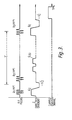
- Figure 3 illustrates the magnetic field sequence employed in the method.
- The method is performed using an apparatus essentially identical to that described in U.K. Patent Specification No. 1,578,910 or No. 2,056,078 to which reference should be made for a fuller description, appropriately programmed to apply a sequence of magnetic field gradient and RF pulses and analyse the resulting signals as hereafter described.
- The essential features of such an apparatus in so far as is required for an understanding of the present invention are as follows:
- The apparatus includes a first coil system whereby a magnetic field can be applied to a body to be examined in a given direction, normally designated the Z-direction, with a gradient in any one or more of the three orthogonal directions i.e. X, Y and Z directions.
- Referring to Figure 1, the first coil system comprises coils 1 capable of providing a steady uniform magnetic field in the Z direction;
coils 3 capable of providing a magnetic field gradient in the X direction,coils 5 capable of providing a magnetic field gradient in the Y direction; and coils 7 capable of providing a magnetic field gradient in the Z direction. - In addition, the apparatus includes a second coil system 9 whereby RF magnetic fields can be applied to the body under examination in a plane normal to the direction of the steady uniform magnetic field produced by the first coil system, and whereby RF magnetic fields resulting from nuclei in the body under examination which have been excited to nuclear magnetic resonance with a spin vector component other than in the Z direction can be detected.
- In the drawing a single pair of coils 9 is shown for both applying and detecting RF fields, but in certain circumstances it may be preferable to provide separate coils for detecting the RF fields.
- The
various coils drive amplifiers control circuits - The
circuits control unit 29 with which are associated inputs andother peripherals 31, for the provision of commands and instructions to the apparatus, and adisplay 33. - The NMR signals detected by the coils 9 are applied via an
amplifier 35 to asignal handling system 37. The signal handling system is arranged to make any appropriate calibration and correction of the signals, but essentially transmits the signals to the processing andcontrol unit 29 wherein the signals are processed for application to the display to produce an image representing the distribution of an NMR quantity in the body being examined. - It will be appreciated that whilst shown separately to clarify the present description, the
signal handling system 37 may conveniently form part of theunit 29. - The apparatus also includes field measurement and
error signal circuits 39 which receive signals viaamplifiers 41 from field probes X1, X2, Y1 and Y2 which are disposed at suitable positions in relation to aslice 43 of the body being examined, as illustrated in Figure 2, to monitor the applied magnetic fields. - Referring now also to Figure 3, in operation of the apparatus a steady uniform magnetic field Bo is applied to the body under examination in the Z direction. This field serves to define the equilibrium axis of magnetic alignment of the nuclei in the body i.e. along the Z direction, and remains constant throughout the examination procedure. A magnetic field gradient Gz along the Z direction is then applied to the body, together with an RF magnetic field pulse denoted B1(900), for reasons explained hereafter. The frequency of the RF field is chosen to be the Larmor frequency for protons in a
slice 43 of the body, normal to the Z direction, the slice being defined by a particular magnetic field along the Z direction, such that protons within the slice are preferentially excited, the slice consisting of an area of substantially solid material through which a series of blood vessels extend. The integral of the RF pulse is such that the pulse is just sufficient to tip the spins of the excited protons into the X-Y plane, and is thus referred to as a 900 pulse, the spins then precessing in the X-Y plane round the Z axis. - The field gradient Gz is then removed, and replaced by a gradient in the opposite sense - Gz . This causes the rephasing of the spins which have been selectively excited by the combination of the RF pulse B1 (90°), Bo and the field gradient Gz, the dephasing having been caused by the gradient through the slice. The magnitude of - Gz is adjusted so that the spins are rephased at the time at which this gradient is switched off as described, for example, in the above mentioned UK Patent Specification No. 1,578,910. Immediately after the - Gz pulse, a second RF magnetic field pulse B2(900) having the same characteristics as the B1(90°) pulse is applied. As it is applied in the absence of any magnetic field gradients it is effective to excite the spins of all the hydrogen protons within the body. Thus the spins within the slice which were already in the X-Y plane are rotated to the -Z direction, whilst the excited spins in the rest of the body are tipped into the X-Y plane.
- A period of time, τ , is then allowed to elapse, during which time the excited spins throughout the body relax back towards.the positive Z direction. During this period a number of pulsed magnetic field gradients Gzd may be imposed along the Z direction, these pulses causing phase dispersion of spins lying in the X-Y plane in addition to the phase dispersion of the spins which naturally occurs, due to spin-spin interaction (T2 effects). The gradients Gzd do not however affect spins in the Z directions. Thus these pulses reduce the signal which would be induced in the second coil system by spins outside the selected slice which have remained in the X-Y plane although for long values of τ this signal would in any case be small.
- After the time period τ has elapsed, a third RF magnetic field pulse B3(90°) again having the same characteristics as the B1 (90°) pulse is applied in the presence of the magnetic field gradient to selectively excite the protons within the slice as before, this sequence again being followed by the rephasing gradient - Gz'. The signal induced in the second coil signal by these spins, i.e. the Free Induction Decay (F.I.D.) system 9 is then recorded, the spins outside the slice which remain in the XY plane after the period having been dephased as explained herebefore, and thus not contributing significantly to the measured signal.
- The magnitude of the measured F.I.D. signal is related to the density of protons within the slice, and will consist of contributions from hydrogen protons in three different circumstances: (1) protons in the solid material in the slice; (2) protons in the blood which has remained in the slice during the period from the B1(900) and B2)900) pulses to the recording of the F.I.D. signal, i.e. a period substantially equal to τ; and (3) hydrogen protons in the 'new' blood which has flowed into the slice during the period.
- Dealing firstly with the protons from the solid material in the slice, a proportion ρOSe-τ/T1S of the spins of the total densityρOS of the hydrogen protons in the solid material will, after the period τ, have remained aligned along the -Z direction, where T1S is the spin-lattice relaxation time for hydrogen protons within the solid material. The remainder of the spins,ρOS (1 - e- τ/T1S) will have relaxed back into their equilibrium alignment along the positive Z direction. After the B3 (90°) pulse, as the spins originating from the positive and negative Z directions respectively are 180° out of phase within the X-Y plane, the net contribution to the measured signal will be ρOS (1-2e-τ/T1S). As in practice the whole pulse sequence is repeated several times, there will be a further contribution to the signal originating from the hydrogen protons in the solid material in the slice of the formρOSe-td/T1S, where td is the time which has passed between the B1 (90°) pulses in each pair of sequences, to compensate for the spins not being in their equilibrium condition i.e. aligned along the positive Z direction, at the beginning of each pulse sequence. Thus the total contribution ρ1 to the measured F.I.D. signal from the solid material in the slice will be of the form:

- Dealing now with the contribution of hydrogen protons in the blood which has remained in the slice during the period τ, a proportion ρOB AvZ of the blood in the slice will have flowed out of the slice during this period, where ρOB is the hydrogen proton density for blood in the slice;
- A is the cross sectional area of the blood vessels through the slice; and
- v is the velocity of the blood through the vessels.
- This, therefore, leaves a proportionρOB (1 - Avτ) of the blood remaining in the slice. An expressionρ2 for the contribution to the measured signal from the blood remaining in the slice can therefore be written:

- Finally, considering the 'new' blood which has flowed into the slice during the time period Cto replace the blood which has flowed out, all the spins which contribute to the measured F.I.D. signal within this blood will have been aligned along the positive Z direction prior to the B3(900) pulse, and thus the contributionl3 from these spins will be of the form:

- It will also be appreciated that whilst the method described hereinbefore relates to determining the rate of flow of a liquid which contains protons, the method is equally applicable to determining the rate of flow of a liquid containing other nuclei having a magnetic spin, e.g. 31p, by appropriate choice of the RF pulse frequency.
Claims (8)
Applications Claiming Priority (2)
| Application Number | Priority Date | Filing Date | Title |
|---|---|---|---|
| GB8223862 | 1982-08-19 | ||
| GB8223862 | 1982-08-19 |
Publications (3)
| Publication Number | Publication Date |
|---|---|
| EP0103388A2 true EP0103388A2 (en) | 1984-03-21 |
| EP0103388A3 EP0103388A3 (en) | 1986-05-14 |
| EP0103388B1 EP0103388B1 (en) | 1988-11-17 |
Family
ID=10532396
Family Applications (1)
| Application Number | Title | Priority Date | Filing Date |
|---|---|---|---|
| EP83304483A Expired EP0103388B1 (en) | 1982-08-19 | 1983-08-03 | Nuclear magnetic resonance methods and apparatus |
Country Status (5)
| Country | Link |
|---|---|
| US (1) | US4587488A (en) |
| EP (1) | EP0103388B1 (en) |
| JP (1) | JPS5960262A (en) |
| DE (1) | DE3378495D1 (en) |
| GB (1) | GB2125562B (en) |
Cited By (4)
| Publication number | Priority date | Publication date | Assignee | Title |
|---|---|---|---|---|
| EP0109238A2 (en) * | 1982-11-10 | 1984-05-23 | Picker International Limited | Nuclear magnetic resonance method and apparatus |
| EP0115642A2 (en) * | 1983-01-04 | 1984-08-15 | Wisconsin Alumni Research Foundation | NMR scanner with motion zeugmatography |
| EP0182481A2 (en) * | 1984-10-22 | 1986-05-28 | The Board Of Trustees Of The Leland Stanford Junior University | A method of, and apparatus for, determining fluid movement using nuclear magnetic resonance |
| EP0215592A2 (en) * | 1985-09-02 | 1987-03-25 | Picker International Limited | Nuclear magnetic resonance imaging methods and apparatus |
Families Citing this family (9)
| Publication number | Priority date | Publication date | Assignee | Title |
|---|---|---|---|---|
| JPS6039539A (en) * | 1983-08-15 | 1985-03-01 | Hitachi Ltd | Inspecting device using nuclear magnetic resonance |
| US4697149A (en) * | 1985-11-04 | 1987-09-29 | Wisconsin Alumni Research Foundation | NMR flow imaging using a composite excitation field and magnetic field gradient sequence |
| IL79076A (en) * | 1986-06-10 | 1989-10-31 | Elscint Ltd | Restricted volume imaging |
| FI874419A (en) * | 1987-10-08 | 1989-04-09 | Instrumentarium Oy | ANORDNING OCH FOERFARANDE FOER UNDERSOEKNING AV ETT OBJEKTS EGENSKAPER. |
| IL84152A (en) * | 1987-10-12 | 1991-06-10 | Elscint Ltd | Magnetic resonance spectroscopic measurements of restricted volumes |
| US6272370B1 (en) | 1998-08-07 | 2001-08-07 | The Regents Of University Of Minnesota | MR-visible medical device for neurological interventions using nonlinear magnetic stereotaxis and a method imaging |
| US6463317B1 (en) | 1998-05-19 | 2002-10-08 | Regents Of The University Of Minnesota | Device and method for the endovascular treatment of aneurysms |
| RU2544360C1 (en) * | 2013-12-04 | 2015-03-20 | Федеральное государственное бюджетное образовательное учреждение высшего профессионального образования "Казанский государственный энергетический университет" (ФГБОУ ВПО "КГЭУ") | Device for measurement of composition and flow rate of multi-component liquids by method of nuclear magnetic resonance |
| CN103969604B (en) * | 2014-05-30 | 2017-03-15 | 华南师范大学 | Radio frequency atomic magnetometer and its method for measurement NMR signal |
Citations (2)
| Publication number | Priority date | Publication date | Assignee | Title |
|---|---|---|---|---|
| US3932805A (en) * | 1973-02-02 | 1976-01-13 | Kichizo Niwa | Method of obtaining internal information of a measuring target from the out-side by the application of a nuclear magnetic resonance phenomenon |
| EP0103372A2 (en) * | 1982-08-11 | 1984-03-21 | Picker International Limited | Nuclear magnetic resonance method and apparatus |
Family Cites Families (4)
| Publication number | Priority date | Publication date | Assignee | Title |
|---|---|---|---|---|
| US4458203A (en) * | 1980-12-11 | 1984-07-03 | Picker International Limited | Nuclear magnetic resonance imaging |
| US4528985A (en) * | 1981-12-21 | 1985-07-16 | Albert Macovski | Blood vessel imaging system using nuclear magnetic resonance |
| US4516075A (en) * | 1983-01-04 | 1985-05-07 | Wisconsin Alumni Research Foundation | NMR scanner with motion zeugmatography |
| US4516582A (en) * | 1983-05-02 | 1985-05-14 | General Electric Company | NMR blood flow imaging |
-
1983
- 1983-08-03 DE DE8383304483T patent/DE3378495D1/en not_active Expired
- 1983-08-03 GB GB08320946A patent/GB2125562B/en not_active Expired
- 1983-08-03 US US06/519,832 patent/US4587488A/en not_active Expired - Fee Related
- 1983-08-03 EP EP83304483A patent/EP0103388B1/en not_active Expired
- 1983-08-19 JP JP58151464A patent/JPS5960262A/en active Pending
Patent Citations (2)
| Publication number | Priority date | Publication date | Assignee | Title |
|---|---|---|---|---|
| US3932805A (en) * | 1973-02-02 | 1976-01-13 | Kichizo Niwa | Method of obtaining internal information of a measuring target from the out-side by the application of a nuclear magnetic resonance phenomenon |
| EP0103372A2 (en) * | 1982-08-11 | 1984-03-21 | Picker International Limited | Nuclear magnetic resonance method and apparatus |
Non-Patent Citations (3)
| Title |
|---|
| IEEE TRANSACTIONS ON MEDICAL IMAGING, vol. MI-1, no. 1, July 1982, pages 42-47, IEEE, New York, US; A. MACOVSKI: "Selective projection imaging: Applications to radiography and NMR" * |
| IEEE TRANSACTIONS ON NUCLEAR SCIENCE, vol. NS-29, no. 3, June 1982, pages 1181-1185, IEEE, New York, US; L. CROOKS et al.: "Quantification of obstructions in vessels by nuclear magnetic resonance (NMR)" * |
| JOURNAL OF CHEMICAL PHYSICS, vol. 56, no. 8, 15th April 1972, pages 3850-3852, New York, US; J.E. TANNER: "Self-diffusion in plastic crystals" * |
Cited By (8)
| Publication number | Priority date | Publication date | Assignee | Title |
|---|---|---|---|---|
| EP0109238A2 (en) * | 1982-11-10 | 1984-05-23 | Picker International Limited | Nuclear magnetic resonance method and apparatus |
| EP0109238A3 (en) * | 1982-11-10 | 1985-05-29 | Picker International Limited | Nuclear magnetic resonance method and apparatus |
| EP0115642A2 (en) * | 1983-01-04 | 1984-08-15 | Wisconsin Alumni Research Foundation | NMR scanner with motion zeugmatography |
| EP0115642A3 (en) * | 1983-01-04 | 1985-06-26 | Wisconsin Alumni Research Foundation | Nmr scanner with motion zeugmatography |
| EP0182481A2 (en) * | 1984-10-22 | 1986-05-28 | The Board Of Trustees Of The Leland Stanford Junior University | A method of, and apparatus for, determining fluid movement using nuclear magnetic resonance |
| EP0182481A3 (en) * | 1984-10-22 | 1986-10-15 | The Board Of Trustees Of The Leland Stanford Junior University | A method of, and apparatus for, determining fluid movement using nuclear magnetic resonance |
| EP0215592A2 (en) * | 1985-09-02 | 1987-03-25 | Picker International Limited | Nuclear magnetic resonance imaging methods and apparatus |
| EP0215592A3 (en) * | 1985-09-02 | 1989-01-25 | Picker International Limited | Nuclear magnetic resonance imaging methods and apparatus |
Also Published As
| Publication number | Publication date |
|---|---|
| GB8320946D0 (en) | 1983-09-07 |
| JPS5960262A (en) | 1984-04-06 |
| DE3378495D1 (en) | 1988-12-22 |
| GB2125562A (en) | 1984-03-07 |
| GB2125562B (en) | 1985-11-20 |
| EP0103388B1 (en) | 1988-11-17 |
| EP0103388A3 (en) | 1986-05-14 |
| US4587488A (en) | 1986-05-06 |
Similar Documents
| Publication | Publication Date | Title |
|---|---|---|
| US4563647A (en) | Nuclear magnetic resonance methods and apparatus | |
| US4520828A (en) | Nuclear magnetic resonance method and apparatus | |
| EP0103388B1 (en) | Nuclear magnetic resonance methods and apparatus | |
| EP0100183B1 (en) | Nuclear magnetic resonance method and apparatus | |
| US4558278A (en) | Nuclear magnetic resonance methods and apparatus | |
| US4733183A (en) | Nuclear magnetic resonance methods and apparatus | |
| US4642568A (en) | Nuclear magnetic resonance methods and apparatus | |
| US4564813A (en) | Nuclear magnetic resonance method and apparatus | |
| US4631480A (en) | Nuclear magnetic resonance method and apparatus | |
| EP0106472B1 (en) | Nuclear magnetic resonance method and apparatus | |
| US4862080A (en) | Method of deriving a spin resonance signal from a moving fluid, and device for performing this method | |
| EP0217578B1 (en) | Nuclear magnetic resonance methods and apparatus | |
| GB2127155A (en) | Flow determination by nuclear magnetic resonance | |
| EP0129356A2 (en) | Nuclear magnetic resonance method and apparatus | |
| US4703269A (en) | Nuclear magnetic resonance imaging methods and apparatus | |
| Burl et al. | Nuclear magnetic resonance method and apparatus |
Legal Events
| Date | Code | Title | Description |
|---|---|---|---|
| PUAI | Public reference made under article 153(3) epc to a published international application that has entered the european phase |
Free format text: ORIGINAL CODE: 0009012 |
|
| AK | Designated contracting states |
Designated state(s): DE FR NL |
|
| PUAL | Search report despatched |
Free format text: ORIGINAL CODE: 0009013 |
|
| AK | Designated contracting states |
Kind code of ref document: A3 Designated state(s): DE FR NL |
|
| 17P | Request for examination filed |
Effective date: 19860616 |
|
| 17Q | First examination report despatched |
Effective date: 19880222 |
|
| GRAA | (expected) grant |
Free format text: ORIGINAL CODE: 0009210 |
|
| AK | Designated contracting states |
Kind code of ref document: B1 Designated state(s): DE FR NL |
|
| REF | Corresponds to: |
Ref document number: 3378495 Country of ref document: DE Date of ref document: 19881222 |
|
| ET | Fr: translation filed | ||
| PLBE | No opposition filed within time limit |
Free format text: ORIGINAL CODE: 0009261 |
|
| STAA | Information on the status of an ep patent application or granted ep patent |
Free format text: STATUS: NO OPPOSITION FILED WITHIN TIME LIMIT |
|
| 26N | No opposition filed | ||
| PGFP | Annual fee paid to national office [announced via postgrant information from national office to epo] |
Ref country code: FR Payment date: 19950717 Year of fee payment: 13 |
|
| PGFP | Annual fee paid to national office [announced via postgrant information from national office to epo] |
Ref country code: NL Payment date: 19950830 Year of fee payment: 13 |
|
| PGFP | Annual fee paid to national office [announced via postgrant information from national office to epo] |
Ref country code: DE Payment date: 19951025 Year of fee payment: 13 |
|
| PG25 | Lapsed in a contracting state [announced via postgrant information from national office to epo] |
Ref country code: NL Effective date: 19970301 |
|
| PG25 | Lapsed in a contracting state [announced via postgrant information from national office to epo] |
Ref country code: FR Effective date: 19970430 |
|
| NLV4 | Nl: lapsed or anulled due to non-payment of the annual fee |
Effective date: 19970301 |
|
| PG25 | Lapsed in a contracting state [announced via postgrant information from national office to epo] |
Ref country code: DE Effective date: 19970501 |
|
| REG | Reference to a national code |
Ref country code: FR Ref legal event code: ST |