EP0104772B1 - Calibrated optical oximeter probe - Google Patents
Calibrated optical oximeter probe Download PDFInfo
- Publication number
- EP0104772B1 EP0104772B1 EP83304940A EP83304940A EP0104772B1 EP 0104772 B1 EP0104772 B1 EP 0104772B1 EP 83304940 A EP83304940 A EP 83304940A EP 83304940 A EP83304940 A EP 83304940A EP 0104772 B1 EP0104772 B1 EP 0104772B1
- Authority
- EP
- European Patent Office
- Prior art keywords
- probe
- oximeter
- light
- light emitting
- known wavelength
- Prior art date
- Legal status (The legal status is an assumption and is not a legal conclusion. Google has not performed a legal analysis and makes no representation as to the accuracy of the status listed.)
- Expired - Lifetime
Links
Images
Classifications
-
- A—HUMAN NECESSITIES
- A61—MEDICAL OR VETERINARY SCIENCE; HYGIENE
- A61B—DIAGNOSIS; SURGERY; IDENTIFICATION
- A61B5/00—Measuring for diagnostic purposes; Identification of persons
- A61B5/145—Measuring characteristics of blood in vivo, e.g. gas concentration, pH value; Measuring characteristics of body fluids or tissues, e.g. interstitial fluid, cerebral tissue
- A61B5/1455—Measuring characteristics of blood in vivo, e.g. gas concentration, pH value; Measuring characteristics of body fluids or tissues, e.g. interstitial fluid, cerebral tissue using optical sensors, e.g. spectral photometrical oximeters
- A61B5/14551—Measuring characteristics of blood in vivo, e.g. gas concentration, pH value; Measuring characteristics of body fluids or tissues, e.g. interstitial fluid, cerebral tissue using optical sensors, e.g. spectral photometrical oximeters for measuring blood gases
- A61B5/14552—Details of sensors specially adapted therefor
-
- A—HUMAN NECESSITIES
- A61—MEDICAL OR VETERINARY SCIENCE; HYGIENE
- A61B—DIAGNOSIS; SURGERY; IDENTIFICATION
- A61B5/00—Measuring for diagnostic purposes; Identification of persons
- A61B5/145—Measuring characteristics of blood in vivo, e.g. gas concentration, pH value; Measuring characteristics of body fluids or tissues, e.g. interstitial fluid, cerebral tissue
- A61B5/1495—Calibrating or testing of in-vivo probes
-
- G—PHYSICS
- G01—MEASURING; TESTING
- G01N—INVESTIGATING OR ANALYSING MATERIALS BY DETERMINING THEIR CHEMICAL OR PHYSICAL PROPERTIES
- G01N21/00—Investigating or analysing materials by the use of optical means, i.e. using sub-millimetre waves, infrared, visible or ultraviolet light
- G01N21/17—Systems in which incident light is modified in accordance with the properties of the material investigated
- G01N21/25—Colour; Spectral properties, i.e. comparison of effect of material on the light at two or more different wavelengths or wavelength bands
- G01N21/31—Investigating relative effect of material at wavelengths characteristic of specific elements or molecules, e.g. atomic absorption spectrometry
- G01N21/314—Investigating relative effect of material at wavelengths characteristic of specific elements or molecules, e.g. atomic absorption spectrometry with comparison of measurements at specific and non-specific wavelengths
- G01N21/3151—Investigating relative effect of material at wavelengths characteristic of specific elements or molecules, e.g. atomic absorption spectrometry with comparison of measurements at specific and non-specific wavelengths using two sources of radiation of different wavelengths
-
- A—HUMAN NECESSITIES
- A61—MEDICAL OR VETERINARY SCIENCE; HYGIENE
- A61B—DIAGNOSIS; SURGERY; IDENTIFICATION
- A61B2562/00—Details of sensors; Constructional details of sensor housings or probes; Accessories for sensors
- A61B2562/08—Sensors provided with means for identification, e.g. barcodes or memory chips
-
- G—PHYSICS
- G01—MEASURING; TESTING
- G01N—INVESTIGATING OR ANALYSING MATERIALS BY DETERMINING THEIR CHEMICAL OR PHYSICAL PROPERTIES
- G01N35/00—Automatic analysis not limited to methods or materials provided for in any single one of groups G01N1/00 - G01N33/00; Handling materials therefor
- G01N35/00584—Control arrangements for automatic analysers
- G01N35/00722—Communications; Identification
- G01N35/00732—Identification of carriers, materials or components in automatic analysers
Definitions
- This invention relates to a probe for an oximeter monitor and oximeter for the determination of arterial oxygen saturation and/or pulse rate in a patient.
- U.S. Patent No. 2,706,927 to Wood disclosed the computation of oxygen saturation from measurements of light absorption of body tissue at two wavelengths. A series of devices and procedures have been founded using this technology.
- a required peripheral device of such photoelectric oximeters is a photoelectric probe.
- a photoelectric probe is clamped to an appendage of a patient's body, such as an ear or a finger.
- Such probes require at least one light source for directing light into the appendage and at least one sensor for receiving light diffused out of the appendage.
- One method of obtaining light of the desired frequency has been to use a light surce of indeterminate wavelength range in combination with a monochromatic filter of known output. Such devices are inefficient, and result in unwanted power demands and heat generation.
- Re-calibration perhaps necessitating return of the oximeters to the factory, can become necessary even for prior art devices when, for example, a probe is broken.
- a supply of light sources having consistently identical wavelengths is required.
- light emitting diodes are known to vary in wavelengths from unit-to-unit.
- An advantage of the embodiment of the present invention is that the apparatus is inexpensive, replaceable, easily applied and overcomes the disadvantages and limitations of the prior art as detailed above.
- the embodiment has a probe whose wavelength emission characteristics are readily ascertainable by the attendant oximeter.
- This embodiment enables factory calibration of LEDs for use in such a probe.
- LEDs are purchased in batches of one general wavelength, but whose exact wavelength characteristics are unknown and vary from piece to piece.
- Yet another feature of this embodiment is that it provides flexible attachment means for the probe which will allow rapid attachment to human or animal appendages of varying sizes yet maintain the photoelectric sensor in direct optical isolation from the LEDs.
- Yet another feature of this embodiment is that it has a multiconductor plug with wiring in a binary array to transmit probe calibration.
- the invention provides an oximeter system comprising the above-mentioned probe and an oximeter; this system is characterized by decoding means responsive to said encoded signals for selecting appropriate calibration coefficients for use in calculating oxygen saturation based upon the known wavelength of said first and/or second light emitting means.
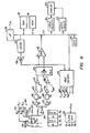
- Conventional microprocessor 116 has a bus 117 extending therefrom.
- Bus 117 has connected thereto conventional ROM 118 and RAM 119.
- An LED display 120 is schematically illustrated having a select latch 121 and a digit designation latch 122.
- Finger 114 of a patient is illustrated with probe 101 having schematic detection circuitry.
- First light emitting diode 132 in the red range and a second light emitting diode 130 in the infrared range are sequentially pulsed to emit light in their respective frequencies by amplifiers 131, 133.
- LED 132 is in the 6600 angstrom range (660 nm) with LED 130 being in the 9400 angstrom range (940 nm).
- a light impervious barrier 136 is placed between photosensor 138 and finger 114. Barrier 136, terminating in contact with the flesh of finger 114, makes the path between the respective light emitting diodes 130, 132 and the light receiving diode 138 occur only through the flesh of finger 114.
- Signal received from the respective light emitting diodes first passes through a pre-amplifier 140. This signal is thereafter amplified in parallel at amplifiers 141, 142. As amplified, the signal is passed in parallel from each amplifier through respective phase detectors 143, 144. Passage through respective low pass filters 145,146 thereafter occurs. Amplification at offset amplifiers 147, 148 then takes place. The pulsatile component is passed to multiplexer 150.
- Multiplexer 150 has output to a comparator 152.
- Comparator 152 is ramped in half steps by a 12 bit digital to analog converter (hereinafter DAC) 154.
- DAC 154 places a comparison signal divided in one part from 4096 parts with the comparator outputting to bus 117.
- microprocessor 116 is programmed to receive signal from photosensor 138 within an optimum range. Utilizing a second operating phase of DAC 154, and communicating signal to a sample hold 157, the individual LED's 130,132 are given voltage outputs 160, 161. These voltage outputs 160, 161 are adjusted so that in each case photosensor 138 looks at a signal well within the range of the DAC.
- Clock 170 controls the sequential output of light from the light emitting diodes 130, 132 to a duty cycle of at least 1 in 4. This is schematically illustrated by signals ⁇ 1 through ⁇ 4. Reception of signal at detector 143 occurs during time periods ⁇ 1 and ⁇ 2 and reception of signal occurs at detector 144 during time periods ⁇ 3 and (p4.
- FIG. 6 is a copy of Fig. 2 from European patent application No. 83304938 having been renumbered to avoid confusion with the context herewith.
- the above application is concerned with a pulse oximeter of the type wherein light of two different wavelengths is passed through human or animal body tissue, such as a finger, an ear, the nasal septum or the scalp, so as to be modulated by the pulsatile component of arterial blood therein, and thereby allowing indication of oxygen saturation, blood perfusion and heart rate.
- the level of incident light is continually adjusted for optimal detection of the pulsatile component, while permitting accommodation to variable attenuations due to skin color, flesh thickness and other invariants.
- a quotient of the pulsatile component of light transmission over the constant component of light transmission is measured for each of two wavelengths by direct digital tracking. The respective quotients are thereafter converted to a ratio, which ratio may be thereafter fitted to a curve of independently derived of oxygen saturation.
- Calibration is disclosed by solving four unknowns at at least four differing saturations. An output of pulse rate, pulsatile flow and oxygen saturation is given. An incident light source duty cycle is chosen to be at least 1 in 4 so that noise, inevitably present in the signal, may be substantially eliminated and filtered.
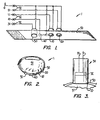
- FIG. 1 of the present application a part-schematic, part-perspective view of the optical probe 1 is shown.
- a suitable length of adjustable, self-fastening tape 50 is provided, such as that sold under the trade mark VELCRO, obtainable from American Velcro, Inc. Incorporated into tape 50 at suitably spaced intervals are the electrical components of probe 1.
- Photoelectric sensor 30 is attached to the outside of tape 50 and protrudes slightly from the underside of tape 50.
- Sensor 30 has ground wire G and lead wire 31.
- Light emitting diode 10 typically emitting frequencies in the infrared range of the spectrum, is mounted to and pierces tape 50 in a similar manner to sensor 30 and at a distance from sensor 30 selected upon the basis of the typical appendage size expected to be encountered.
- LED 10 is connected to ground wire G and has input lead wire 11.
- a second LED 20 typically having wavelength emission characterisics in the red range of the spectrum.
- LED 20 attaches to ground wire G and has input lead wire 21.
- Resistor 40 is shown mounted to tape 50 between sensor 30 and LED 10. However, the physical location of resistor 40 is not important and it may be mounted to probe 1 at any other convenient location. Resistor 40 has input lead wire 41 and is connected to ground wire G.
- Wires G, 11, 21, 31, 41 lead to connector 52 so that probe 11 may be readily disconnected from the oximeter 60 (schematically illustrated in Fig. 4).
- the probe 1 illustrated in Fig. 1 is designed for use in connection with an oximeter 60 designed to operate in conjunction with two LEDs 10, 20 sequentially transmitting light to a single sensor 30.
- the mechanism of the instant invention works equally well for oximeters requiring only a single LED and single or multiple photo sensors. Oximeters requiring more than two LEDs may be equally well accommodated by the probe of the present invention.
- Fig. is an end elevation of a typical finger 51 of a human patient. Finger 51 is encircled by probe 1 at its tip by overlapping the ends of self-connecting tape 50. Light emitted from LEDs 10, 20 enter the flesh offinger 51 and are subjected to diffusion and scattering. Sensor 30 picks up only light which has been diffused through the flesh of finger 51.
- Fig. 3 is a detailed side elevation of sensor 30, showing the manner in which it is assured that no light emitted by LEDs 10,20 is received by sensor 30 without first passing through finger 51.
- Sensor element 32 is recessed somewhat within metal cylinder wall 33 of the sensor housing. Since tape 50 presses sensor 30 directly against the skin of finger 51, it is readily seen that no light passes to sensor element 32 other than through the flesh of finger 51.
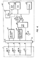
- Probe 1 is constructed in the following manner: LED's 10, 20 are selected from batches of LED's with generally known wavelength characteristics. The exact wavelength characteristics of the specific LED's 10,20 chosen are determined at this time through readily available metering means. Resistor 40 is then selected to have a resistance whose amount is exactly specified by a table made available to the factory technician forthis purpose, of all possible wavelength combinations which may be expected to be encountered from the available supplies of LEDs. The following table is an example of how a single resistor 40 might be selected for any hypothetical combination of LED's 10,20 in a case where each has only two possible wavelengths:
- a typical probe will have an infrared LED 10 of wavelength 940 nanometers and a red LED 20 of wavelength 660 nanometers. According to the above table, a probe having such wavelength characteristics will be supplied atthe factory with a resistor 40 of one, and only one, resistance value, in this case shown to be 150 ohms.
- Oximeter 60 contains a microprocessor 61, and a read only memory 62 and random access memory 63.
- Table A (the same table used for calibrating probe 1 at the factory) no matter how extensive, may be easily programmed into ROM 62 at the time oximeter 60 is fabricated.
- Current I from current source 69 is passed through resistor 40.
- the resulting voltage (per Ohm's law) is passed through multiplexer 66 through comparator 65, to microprocessor 61.
- Microprocessor 61 may be programmed to calculate the resistance of resistor 40 and thereafter to look up the wavelengths of LED's 10, 20 from Table A in ROM 62. Microprocessor 61 is also programmed to itself recalibrate the optical comparison circuitry of oximeter 60 once the wavelengths of LEDs 10, 20 are known. By this means, it is not required to recalibrate by hand oximeter 60 for each new probe 1 nor, alternatively, to require that LEDs 10, 20 be of precisely standardized wavelengths.
- circuitry schematically illustrated in Fig. 4 The specific function and design of the circuitry schematically illustrated in Fig. 4 is seen as obvious when taken in combination with the general description of its function.
- the functions of microprocessors and read only memories are well known and understood and it is well within the capability of a person with ordinary skill in the art to design and program microprocessor 61 to calculate the resistance of resistor 40 and thereby obtain the wavelengths of LEDs 10, 20 from a simple lookup table in a ROM 62.
- Probe 1 may be used with any number of prior art oximeters, the method of operation of which is well understood and beyond the scope of the teaching of the present invention.
- fresh blood is pumped into the capillaries of finger 51, thereby causing a periodic increase and decrease in reflected light intensity observed by sensor 30.
- the oxygen saturation of hemoglobin in the pulsalite blood may be determined by the oximeter 60.
- there is a known extinction coefficient B Given B and measuring the intensity of diffused light received by sensor 30 the oxygen saturation can be computed and displayed.
- the coefficients B ofthe various wavelengths oftable A can be substituted for the wavelengths directly when the table is programmed into ROM 62, thereby eliminating a computational step.
- Microprocessor 61 through LED control circuitry67, operates LEDs 10,20. Lightfrom LEDs 10, 20 results in current in sensor 30 which passes through amplification and filtration circuitry 68 to multiplexer 66. Comparator 65, in combination with a digital to analog converter 70 allows microprocessors 61 to determine oxygen saturation and/or pulse rate. Results are shown on display 64.
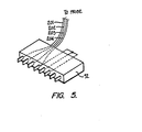
- an alternate way of coding a probe of this invention is illustrated.
- an eight bit connector 52' similar to the connector 52 is illustrating having respective connectors 201, 202,203 respectively communicating to light emitting diode 130, light emitting diode 132 and photodetector 138.
- Conductor 204 is illustrated providing the ground connection.
- the eight bit connector has four empty channels. These channels can be provided to communicate the coded value of the probe.
- the connectors when provided with a common potential provide a positive binary value and when independent of any potential provide a negative value.
- the four conductors of plug 52, as illustrated in Fig. 5 would communicate the binary value 1100.
- communication of the resistance value of the connected probe would be possible by coding the connector to a value of 1 part in 16.
Abstract
Description
- This invention relates to a probe for an oximeter monitor and oximeter for the determination of arterial oxygen saturation and/or pulse rate in a patient.
- A serious problem exists in operating rooms. Specifically, the chemical determination of oxygen level in blood consumes at least 3 to 5 minutes. A patient deprived of blood oxygen for such a duration typically incurs irreversible brain damage if not death.
- U.S. Patent No. 2,706,927 to Wood disclosed the computation of oxygen saturation from measurements of light absorption of body tissue at two wavelengths. A series of devices and procedures have been founded using this technology.
- A required peripheral device of such photoelectric oximeters is a photoelectric probe. Typically, such a probe is clamped to an appendage of a patient's body, such as an ear or a finger. Such probes require at least one light source for directing light into the appendage and at least one sensor for receiving light diffused out of the appendage. One method of obtaining light of the desired frequency has been to use a light surce of indeterminate wavelength range in combination with a monochromatic filter of known output. Such devices are inefficient, and result in unwanted power demands and heat generation.
- U.S. Patent No. 3,704,706 to Herczfeld et al disclosed the use of a solid state red laser in an optical probe with a solid state photodetector. Although lasers are useful for emitting monochromatic light of known wavelength, thereby eliminating need for a filter, they remain expensive and unwieldy.
- U.S. Patent No. 3,847,483 to Shaw et al. disclosed the use of light emitting diodes to provide the necessary monochromatic light. The probe of Shaw required expensive fiber optic cables.
- A problem with all prior art devices is that they are too expensive to be readily disposable. The need for a truely disposable probe is great, given the many surgical applications in which sterility must be assured. The prior art optical probes, being more or less permanent portions of their respective oximeters, were subjected to a one time determination of the wavelength of the light sources therein and the oximetre was then programmed or adjusted to process light of the known wavelength.
- A problem in developing disposable probes, therefore, has been the necessity to avoid having to reprogram or adjust the oximeter for each new probe or alternately to maintain probes within narrow limits of wavelength variation, a clearly impractical task.
- Re-calibration, perhaps necessitating return of the oximeters to the factory, can become necessary even for prior art devices when, for example, a probe is broken. Alternatively, a supply of light sources having consistently identical wavelengths is required. In particular, light emitting diodes are known to vary in wavelengths from unit-to-unit.
- Other optical probes are shown in patents to Shaw, U.S. Patent No. 3,638,640, Neilsen, U.S. Patent No. 4,167,331, and Konishi, U.S. Patent No. 3,998,550.
- According to the invention, an oximeter probe for use with an oximeter is provided; said probe comprises a first light emitting means emitting light having a first known wavelength value; means for sensing the light emitted by said first light emitting means; means for detachably wiring the probe to the oximeter and for providing communication of electrical signals between the probe and the oximeter; and encoding means for providing signals to the oximeter which are indicative of the known wavelength value of said first light emitting means.
- An advantage of the embodiment of the present invention is that the apparatus is inexpensive, replaceable, easily applied and overcomes the disadvantages and limitations of the prior art as detailed above.
- The embodiment has a probe whose wavelength emission characteristics are readily ascertainable by the attendant oximeter.
- This embodiment enables factory calibration of LEDs for use in such a probe. Typically, LEDs are purchased in batches of one general wavelength, but whose exact wavelength characteristics are unknown and vary from piece to piece.
- It is a further feature of this embodiment that it eliminates the necessity for oximeters to be calibrated for new probes, other than the initial factory calibration.
- Yet another feature of this embodiment isthat it provides flexible attachment means for the probe which will allow rapid attachment to human or animal appendages of varying sizes yet maintain the photoelectric sensor in direct optical isolation from the LEDs.
- Yet another feature of this embodiment is that it has a multiconductor plug with wiring in a binary array to transmit probe calibration.
- Furthermore the invention provides an oximeter system comprising the above-mentioned probe and an oximeter; this system is characterized by decoding means responsive to said encoded signals for selecting appropriate calibration coefficients for use in calculating oxygen saturation based upon the known wavelength of said first and/or second light emitting means.
- Embodiments of the present invention will now be described by way of example with reference to the accompanying drawings in which:-
- Fig. 1 is a part perspective, part schematic diagram of the optical probe of the preferred embodiment of the present invention.
- Fig. 2 is an end view of a patient's finger showing implacement of the probe of the present invention.
- Fig. 3 is a side elevation of an embodiment of a photoelectric sensor of the probe of Fig. 2.
- Fig. 4 is a simplified schematic circuit diagram illustrating the method in which an oximeter microprocessor decodes the wavelength values of the probe through use of a coded resistor.
- Fig. 5 is a schematic of the probe of this invention calibrated by a multiconductor plug and wired in a binary array and
- Fig. 6 is a circuit schematic of an oximeter utilizing a calibrated probe of this invention.
- Conventional microprocessor 116 has a
bus 117 extending therefrom.Bus 117 has connected thereto conventional ROM 118 and RAM 119. An LED display 120 is schematically illustrated having a select latch 121 and adigit designation latch 122. - Having set forth the more or less conventional portions of the microprocessor, attention will now be directed to the analog portions of the circuitry.
-
Finger 114 of a patient is illustrated with probe 101 having schematic detection circuitry. First light emitting diode 132 in the red range and a secondlight emitting diode 130 in the infrared range are sequentially pulsed to emit light in their respective frequencies by amplifiers 131, 133. Typically, LED 132 is in the 6600 angstrom range (660 nm) withLED 130 being in the 9400 angstrom range (940 nm). - It is necessary that all the light from the active light emitting diode go through the flesh in
finger 114. Therefore, a lightimpervious barrier 136 is placed between photosensor 138 andfinger 114.Barrier 136, terminating in contact with the flesh offinger 114, makes the path between the respectivelight emitting diodes 130, 132 and the light receiving diode 138 occur only through the flesh offinger 114. - Signal received from the respective light emitting diodes first passes through a pre-amplifier 140. This signal is thereafter amplified in parallel at
amplifiers 141, 142. As amplified, the signal is passed in parallel from each amplifier throughrespective phase detectors 143, 144. Passage through respective low pass filters 145,146 thereafter occurs. Amplification atoffset amplifiers 147, 148 then takes place. The pulsatile component is passed tomultiplexer 150. -
Multiplexer 150 has output to acomparator 152.Comparator 152 is ramped in half steps by a 12 bit digital to analog converter (hereinafter DAC) 154.DAC 154 places a comparison signal divided in one part from 4096 parts with the comparator outputting tobus 117. - The reader will recognize that not all human fingers and appendages are the same. Specifically, the difference between the races, skin pigment, weight, age, maturity and other factors all can lead to different signals being sensed at photosensor 138, even though the frequency and intensity of the light signal output at each of the
diodes 130, 132 is the same. - Accordingly, microprocessor 116 is programmed to receive signal from photosensor 138 within an optimum range. Utilizing a second operating phase of
DAC 154, and communicating signal to a sample hold 157, the individual LED's 130,132 are givenvoltage outputs -
Clock 170 controls the sequential output of light from thelight emitting diodes 130, 132 to a duty cycle of at least 1 in 4. This is schematically illustrated by signals ϕ1 through ϕ4. Reception of signal atdetector 143 occurs during time periods ϕ1 and ϕ2 and reception of signal occurs at detector 144 during time periods ϕ3 and (p4. - It can be immediately realized that during respective time periods ϕ1, ϕ3 active signal from the
light emitting diodes 130, 132 is being received. During the time periods ϕ2 and ϕ4, no signal and only noise is being received. As will hereinafter become apparent, by amplifying the negative signal before passage through the low pass filter, noise can be subtracted out utilizing the illustrated 1 in 4 duty cycle. - Figure 6 is a copy of Fig. 2 from European patent application No. 83304938 having been renumbered to avoid confusion with the context herewith. The above application is concerned with a pulse oximeter of the type wherein light of two different wavelengths is passed through human or animal body tissue, such as a finger, an ear, the nasal septum or the scalp, so as to be modulated by the pulsatile component of arterial blood therein, and thereby allowing indication of oxygen saturation, blood perfusion and heart rate. The level of incident light is continually adjusted for optimal detection of the pulsatile component, while permitting accommodation to variable attenuations due to skin color, flesh thickness and other invariants. At significant slope reversal of the pulsatile component to negative (indicating a wave maximum), wave form analysis of blood flow occurs. A quotient of the pulsatile component of light transmission over the constant component of light transmission is measured for each of two wavelengths by direct digital tracking. The respective quotients are thereafter converted to a ratio, which ratio may be thereafter fitted to a curve of independently derived of oxygen saturation. Calibration is disclosed by solving four unknowns at at least four differing saturations. An output of pulse rate, pulsatile flow and oxygen saturation is given. An incident light source duty cycle is chosen to be at least 1 in 4 so that noise, inevitably present in the signal, may be substantially eliminated and filtered.
- Referring to Fig. 1 of the present application, a part-schematic, part-perspective view of the
optical probe 1 is shown. A suitable length of adjustable, self-fasteningtape 50 is provided, such as that sold under the trade mark VELCRO, obtainable from American Velcro, Inc. Incorporated intotape 50 at suitably spaced intervals are the electrical components ofprobe 1.Photoelectric sensor 30 is attached to the outside oftape 50 and protrudes slightly from the underside oftape 50. -
Sensor 30 has ground wire G and lead wire 31.Light emitting diode 10, typically emitting frequencies in the infrared range of the spectrum, is mounted to and piercestape 50 in a similar manner tosensor 30 and at a distance fromsensor 30 selected upon the basis of the typical appendage size expected to be encountered.LED 10 is connected to ground wire G and hasinput lead wire 11. Placed in proximity toLED 10 is asecond LED 20, typically having wavelength emission characterisics in the red range of the spectrum.LED 20 attaches to ground wire G and hasinput lead wire 21. -
Resistor 40 is shown mounted totape 50 betweensensor 30 andLED 10. However, the physical location ofresistor 40 is not important and it may be mounted to probe 1 at any other convenient location.Resistor 40 hasinput lead wire 41 and is connected to ground wire G. - Wires G, 11, 21, 31, 41 lead to
connector 52 so thatprobe 11 may be readily disconnected from the oximeter 60 (schematically illustrated in Fig. 4). - The
probe 1 illustrated in Fig. 1 is designed for use in connection with anoximeter 60 designed to operate in conjunction with twoLEDs single sensor 30. However, the mechanism of the instant invention works equally well for oximeters requiring only a single LED and single or multiple photo sensors. Oximeters requiring more than two LEDs may be equally well accommodated by the probe of the present invention. - Fig. is an end elevation of a
typical finger 51 of a human patient.Finger 51 is encircled byprobe 1 at its tip by overlapping the ends of self-connectingtape 50. Light emitted fromLEDs flesh offinger 51 and are subjected to diffusion and scattering.Sensor 30 picks up only light which has been diffused through the flesh offinger 51. - Fig. 3 is a detailed side elevation of
sensor 30, showing the manner in which it is assured that no light emitted byLEDs sensor 30 without first passing throughfinger 51. Sensor element 32 is recessed somewhat within metal cylinder wall 33 of the sensor housing. Sincetape 50presses sensor 30 directly against the skin offinger 51, it is readily seen that no light passes to sensor element 32 other than through the flesh offinger 51. -
Probe 1 is constructed in the following manner: LED's 10, 20 are selected from batches of LED's with generally known wavelength characteristics. The exact wavelength characteristics of the specific LED's 10,20 chosen are determined at this time through readily available metering means.Resistor 40 is then selected to have a resistance whose amount is exactly specified by a table made available to the factory technician forthis purpose, of all possible wavelength combinations which may be expected to be encountered from the available supplies of LEDs. The following table is an example of how asingle resistor 40 might be selected for any hypothetical combination of LED's 10,20 in a case where each has only two possible wavelengths:
- A typical probe will have an
infrared LED 10 of wavelength 940 nanometers and ared LED 20 of wavelength 660 nanometers. According to the above table, a probe having such wavelength characteristics will be supplied atthe factory with aresistor 40 of one, and only one, resistance value, in this case shown to be 150 ohms. - The value in having such a unique known resistance incorporated into
probe 1 is shown by reference to Fig. 4.Oximeter 60 contains amicroprocessor 61, and a read onlymemory 62 and random access memory 63. Table A (the same table used for calibratingprobe 1 at the factory) no matter how extensive, may be easily programmed intoROM 62 at thetime oximeter 60 is fabricated. Current I fromcurrent source 69 is passed throughresistor 40. The resulting voltage (per Ohm's law) is passed throughmultiplexer 66 throughcomparator 65, tomicroprocessor 61. -
Microprocessor 61 may be programmed to calculate the resistance ofresistor 40 and thereafter to look up the wavelengths of LED's 10, 20 from Table A inROM 62.Microprocessor 61 is also programmed to itself recalibrate the optical comparison circuitry ofoximeter 60 once the wavelengths ofLEDs hand oximeter 60 for eachnew probe 1 nor, alternatively, to require thatLEDs - The specific function and design of the circuitry schematically illustrated in Fig. 4 is seen as obvious when taken in combination with the general description of its function. The functions of microprocessors and read only memories are well known and understood and it is well within the capability of a person with ordinary skill in the art to design and
program microprocessor 61 to calculate the resistance ofresistor 40 and thereby obtain the wavelengths ofLEDs ROM 62. -
Probe 1 may be used with any number of prior art oximeters, the method of operation of which is well understood and beyond the scope of the teaching of the present invention. Basically, for each heart beat, fresh blood is pumped into the capillaries offinger 51, thereby causing a periodic increase and decrease in reflected light intensity observed bysensor 30. The oxygen saturation of hemoglobin in the pulsalite blood may be determined by theoximeter 60. For any known wavelength, there is a known extinction coefficient B. Given B and measuring the intensity of diffused light received bysensor 30 the oxygen saturation can be computed and displayed. In fact, the coefficients B ofthe various wavelengths oftable A can be substituted for the wavelengths directly when the table is programmed intoROM 62, thereby eliminating a computational step. -
Microprocessor 61, through LED control circuitry67, operatesLEDs Lightfrom LEDs sensor 30 which passes through amplification andfiltration circuitry 68 tomultiplexer 66.Comparator 65, in combination with a digital toanalog converter 70 allowsmicroprocessors 61 to determine oxygen saturation and/or pulse rate. Results are shown on display 64. - Referring to Fig. 5, an alternate way of coding a probe of this invention is illustrated. Specifically, an eight bit connector 52' similar to the
connector 52 is illustrating havingrespective connectors 201, 202,203 respectively communicating to light emittingdiode 130, light emitting diode 132 and photodetector 138. Conductor 204 is illustrated providing the ground connection. - It will be noted that the eight bit connector has four empty channels. These channels can be provided to communicate the coded value of the probe.
- For example, assuming that the connectors when provided with a common potential provide a positive binary value and when independent of any potential provide a negative value. Thus, the four conductors of
plug 52, as illustrated in Fig. 5, would communicate the binary value 1100. Thus, communication of the resistance value of the connected probe would be possible by coding the connector to a value of 1 part in 16. - Those skilled in the art will appreciate that other binary connections could as well be made. For example, by expanding the number of connectors on the probe relatively large expansions can occur.
- Those skilled in the art will realize that in determining the variable transmission of light in human flesh the frequency at which the flesh is integrated by a substantially monochromatic light source is critical. If the frequency varies the results of the instrument can be inaccurate with such variation. Simply stated, at different points in the spectral frequency, oxygenated hemoglobin and reduced hemoglobin transmit varying amounts of light.
- Commercially produced light emitting diodes do have variation in their spectral frequency from diode to diode. Therefore if such commercially produced diodes are going to be used as replaceable probes in an instrument it has been found that provision must be made for a probe by probe calibration of the instrument. Thus, effectively disposable probes can be readily used even though they are affecting integration at differing frequencies from probe to probe.
- Some comment can be made directed specifically at calibrating the disposable probe of the instrument herein. As a practical matter, the blood of a human is interrogated through the skin by light transmission utilizing red and infrared. The rate of change of constants in the infrared is relatively flat. Therefore a variance in the frequency of the infrared diode has little effect.
- Not so in the red range. It has been found thatthe attenuation of light in oxygenated and unoxyge- nated hemoglobin has a rapidly changing slope in the red range. This being the case, it is of primary concern to calibrate in the particular instrument illustrated in the red range.
- Those skilled in the art will realized thatthere are many ways in which change of instrument calibration can occur. Specifically, separate look-up tables can be generated for various grouped relationships. Alternately, and perhaps more productively, incremental alternation to the constants of curvature between the saturation level S and the ratio of quotients R of light transmission can be determined.
- Although theforegoing invention is described in some detail by way of illustration and example for purpose of clarity of understanding, it is understood that certain changes and modifications may be practiced and equivalents employed within the scope of the appended claims. For example, two resistors may be used in place of one, each resistor coded to the wavelength of a separate LED. Other components could be used in place of resistors, e.g., capacitors or the like. Therefore, the above description and illustrations should not be construed as limiting the scope of the invention which is defined by the appended claims.
Referring to Fig. 6, the pulse oximeter of this invention is illustrated.
Claims (8)
Priority Applications (1)
| Application Number | Priority Date | Filing Date | Title |
|---|---|---|---|
| AT83304940T ATE51134T1 (en) | 1982-09-02 | 1983-08-25 | CALIBRATED OPTICAL OXYMETRY PROBE. |
Applications Claiming Priority (2)
| Application Number | Priority Date | Filing Date | Title |
|---|---|---|---|
| US41417682A | 1982-09-02 | 1982-09-02 | |
| US414176 | 1982-09-02 |
Related Child Applications (1)
| Application Number | Title | Priority Date | Filing Date |
|---|---|---|---|
| EP89105503.0 Division-Into | 1989-03-29 |
Publications (3)
| Publication Number | Publication Date |
|---|---|
| EP0104772A2 EP0104772A2 (en) | 1984-04-04 |
| EP0104772A3 EP0104772A3 (en) | 1985-10-23 |
| EP0104772B1 true EP0104772B1 (en) | 1990-03-21 |
Family
ID=23640289
Family Applications (1)
| Application Number | Title | Priority Date | Filing Date |
|---|---|---|---|
| EP83304940A Expired - Lifetime EP0104772B1 (en) | 1982-09-02 | 1983-08-25 | Calibrated optical oximeter probe |
Country Status (5)
| Country | Link |
|---|---|
| EP (1) | EP0104772B1 (en) |
| JP (2) | JPS5964031A (en) |
| AT (1) | ATE51134T1 (en) |
| DE (2) | DE3381344D1 (en) |
| HK (1) | HK161195A (en) |
Cited By (10)
| Publication number | Priority date | Publication date | Assignee | Title |
|---|---|---|---|---|
| US6725072B2 (en) | 1990-10-06 | 2004-04-20 | Hema Metrics, Inc. | Sensor for transcutaneous measurement of vascular access blood flow |
| US6746407B2 (en) | 2000-12-29 | 2004-06-08 | Hema Metrics, Inc. | Method of measuring transcutaneous access blood flow |
| US6804543B2 (en) | 1998-02-05 | 2004-10-12 | Hema Metrics, Inc. | Sensor for transcutaneous measurement of vascular access blood flow |
| US7990382B2 (en) | 2006-01-03 | 2011-08-02 | Masimo Corporation | Virtual display |
| USRE44823E1 (en) | 1998-10-15 | 2014-04-01 | Masimo Corporation | Universal modular pulse oximeter probe for use with reusable and disposable patient attachment devices |
| US8706179B2 (en) | 1998-10-15 | 2014-04-22 | Masimo Corporation | Reusable pulse oximeter probe and disposable bandage apparatii |
| US8920317B2 (en) | 2003-07-25 | 2014-12-30 | Masimo Corporation | Multipurpose sensor port |
| US9560998B2 (en) | 2006-10-12 | 2017-02-07 | Masimo Corporation | System and method for monitoring the life of a physiological sensor |
| US9795739B2 (en) | 2009-05-20 | 2017-10-24 | Masimo Corporation | Hemoglobin display and patient treatment |
| US10188348B2 (en) | 2006-06-05 | 2019-01-29 | Masimo Corporation | Parameter upgrade system |
Families Citing this family (40)
| Publication number | Priority date | Publication date | Assignee | Title |
|---|---|---|---|---|
| JPS60158803U (en) * | 1984-03-30 | 1985-10-22 | スタンレー電気株式会社 | light sensor |
| US4928692A (en) * | 1985-04-01 | 1990-05-29 | Goodman David E | Method and apparatus for detecting optical pulses |
| US4934372A (en) * | 1985-04-01 | 1990-06-19 | Nellcor Incorporated | Method and apparatus for detecting optical pulses |
| US4802486A (en) * | 1985-04-01 | 1989-02-07 | Nellcor Incorporated | Method and apparatus for detecting optical pulses |
| US4684245A (en) * | 1985-10-28 | 1987-08-04 | Oximetrix, Inc. | Electro-optical coupler for catheter oximeter |
| US4859056A (en) * | 1986-08-18 | 1989-08-22 | Physio-Control Corporation | Multiple-pulse method and apparatus for use in oximetry |
| US5259381A (en) * | 1986-08-18 | 1993-11-09 | Physio-Control Corporation | Apparatus for the automatic calibration of signals employed in oximetry |
| US4913150A (en) * | 1986-08-18 | 1990-04-03 | Physio-Control Corporation | Method and apparatus for the automatic calibration of signals employed in oximetry |
| US4819646A (en) * | 1986-08-18 | 1989-04-11 | Physio-Control Corporation | Feedback-controlled method and apparatus for processing signals used in oximetry |
| EP0267978B1 (en) * | 1986-11-17 | 1991-08-28 | PPG Hellige GmbH | Combination sensor for the transcutaneous detection of oxygen and carbon dioxide in blood |
| JPS63252239A (en) * | 1987-04-09 | 1988-10-19 | Sumitomo Electric Ind Ltd | Reflection type oxymeter |
| JPH07113604B2 (en) * | 1987-07-24 | 1995-12-06 | テルモ株式会社 | Hemoglobin concentration measuring device |
| US4825879A (en) * | 1987-10-08 | 1989-05-02 | Critkon, Inc. | Pulse oximeter sensor |
| US4848901A (en) * | 1987-10-08 | 1989-07-18 | Critikon, Inc. | Pulse oximeter sensor control system |
| US4869254A (en) * | 1988-03-30 | 1989-09-26 | Nellcor Incorporated | Method and apparatus for calculating arterial oxygen saturation |
| JPH02111345A (en) * | 1988-10-21 | 1990-04-24 | Koorin Denshi Kk | Reflecting oxymeter |
| JPH06103257B2 (en) * | 1988-12-19 | 1994-12-14 | 大塚電子株式会社 | Method and apparatus for measuring absorption coefficient of substance using light scattering |
| US5028787A (en) * | 1989-01-19 | 1991-07-02 | Futrex, Inc. | Non-invasive measurement of blood glucose |
| US6246894B1 (en) | 1993-02-01 | 2001-06-12 | In-Line Diagnostics Corporation | System and method for measuring blood urea nitrogen, blood osmolarity, plasma free hemoglobin and tissue water content |
| US6681128B2 (en) | 1990-10-06 | 2004-01-20 | Hema Metrics, Inc. | System for noninvasive hematocrit monitoring |
| US6266546B1 (en) | 1990-10-06 | 2001-07-24 | In-Line Diagnostics Corporation | System for noninvasive hematocrit monitoring |
| US5638818A (en) | 1991-03-21 | 1997-06-17 | Masimo Corporation | Low noise optical probe |
| US5429129A (en) * | 1991-08-22 | 1995-07-04 | Sensor Devices, Inc. | Apparatus for determining spectral absorption by a specific substance in a fluid |
| US5246003A (en) * | 1991-08-28 | 1993-09-21 | Nellcor Incorporated | Disposable pulse oximeter sensor |
| JPH06507815A (en) * | 1991-09-26 | 1994-09-08 | ベア ハンス | Medical technical method for measuring bleeding from an organ and medium for carrying out the method |
| US5249576A (en) * | 1991-10-24 | 1993-10-05 | Boc Health Care, Inc. | Universal pulse oximeter probe |
| JP3091929B2 (en) * | 1992-05-28 | 2000-09-25 | 日本光電工業株式会社 | Pulse oximeter |
| IL107396A (en) * | 1992-11-09 | 1997-02-18 | Boehringer Mannheim Gmbh | Method and apparatus for analytical determination of glucose in a biological matrix |
| DE4314835A1 (en) * | 1993-05-05 | 1994-11-10 | Boehringer Mannheim Gmbh | Method and device for analysing glucose in a biological matrix |
| AU716502B2 (en) * | 1995-07-03 | 2000-02-24 | Aristo Medical Products, Inc. | Apparatus for determining spectral absorption |
| DE19544501A1 (en) | 1995-11-29 | 1997-06-05 | Boehringer Mannheim Gmbh | Device for light reflection measurements |
| US5913819A (en) * | 1996-04-26 | 1999-06-22 | Datex-Ohmeda, Inc. | Injection molded, heat-sealed housing and half-etched lead frame for oximeter sensor |
| US5919133A (en) * | 1996-04-26 | 1999-07-06 | Ohmeda Inc. | Conformal wrap for pulse oximeter sensor |
| US6117099A (en) | 1996-10-23 | 2000-09-12 | In-Line Diagnostics Corporation | System and method for noninvasive hemodynamic measurements in hemodialysis shunts |
| JPH10314149A (en) * | 1997-05-20 | 1998-12-02 | Casio Comput Co Ltd | Probe exchangeable electric measurement device, probe management method and pulse oximeter |
| GB9717858D0 (en) * | 1997-08-23 | 1997-10-29 | Electrode Company Ltd | The Electrode Company Ltd |
| WO2000018291A1 (en) * | 1998-09-29 | 2000-04-06 | Mallinckrodt Inc. | Multiple-code oximeter calibration element |
| WO2006121984A2 (en) * | 2005-05-06 | 2006-11-16 | Yeda Research And Development Co., Ltd. | Erythrocyte movement imaging and analysis |
| JP5552819B2 (en) * | 2010-01-28 | 2014-07-16 | ソニー株式会社 | Concentration measuring device |
| WO2017018114A1 (en) * | 2015-07-30 | 2017-02-02 | アルプス電気株式会社 | Sensor module and biometric information display system |
Family Cites Families (5)
| Publication number | Priority date | Publication date | Assignee | Title |
|---|---|---|---|---|
| FR1589461A (en) * | 1968-09-18 | 1970-03-31 | ||
| US3910701A (en) * | 1973-07-30 | 1975-10-07 | George R Henderson | Method and apparatus for measuring light reflectance absorption and or transmission |
| CA1037285A (en) * | 1975-04-30 | 1978-08-29 | Glenfield Warner | Ear oximetry process and apparatus |
| JPS5524004A (en) * | 1978-06-22 | 1980-02-20 | Minolta Camera Kk | Oxymeter |
| DE3100610C2 (en) * | 1981-01-12 | 1983-07-07 | Vladimir Dr.-Ing. Blazek | Measuring device for the non-invasive determination of venous or arterial outflow and flow disturbances |
-
1983
- 1983-08-25 AT AT83304940T patent/ATE51134T1/en not_active IP Right Cessation
- 1983-08-25 DE DE8383304940T patent/DE3381344D1/en not_active Expired - Lifetime
- 1983-08-25 EP EP83304940A patent/EP0104772B1/en not_active Expired - Lifetime
- 1983-08-25 DE DE8989105503T patent/DE3382674T2/en not_active Expired - Lifetime
- 1983-09-02 JP JP58161784A patent/JPS5964031A/en active Granted
-
1991
- 1991-03-29 JP JP3089245A patent/JPH04250140A/en active Granted
-
1995
- 1995-10-12 HK HK161195A patent/HK161195A/en not_active IP Right Cessation
Cited By (17)
| Publication number | Priority date | Publication date | Assignee | Title |
|---|---|---|---|---|
| US6725072B2 (en) | 1990-10-06 | 2004-04-20 | Hema Metrics, Inc. | Sensor for transcutaneous measurement of vascular access blood flow |
| US6804543B2 (en) | 1998-02-05 | 2004-10-12 | Hema Metrics, Inc. | Sensor for transcutaneous measurement of vascular access blood flow |
| US8706179B2 (en) | 1998-10-15 | 2014-04-22 | Masimo Corporation | Reusable pulse oximeter probe and disposable bandage apparatii |
| USRE44823E1 (en) | 1998-10-15 | 2014-04-01 | Masimo Corporation | Universal modular pulse oximeter probe for use with reusable and disposable patient attachment devices |
| US6746407B2 (en) | 2000-12-29 | 2004-06-08 | Hema Metrics, Inc. | Method of measuring transcutaneous access blood flow |
| US6937882B2 (en) | 2000-12-29 | 2005-08-30 | Hema Metrics, Inc. | Sensor for transcutaneous measurement of vascular access blood flow |
| US6987993B2 (en) | 2000-12-29 | 2006-01-17 | Hema Metrics, Inc. | Sensor for transcutaneous measurement of vascular access blood flow |
| US8920317B2 (en) | 2003-07-25 | 2014-12-30 | Masimo Corporation | Multipurpose sensor port |
| US10058275B2 (en) | 2003-07-25 | 2018-08-28 | Masimo Corporation | Multipurpose sensor port |
| US11020029B2 (en) | 2003-07-25 | 2021-06-01 | Masimo Corporation | Multipurpose sensor port |
| US7990382B2 (en) | 2006-01-03 | 2011-08-02 | Masimo Corporation | Virtual display |
| US10188348B2 (en) | 2006-06-05 | 2019-01-29 | Masimo Corporation | Parameter upgrade system |
| US11191485B2 (en) | 2006-06-05 | 2021-12-07 | Masimo Corporation | Parameter upgrade system |
| US9560998B2 (en) | 2006-10-12 | 2017-02-07 | Masimo Corporation | System and method for monitoring the life of a physiological sensor |
| US10039482B2 (en) | 2006-10-12 | 2018-08-07 | Masimo Corporation | System and method for monitoring the life of a physiological sensor |
| US10863938B2 (en) | 2006-10-12 | 2020-12-15 | Masimo Corporation | System and method for monitoring the life of a physiological sensor |
| US9795739B2 (en) | 2009-05-20 | 2017-10-24 | Masimo Corporation | Hemoglobin display and patient treatment |
Also Published As
| Publication number | Publication date |
|---|---|
| DE3381344D1 (en) | 1990-04-26 |
| DE3382674T2 (en) | 1993-07-08 |
| DE3382674D1 (en) | 1993-05-13 |
| ATE51134T1 (en) | 1990-04-15 |
| EP0104772A3 (en) | 1985-10-23 |
| JPH0355129B2 (en) | 1991-08-22 |
| HK161195A (en) | 1995-10-20 |
| JPH0547208B2 (en) | 1993-07-16 |
| JPH04250140A (en) | 1992-09-07 |
| JPS5964031A (en) | 1984-04-11 |
| EP0104772A2 (en) | 1984-04-04 |
Similar Documents
| Publication | Publication Date | Title |
|---|---|---|
| EP0104772B1 (en) | Calibrated optical oximeter probe | |
| US4621643A (en) | Calibrated optical oximeter probe | |
| US4700708A (en) | Calibrated optical oximeter probe | |
| US4770179A (en) | Calibrated optical oximeter probe | |
| US5758644A (en) | Manual and automatic probe calibration | |
| EP0329196B1 (en) | Oximeter for cooperation with an oximeter probe | |
| JP4306963B2 (en) | Fiber optic oximeter connector with element to indicate wavelength shift | |
| KR100376649B1 (en) | Oxygen Saturation Meters and Sensors Optimized for Low Saturation | |
| US20020173706A1 (en) | Oxygen-saturation measuring apparatus | |
| JP2007532188A (en) | Photoplethysmography using spatially uniform multicolor sources | |
| JPS62102736A (en) | Electrooptical module for catheter oxymeter | |
| EP0290278A1 (en) | Examination apparatus for measuring oxygenation | |
| AU729132B2 (en) | Manual and automatic probe calibration | |
| Timimi et al. | Multichannel module characterization of optical sensors employed in photoplethysmography |
Legal Events
| Date | Code | Title | Description |
|---|---|---|---|
| PUAI | Public reference made under article 153(3) epc to a published international application that has entered the european phase |
Free format text: ORIGINAL CODE: 0009012 |
|
| AK | Designated contracting states |
Designated state(s): AT BE CH DE FR GB IT LI LU NL SE |
|
| PUAL | Search report despatched |
Free format text: ORIGINAL CODE: 0009013 |
|
| AK | Designated contracting states |
Designated state(s): AT BE CH DE FR GB IT LI LU NL SE |
|
| 17P | Request for examination filed |
Effective date: 19860306 |
|
| RAP1 | Party data changed (applicant data changed or rights of an application transferred) |
Owner name: NELLCOR INCORPORATED |
|
| 17Q | First examination report despatched |
Effective date: 19871006 |
|
| 17Q | First examination report despatched |
Effective date: 19871023 |
|
| GRAA | (expected) grant |
Free format text: ORIGINAL CODE: 0009210 |
|
| AK | Designated contracting states |
Kind code of ref document: B1 Designated state(s): AT BE CH DE FR GB IT LI LU NL SE |
|
| REF | Corresponds to: |
Ref document number: 51134 Country of ref document: AT Date of ref document: 19900415 Kind code of ref document: T |
|
| XX | Miscellaneous (additional remarks) |
Free format text: TEILANMELDUNG 89105503.0 EINGEREICHT AM 25/08/83. |
|
| ITF | It: translation for a ep patent filed |
Owner name: BUGNION S.P.A. |
|
| REF | Corresponds to: |
Ref document number: 3381344 Country of ref document: DE Date of ref document: 19900426 |
|
| ET | Fr: translation filed | ||
| PLBE | No opposition filed within time limit |
Free format text: ORIGINAL CODE: 0009261 |
|
| STAA | Information on the status of an ep patent application or granted ep patent |
Free format text: STATUS: NO OPPOSITION FILED WITHIN TIME LIMIT |
|
| 26N | No opposition filed | ||
| ITTA | It: last paid annual fee | ||
| EPTA | Lu: last paid annual fee | ||
| EAL | Se: european patent in force in sweden |
Ref document number: 83304940.6 |
|
| REG | Reference to a national code |
Ref country code: GB Ref legal event code: IF02 |
|
| PGFP | Annual fee paid to national office [announced via postgrant information from national office to epo] |
Ref country code: FR Payment date: 20020731 Year of fee payment: 20 |
|
| PGFP | Annual fee paid to national office [announced via postgrant information from national office to epo] |
Ref country code: SE Payment date: 20020801 Year of fee payment: 20 Ref country code: NL Payment date: 20020801 Year of fee payment: 20 Ref country code: AT Payment date: 20020801 Year of fee payment: 20 |
|
| PGFP | Annual fee paid to national office [announced via postgrant information from national office to epo] |
Ref country code: CH Payment date: 20020802 Year of fee payment: 20 |
|
| PGFP | Annual fee paid to national office [announced via postgrant information from national office to epo] |
Ref country code: GB Payment date: 20020821 Year of fee payment: 20 |
|
| PGFP | Annual fee paid to national office [announced via postgrant information from national office to epo] |
Ref country code: LU Payment date: 20020826 Year of fee payment: 20 |
|
| PGFP | Annual fee paid to national office [announced via postgrant information from national office to epo] |
Ref country code: DE Payment date: 20020830 Year of fee payment: 20 |
|
| PGFP | Annual fee paid to national office [announced via postgrant information from national office to epo] |
Ref country code: BE Payment date: 20020904 Year of fee payment: 20 |
|
| REG | Reference to a national code |
Ref country code: CH Ref legal event code: PFA Free format text: NELLCOR INCORPORATED TRANSFER- NELLCOR PURITAN BENNETT INCORPORATED Ref country code: CH Ref legal event code: NV Representative=s name: E. BLUM & CO. PATENTANWAELTE |
|
| PG25 | Lapsed in a contracting state [announced via postgrant information from national office to epo] |
Ref country code: LI Free format text: LAPSE BECAUSE OF EXPIRATION OF PROTECTION Effective date: 20030824 Ref country code: GB Free format text: LAPSE BECAUSE OF EXPIRATION OF PROTECTION Effective date: 20030824 Ref country code: CH Free format text: LAPSE BECAUSE OF EXPIRATION OF PROTECTION Effective date: 20030824 |
|
| PG25 | Lapsed in a contracting state [announced via postgrant information from national office to epo] |
Ref country code: NL Free format text: LAPSE BECAUSE OF EXPIRATION OF PROTECTION Effective date: 20030825 Ref country code: LU Free format text: LAPSE BECAUSE OF EXPIRATION OF PROTECTION Effective date: 20030825 Ref country code: AT Free format text: LAPSE BECAUSE OF EXPIRATION OF PROTECTION Effective date: 20030825 |
|
| REG | Reference to a national code |
Ref country code: GB Ref legal event code: PE20 |
|
| EUG | Se: european patent has lapsed | ||
| REG | Reference to a national code |
Ref country code: CH Ref legal event code: PL |
|
| NLV7 | Nl: ceased due to reaching the maximum lifetime of a patent |
Effective date: 20030825 |