EP0110276A2 - Infusion pump system - Google Patents
Infusion pump system Download PDFInfo
- Publication number
- EP0110276A2 EP0110276A2 EP83111601A EP83111601A EP0110276A2 EP 0110276 A2 EP0110276 A2 EP 0110276A2 EP 83111601 A EP83111601 A EP 83111601A EP 83111601 A EP83111601 A EP 83111601A EP 0110276 A2 EP0110276 A2 EP 0110276A2
- Authority
- EP
- European Patent Office
- Prior art keywords
- pumping chamber
- outlet
- valve seat
- inlet
- fluid passage
- Prior art date
- Legal status (The legal status is an assumption and is not a legal conclusion. Google has not performed a legal analysis and makes no representation as to the accuracy of the status listed.)
- Withdrawn
Links
Images


Classifications
-
- A—HUMAN NECESSITIES
- A61—MEDICAL OR VETERINARY SCIENCE; HYGIENE
- A61M—DEVICES FOR INTRODUCING MEDIA INTO, OR ONTO, THE BODY; DEVICES FOR TRANSDUCING BODY MEDIA OR FOR TAKING MEDIA FROM THE BODY; DEVICES FOR PRODUCING OR ENDING SLEEP OR STUPOR
- A61M5/00—Devices for bringing media into the body in a subcutaneous, intra-vascular or intramuscular way; Accessories therefor, e.g. filling or cleaning devices, arm-rests
- A61M5/14—Infusion devices, e.g. infusing by gravity; Blood infusion; Accessories therefor
- A61M5/142—Pressure infusion, e.g. using pumps
- A61M5/14212—Pumping with an aspiration and an expulsion action
- A61M5/14216—Reciprocating piston type
-
- Y—GENERAL TAGGING OF NEW TECHNOLOGICAL DEVELOPMENTS; GENERAL TAGGING OF CROSS-SECTIONAL TECHNOLOGIES SPANNING OVER SEVERAL SECTIONS OF THE IPC; TECHNICAL SUBJECTS COVERED BY FORMER USPC CROSS-REFERENCE ART COLLECTIONS [XRACs] AND DIGESTS
- Y10—TECHNICAL SUBJECTS COVERED BY FORMER USPC
- Y10S—TECHNICAL SUBJECTS COVERED BY FORMER USPC CROSS-REFERENCE ART COLLECTIONS [XRACs] AND DIGESTS
- Y10S128/00—Surgery
- Y10S128/12—Pressure infusion
-
- Y—GENERAL TAGGING OF NEW TECHNOLOGICAL DEVELOPMENTS; GENERAL TAGGING OF CROSS-SECTIONAL TECHNOLOGIES SPANNING OVER SEVERAL SECTIONS OF THE IPC; TECHNICAL SUBJECTS COVERED BY FORMER USPC CROSS-REFERENCE ART COLLECTIONS [XRACs] AND DIGESTS
- Y10—TECHNICAL SUBJECTS COVERED BY FORMER USPC
- Y10T—TECHNICAL SUBJECTS COVERED BY FORMER US CLASSIFICATION
- Y10T137/00—Fluid handling
- Y10T137/7722—Line condition change responsive valves
- Y10T137/7837—Direct response valves [i.e., check valve type]
- Y10T137/7904—Reciprocating valves
Definitions
- This invention relates to a pumping device for administering intravenous and intra-arterial liquids. More particularly, this invention relates to a pumping device which includes a valved pumping chamber wherein the inlet and outlet valves are magnetically operable.
- infusion therapy system as a method of treating patients is well known in the prior art.
- These systems provide health care personnel with the means to administer medication, provide nutrition, prevent dehydration or assure infusion of necessary fluids into the body of a patient.
- Sterility in infusion therapy is presently maintained by using disposable devices which are sterilized before use and discarded after use thus eliminating the need for expensive, complex, and often uncertain resterilization.
- the rising cost of health care is a matter of substantial concern to those in need of medical treatment. Any new development must therefore be conceived with simplicity and low cost in.mind.
- the dosage of medication administered by infusion therapy varies over a wide range of values spread over an even wider range of times.
- the prescribed dosage of medication per unit of time may be translated into a flow rate for an infusion pump system.
- Very low flow rates are often characterized by pulsatile spurts of liquid through the infusion delivery system into the patient.
- This pulsatile flow has disadvantages in that the lumen in the needle used during venpuncture may become closed in the intervals between the spurts of fluid. This closing is caused by blood flowing back into the infusion delivery system through the venipuncture.
- the ideal situation is therefore to provide a uniform continuous flow of medication into a patient at the lowest possible rate settings for the infusion system employed. This is particularly important with medication having a short half-life such as Oxytocin as sold by Abbott Laboratories. In these situations the infusion system must maintain an appropriate level of medication within the patient's body concurrently with the drop in potency of the medication.
- An examination of the fluid mechanics of an infusion fluid delivery system indicates that the fluid pressure within a patient's blood stream works against the intravenous or intra-arterial infusion of fluid.
- the blood pressure of the patient also has a tendency to cause reflux of blood back into the needle as indicated earlier. If blood remains in the lumen it has a tendency to clot and thereby cause a blockage to the intravenous or intra-arterial infusion of fluid.
- Such a device would also provide a uniform and constant one-way flow to assure a continuous supply of medication or fluid matched to the treatment needs of a patient no matter how small or how large those needs may be.
- infusion delivery systems must be designed to be quickly operational in order to allow health care personel the greatest amount of time to administer to more important treatment needs of a particular patient.
- Proper pump priming is another area of concern for health care personnel. Any pump used in an infusion fluid administration system should both be easy to prime and clearly able to show positive visual indication of having been primed. Additionally, it is desirable to give an indication to the user that all components are assembled correctly. The appearance of a signal, the positioning of components without the exertion of undue force and proper orientation of internal parts supplies the user with the confidence that the infusion administration system is properly set up for operation. Once properly positioned in the pump actuator, primed and operating, there is also a need to give a positive visual indication of operation. Infusion fluids are often clear and when flowing give no positive visual perception of movement. Many pumps used in infusion flow control systems found in the prior art have been hidden from view by operating means or flow controllers. It is therefore an advantage of this invention to provide a pump system whose operation at all but the very smallest flow rates can be visually verified by health care personnel.
- a further advantage is the provision of an intravenous or intra-arterial delivery system which prevents the flow of air into the patient through a venipuncture site during administration of intravenous or intra-arterial fluid as well as when the source of infusion fluid is depleted.
- the infusion pumping system disclosed herein utilizes a valved pumping chamber.
- the outlet valve must be biased closed with the attendant need to defeat the bias on the outlet valve during priming.
- the utilization of magnetically biased valves with a pumping chamber enables a biased outlet valve to prevent the pumping of air when in operation and free flow priming or gravity operation when the valved pumping chamber is removed from the magnetic field.
- ferro-magnetic balls, resilient rubber valve seats and permanently mounted magnets within the pump housing provides a method for a highly reproducible bias. Two such ferro-magnetic ball valve assemblies may be used: one for the inlet and one for the outlet.
- valves become fluid pressure actuated. Specifically, the inlet valve will not open until the pumping chamber internal pressure is less than the infusion fluid source head pressure, thus preventing backflow of fluid. Similarly, the outlet valve will not open until the pumping chamber pressure exceeds the downstream pressure caused by the blood pressure of the patient, system filters and flow devices. Backflow or reflux of blood into the needle will thereby be prevented. The elimination of backflow or reflux of blood into the needle prevents the closing of the lumen in the needle and the resulting disabling of the infusion administration system.
- Mechanically operated valving systems associated with pumping chambers in infusion delivery systems must compromise in this regard.
- the timing of mechanically operated valves must be carefully programmed either electrically or mechanically to produce the requisite operating differential pressure at the highest level of the broad range of intravenous or upstream and intra-arterial or downstream pressures.
- Higher pressures of pump output may cause a bolus of solution to flow through the venipuncture into the patient.
- Lower pressures of pump output may permit backflow of the blood of the patient into the lumen of the venipuncture needle. Consequently, whatever pressure for pump output is selected, it is easily defeated by near zero upstream pressure of an open infusion system on the low end and maximum downstream operating pressure on the high end.
- magnets to bias the valves controlling fluid flow provides the user the distinct advantage of being able to selectively remove valve bias by cancelling the magnetic field or removing the magnetically biased valves from the influence of the controlling magnets.
- the disclosed system provides a second capability for gravity operation where a manually adjustable clamp can be used to vary the flow rate of medication into a patient.
- valved pumping chamber generally 99 is shown in FIGURE 1 is used in an infusion pump system generally 39.
- the inlet port 11 of the valved pumping chamber 99 is mounted downstream from an air trap 98 and interconnected by upstream tubing 10 to a fluid source 35 through drip chamber 43.
- the outlet port 23 of the valved pumping chamber 99 is interconnected by downstream tubing 27 to suitable means for venipuncture such as a catheter or needle 94.
- the usual flow control tubing clamp 92 and Y-reseal site 55 are attached to tubing 27.
- FIGURE 2 shows the valved pumping chamber 99 mounted in pump actuator generally 34, the magnetically permeable inlet flow restricting means or ball 13 is magnetically biased against inlet valve seat 12, thus making it a flow restricting means.
- magnetically permeable outlet flow restricting means or ball 25 which similarly serves as a flow restricting means is magnetically biased against outlet valve seat 24.
- Post members 14 and 26 extend transversely across the fluid passages containing balls 13 and 25 and valve seats 12 and 24. The post members 14 and 26 act as restraining means to prevent balls 13 and 25 from moving out of close proximity with respect to valve seats 12 and 24.
- valved pumping chamber 99 and compartment 51 for accommodating the valved pumping chamber 99 are positioned so that they are transverse to the line of travel A-A of plunger member 22 with diaphragm 21 being centrally contacted thereby.
- step-like compartment 51 being composed of side slots 84 and 86 on either side of opening 85.
- Side slots 84 and 86 receive the oppositely extending outward portions of rigid wall 18 (FIGURE 7).
- Opening 85 receives the diaphragmed portion of the valved cassette 99.
- Plunger member 22 moves transversely to the long axis of opening 85.
- mechanical mounting means are provided in the pump actuator 34 which have the same basic external configuration as the valved pumping chamber 99.
- the cavity 30 within the pressure chamber 16 of valved pumping chamber 99 is interconnected to the upstream tubing 10 of the infusion delivery system 39 by inlet port 11 and interconnected to the downstream tubing 27 of the infusion delivery system 39 by outlet port 23.
- FIGURE 2 shows in more detail the valving arrangement of pumping chamber 99.
- Port 11 is in fluid connection with inlet valve assembly 95.
- inlet valve seat 12 contains a bore 44, the opening and closing of which is accomplished by the action of ball 13 which affords a flow restricting means wherein ball 13 moves along a path 17, the limits of which are seat 12 and post member 14.
- ball 13 rests against post member 14 an open path is provided whereas a closed flow path is afforded when ball 13 is biased against inlet valve seat 12.
- post member 14 is in the nature of a restraining means to maintain ball 13 in close proximity to valve seat 12.
- Pressure chamber 16 and diaphragm 21 provide a cavity 30 for the infusion fluid.
- valved pumping chamber 99 Disposed at the opposite end of valved pumping chamber 99 is outlet valve assembly 96 with a valve seat 24 containing a bore 45 which is opened and closed in a manner similar to the bore 44 in inlet valve seat 12. This is accomplished by the action of ball 25 which affords a flow restricting means when moved along path 20, the limits of which are seat 24 and post member 26. The open position is described by ball 25 resting against post member 26 while the closed position biases ball 25 against valve seat 24. Extending beyond post member 26 is outlet port 23 which provides a connection for tubing 27. Disposed in pump actuator housing 56 is a limit switch 29 to signal proper seating of valved pumping chamber 99 in pump actuator 34.
- FIGURE 3 the mounting covers 52, 53 of pump actuator 34 (FIGURE 1) for magnets 46 and 47 have been partially removed to show the orientation of the magnets which provide a magnetic field 15 at the inlet valve assembly 95 and a magnetic field 28 at the outlet valve assembly 96 of the valved pumping chamber 99.
- the ends 60 and 61 of the magnets 46 and 47, respectively adjacent ball 13 are spaced a greater distance apart than the ends 62 and 63 of the magnets 46 and 47 respectively adjacent ball 25. Accordingly, a greater magnetic effect will be produced on ball 25 in holding it against valve seat 24.
- Magnets 46 and 47 are set into slots (not shown) molded or machined in the covers 52 and 53 mounted on pump actuator housing 56.
- FIGURES 4 and 4a depict the relative location of balls 13 and 25 and plunger member 22 during pump operation.
- FIGURE 4 depicts the cavity 30 within valved pumping chamber 99 at its smallest volume. This condition occurs as fluid is flowing from the cavity 30 through outlet valve assembly 96 into downstream tubing 27.
- FIGURE 4a depicts the cavity 30 within valved pumping chamber 99 at its maximum volume. This condition occurs as fluid is flowing into the cavity 30 through inlet valve assembly 95 from upstream tubing 10.
- FIGURES 4 and 4a read together with FIGURE 8 illustrate that rigid wall 18 and pump chamber portion 16 combine to form base member 80. Cavity 30 is described by pump chamber 16 and diaphragm 21. Rigid wall 18 provides the surfaces for locating and retaining the valved pumping chamber 99 in compartment 51 of pump actuator 34 (FIGURES 1, 3 and 6)
- inlet valve assembly 95 and outlet valve assembly 96 are mounted on and in fluid connection with pump chamber 16.
- a retainer 31 which provides a flexible diaphragm 21 (FIGURE 2), thus defining a cavity 30 (FIGURE 2).
- Fluid enters the cavity 30 (FIGURE 2) of the closed pressure chamber 16 by passing through inlet port 11 into inlet valve assembly 95, more specifically through the bore 44 of the inlet valve seat 12 past the inlet flow restricting means 13.
- FIGURE 6 illustrates the embodiment of the invention wherein a syringe 36 is the source of fluid rather than container 35.
- the syringe 36 is connected directly or by fluid connecting means to air trap 98. This connection is effected by the frictional fitment of the nozzle portion 40 of the syringe 36 into an orifice 48 in air trap 98.
- the entire valved pumping chamber 99 is positioned within the pump actuator 34 as previously described in FIGURES 2 and 3 with the same reference numerals indicating the same parts.
- closed pressure chamber 16 of valved pumping chamber 99 will be fabricated in three parts.
- diaphragm 21 will be placed between base member 80 and retainer 31.
- the outer portion 82 of diaphragm 21 will be frictionally engaged in an interior annular compartment of base member 80 and retainer 31.
- the flexible wall portion 79 of diaphragm 21 will be accessible through opening 81 in retainer 31.
- the base member 80 will be sealed to retaining member 31 by means of ultrasonic welding or a suitable adhesive. This results in a pumping cavity 30.
- inlet valve assembly 95 and outlet valve assembly 96 in fluid communication with cavity 30 described within the combination of base member 80, diaphragm 21 and retainer 31.
- This combination of elements becomes valved pumping chamber 99.
- Upstream tubing 10 and downstream tubing 27 may be connected to ports 11 and 23 respectively. If required, an adapter 91 may be used to effect fluid-tight connections.
- the inlet and outlet tubing 10 and 27 will form a portion of an infusion pump system 39 with inlet tubing 10 being connected through an air trap such as 98 to a standard source of I.V. fluid 35 which includes a drip chamber 43.
- Outlet tubing 27 will be connected to a catheter or needle 94 as seen in FIGURE 1.
- FIGURE 8 is another alternative embodiment showing a flapper valve 54 used in place of the magnetically permeable ball 13 and valve seat 12 composing inlet valve assembly 95 as seen in FIGURE 2.
- the flapper valve 54 consists of a moving member 49 which is responsive to hydraulic pressure within closed pressure chamber 16. Fluid communication between upstream tubing 10 and closed pressure chamber 16 is prevented by seating of moving member 49 onto stop 50.
- the same reference characters have been employed to designate components having the same function, construction and relative location as in FIGURES 1-7.
- FIGURE 9 is still another alternative embodiment showing a syringe mechanism 116 as the pumping chamber wherein the same reference numbers have been employed to designate components having the same function, construction and relative location as in FIGURES 1-7.
- Pressure chamber 116 is formed by syringe piston head 22 and nozzle end 111 of syringe body 110.
- Inlet valve assembly 95 is biased by magnetic means 15 and outlet valve assembly 96 is biased by magnetic means 28.
- the internal configuration of inlet valve assembly 95 and outlet valve assembly 96 is the same as illustrated in FIGURES 2, 4, 4a, 5 and 7.
- Rotating means 122 with eccentric movement transforms rotary motion into linear motion supplies reciprocating drive force to piston head 22.
- FIGURE 10 is yet another alternative embodiment showing a piece of flexible tubing 216 as the pumping chamber wherein the same reference characters have been employed to designate compounds having the same function, construction and relative location as in FIGURES 1-7.
- Pressure chamber 216 is formed within the inside diameter of tubing 217..
- Inlet valve assembly 95 is biased by magnetic means 15 and outlet valve assembly 96 is biased by magnetic means 28.
- the internal configuration of inlet valve assembly 95 and outlet valve assembly 96 is the same as illustrated in FIGURES 2, 4, 4a, 5 and 7.
- Rotating means 222 with eccentric movement transforms rotary motion into linear motion supplies reciprocating drive force to piston head 22.
- sterile valved pumping chambers 99 with tubing attached will be contained in hermetically sealed packages which will be furnished to health care personnel. Operation of the infusion pump system 39 will be initiated by removing the valved pumping chamber 99 from its packaging together with upstream tubing 10 and downstream tubing 27 connected to the inlet port 11 and outlet port 23, respectively.
- the standard on/off slide clamp 93 is positioned to constrict upstream tubing 10.
- Flow control clamp 92 is positioned to prevent flow through downstream tubing 27. Fluid communication will be made with fluid container 35 by puncturing the sealing means of fluid container 35 (FIGURE 1) with the vented piercing pin portion 65 of combined piercing pin and drip chamber member 43 to establish an appropriate indicator level in the drip chamber 43 (FIGURE 1).
- valved pumping chamber 99 Bores 44 and 45 in seats 12 and 24 respectively will be open and infusion fluid will flow through valved pumping chamber 99 and the remaining portions of the tubing by the influence of the head of fluid pressure caused by elevation of the fluid source 35.
- the inverting of valved pumping chamber 99 and release of the upstream clamp 93 and downstream clamp 92 will prime the infusion pump system 39 for operation.
- the downstream clamp 92 is then re-positioned on downstream tubing 27 to stop fluid flow in the infusion pump system 39 when all the air has been cleared from the system.
- the valved pumping chamber 99 is now mounted in pump actuator 34 by returning it to its upright position and sliding the primed valved pumping chamber 99 into compartment 51.
- Downstream tubing 27 is now attached to the venipuncture device 94.
- Proper seating of the valved pumping chamber 99 into compartment 51 of pump actuator 34 may be determined in two ways. First, limit switch 29 will close an electrical circuit which provides a signal that the valved pumping chamber 99 is properly in position for operation. Second, magnetically permeable balls 13 and 25 will appear to jump as the magnetomotive force of magnets 46 and 47 moves the magnetically permeable balls 13 and 25 from inlet and outlet post members 14 and 26 to inlet and outlet valve seats 12 and 24 respectively. Reciprocal-operating means 22 is now activated to bring the internal pressure within cavity 30 to the pressure necessary to overcome the biasing force of outlet magnetic means 28. Upstream clamp 93 and downstream clamp 92 are positioned to allow fluid flow in tubing 10 and 27 respectively. During operation pump actuator 34 may be supported by a bedside table or other suitable structure. Controlled flow of fluid is obtained by the buildup and release of fluid pressure in the cavity 30 of closed pressure chamber 16.
- the reciprocal operating means 22 as depicted in FIGURE 4 may be connected to a stepper motor or any device which provides reciprocating linear motion.
- the reciprocal operating means 22 engages the diaphragm 21, moving it to position 38 (FIGURE 4) so as to cause an increase of fluid pressure by a decrease in the volume of the cavity 30 of the closed pump chamber 16.
- This increase in fluid pressure acts on ball 13 along with - the magnetomotive force of magnetic means 15 (FIGURE 3).
- These two forces overcome the force of gravity as well as the viscosity of fluid on ball 13 and causes the ball 13 to press against inlet valve seat 12, thereby closing bore 44 and forming a fluid-tight seal preventing flow of fluid back into the fluid container 35 (FIGURE 1) through tubing 10.
- inlet valve assembly 95 need only provide uni-directional flow of fluid, not bi-directional flow of both fluid and gas to effect purging of air or gas from the cavity 30.
- Volume within the cavity 30 of the pressure chamber 16 is increased thereby causing a decrease in fluid pressure.
- magnetomotive force from magnetic means 28 (FIGURE 3) causes the lower flow restricting ball 25 to move from restraining means 26 along travel path 20, closing bore 45 and forming a fluid-tight seal with outlet valve seat 24.
- the reduction in fluid pressure within cavity 30 of closed pressure chamber 16 also causes the force on ball 13 from within the closed pressure chamber 16 to be reduced.
- FIGURE 9 Shown in FIGURE 9 is a syringe body 110 which forms a pressure chamber 116 in cooperation with the Tee-shaped fitting l12 attached to the nozzle end 111 of syringe body 110 and piston head or plunger 22. Plunger 22 is driven by linear drive means 122 which may also be a linear stepper motor.
- linear drive means 122 which may also be a linear stepper motor.
- FIGURE 10 Shown in FIGURE 10 is a piece of tubing 217 which forms a pressure chamber 216.
- Plunger 22 is driven by a linear drive means 222 which may also be a linear stepper motor.
- the valving action of magnetically permeable balls 13 and 25 against inlet and outlet valve seats 12 and 24 respectively is the same as with the diaphragm pump shown in FIGURES 4 and 4a.
- the magnetomotive force of magnetic means 15 is such that inlet flow restricting means 13 is urged into the closed position against valve seat 12 when there is no fluid in the infusion pump system 39. If air is drawn into the cavity 30, for example, when the reservoir 35 and drip chamber 43 are empty, the action of reciprocating means 22 against diaphragm 21 will only serve to compress the air in the space over the remaining incompressible fluid which now only partially fills cavity 30. The compression of the air within the cavity 30 of the pressure chamber 16 will be unable to create sufficient pressure within cavity 30 to overcome the magnetomotive force of magnetic means 28 holding outlet flow restricting means 25 on outlet valve seat 24.
- FIGURES 9 and 10 will be similarly gas disabling.
- the ability of this invention to be converted to a gravity flow device may be best explained by reference to FIGURES 2, 3, 4 and 4a. Removal of the valved pumping chamber 99 from pump actuator 34 will cause balls 13 and 25 to drop from valve seats 12 and 24 along paths 17 and 20 to post members 14 and 26, respectively. This removal of the magnetic biasing of balls 13 and 25 against valve seats 12 and 24 allows an unrestricted path for flow of fluid through tubing 10, air trap 98, upper valve seat bore 44, cavity 30, lower valve seat bore 45 into lower tubing 27.
- valved pumping chamber 99 While air trap 98 is not required for proper operation of valved pumping chamber 99 it provides a means to strip small bubbles from the intravenous fluid just upstream of inlet port 11. Any trapped bubbles of air or gas near the surface of the fluid will join the air space within air trap 98 rather than remaining with the fluid. Gas disabling of the infusion pump system 39 by the accumulation of air in cavity 30 is thereby prevented. In this regard the inherent gas disabling feature provides an extra measure of safety for the patient and reduces the frequency of flow-alarms.
- the embodiments shown in FIGURES 9 and 10 may be converted to gravity flow in the same manner as valved pumping chamber 99.
- the base member 80 shown best in FIGURES 5 and 7 is composed of a clear styrene acrylonitrile plastic. However, it can be formed of a semi-rigid styrene acrylonitrile or other suitable plastic materials such as a clear polycarbonate. A clear acrylonitrile butadiene styrene could be used. Ideally, the retainer 31 (FIGURE 7) will be made from the same material as base member 80. Diaphragm 21 is made of a gas permeable, hydrophobic silicon elastomer 70 Shore A. Other similar gas permeable, hydrophobic materials could be employed. Valve seats 12 and 24 are fabricated from a silicone rubber. Other suitable materials such as natural rubber or polyurethane may be used.
- Valve seats 12 and 14 may be shaped such as concave in configuration on the surface meeting the flow restricting balls 13 and 25 to increase the effectiveness of the fluid-tight seal.
- Balls 13 and 25 may be made from solid magnetically permeable stainless steel. Commercially available 5/32" O.D. balls have exhibited the desired characteristics to make the valve assemblies 95 and 96 operative. If desired, hollow stainless steel balls could be used or other suitable metals such as copper-nickel-chrome coated steel. Referring to FIGURE 5, it has also been found that where dimension A of the valved pumping chamber 99 is approximately 1-9/16 inches and dimension B is approximately 1-9/16 inches, a chamber can be fabricated which is adequately fed by and easily connected to vinyl tubing with an approximate 0.100 inside diameter and an approximate 0.138 outside diameter.
- an adapter 91 may be placed on either inlet port 11 or outlet port 23. Satisfactory performance results have been achieved where the cavity 30 is sized to contain approximately 3.0 ml. of fluid. Control over movement of diaphragm 21 enables the user to control the volume of fluid pumped. This control may be achieved by proper timing and controlling the stroke length of operating means 22. A displacement volume of 0.5 ml. has proven to be effective in the prevention of gas disabling. Continued contact between operating means 22 and diaphragm 21 enhances accuracy. Programmed movement of operating means 22 is readily possible with commercially available and relatively inexpensive micro-computer chips. Functions such as flow rate, flow error, delivery volume or occlusion alarm may be easily handled by known digital techniques.
- Upper and lower magnetic means 15 and 28 may be made from alnico permanent magnets or rare earth permanent magnets. Electromagnetic means may also be employed in place of permanent magnets.
- Pump actuator 34 houses the necessary electronic circuity and operating controls. In addition it provides a mounting for the reciprocating operating means 22. Covers 52 and 53 contain either machined or molded recesses to accommodate magnetic pieces 46 and 47. In addition, covers 52 and 53 form a pocket or U-shaped slot which cooperates with compartment 51 in pump actuator housing 56 to vertically and horizontally position the valved pumping chamber 99 with respect to reciprocal operating means 22 and magnetic means 15 and 28.
- Performance testing of the described infusion pumping system has revealed that there is approximately a 0.9% change in flow rate when head heights are varied over the usual range found in health care facilities. Changing back pressure on the pump from 6 psi to -2 psi produces less than a 1% change in flow rate.
- the pumping chamber comprises a flexible means adapted to be engaged by the reciprocal operating member 22, the diaphragm 21 comprising a substantially flat disc with an outer portion 82 held in part to the pumping chamber by frictional means defined by an annular compartment formed between the base member 80 and the retainer 31.
- the diaphragm 21 is composed of a hydrophobic material.
- the pressure chamber is formed by a syringe mechanism 116 wherein the flexible means adapted to change the internal volume of the chamber comprises a syringe piston head 22 operatively connected to the respective reciprocal operating member.
- the pumping chamber comprises a length of flexible tubing 216 operatively connected with the reciprocal operating member, i.e. the piston head 22.
- the inlet port to it (11) is preferably positioned diametrically opposite from the outlet port (23) of the chamber.
- Such inlet and outlet ports- are adapted to receive flexible tubing, 10 and 27, respectively.
- inlet and outlet valve seats are construed and arranged to provide fluid-tight seals in engagement with said flow restricting means.
- the infusion pump according to the invention comprises a mounting member to position the valve chamber and includes means responsive to the positioning of the valve chamber to generate an electrical signal.
- the infusion pump also comprises first magnetic means (ends 60 and 61 of magnets 46 and 47) adapted to exert a magnetomotive force on the magnetic ball (13) operatively associated with the inlet valve seat (12) and second magnetic means (ends 62 and 63 of the magnets) exerting a greater magnetomotive force on the magnetic ball 25 operatively associated with outlet valve seat 24.
Abstract
Description
- This invention relates to a pumping device for administering intravenous and intra-arterial liquids. More particularly, this invention relates to a pumping device which includes a valved pumping chamber wherein the inlet and outlet valves are magnetically operable.
- The use of an infusion therapy system as a method of treating patients is well known in the prior art. These systems provide health care personnel with the means to administer medication, provide nutrition, prevent dehydration or assure infusion of necessary fluids into the body of a patient. Sterility in infusion therapy is presently maintained by using disposable devices which are sterilized before use and discarded after use thus eliminating the need for expensive, complex, and often uncertain resterilization. The rising cost of health care is a matter of substantial concern to those in need of medical treatment. Any new development must therefore be conceived with simplicity and low cost in.mind.
- The dosage of medication administered by infusion therapy varies over a wide range of values spread over an even wider range of times. The prescribed dosage of medication per unit of time may be translated into a flow rate for an infusion pump system. Very low flow rates are often characterized by pulsatile spurts of liquid through the infusion delivery system into the patient. This pulsatile flow has disadvantages in that the lumen in the needle used during venpuncture may become closed in the intervals between the spurts of fluid. This closing is caused by blood flowing back into the infusion delivery system through the venipuncture. The ideal situation is therefore to provide a uniform continuous flow of medication into a patient at the lowest possible rate settings for the infusion system employed. This is particularly important with medication having a short half-life such as Oxytocin as sold by Abbott Laboratories. In these situations the infusion system must maintain an appropriate level of medication within the patient's body concurrently with the drop in potency of the medication.
- An examination of the fluid mechanics of an infusion fluid delivery system indicates that the fluid pressure within a patient's blood stream works against the intravenous or intra-arterial infusion of fluid. The blood pressure of the patient also has a tendency to cause reflux of blood back into the needle as indicated earlier. If blood remains in the lumen it has a tendency to clot and thereby cause a blockage to the intravenous or intra-arterial infusion of fluid. Hence, the need arises to provide a device which will assure a regulated uniform and continuous one-way intravenous or intra-arterial infusion of fluid into the body of a patient which will overcome the blood pressure of the patient and at the same time assure continuous purging of the needle used for venipuncture. Such a device would also provide a uniform and constant one-way flow to assure a continuous supply of medication or fluid matched to the treatment needs of a patient no matter how small or how large those needs may be.
- On the supply or upstream side, not all infusion administration systems are set up in exactly the same fashion. The head or weight of column of fluid acting on the pump is dependent on the size of the equipment being used, the location of the pump in relation to the fluid source and the work habits of the attending nurse or physician. These variables directly affect the upstream pressure perceived by the pump. On the patient or downstream side, the position of the patient with respect to the pump directly affects the downstream pressure perceived by the pump. It is therefore desired to provide an infusion pump system whose operation is only negligibly affected by a change in the supply side or upstream head acting on the pump or a change in the downstream pressure perceived by the pump. Finally, the infusion administration system must prevent the flow of air or gas into the patient. .Various designs of electronic and mechanical means associated with infusion fluid delivery systems have attempted to overcome these problems. These various means have often been characterized by complexity of design, difficult use, high cost or the need for complex valving arrangements and actuating mechanisms. In addition, infusion delivery systems must be designed to be quickly operational in order to allow health care personel the greatest amount of time to administer to more important treatment needs of a particular patient.
- Proper pump priming is another area of concern for health care personnel. Any pump used in an infusion fluid administration system should both be easy to prime and clearly able to show positive visual indication of having been primed. Additionally, it is desirable to give an indication to the user that all components are assembled correctly. The appearance of a signal, the positioning of components without the exertion of undue force and proper orientation of internal parts supplies the user with the confidence that the infusion administration system is properly set up for operation. Once properly positioned in the pump actuator, primed and operating, there is also a need to give a positive visual indication of operation. Infusion fluids are often clear and when flowing give no positive visual perception of movement. Many pumps used in infusion flow control systems found in the prior art have been hidden from view by operating means or flow controllers. It is therefore an advantage of this invention to provide a pump system whose operation at all but the very smallest flow rates can be visually verified by health care personnel.
- It is also an advantage of this invention to provide a disposable pumping chamber for an infusion delivery system with integral valving that is easy to use, simple to manufacture with repeatability and reliability and is low in cost. A further advantage is the provision of an intravenous or intra-arterial delivery system which prevents the flow of air into the patient through a venipuncture site during administration of intravenous or intra-arterial fluid as well as when the source of infusion fluid is depleted.
- It is yet another advantage of this invention to provide an infusion pump system which is chemically substantially inert, easily sterilized, nonbreakable, light weight and exceedingly compact. Additionally, an infusion pump system is provided which does not require the sealing properties of gaskets or 0-rings for leak-proof operation.
- Recent developments have regulated flow control of infusion fluid by the use of electro-mechanical devices; specifically low volume pumps with appropriate valving to assure quick priming and air free flow of fluid. These pump systems utilize pumping chambers generically called "cassettes".
- Typical of the developmental work done on cassette designs are U.S. Patents 4,199,307 and 4,273,121, and patent application Serial No. 164,434 filed June 30, 1980 by the same assignee as in this application. Flow control of the pumped fluid is afforded by valves that are actuated by various mechanical and electrical means. Typical of the patents disclosing various valving means in general are U.S. 4,126,132; 3,976,402; 3,298,320; 3,559,644; 3,620,650; 4,142,524 and application Serial No. 278,546 filed June 29, 1981 by the same assignee as in this application. Magnetic valving in intravenous flow systems was disclosed in U.S. Patent 3,890,968 for a gravity system. The positive on-off action of the valves in U.S. Patent 3,890,968 generated the pulsatile flow which this invention specifically avoids.
- The infusion pumping system disclosed herein utilizes a valved pumping chamber. To assure that air or gas is not pumped by the system, the outlet valve must be biased closed with the attendant need to defeat the bias on the outlet valve during priming. The utilization of magnetically biased valves with a pumping chamber enables a biased outlet valve to prevent the pumping of air when in operation and free flow priming or gravity operation when the valved pumping chamber is removed from the magnetic field. More specifically, the use of ferro-magnetic balls, resilient rubber valve seats and permanently mounted magnets within the pump housing provides a method for a highly reproducible bias. Two such ferro-magnetic ball valve assemblies may be used: one for the inlet and one for the outlet. An opening pressure of approximately 0.1 psi at the inlet port and a 5 to 7 psi bias at the outlet port has indicated a substantial degree of effectiveness. Once magnetically biased, the valves become fluid pressure actuated. Specifically, the inlet valve will not open until the pumping chamber internal pressure is less than the infusion fluid source head pressure, thus preventing backflow of fluid. Similarly, the outlet valve will not open until the pumping chamber pressure exceeds the downstream pressure caused by the blood pressure of the patient, system filters and flow devices. Backflow or reflux of blood into the needle will thereby be prevented. The elimination of backflow or reflux of blood into the needle prevents the closing of the lumen in the needle and the resulting disabling of the infusion administration system. Mechanically operated valving systems associated with pumping chambers in infusion delivery systems must compromise in this regard. The timing of mechanically operated valves must be carefully programmed either electrically or mechanically to produce the requisite operating differential pressure at the highest level of the broad range of intravenous or upstream and intra-arterial or downstream pressures. Higher pressures of pump output may cause a bolus of solution to flow through the venipuncture into the patient. Lower pressures of pump output may permit backflow of the blood of the patient into the lumen of the venipuncture needle. Consequently, whatever pressure for pump output is selected, it is easily defeated by near zero upstream pressure of an open infusion system on the low end and maximum downstream operating pressure on the high end. The use of magnets to bias the valves controlling fluid flow provides the user the distinct advantage of being able to selectively remove valve bias by cancelling the magnetic field or removing the magnetically biased valves from the influence of the controlling magnets. In this manner the disclosed system provides a second capability for gravity operation where a manually adjustable clamp can be used to vary the flow rate of medication into a patient.
- A better understanding of the infusion pump system will be accomplished by reference to the drawings wherein:
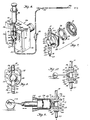
- FIGURE 1 is a perspective view illustrating the infusion pump system of this invention connected to a standard I.V. administration set which is shown in side elevation.
- FIGURE 2 is a view in vertical section taken along line 2-2 of FIGURE 1 illustrating the mounting of the pumping chamber within the housing.
- FIGURE 3 is a view in front elevation of the infusion pump system of FIGURE 1 with mounting covers for the magnetic means partially broken away removed to show placement of the valved pumping chamber with respect to the magnetic means.
- FIGURES 4 and 4a are side sectional views taken along line 4-4 of the infusion pump system shown in FIGURE 3 showing in FIGURE 4 the engagement of actuating means with the valved pumping chamber and the position of the valve means as the valved pumping chamber first empties and in FIGURE 4a the filling of the pump chamber with fluid..
- FIGURE 5 is a front view in elevation of the valved pumping chamber shown in FIGURE 1 illustrating the pumping chamber side.
- FIGURE 6 is a perspective view of the infusion pump system similar to FIGURE 1 illustrating the infusion pump system integrally connected to a syringe as the fluid source.
- FIGURE 7 is an exploded view of the valved pumping chamber utilized in the infusion pump system of FIGURE 1.
- FIGURE 8 is a view in front elevation and with a portion broken away illustrating an alternate embodiment showing a flapper valve in the inlet port.
- FIGURE 9 is a view in side elevation and partially in vertical section of an infusion pump system using a syringe pumping chamber together with magnetically actuated inlet and outlet valves.
- FIGURE 10 is a view in side elevation of an infusion pump system using a section of tubing as a pumping chamber together with magnetically actuated inlet and outlet valves.
- Proceeding to a detailed description of one embodiment of the present invention illustrated in FIGURES 1-5, the valved pumping chamber generally 99 is shown in FIGURE 1 is used in an infusion pump system generally 39. As best seen in FIGURE 1, the inlet port 11 of the
valved pumping chamber 99 is mounted downstream from anair trap 98 and interconnected byupstream tubing 10 to afluid source 35 throughdrip chamber 43. Theoutlet port 23 of thevalved pumping chamber 99 is interconnected bydownstream tubing 27 to suitable means for venipuncture such as a catheter orneedle 94. The usual flowcontrol tubing clamp 92 and Y-reseal site 55 are attached totubing 27. FIGURE 2 shows thevalved pumping chamber 99 mounted in pump actuator generally 34, the magnetically permeable inlet flow restricting means orball 13 is magnetically biased againstinlet valve seat 12, thus making it a flow restricting means. Similarly, magnetically permeable outlet flow restricting means orball 25 which similarly serves as a flow restricting means is magnetically biased againstoutlet valve seat 24. When removed from thepump actuator 34, the magneticallypermeable balls valve seats Post members passages containing balls valve seats post members balls valve seats - The mechanical means for retention of the
valved pumping chamber 99 inpump actuator 34 is best seen in FIGURE 1 and 2. In these figures, it will be seen thatvalved pumping chamber 99 andcompartment 51 for accommodating thevalved pumping chamber 99, are positioned so that they are transverse to the line of travel A-A ofplunger member 22 withdiaphragm 21 being centrally contacted thereby. This is afforded by step-like compartment 51 being composed ofside slots opening 85.Side slots Opening 85 receives the diaphragmed portion of thevalved cassette 99.Plunger member 22 moves transversely to the long axis ofopening 85. In this manner mechanical mounting means are provided in thepump actuator 34 which have the same basic external configuration as thevalved pumping chamber 99. - With reference to FIGURES 1 and 2 the
cavity 30 within thepressure chamber 16 ofvalved pumping chamber 99 is interconnected to theupstream tubing 10 of theinfusion delivery system 39 by inlet port 11 and interconnected to thedownstream tubing 27 of theinfusion delivery system 39 byoutlet port 23. - The sectional view in FIGURE 2 shows in more detail the valving arrangement of pumping
chamber 99. Port 11 is in fluid connection withinlet valve assembly 95. Withininlet valve assembly 95inlet valve seat 12 contains abore 44, the opening and closing of which is accomplished by the action ofball 13 which affords a flow restricting means whereinball 13 moves along apath 17, the limits of which areseat 12 andpost member 14. Whenball 13 rests againstpost member 14 an open path is provided whereas a closed flow path is afforded whenball 13 is biased againstinlet valve seat 12. It will be noted thatpost member 14 is in the nature of a restraining means to maintainball 13 in close proximity tovalve seat 12.Pressure chamber 16 anddiaphragm 21 provide acavity 30 for the infusion fluid. Disposed at the opposite end ofvalved pumping chamber 99 isoutlet valve assembly 96 with avalve seat 24 containing abore 45 which is opened and closed in a manner similar to thebore 44 ininlet valve seat 12. This is accomplished by the action ofball 25 which affords a flow restricting means when moved alongpath 20, the limits of which areseat 24 andpost member 26. The open position is described byball 25 resting againstpost member 26 while the closedposition biases ball 25 againstvalve seat 24. Extending beyondpost member 26 isoutlet port 23 which provides a connection fortubing 27. Disposed inpump actuator housing 56 is alimit switch 29 to signal proper seating ofvalved pumping chamber 99 inpump actuator 34. - Referring specifically to FIGURE 3, the mounting covers 52, 53 of pump actuator 34 (FIGURE 1) for
magnets magnetic field 15 at theinlet valve assembly 95 and amagnetic field 28 at theoutlet valve assembly 96 of thevalved pumping chamber 99. In this instance, it will be noted that the ends 60 and 61 of themagnets adjacent ball 13 are spaced a greater distance apart than theends magnets adjacent ball 25. Accordingly, a greater magnetic effect will be produced onball 25 in holding it againstvalve seat 24.Magnets covers pump actuator housing 56. - FIGURES 4 and 4a depict the relative location of
balls plunger member 22 during pump operation. FIGURE 4 depicts thecavity 30 withinvalved pumping chamber 99 at its smallest volume. This condition occurs as fluid is flowing from thecavity 30 throughoutlet valve assembly 96 intodownstream tubing 27. FIGURE 4a depicts thecavity 30 withinvalved pumping chamber 99 at its maximum volume. This condition occurs as fluid is flowing into thecavity 30 throughinlet valve assembly 95 fromupstream tubing 10. FIGURES 4 and 4a read together with FIGURE 8 illustrate thatrigid wall 18 and pumpchamber portion 16 combine to formbase member 80.Cavity 30 is described bypump chamber 16 anddiaphragm 21.Rigid wall 18 provides the surfaces for locating and retaining thevalved pumping chamber 99 incompartment 51 of pump actuator 34 (FIGURES 1, 3 and 6) - Referring now to FIGURE 5, it will be seen that
inlet valve assembly 95 andoutlet valve assembly 96 are mounted on and in fluid connection withpump chamber 16. Mounted on the opposing side is aretainer 31 which provides a flexible diaphragm 21 (FIGURE 2), thus defining a cavity 30 (FIGURE 2). Fluid enters the cavity 30 (FIGURE 2) of theclosed pressure chamber 16 by passing through inlet port 11 intoinlet valve assembly 95, more specifically through thebore 44 of theinlet valve seat 12 past the inletflow restricting means 13. Fluid leaves the cavity 30 (FIGURE 2) of theclosed pressure chamber 16 by passing through theoutlet valve assembly 96, more specifically through thebore 45 of theoutlet valve seat 34, past the outletflow restricting means 25 and out through theoutlet port 23. - FIGURE 6 illustrates the embodiment of the invention wherein a
syringe 36 is the source of fluid rather thancontainer 35. Thesyringe 36 is connected directly or by fluid connecting means toair trap 98. This connection is effected by the frictional fitment of thenozzle portion 40 of thesyringe 36 into anorifice 48 inair trap 98. The entirevalved pumping chamber 99 is positioned within thepump actuator 34 as previously described in FIGURES 2 and 3 with the same reference numerals indicating the same parts. - As indicated in the exploded view of FIGURE 7, closed
pressure chamber 16 ofvalved pumping chamber 99 will be fabricated in three parts. To assemble the pumping chamber,diaphragm 21 will be placed betweenbase member 80 andretainer 31. In this manner theouter portion 82 ofdiaphragm 21 will be frictionally engaged in an interior annular compartment ofbase member 80 andretainer 31. The flexible wall portion 79 ofdiaphragm 21 will be accessible through opening 81 inretainer 31. Thebase member 80 will be sealed to retainingmember 31 by means of ultrasonic welding or a suitable adhesive. This results in apumping cavity 30. The next step in the fabrication will be the placement ofinlet valve assembly 95 andoutlet valve assembly 96 in fluid communication withcavity 30 described within the combination ofbase member 80,diaphragm 21 andretainer 31. This combination of elements becomesvalved pumping chamber 99.Upstream tubing 10 anddownstream tubing 27 may be connected toports 11 and 23 respectively. If required, anadapter 91 may be used to effect fluid-tight connections. It will be appreciated that the inlet andoutlet tubing infusion pump system 39 withinlet tubing 10 being connected through an air trap such as 98 to a standard source of I.V. fluid 35 which includes adrip chamber 43.Outlet tubing 27 will be connected to a catheter orneedle 94 as seen in FIGURE 1. - FIGURE 8 is another alternative embodiment showing a
flapper valve 54 used in place of the magneticallypermeable ball 13 andvalve seat 12 composinginlet valve assembly 95 as seen in FIGURE 2. Theflapper valve 54 consists of a movingmember 49 which is responsive to hydraulic pressure withinclosed pressure chamber 16. Fluid communication betweenupstream tubing 10 andclosed pressure chamber 16 is prevented by seating of movingmember 49 ontostop 50. The same reference characters have been employed to designate components having the same function, construction and relative location as in FIGURES 1-7. - FIGURE 9 is still another alternative embodiment showing a
syringe mechanism 116 as the pumping chamber wherein the same reference numbers have been employed to designate components having the same function, construction and relative location as in FIGURES 1-7.Pressure chamber 116 is formed bysyringe piston head 22 and nozzle end 111 ofsyringe body 110.Inlet valve assembly 95 is biased bymagnetic means 15 andoutlet valve assembly 96 is biased bymagnetic means 28. The internal configuration ofinlet valve assembly 95 andoutlet valve assembly 96 is the same as illustrated in FIGURES 2, 4, 4a, 5 and 7. Rotating means 122 with eccentric movement transforms rotary motion into linear motion supplies reciprocating drive force topiston head 22. - FIGURE 10 is yet another alternative embodiment showing a piece of
flexible tubing 216 as the pumping chamber wherein the same reference characters have been employed to designate compounds having the same function, construction and relative location as in FIGURES 1-7.Pressure chamber 216 is formed within the inside diameter of tubing 217..Inlet valve assembly 95 is biased bymagnetic means 15 andoutlet valve assembly 96 is biased bymagnetic means 28. The internal configuration ofinlet valve assembly 95 andoutlet valve assembly 96 is the same as illustrated in FIGURES 2, 4, 4a, 5 and 7. Rotating means 222 with eccentric movement transforms rotary motion into linear motion supplies reciprocating drive force topiston head 22. - A better understanding of the advantages of the
infusion pump system 39 will be had by a description of its operation. - It is envisioned that sterile
valved pumping chambers 99 with tubing attached will be contained in hermetically sealed packages which will be furnished to health care personnel. Operation of theinfusion pump system 39 will be initiated by removing thevalved pumping chamber 99 from its packaging together withupstream tubing 10 anddownstream tubing 27 connected to the inlet port 11 andoutlet port 23, respectively. The standard on/offslide clamp 93 is positioned to constrictupstream tubing 10.Flow control clamp 92 is positioned to prevent flow throughdownstream tubing 27. Fluid communication will be made withfluid container 35 by puncturing the sealing means of fluid container 35 (FIGURE 1) with the vented piercingpin portion 65 of combined piercing pin anddrip chamber member 43 to establish an appropriate indicator level in the drip chamber 43 (FIGURE 1). Initial emptying of thefluid source 35 is prevented by the constricting of theupstream tubing 10 by the standard on/off, slotted clamp 93 (FIGURE 1). To initiate priming of the system the entirevalved pumping chamber 99 is held vertically in the inverted position with the outlet valve assembly on the top. Flow of fluid into the invertedvalved pumping chamber 99 is initiated by releasing theupstream clamp 93 andflow control clamp 92. Flow of fluid is partially reduced by closingflow control clamp 92 when the fluid reachesflow control clamp 92. Without magnetic bias the magneticallypermeable balls outlet post members Bores seats valved pumping chamber 99 and the remaining portions of the tubing by the influence of the head of fluid pressure caused by elevation of thefluid source 35. The inverting ofvalved pumping chamber 99 and release of theupstream clamp 93 anddownstream clamp 92 will prime theinfusion pump system 39 for operation. Thedownstream clamp 92 is then re-positioned ondownstream tubing 27 to stop fluid flow in theinfusion pump system 39 when all the air has been cleared from the system. Thevalved pumping chamber 99 is now mounted inpump actuator 34 by returning it to its upright position and sliding the primedvalved pumping chamber 99 intocompartment 51.Downstream tubing 27 is now attached to thevenipuncture device 94. Proper seating of thevalved pumping chamber 99 intocompartment 51 ofpump actuator 34 may be determined in two ways. First,limit switch 29 will close an electrical circuit which provides a signal that thevalved pumping chamber 99 is properly in position for operation. Second, magneticallypermeable balls magnets permeable balls outlet post members cavity 30 to the pressure necessary to overcome the biasing force of outletmagnetic means 28.Upstream clamp 93 anddownstream clamp 92 are positioned to allow fluid flow intubing operation pump actuator 34 may be supported by a bedside table or other suitable structure. Controlled flow of fluid is obtained by the buildup and release of fluid pressure in thecavity 30 ofclosed pressure chamber 16. - The reciprocal operating means 22 as depicted in FIGURE 4 may be connected to a stepper motor or any device which provides reciprocating linear motion. The reciprocal operating means 22 engages the
diaphragm 21, moving it to position 38 (FIGURE 4) so as to cause an increase of fluid pressure by a decrease in the volume of thecavity 30 of theclosed pump chamber 16. This increase in fluid pressure acts onball 13 along with - the magnetomotive force of magnetic means 15 (FIGURE 3). These two forces overcome the force of gravity as well as the viscosity of fluid onball 13 and causes theball 13 to press againstinlet valve seat 12, thereby closingbore 44 and forming a fluid-tight seal preventing flow of fluid back into the fluid container 35 (FIGURE 1) throughtubing 10. In this manner there is only unilateral flow through inlet port 11 intocavity 30 ofclosed pressure chamber 16. The increase in fluid pressure within thecavity 30 of theclosed pump chamber 16 is sufficient to overcome the magnetomotive force of magnetic means 28 (FIGURE 3) causing theball 25 to move away from theoutlet valve seat 24 to a position as shown at 42 in travel path 20 (FIGURE 4). Fluid will then pass through bore 45 ofoutlet valve seat 24past ball 25 on throughtubing 27 to the venipuncture site.Diaphragm 21 is permeable to gas but not to liquid. Therefore, as the pressure withincavity 30 of closed pump chamber 16.is increased; any air or gas trapped withincavity 30 is expelled into the atmosphere through the peripheral portion ofdiaphragm 21 that is not in contact with reciprocating means 22. In this mannerinlet valve assembly 95 need only provide uni-directional flow of fluid, not bi-directional flow of both fluid and gas to effect purging of air or gas from thecavity 30. The axial movement of reciprocating means orplunger 22 along line A-A (FIGURE 2) away from thevalved pumping chamber 99 moves diaphragm 21 to a position as shown at 37 is depicted in FIGURE 4a. Volume within thecavity 30 of thepressure chamber 16 is increased thereby causing a decrease in fluid pressure. Downstream from thecavity 30, magnetomotive force from magnetic means 28 (FIGURE 3) causes the lowerflow restricting ball 25 to move from restraining means 26 alongtravel path 20, closing bore 45 and forming a fluid-tight seal withoutlet valve seat 24. The reduction in fluid pressure withincavity 30 ofclosed pressure chamber 16 also causes the force onball 13 from within theclosed pressure chamber 16 to be reduced. - The magnetomotive force of
magnetic field 15 and the fluid pressure withincavity 30 is no longer sufficient to holdball 13 againstinlet seat 12 when placed under the influence of the weight of fluid from the fluid source 35 (FIGURE 1) and theupstream tubing 10. This causesball 13 to move fromvalve seat 12 to a position as shown at 41 alongtravel path 17 in inlet valve 95 (FIGURE 4a). Fluid will now flow from the source 35 (FIGURE 1) throughtubing 10,air trap 98, and through thebore 44 invalve seat 12past ball 13 intocavity 30 ofclosed pressure chamber 16. - Described above is the utilization of magnetically actuated balls with a flexible diaphragm type pumping chamber. Other types of pumping chambers may also be used with magnetically actuated flow restricting means. Shown in FIGURE 9 is a
syringe body 110 which forms apressure chamber 116 in cooperation with the Tee-shaped fitting l12 attached to the nozzle end 111 ofsyringe body 110 and piston head orplunger 22.Plunger 22 is driven by linear drive means 122 which may also be a linear stepper motor. The valving action of magneticallypermeable balls pressure chamber 216.Plunger 22 is driven by a linear drive means 222 which may also be a linear stepper motor. The valving action of magneticallypermeable balls - An inherent feature of this invention is the gas disabling operation. It may best be explained by reference to FIGURES 2, 3, 4 and 4a. The magnetomotive force of
magnetic means 15 is such that inletflow restricting means 13 is urged into the closed position againstvalve seat 12 when there is no fluid in theinfusion pump system 39. If air is drawn into thecavity 30, for example, when thereservoir 35 anddrip chamber 43 are empty, the action of reciprocating means 22 againstdiaphragm 21 will only serve to compress the air in the space over the remaining incompressible fluid which now only partially fillscavity 30. The compression of the air within thecavity 30 of thepressure chamber 16 will be unable to create sufficient pressure withincavity 30 to overcome the magnetomotive force ofmagnetic means 28 holding outlet flow restricting means 25 onoutlet valve seat 24. In this manner air will not be pumped into a patient through the venipuncture. The embodiments shown in FIGURES 9 and 10 will be similarly gas disabling. The ability of this invention to be converted to a gravity flow device may be best explained by reference to FIGURES 2, 3, 4 and 4a. Removal of thevalved pumping chamber 99 frompump actuator 34 will causeballs valve seats paths members balls valve seats tubing 10,air trap 98, upper valve seat bore 44,cavity 30, lower valve seat bore 45 intolower tubing 27. Whileair trap 98 is not required for proper operation ofvalved pumping chamber 99 it provides a means to strip small bubbles from the intravenous fluid just upstream of inlet port 11. Any trapped bubbles of air or gas near the surface of the fluid will join the air space withinair trap 98 rather than remaining with the fluid. Gas disabling of theinfusion pump system 39 by the accumulation of air incavity 30 is thereby prevented. In this regard the inherent gas disabling feature provides an extra measure of safety for the patient and reduces the frequency of flow-alarms. The embodiments shown in FIGURES 9 and 10 may be converted to gravity flow in the same manner asvalved pumping chamber 99. - The
base member 80 shown best in FIGURES 5 and 7 is composed of a clear styrene acrylonitrile plastic. However, it can be formed of a semi-rigid styrene acrylonitrile or other suitable plastic materials such as a clear polycarbonate. A clear acrylonitrile butadiene styrene could be used. Ideally, the retainer 31 (FIGURE 7) will be made from the same material asbase member 80.Diaphragm 21 is made of a gas permeable, hydrophobic silicon elastomer 70 Shore A. Other similar gas permeable, hydrophobic materials could be employed. Valve seats 12 and 24 are fabricated from a silicone rubber. Other suitable materials such as natural rubber or polyurethane may be used. Valve seats 12 and 14 may be shaped such as concave in configuration on the surface meeting theflow restricting balls Balls valve assemblies valved pumping chamber 99 is approximately 1-9/16 inches and dimension B is approximately 1-9/16 inches, a chamber can be fabricated which is adequately fed by and easily connected to vinyl tubing with an approximate 0.100 inside diameter and an approximate 0.138 outside diameter. Should smaller tubing be used anadapter 91 may be placed on either inlet port 11 oroutlet port 23. Satisfactory performance results have been achieved where thecavity 30 is sized to contain approximately 3.0 ml. of fluid. Control over movement ofdiaphragm 21 enables the user to control the volume of fluid pumped. This control may be achieved by proper timing and controlling the stroke length of operating means 22. A displacement volume of 0.5 ml. has proven to be effective in the prevention of gas disabling. Continued contact between operating means 22 anddiaphragm 21 enhances accuracy. Programmed movement of operating means 22 is readily possible with commercially available and relatively inexpensive micro-computer chips. Functions such as flow rate, flow error, delivery volume or occlusion alarm may be easily handled by known digital techniques. It is preferable to design the controller for operating means 22 to provide return strokes of very short duration despite the length of the pumping stroke. In this manner, the flow of medicament into the patient will be nearly constant, interrupted only very briefly for the return stroke of operating means 22. Digital electronics capability makes such operation easily achievable. Upper and lowermagnetic means Pump actuator 34 houses the necessary electronic circuity and operating controls. In addition it provides a mounting for the reciprocating operating means 22.Covers magnetic pieces compartment 51 inpump actuator housing 56 to vertically and horizontally position thevalved pumping chamber 99 with respect to reciprocal operating means 22 andmagnetic means - Performance testing of the described infusion pumping system has revealed that there is approximately a 0.9% change in flow rate when head heights are varied over the usual range found in health care facilities. Changing back pressure on the pump from 6 psi to -2 psi produces less than a 1% change in flow rate.
- Additional testing has revealed that cycling the reciprocal plunger member approximately five times in quick fashion before the administration of liquid begins charges the entire system with adequate internal pressure to assure uniform flow of fluid during the following periods of fluid administration.
- It will thus be seen that through the present invention there is provided a novel pumping system providing a regulated flow of fluids which is simple in its construction and easily used by health care personnel. The small number of components, the simplicity of component design and low component cost allow for ease of manufacture and disposal once used. In particular, the
ports 11 and 23 can also be manufactured to serve as connecting means for theupper tubing 10 andlower tubing 27. - As set forth hereinabove, various alternative embodiments of the pumping system of the present invention are contemplated.
- Thus, in a first embodiment the pumping chamber comprises a flexible means adapted to be engaged by the
reciprocal operating member 22, thediaphragm 21 comprising a substantially flat disc with anouter portion 82 held in part to the pumping chamber by frictional means defined by an annular compartment formed between thebase member 80 and theretainer 31. - The
diaphragm 21 is composed of a hydrophobic material. - In an alternative embodiment the pressure chamber is formed by a
syringe mechanism 116 wherein the flexible means adapted to change the internal volume of the chamber comprises asyringe piston head 22 operatively connected to the respective reciprocal operating member. - In a still further embodiment the pumping chamber comprises a length of
flexible tubing 216 operatively connected with the reciprocal operating member, i.e. thepiston head 22. - In the pumping chamber according to the invention the inlet port to it (11) is preferably positioned diametrically opposite from the outlet port (23) of the chamber.
- Such inlet and outlet ports- are adapted to receive flexible tubing, 10 and 27, respectively.
- As disclosed above the inlet and outlet valve seats are construed and arranged to provide fluid-tight seals in engagement with said flow restricting means.
- The infusion pump according to the invention, as said, comprises a mounting member to position the valve chamber and includes means responsive to the positioning of the valve chamber to generate an electrical signal.
- The infusion pump also comprises first magnetic means (ends 60 and 61 of
magnets 46 and 47) adapted to exert a magnetomotive force on the magnetic ball (13) operatively associated with the inlet valve seat (12) and second magnetic means (ends 62 and 63 of the magnets) exerting a greater magnetomotive force on themagnetic ball 25 operatively associated withoutlet valve seat 24. - The foregoing invention can now be practiced by those skilled in the art. Such skilled persons will know that the invention is not necessarily restricted to the particular embodiments presented herein. The scope of the invention is to be defined by the terms of the following claims as given meaning by the preceding description.
Claims (10)
Applications Claiming Priority (2)
| Application Number | Priority Date | Filing Date | Title |
|---|---|---|---|
| US06/447,377 US4519792A (en) | 1982-12-06 | 1982-12-06 | Infusion pump system |
| US447377 | 1982-12-06 |
Publications (2)
| Publication Number | Publication Date |
|---|---|
| EP0110276A2 true EP0110276A2 (en) | 1984-06-13 |
| EP0110276A3 EP0110276A3 (en) | 1986-03-12 |
Family
ID=23776136
Family Applications (1)
| Application Number | Title | Priority Date | Filing Date |
|---|---|---|---|
| EP83111601A Withdrawn EP0110276A3 (en) | 1982-12-06 | 1983-11-21 | Infusion pump system |
Country Status (7)
| Country | Link |
|---|---|
| US (1) | US4519792A (en) |
| EP (1) | EP0110276A3 (en) |
| JP (1) | JPS59111765A (en) |
| AU (1) | AU560212B2 (en) |
| CA (1) | CA1233069A (en) |
| DK (1) | DK562083A (en) |
| ES (1) | ES527805A0 (en) |
Cited By (12)
| Publication number | Priority date | Publication date | Assignee | Title |
|---|---|---|---|---|
| EP0193266A2 (en) * | 1985-02-25 | 1986-09-03 | Henley Investments, Inc. | Gravity flow cassette |
| EP0197705A1 (en) * | 1985-03-27 | 1986-10-15 | McGAW, Inc. | Infusion pump with disposable cassette |
| EP0258424A1 (en) * | 1986-03-04 | 1988-03-09 | Deka Products Lp | Intravenous line valving system. |
| EP0275213A2 (en) * | 1987-01-16 | 1988-07-20 | Pacesetter Infusion Ltd. | Medication infusion system |
| EP0307069A2 (en) * | 1987-07-20 | 1989-03-15 | D.F. Laboratories Ltd. | Disposable cell-diaphragm pump |
| EP0398583A2 (en) * | 1989-05-11 | 1990-11-22 | Bespak plc | Pump apparatus for biomedical use |
| NL9401472A (en) * | 1994-09-09 | 1996-04-01 | Drs Theodorus Jacobus Wijlhuiz | Medication vessel for infusion apparatus |
| EP0821600A1 (en) * | 1995-04-20 | 1998-02-04 | Invasatec, Inc. | Self-purging angiographic injector |
| EP2060544A1 (en) | 2007-11-16 | 2009-05-20 | APV Systems Ltd. | Method and apparatus for preparing material for microbiologic fermentation |
| WO2018215543A1 (en) * | 2017-05-23 | 2018-11-29 | B. Braun Melsungen Ag | Infusion pump comprising a pump module that can assume different operating states |
| WO2020025484A1 (en) * | 2018-08-01 | 2020-02-06 | B. Braun Melsungen Ag | Infusion system having an infusion pump and having a pump module that can be coupled thereto |
| US20210223081A1 (en) * | 2018-06-06 | 2021-07-22 | Prominent Gmbh | Dosing pump with linear motor |
Families Citing this family (137)
| Publication number | Priority date | Publication date | Assignee | Title |
|---|---|---|---|---|
| US4626241A (en) * | 1985-03-06 | 1986-12-02 | Ivac Corporation | Apparatus and method for controlling the parenteral administration of fluids |
| US4608042A (en) * | 1985-09-25 | 1986-08-26 | Warner-Lambert Company | Apparatus for sequential infusion of medical solutions |
| US5195986A (en) * | 1986-03-04 | 1993-03-23 | Deka Products Limited Partnership | Integral intravenous fluid delivery device |
| US4842498A (en) * | 1987-01-20 | 1989-06-27 | Thomas Industries, Inc. | Diaphragm compressor |
| US4846637A (en) * | 1987-04-10 | 1989-07-11 | Alderson Richard K | Infusion pump system and conduit therefor |
| US4798589A (en) * | 1987-06-15 | 1989-01-17 | Fisher Scientific Group Inc. | Diaphragm pump cassette |
| US4850807A (en) * | 1987-06-16 | 1989-07-25 | Frantz Medical Development Ltd. | Disposable cassette for fluid delivery pump systems |
| US5237309A (en) * | 1987-07-20 | 1993-08-17 | Frantz Medical Development, Ltd. | Pump cassette and method of pumping |
| US5201711A (en) * | 1987-09-30 | 1993-04-13 | Sherwood Medical Company | Safety interlock system for medical fluid pumps |
| US4872813A (en) * | 1987-12-01 | 1989-10-10 | Pacesetter Infusion, Ltd. | Disposable cassette for a medication infusion system |
| US5803712A (en) | 1988-05-17 | 1998-09-08 | Patient Solutions, Inc. | Method of measuring an occlusion in an infusion device with disposable elements |
| US5246347A (en) * | 1988-05-17 | 1993-09-21 | Patients Solutions, Inc. | Infusion device with disposable elements |
| US5074756A (en) | 1988-05-17 | 1991-12-24 | Patient Solutions, Inc. | Infusion device with disposable elements |
| US5205819A (en) * | 1989-05-11 | 1993-04-27 | Bespak Plc | Pump apparatus for biomedical use |
| US5190527A (en) * | 1989-09-25 | 1993-03-02 | Baxter International Inc. | Intravenous metering device |
| US5108373A (en) * | 1989-09-25 | 1992-04-28 | Baxter International Inc. | Intravenous metering device |
| US5017192A (en) * | 1989-10-20 | 1991-05-21 | Minnesota Mining And Manufacturing Company | Free flow prevention system for infusion pump |
| US5261883A (en) * | 1990-10-26 | 1993-11-16 | Alcon Surgical, Inc. | Portable apparatus for controlling fluid flow to a surgical site |
| US5250027A (en) * | 1991-10-08 | 1993-10-05 | Sherwood Medical Company | Peristaltic infusion device with backpack sensor |
| CA2064134A1 (en) * | 1991-04-23 | 1992-10-24 | Gary A. Thill | Free flow prevention system for infusion pump |
| US5290239A (en) * | 1991-09-26 | 1994-03-01 | Baxter International, Inc. | Intravenous tube safety apparatus |
| US5772637A (en) * | 1995-06-07 | 1998-06-30 | Deka Products Limited Partnership | Intravenous-line flow-control system |
| US5431634A (en) * | 1992-03-06 | 1995-07-11 | Baxter International Inc. | Ambulatory pump |
| US5433351A (en) * | 1992-05-01 | 1995-07-18 | Misuzuerie Co., Ltd. | Controlled liquid dispensing apparatus |
| CA2137772A1 (en) * | 1992-06-09 | 1993-12-23 | Shan Padda | Programmable infusion pump with interchangeable tubing |
| DE4336336A1 (en) * | 1992-11-23 | 1994-05-26 | Lang Volker | Cassette infusion system |
| US5558639A (en) * | 1993-06-10 | 1996-09-24 | Gangemi; Ronald J. | Ambulatory patient infusion apparatus |
| US5401256A (en) * | 1994-01-14 | 1995-03-28 | Minnesota Mining And Manufacturing Company | Flexible clamp for use in IV tubing set |
| US5609575A (en) * | 1994-04-11 | 1997-03-11 | Graseby Medical Limited | Infusion pump and method with dose-rate calculation |
| US5499906A (en) * | 1994-08-08 | 1996-03-19 | Ivac Corporation | IV fluid delivery system |
| US5513957A (en) * | 1994-08-08 | 1996-05-07 | Ivac Corporation | IV fluid delivery system |
| US5549460A (en) * | 1994-08-08 | 1996-08-27 | Ivac Corporation | IV fluid delivery system |
| US5511951A (en) * | 1994-08-08 | 1996-04-30 | O'leary; Stephen H. | IV fluid delivery system |
| US5575632A (en) * | 1994-09-12 | 1996-11-19 | Ivac Medical Systems, Inc. | Engineered pumping segment |
| US5568912A (en) * | 1994-09-12 | 1996-10-29 | Ivac Corporation | Sliding flow controller having channel with variable size groove |
| US5601420A (en) * | 1994-09-12 | 1997-02-11 | Ivac Medical Systems, Inc. | Interlock, latching, and retaining mechanism for an infusion pump |
| US5563347A (en) * | 1994-09-12 | 1996-10-08 | Ivac Corp | Pressure sensing vessel adapted to be preloaded against a sensor |
| US5603613A (en) * | 1994-09-12 | 1997-02-18 | Ivac Corp | Fluid delivery system having an air bubble ejector |
| US6234773B1 (en) | 1994-12-06 | 2001-05-22 | B-Braun Medical, Inc. | Linear peristaltic pump with reshaping fingers interdigitated with pumping elements |
| US5527295A (en) * | 1995-02-22 | 1996-06-18 | Wing; Michael L. | Gravitational, magnetic, floating ball valve |
| US5628619A (en) * | 1995-03-06 | 1997-05-13 | Sabratek Corporation | Infusion pump having power-saving modes |
| US5904668A (en) * | 1995-03-06 | 1999-05-18 | Sabratek Corporation | Cassette for an infusion pump |
| US5620312A (en) * | 1995-03-06 | 1997-04-15 | Sabratek Corporation | Infusion pump with dual-latching mechanism |
| US5637093A (en) * | 1995-03-06 | 1997-06-10 | Sabratek Corporation | Infusion pump with selective backlight |
| US5795327A (en) * | 1995-03-06 | 1998-08-18 | Sabratek Corporation | Infusion pump with historical data recording |
| US5957669A (en) * | 1995-06-15 | 1999-09-28 | United States Filter Corporation | Diaphragm pump including improved drive mechanism and pump head |
| WO1997002852A1 (en) * | 1995-07-10 | 1997-01-30 | Compagnie De Developpement Aguettant | Liquid drug infusion pump |
| US6354819B1 (en) | 1996-06-14 | 2002-03-12 | United States Filter Corporation | Diaphragm pump including improved drive mechanism and pump head |
| US5718238A (en) * | 1996-09-11 | 1998-02-17 | Storz Instrument Company | Fluid collection cassette identification scheme |
| WO1998029662A1 (en) * | 1996-12-31 | 1998-07-09 | Elan Corporation, Plc | A device for generating a pulsatile fluid drug flow |
| US5718255A (en) * | 1997-01-09 | 1998-02-17 | Generac Corporation | Flow-responsive diverting valve |
| US6468242B1 (en) | 1998-03-06 | 2002-10-22 | Baxter International Inc. | Medical apparatus with patient data recording |
| US6517508B1 (en) * | 1999-11-03 | 2003-02-11 | Dsu Medical Corporation | Set for blood processing |
| SE523272C2 (en) * | 1999-11-15 | 2004-04-06 | Aneo Ab | System for intravenous anesthesia for the control of a drug delivery to a patient |
| US6989891B2 (en) | 2001-11-08 | 2006-01-24 | Optiscan Biomedical Corporation | Device and method for in vitro determination of analyte concentrations within body fluids |
| US20060173395A1 (en) * | 2002-02-12 | 2006-08-03 | Brugger James M | Set for blood processing |
| US7527608B2 (en) * | 2002-08-12 | 2009-05-05 | Lma North America, Inc. | Medication infusion and aspiration system and method |
| EP1475113A1 (en) * | 2003-05-08 | 2004-11-10 | Novo Nordisk A/S | External needle inserter |
| DE602004028231D1 (en) * | 2003-05-08 | 2010-09-02 | Novo Nordisk As | A SKIN-INJECTABLE INJECTION DEVICE WITH A SEPARATE ACTUATING PART FOR INTRODUCING THE NEEDLE |
| ATE392223T1 (en) * | 2003-05-08 | 2008-05-15 | Novo Nordisk As | INTERNAL NEEDLE INTRODUCER |
| EP1502613A1 (en) * | 2003-08-01 | 2005-02-02 | Novo Nordisk A/S | Needle device with retraction means |
| KR20060099520A (en) * | 2003-10-21 | 2006-09-19 | 노보 노르디스크 에이/에스 | Medical skin mountable device |
| WO2005094920A1 (en) * | 2004-03-30 | 2005-10-13 | Novo Nordisk A/S | Actuator system comprising lever mechanism |
| US7794423B2 (en) * | 2004-05-25 | 2010-09-14 | Covidien Ag | Re-certification system for a flow control apparatus |
| US7462170B2 (en) * | 2004-05-25 | 2008-12-09 | Covidien Ag | Administration feeding set and valve mechanism |
| CN101027095B (en) * | 2004-09-22 | 2010-09-29 | 诺和诺德公司 | Medical device with cannula inserter |
| WO2006032692A1 (en) * | 2004-09-22 | 2006-03-30 | Novo Nordisk A/S | Medical device with cannula inserter |
| US7516873B2 (en) * | 2004-11-10 | 2009-04-14 | Samw Hong Jen Wang | Fluid dispensing or feeding device |
| US20090048563A1 (en) * | 2004-12-06 | 2009-02-19 | Novo Nordisk A/S | Ventilated Skin Mountable Device |
| CN101107028B (en) * | 2005-01-24 | 2013-04-10 | 诺和诺德公司 | Transcutaneous device assembly |
| US7860542B2 (en) * | 2005-02-14 | 2010-12-28 | Optiscan Biomedical Corporation | Analyte detection system with reduced sample volume |
| US8251907B2 (en) * | 2005-02-14 | 2012-08-28 | Optiscan Biomedical Corporation | System and method for determining a treatment dose for a patient |
| US20060194325A1 (en) * | 2005-02-14 | 2006-08-31 | Gable Jennifer H | Fluid handling cassette with a fluid control interface |
| US8936755B2 (en) | 2005-03-02 | 2015-01-20 | Optiscan Biomedical Corporation | Bodily fluid composition analyzer with disposable cassette |
| DE102005042092B4 (en) * | 2005-03-17 | 2021-06-17 | Kastriot Merlaku | Vibrator for erotic purposes for insertion into a vagina |
| EP1898975A2 (en) * | 2005-05-13 | 2008-03-19 | Novo Nordisk A/S | Medical device adapted to detect disengagement of a transcutaneous device |
| US8197231B2 (en) | 2005-07-13 | 2012-06-12 | Purity Solutions Llc | Diaphragm pump and related methods |
| US20080161723A1 (en) * | 2006-09-06 | 2008-07-03 | Optiscan Biomedical Corporation | Infusion flow interruption method and apparatus |
| US9561001B2 (en) | 2005-10-06 | 2017-02-07 | Optiscan Biomedical Corporation | Fluid handling cassette system for body fluid analyzer |
| US8960194B2 (en) * | 2006-02-23 | 2015-02-24 | Spacelabs Healthcare Llc | Ventilator for rapid response to respiratory disease conditions |
| CN101401314B (en) * | 2006-03-13 | 2013-04-24 | 诺沃-诺迪斯克有限公司 | Medical system comprising dual purpose communication means |
| WO2007104755A1 (en) * | 2006-03-13 | 2007-09-20 | Novo Nordisk A/S | Secure pairing of electronic devices using dual means of communication |
| WO2007122207A1 (en) * | 2006-04-26 | 2007-11-01 | Novo Nordisk A/S | Skin-mountable device in packaging comprising coated seal member |
| US20070269322A1 (en) * | 2006-05-19 | 2007-11-22 | Falk Theodore J | Low power electromagnetic pump |
| WO2007141210A1 (en) * | 2006-06-06 | 2007-12-13 | Novo Nordisk A/S | Assembly comprising skin-mountable device and packaging therefore |
| US20100063448A1 (en) * | 2007-03-06 | 2010-03-11 | Novo Nordisk A/S | Pump assembly comprising actuator system |
| WO2008144575A2 (en) * | 2007-05-18 | 2008-11-27 | Optiscan Biomedical Corporation | Fluid injection and safety system |
| US20120226235A1 (en) * | 2007-08-13 | 2012-09-06 | Novo Nordisk A/S | Method and arrangement for reducing air bubbles in fluidic system |
| EP2178476B1 (en) * | 2007-08-14 | 2016-10-05 | ZOLL Circulation, Inc. | Methods and systems for inducing therapeutic hypothermia in a pre-hospital, field, or ambulance setting |
| US20090112155A1 (en) * | 2007-10-30 | 2009-04-30 | Lifescan, Inc. | Micro Diaphragm Pump |
| WO2009056616A1 (en) * | 2007-10-31 | 2009-05-07 | Novo Nordisk A/S | Non-porous material as sterilization barrier |
| US8517990B2 (en) | 2007-12-18 | 2013-08-27 | Hospira, Inc. | User interface improvements for medical devices |
| US8105269B2 (en) | 2008-10-24 | 2012-01-31 | Baxter International Inc. | In situ tubing measurements for infusion pumps |
| US20100211002A1 (en) * | 2009-02-18 | 2010-08-19 | Davis David L | Electromagnetic infusion pump with integral flow monitor |
| US8353864B2 (en) * | 2009-02-18 | 2013-01-15 | Davis David L | Low cost disposable infusion pump |
| US8197235B2 (en) * | 2009-02-18 | 2012-06-12 | Davis David L | Infusion pump with integrated permanent magnet |
| US8137083B2 (en) | 2009-03-11 | 2012-03-20 | Baxter International Inc. | Infusion pump actuators, system and method for controlling medical fluid flowrate |
| US9554742B2 (en) | 2009-07-20 | 2017-01-31 | Optiscan Biomedical Corporation | Fluid analysis system |
| EP2456355B1 (en) | 2009-07-20 | 2016-09-14 | Optiscan Biomedical Corporation | Adjustable connector and dead space reduction |
| EP3760180A3 (en) | 2009-07-29 | 2021-01-20 | ICU Medical, Inc. | Fluid transfer devices and methods of use |
| US8337175B2 (en) | 2009-12-22 | 2012-12-25 | Smith & Nephew, Inc. | Disposable pumping system and coupler |
| US8382447B2 (en) | 2009-12-31 | 2013-02-26 | Baxter International, Inc. | Shuttle pump with controlled geometry |
| CA2784209C (en) | 2010-01-29 | 2018-10-30 | Kci Licensing, Inc. | Wound treatment apparatuses and methods for controlled delivery of fluids to a wound |
| US8690830B2 (en) * | 2010-05-26 | 2014-04-08 | Innovative Micro Technology | In-plane electromagnetic MEMS pump |
| US8567235B2 (en) | 2010-06-29 | 2013-10-29 | Baxter International Inc. | Tube measurement technique using linear actuator and pressure sensor |
| TWI473942B (en) * | 2010-09-09 | 2015-02-21 | Tom M Simmons | Reciprocating fluid pumps including magnets, devices including magnets for use with reciprocating fluid pumps, and related methods |
| US9506457B2 (en) | 2010-10-01 | 2016-11-29 | Carefusion 303, Inc. | Contactless fluid pumping method and apparatus |
| EP2729784A4 (en) | 2011-07-06 | 2015-05-13 | Optiscan Biomedical Corp | Sample cell for fluid analysis system |
| CA2844807C (en) | 2011-08-19 | 2022-07-26 | Hospira, Inc. | Systems and methods for a graphical interface including a graphical representation of medical data |
| WO2013068899A1 (en) * | 2011-11-07 | 2013-05-16 | Koninklijke Philips Electronics N.V. | System and method for monitoring composition in a sidestream system using a disposable sampling chamber |
| US10022498B2 (en) | 2011-12-16 | 2018-07-17 | Icu Medical, Inc. | System for monitoring and delivering medication to a patient and method of using the same to minimize the risks associated with automated therapy |
| CA3075368C (en) | 2011-12-22 | 2023-07-11 | Icu Medical, Inc. | Fluid transfer devices and methods of use |
| JP6306566B2 (en) | 2012-03-30 | 2018-04-04 | アイシーユー・メディカル・インコーポレーテッド | Air detection system and method for detecting air in an infusion system pump |
| US9610392B2 (en) | 2012-06-08 | 2017-04-04 | Fresenius Medical Care Holdings, Inc. | Medical fluid cassettes and related systems and methods |
| ES2743160T3 (en) | 2012-07-31 | 2020-02-18 | Icu Medical Inc | Patient care system for critical medications |
| WO2014190264A1 (en) | 2013-05-24 | 2014-11-27 | Hospira, Inc. | Multi-sensor infusion system for detecting air or an occlusion in the infusion system |
| AU2014274122A1 (en) | 2013-05-29 | 2016-01-21 | Icu Medical, Inc. | Infusion system and method of use which prevents over-saturation of an analog-to-digital converter |
| ES2838450T3 (en) | 2013-05-29 | 2021-07-02 | Icu Medical Inc | Infusion set that uses one or more sensors and additional information to make an air determination relative to the infusion set |
| US9714650B2 (en) | 2013-06-11 | 2017-07-25 | Matthew G. Morris, Jr. | Pumping system |
| US9504522B2 (en) * | 2013-06-25 | 2016-11-29 | Biosense Webster (Israel) Ltd. | Electrocardiogram noise reduction |
| WO2015077184A1 (en) | 2013-11-25 | 2015-05-28 | Icu Medical, Inc. | Methods and system for filling iv bags with therapeutic fluid |
| JP6636442B2 (en) | 2014-02-28 | 2020-01-29 | アイシーユー・メディカル・インコーポレーテッド | Infusion systems and methods utilizing dual wavelength optical in-pipe air detection |
| AU2015266706B2 (en) | 2014-05-29 | 2020-01-30 | Icu Medical, Inc. | Infusion system and pump with configurable closed loop delivery rate catch-up |
| WO2016057981A1 (en) | 2014-10-10 | 2016-04-14 | Nxstage Medical, Inc. | Pinch clamp devices, methods, and systems |
| US11344668B2 (en) | 2014-12-19 | 2022-05-31 | Icu Medical, Inc. | Infusion system with concurrent TPN/insulin infusion |
| US10850024B2 (en) | 2015-03-02 | 2020-12-01 | Icu Medical, Inc. | Infusion system, device, and method having advanced infusion features |
| AU2016365335B2 (en) | 2015-12-04 | 2021-10-21 | Icu Medical, Inc. | Systems methods and components for transferring medical fluids |
| EP3454922B1 (en) | 2016-05-13 | 2022-04-06 | ICU Medical, Inc. | Infusion pump system with common line auto flush |
| CA3027176A1 (en) | 2016-06-10 | 2017-12-14 | Icu Medical, Inc. | Acoustic flow sensor for continuous medication flow measurements and feedback control of infusion |
| USD851745S1 (en) | 2016-07-19 | 2019-06-18 | Icu Medical, Inc. | Medical fluid transfer system |
| EP3487468A4 (en) | 2016-07-25 | 2020-03-25 | ICU Medical, Inc. | Systems, methods, and components for trapping air bubbles in medical fluid transfer modules and systems |
| US10089055B1 (en) | 2017-12-27 | 2018-10-02 | Icu Medical, Inc. | Synchronized display of screen content on networked devices |
| CN108498900A (en) * | 2018-04-26 | 2018-09-07 | 上海富吉医疗器械有限公司 | The accurate device and its intravenous delivery system for adjusting flow velocity |
| US11278671B2 (en) | 2019-12-04 | 2022-03-22 | Icu Medical, Inc. | Infusion pump with safety sequence keypad |
| US11590057B2 (en) | 2020-04-03 | 2023-02-28 | Icu Medical, Inc. | Systems, methods, and components for transferring medical fluids |
| WO2022020184A1 (en) | 2020-07-21 | 2022-01-27 | Icu Medical, Inc. | Fluid transfer devices and methods of use |
| US11135360B1 (en) | 2020-12-07 | 2021-10-05 | Icu Medical, Inc. | Concurrent infusion with common line auto flush |
Citations (7)
| Publication number | Priority date | Publication date | Assignee | Title |
|---|---|---|---|---|
| US2646071A (en) * | 1948-12-29 | 1953-07-21 | Wagner William | Magnetic check valve |
| FR2100563A2 (en) * | 1970-07-27 | 1972-03-24 | Derouineau Rene | |
| US4038981A (en) * | 1974-07-26 | 1977-08-02 | Burron Medical Products, Inc. | Electronically controlled intravenous infusion set |
| US4126132A (en) * | 1975-07-28 | 1978-11-21 | Andros Incorporated | Intravenous and intra arterial delivery system |
| US4142524A (en) * | 1977-06-02 | 1979-03-06 | Andros Incorporated | Cassette for intravenous delivery system |
| SU862953A1 (en) * | 1979-10-10 | 1981-09-18 | Киеский Научно-Исследовательский Институт Нейрохирургии | Device for intra-arterial injecting medicaments |
| US4437815A (en) * | 1979-09-27 | 1984-03-20 | Mcmullen John Kenneth | Pump, and an apparatus incorporating the pump for infusing liquid medicine |
Family Cites Families (5)
| Publication number | Priority date | Publication date | Assignee | Title |
|---|---|---|---|---|
| US3559644A (en) * | 1967-12-14 | 1971-02-02 | Robert F Shaw | Liquid infusion apparatus |
| US3605741A (en) * | 1969-06-09 | 1971-09-20 | Jordan L Spencer | Intravenous flow control system |
| US3890968A (en) * | 1971-06-25 | 1975-06-24 | Sci Systems Inc | Fluid flow control means |
| CA1083002A (en) * | 1975-12-03 | 1980-08-05 | Robert J. Lefevre | Electronically controlled intravenous infusion set |
| US4230244A (en) * | 1979-08-30 | 1980-10-28 | Baxter Travenol Laboratories, Inc. | Fluid-flow limiting apparatus for use with intravenous-solution administering equipment |
-
1982
- 1982-12-06 US US06/447,377 patent/US4519792A/en not_active Expired - Lifetime
-
1983
- 1983-11-17 AU AU21458/83A patent/AU560212B2/en not_active Ceased
- 1983-11-21 EP EP83111601A patent/EP0110276A3/en not_active Withdrawn
- 1983-12-02 CA CA000442470A patent/CA1233069A/en not_active Expired
- 1983-12-05 ES ES527805A patent/ES527805A0/en active Granted
- 1983-12-06 DK DK562083A patent/DK562083A/en not_active Application Discontinuation
- 1983-12-06 JP JP58229254A patent/JPS59111765A/en active Pending
Patent Citations (7)
| Publication number | Priority date | Publication date | Assignee | Title |
|---|---|---|---|---|
| US2646071A (en) * | 1948-12-29 | 1953-07-21 | Wagner William | Magnetic check valve |
| FR2100563A2 (en) * | 1970-07-27 | 1972-03-24 | Derouineau Rene | |
| US4038981A (en) * | 1974-07-26 | 1977-08-02 | Burron Medical Products, Inc. | Electronically controlled intravenous infusion set |
| US4126132A (en) * | 1975-07-28 | 1978-11-21 | Andros Incorporated | Intravenous and intra arterial delivery system |
| US4142524A (en) * | 1977-06-02 | 1979-03-06 | Andros Incorporated | Cassette for intravenous delivery system |
| US4437815A (en) * | 1979-09-27 | 1984-03-20 | Mcmullen John Kenneth | Pump, and an apparatus incorporating the pump for infusing liquid medicine |
| SU862953A1 (en) * | 1979-10-10 | 1981-09-18 | Киеский Научно-Исследовательский Институт Нейрохирургии | Device for intra-arterial injecting medicaments |
Cited By (25)
| Publication number | Priority date | Publication date | Assignee | Title |
|---|---|---|---|---|
| EP0193266A2 (en) * | 1985-02-25 | 1986-09-03 | Henley Investments, Inc. | Gravity flow cassette |
| EP0193266A3 (en) * | 1985-02-25 | 1987-02-25 | Warner-Lambert Company | Gravity flow cassette |
| EP0197705A1 (en) * | 1985-03-27 | 1986-10-15 | McGAW, Inc. | Infusion pump with disposable cassette |
| EP0450736A1 (en) * | 1985-03-27 | 1991-10-09 | McGAW, Inc. | Infusion pump with disposable cassette |
| EP0258424A1 (en) * | 1986-03-04 | 1988-03-09 | Deka Products Lp | Intravenous line valving system. |
| EP0258424B1 (en) * | 1986-03-04 | 1991-09-18 | Products Limited Partnership Deka | Intravenous line valving system |
| EP0275213A2 (en) * | 1987-01-16 | 1988-07-20 | Pacesetter Infusion Ltd. | Medication infusion system |
| EP0275213A3 (en) * | 1987-01-16 | 1989-03-22 | Pacesetter Infusion Ltd. | Medication infusion system |
| EP0307069A2 (en) * | 1987-07-20 | 1989-03-15 | D.F. Laboratories Ltd. | Disposable cell-diaphragm pump |
| EP0307069A3 (en) * | 1987-07-20 | 1990-04-18 | D.F. Laboratories Ltd. | Disposable cell-diaphragm pump |
| EP0398583A2 (en) * | 1989-05-11 | 1990-11-22 | Bespak plc | Pump apparatus for biomedical use |
| EP0398583A3 (en) * | 1989-05-11 | 1991-03-27 | Bespak plc | Pump apparatus for biomedical use |
| NL9401472A (en) * | 1994-09-09 | 1996-04-01 | Drs Theodorus Jacobus Wijlhuiz | Medication vessel for infusion apparatus |
| EP0821600A1 (en) * | 1995-04-20 | 1998-02-04 | Invasatec, Inc. | Self-purging angiographic injector |
| EP0821600A4 (en) * | 1995-04-20 | 1999-12-01 | Invasatec Inc | Self-purging angiographic injector |
| EP1410815A1 (en) * | 1995-04-20 | 2004-04-21 | ACIST Medical Systems, Inc. | Self purging angiographic injector |
| EP2060544A1 (en) | 2007-11-16 | 2009-05-20 | APV Systems Ltd. | Method and apparatus for preparing material for microbiologic fermentation |
| WO2018215543A1 (en) * | 2017-05-23 | 2018-11-29 | B. Braun Melsungen Ag | Infusion pump comprising a pump module that can assume different operating states |
| WO2018215544A1 (en) * | 2017-05-23 | 2018-11-29 | B. Braun Melsungen Ag | Pump module for a medical infusion pump, having different operating states |
| US11395876B2 (en) * | 2017-05-23 | 2022-07-26 | B. Braun Melsungen Ag | Sterile pump module for an infusion pump |
| US20210223081A1 (en) * | 2018-06-06 | 2021-07-22 | Prominent Gmbh | Dosing pump with linear motor |
| US11592324B2 (en) * | 2018-06-06 | 2023-02-28 | Prominent Gmbh | Dosing pump with linear motor |
| WO2020025484A1 (en) * | 2018-08-01 | 2020-02-06 | B. Braun Melsungen Ag | Infusion system having an infusion pump and having a pump module that can be coupled thereto |
| CN112512607A (en) * | 2018-08-01 | 2021-03-16 | B·布莱恩·梅尔松根股份公司 | Infusion system with infusion pump and pump module connectable thereto |
| CN112512607B (en) * | 2018-08-01 | 2023-02-28 | B·布莱恩·梅尔松根股份公司 | Infusion system with an infusion pump and a pump module connectable thereto |
Also Published As
| Publication number | Publication date |
|---|---|
| AU2145883A (en) | 1984-06-14 |
| ES8504467A1 (en) | 1985-05-01 |
| CA1233069A (en) | 1988-02-23 |
| DK562083D0 (en) | 1983-12-06 |
| AU560212B2 (en) | 1987-04-02 |
| EP0110276A3 (en) | 1986-03-12 |
| DK562083A (en) | 1984-06-07 |
| ES527805A0 (en) | 1985-05-01 |
| US4519792A (en) | 1985-05-28 |
| JPS59111765A (en) | 1984-06-28 |
Similar Documents
| Publication | Publication Date | Title |
|---|---|---|
| US4519792A (en) | Infusion pump system | |
| EP0751794B1 (en) | Disposable fluid infusion pumping chamber cassette having a push button flow stop thereon | |
| EP0752897B1 (en) | A push button flow stop useable with a disposable infusion pumping chamber cassette | |
| CA2091604C (en) | Fluid control device including automatic valve | |
| US4199307A (en) | Medical infusion system | |
| US4273121A (en) | Medical infusion system | |
| JP3293822B2 (en) | Continuous / bolus injection device | |
| KR101013538B1 (en) | Controlled-volume infusion device | |
| US3620650A (en) | Gas-disabled liquid-pumping apparatus | |
| KR100360302B1 (en) | Displacement pump | |
| AU642440B2 (en) | Micropump with improved priming | |
| WO1997047339A1 (en) | Gravity infusion set for medical infusions | |
| WO2003075984A1 (en) | Ambulatory infusion membrane pump | |
| US20070287960A1 (en) | Disposable infusion device with medicament level indicator | |
| JP2005507688A (en) | Laminated device for infusion to patients | |
| JPH0515590A (en) | Appliance for self-injection of medical fluid and device using the same | |
| GB2131496A (en) | Apparatus for dispensing infusate to a mammal body | |
| AU3112100A (en) | Metered dose infusion pump and method | |
| CN110201265B (en) | Infusion device | |
| EP0044217A1 (en) | Volumetric pump |
Legal Events
| Date | Code | Title | Description |
|---|---|---|---|
| PUAI | Public reference made under article 153(3) epc to a published international application that has entered the european phase |
Free format text: ORIGINAL CODE: 0009012 |
|
| AK | Designated contracting states |
Designated state(s): AT BE CH DE FR GB IT LI LU NL SE |
|
| PUAL | Search report despatched |
Free format text: ORIGINAL CODE: 0009013 |
|
| AK | Designated contracting states |
Kind code of ref document: A3 Designated state(s): AT BE CH DE FR GB IT LI LU NL SE |
|
| 17P | Request for examination filed |
Effective date: 19860903 |
|
| 17Q | First examination report despatched |
Effective date: 19871201 |
|
| STAA | Information on the status of an ep patent application or granted ep patent |
Free format text: STATUS: THE APPLICATION IS DEEMED TO BE WITHDRAWN |
|
| 18D | Application deemed to be withdrawn |
Effective date: 19880412 |
|
| RIN1 | Information on inventor provided before grant (corrected) |
Inventor name: DAWE, GARFIELD ASBURY |