EP0112361B1 - Radiofrequency transducer and method of using same - Google Patents
Radiofrequency transducer and method of using same Download PDFInfo
- Publication number
- EP0112361B1 EP0112361B1 EP83902109A EP83902109A EP0112361B1 EP 0112361 B1 EP0112361 B1 EP 0112361B1 EP 83902109 A EP83902109 A EP 83902109A EP 83902109 A EP83902109 A EP 83902109A EP 0112361 B1 EP0112361 B1 EP 0112361B1
- Authority
- EP
- European Patent Office
- Prior art keywords
- loop
- connection means
- transducer
- transmission line
- probe assembly
- Prior art date
- Legal status (The legal status is an assumption and is not a legal conclusion. Google has not performed a legal analysis and makes no representation as to the accuracy of the status listed.)
- Expired
Links
Images


Classifications
-
- G—PHYSICS
- G01—MEASURING; TESTING
- G01R—MEASURING ELECTRIC VARIABLES; MEASURING MAGNETIC VARIABLES
- G01R33/00—Arrangements or instruments for measuring magnetic variables
- G01R33/20—Arrangements or instruments for measuring magnetic variables involving magnetic resonance
- G01R33/28—Details of apparatus provided for in groups G01R33/44 - G01R33/64
- G01R33/32—Excitation or detection systems, e.g. using radio frequency signals
- G01R33/34—Constructional details, e.g. resonators, specially adapted to MR
- G01R33/341—Constructional details, e.g. resonators, specially adapted to MR comprising surface coils
-
- G—PHYSICS
- G01—MEASURING; TESTING
- G01R—MEASURING ELECTRIC VARIABLES; MEASURING MAGNETIC VARIABLES
- G01R33/00—Arrangements or instruments for measuring magnetic variables
- G01R33/20—Arrangements or instruments for measuring magnetic variables involving magnetic resonance
- G01R33/28—Details of apparatus provided for in groups G01R33/44 - G01R33/64
- G01R33/32—Excitation or detection systems, e.g. using radio frequency signals
- G01R33/34—Constructional details, e.g. resonators, specially adapted to MR
- G01R33/34007—Manufacture of RF coils, e.g. using printed circuit board technology; additional hardware for providing mechanical support to the RF coil assembly or to part thereof, e.g. a support for moving the coil assembly relative to the remainder of the MR system
Definitions
- the present invention relates to a probe assembly for a nuclear magnetic resonance spectrometer, and with the use of such a transducer in conjunction with a known technique of nuclear magnetic resonance.
- Nuclear magnetic resonance is a well known laboratory technique, which can be used, inter alia for the determination and characterisation of chemical species.
- a substance is subjected to a static magnetic field ("B") and an oscillatory electromagnetic field of angular frequency m.
- B static magnetic field
- y the gyromagnetic ratio which is characteristic of a particular nucleus present in the substance.
- the oscillatory field is normally an electromagnetic one for practical reasons, it should be pointed out that it is only the magnetic component which interacts with the test substance to produce the NMR effect.
- the resonance condition can be detected by absorption of, or absorption und reemission of, the radiofrequency field applied, und indicative of the presence of a particular element comprising that nucleus.
- the way of coupling the radiofrequency source to the particular substance has been to provide a simple loop or coil transducer, designed to generate a radiofrequency magnetic field connected to the RF source by a coaxial cable or other type of RF transmission line.
- variable capacitors are required in the arrangement shown in Figures la and 1b for capacitors C1 and C3, to successfully tune and match the simple coil.
- the stray capacitances of the coil become significant compared with the values required to tune and match the coil.
- the self capacitance of the coil is even more significant if the sample being analysed is conductive, or if it has a high dielectric constant. Under these conditions, the tune and match methods become inefficient and unworkable. This is particularly true for so-called "surface coils" for example of the kind suggested by J.J.H. Ackerman et al (Nature 283,167 (1980)), which are often used in medical and other in vivo applications in which there is physical difficulty in locating the sample at the centre of a loop transducer.
- U.S. patent No. 4095163 there is described a nuclear magnetic resonance pick-up coil circuit having a feature that a series resonant tuned RF pick-up coil has its series resonance impedance matched to the input impedance of a radio frequency amplifier via the intermediary of a transmission line transformer.
- the transmission line transformer includes at least a pair of parallel connected transmission line transformers for reducing the characteristic impedance of the composite transmission line transformer.
- Various forms of coil are shown with various connections, in order to form the transmission line impedance transformer.
- the actual probe coil forming the radio frequency transducer for generating and detecting radio frequency magnetic fields is of conventional design.
- a probe assembly for a nuclear magnetic resonance spectrometer comprising a radio frequency transducer for generating and detecting radio frequency magnetic fields, connection means for connecting the transducer to a radio frequency transmission line leading to a radio frequency source or receiver, and tuning means for tuning and matching the transducer to the said radio frequency transmission line which leads to the source or receiver, characterised in that the transducer comprises a radio frequency coil formed in a configuration including at least one loop, the said coil comprising over at least a portion of the loop a radio frequency transmission line comprising at least first and second elongate conductors spaced by dielectric material, the connection means comprising first connection means for the said first conductor and second connection means for the said second conductor, the connection means for the first conductor being provided at one end of the loop and the connection means for the second conductor being provided at the other end of the loop.
- a probe assembly for a nuclear magnetic resonance spectrometer comprising a radio frequency transducer for generating and detecting radio frequency magnetic fields, connection means for connecting the transducer to a radio frequency transmission line leading to a radio frequency source or receiver, and tuning means for tuning and matching the transducer to the said radio frequency transmission line, which leads to the source or reciever, characterised in that the transducer comprises a radio frequency transmission line formed in a configuration including at least one loop, the said transmission line of the transducer comprising at least first and second elongate conductors spaced by dielectric material, the connection means comprising first connection means for the said first conductor and second connection means for the said second conductor, the connection means for the first conductor being provided at one end of the loop and the connection means for the second conductor being provided at the other end of the loop.
- an RF transducer loop as in effect an RF transmission line, in which additional self capacitance is provided, distributed relatively uniformly around the loop.
- This may be achieved by providing a loop made from first and second elongate electrical conductors spaced by dielectric material.
- the radiofrequency signal source can be applied to the conductors by means ot connectors at opposite ends of the conductors, whereby the effect of series capacitance is provided, which has the effect of lowering the inductance of the loop. This capacitance is distributed relatively evenly around the loop.
- the present invention it is arranged that in the or each loop of the transmission line at least one of the conductors has a connection means coupled to it at one end of the loop and has an open circuit at the other end of the loop. In some preferred forms it is arranged that in the or each loop each of the conductors has a connection means coupled to it at one end of the loop and has an open circuit at the other end of the loop.
- each loop at least one of the conductors has a connection means coupled to it at one end of the loop and has a selectively variable impedance component at the other end of the loop, for example a selectively variable capacitor.
- a selectively variable capacitor allows an extension of the normal working range of the transducer over which a suitable tune and match capacitive network may couple the loop to an NMR spectrometer, as will be described in more detail hereinafter.
- the transducer comprises a single loop, but in many cases two or more loops may be provided.
- the transmission line may include two or more loops arranged substantially parallel to each other and spaced apart in a direction perpendicular to the planes of the loops.
- the transmission line is formed in a configuration including two connected loops, the said connection means being provided at a junction between the two loops, the arrangement being such that the first connection means for the first conductor is provided at one end of one loop and the second connection means for the second conductor is provided at the other end of the said one loop, the arrangement also being such that the first connection means for the first conductor is provided at one end of the other loop, and the second connection means for the second conductor is provided at the other end of the said other loop.
- the transmission line may be formed with two loops arranged in a Helmholtz coil configuration with the loops approximately circular and spaced apart along a common axis, the axial spacing of the two loops being substantially equal to the mean radius of the loops.
- Such an arrangement gives a particularly uniform magnetic field.
- a third loop may be provided mid way between the said two loops, and may also be connected electrically in parallel with the first two loops, to the first and second connection means in corresponding manner.
- additional loops may be added in various configurations depending upon the function required, for example additional turns may be added to the said two loops, provided this meets the functional requirements.
- the transmission line may be formed in a configuration including two or more consecutive loops, the connection means for the first conductor being provided at one end of the series of loops, and the connection means for the second conductor being provided at the other end of the series of loops.
- the series of loops may comprise a helix with the connector means connected at opposed ends of the helix.
- the or each loop is a substantially complete loop with the said ends of the loop in close proximity to each other and with the said connection means for the conductors of the loops in close proximity to each other.
- the or each loop may be substantially circular and, where there are two or more loops, the loops may be coaxial.
- the or each loop may have a rectangular configuration.
- the or each loop may lie on a cylindrical surface and may have a configuration in that surface such that a developed view of the surface shows the coil as having a rectangular configuration.
- the transmission line of the transducer will have only first and second spaced apart elongate conductors, in other arrangements threr or more conductors may be provided.
- the transmission line may comprise first, second and third elongate conductors spaced by dielectric material, said first connection means being connected to said first and third elongate conductors.
- the rf transducer coil in a probe assembly should be thought of as a so-called "transmission line” and its properties predicted using conventional transmission line theory.
- the transmission properties of the loop thus can be arranged to counteract the inductive impedance of its coil geometry.
- the transmission line is an assembly of conductors and insulation material which have predictable and uniform radiofrequency properties in the required frequency range and which can be used to carry rf power.
- the properties of such a transmission line are not a simple sum of the "point" static properties.
- the transducer preferably comprises a single loop or turn, although for certain applications multiple turns may be desirable.
- the dielectric material preferably has very low loss, and the material of choice is polytetrafluoroethylene (PTFE), or a glass laminate incorporating PTFE.
- PTFE polytetrafluoroethylene
- the loop may be thought of in its simplest embodiment as at least two conductors spaced by a uniform amount over their length, formed into a loop, and connected at opposite ends to a tuning and matching circuit. In alternative embodiments, three or more spaced conductors may be utilised. When more than two conductors are used, sets of conductors may bbe connected in parallel.
- the conductors may be formed simply from an appropriate length of coaxial cable, or indeed from two suitable supported strands of wire provided with appropriate connections provided that the rf transmission line properties are suitable.
- the coil comprises a pair of copper strips separated by PTFE tape or the like material, the opposite ends of the strips serving to provide the connection means.
- the conductors may be provided in the form of copper or the like laminate disposed on opposite surfaces of a dielectric sheet. Such a radiator may be formed, for example, by etching a suitable double- sided copper clad laminate board.
- the conductors may be made of silver, gold or any other metal whose magnetic susceptibility lies between approximately -10- 4 cgs units and + 10-4 cgs units.
- the transducer coil according to the invention may be tuned and matched to the RF source and coaxial cable by a simple "T" network, for example as illustrated in Figure 3, which will be described in more detail hereinafter.
- T simple "T” network
- rf current flows completely round the loop in one or other of the conductors. For NMR purposes, this is important, because the current is the source of the rf magnetic field.
- the distributed capacitance means however that voltages are kept low, which minimises the electrical component of the radiated field. Thus, a predictable and reasonably uniform rf magnetic field may be generated.
- the transmission line is chosen for best propagation and minimum loss. This is not necessary for the application to work but is necessary for optimum performance. Optimum performance is obtained when the quality factor, Q, of the resonant tuned and matched assembly is a maximum.
- a transducer assembly for a nuclear magnetic resonance spectrometer comprising a transducer as set forth above, and means for connecting the assembly to a radiofrequency transmission line, for example a coaxial cable, for providing a connection to the spectrometer, and means including a variable capacitor for tuning the probe assembly to the radiofrequency signal and the said transmission line.
- a radiofrequency transmission line for example a coaxial cable
- An NMR spectrometer utilising a probe according to the invention is very useful for in- vivo biochemical measurements, since it is in general important in such measurements for the probe to energise and respond to nuclei at some distance, for example a few cm deep, within the sample. Increasing depth of penetration requires increasingly large transducer coils.
- an NMR spectrometer comprising a transducer coil as set forth above, or a probe as defined above.
- loop geometry may in certain circumstances be desirable to provide a structure in which the two conductors extending parallel over only a portion of the loop, the remainder of the loop being comprised by only one of the conductors.
- circuits shown in Figures 1 (a) and 1(b) are known in themselves when the coils 23 are conventional surface coils for NMR work, the circuits of Figures 1(a) and 1(b) may be used in accordance with the invention where the coils 23 are replaced by transducers embodying the invention.
- FIG 2 is a circuit diagram of a known form of NMR transducer coil, indicated at 30, in which a number of capacitors, shown in the Figure at 31 and 32, are introduced in series with the coil shown diagrammatically at 23.
- the transducer coil 30 is linked to the transmission line 24 by three capacitors 33, 34 and 35 having capacitances C6, C7 and C8, the capacitors 33 and 34 being connected in series between the coil 30 and the transmission line 24, and the capacitor 35 being connected in parallel with the coil 30 at the junction of the two capacitors 33 and 34.
- the additional capacitors 31 and 32 in the coil 30 reduce the effective inductance of the coil and have the added advantage that the high rf voltages are divided across more components.
- such a coilcapacitor structure is mechanical unsound, and may in practice physically break.
- Figures 3,4 and 5 show a perspective view of an actual probe, and Figure 3 shows diagrammatically a form of tuning and matching circuit for the probe.
- a loop for transmitting and receiving a radiofrequency magnetic field comprises a first conductor 1 and a second conductor 2 spaced by a dielectric 3.
- the conductors 1 and 2 are each formed of a rectangular copper strip approximately 4 mm x 1 mm, and are substantially uniform in thickness and spacing over their lengths.
- the dielectric material 3 is formed of a PTFE material, approximately 0.5 mm in thickness. This may be
- a 10 cm diameter coil of the kind illustrated in Figures 4 and 5 and having the material dimensions as described above may be tuned and matched using a simple circuit as illustrated in Figure 3, using variable capacitors 36 and 37, having capacitances C9 and C10 having a range of from 2 pF to 20 pF, at a frequency of 80 MHz.
- a corresponding single turn conventional coil has a capacitance of approximately 5 pF at the same frequency, and cannot therefore be tuned and matched to a 50 Ohm coaxial cable, when used on a sample with high loss.
- the radiofrequency transducer comprises a radiofrequency transmission line which is indicated generally at 40, and comprises the first conductor 1, the second conductor 2, and the dielectric material 3 positioned between the conductors 1 and 2.
- the transmission line 40 is formed into a single loop, indicated generally at 41.
- a first connection means 38 for example a terminal, is connected to the first conductor 1 at one end of the loop 41, which end is indicated generally at 42.
- a second connection means 39 for example a terminal, is connected to the second conductor 2 at the other end of the loop 41, which other end is indicated generally at 43.
- the end of the first conductor 1 which is electrically remote from the first connection means 38 (that is to say which is physically at the end 43 of the loop) is open circuited, and similarly the end of the conductor 2 which is electrically remote from the second connection means 39 (that is to say at the end 42 of the loop 41) is also open circuited.
- FIG 6 is a schematic exploded view of a further embodiment of a transducer according to the invention.
- the transducer comprises two glass -reinforced PTFE boards 10 and 11 providing dielectrics separating three elongate conductors 12, 13 and 14 having a loop configuration.
- Conductors 13 and 14 are in fact disposed on opposite sides of board 11, but are shown exploded for clarity.
- boards 10 and 11 are pressed close together so as to provide a uniform sandwich construction.
- Boards 10 and 11 may advantageously be formed by a chemical etching process using a copper-clad laminate.
- Each conductor 12, 13, 14 is provided with a leg 15,16 and 17 respectively forming a terminal for connection to a radiofrequency source or receiver, the leg 16 of middle conductor 13 being at the opposite end of the conductor from that of conductors 12 and 14.
- conductors 12 and 14 are connected in parallel to one side (the screen) of a coaxial transmission line, conductor 13 being connected to the central conductor.
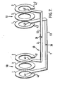
- FIG 7 there is shown a yet further embodiment of a transducer according to the invention, and again Figure 7 is a diagrammatic representation showing the transducer in exploded form.
- the transducer shown in Figure 7 comprises a transmission line indicated generally at40 and comprising a first conductor 1 and a second conductor 2, formed in a configuration including two connected loops indicated generally at 50 and 51, connected by linking strips of conductor 52 and 53.
- the conductors 1 and 2 in loop 50 are separated by a circle of PTFE insulator 3 and the conductors 1 and 2 in the loop 51 are similarly separated by a circle of PTFE insulator material 3.
- the conductors 1 and 2 and insulator 3 in each of the loops 50 and 51 are pressed close together, and the linking strips 52 and 53 are close together, but not superimposed.
- the loops 50 and 51 are in practice arranged in a Helmholtz coil configuration with the loops 50 and 51 circular and spaced apart along a common axis, the axial spacing of the two loops being substantially equal to the mean radius of the loops.
- Connection means for connecting the transmission line 40 to a matching and tuning network comprise first connection means 38 for conductor 1 (for example a terminal), and second connection means 39 for conductor 2 (for example a terminal).
- connection means 38, 39 is provided at a junction between the two loops 50 and 51, the junction being provided by the linking strips 52 and 53.
- the loop 50 is indicated as having one end at 42 and an opposite end at 43.
- the loop 51 is indicated as having one end at 42' and having another end at 43'.
- the arrangement is such that the first connection means 38 for the first conductor 1 is provided at one end 42 of the loop 50, and the second connection means 39 for the second conductor 2 is provided at the other end 43 of the loop 50.
- the arrangement is also such that the first connection means 38 for the first conductor 1 is provided at one end 42' of the other loop 51, and the second connection means 39 for the second conductor 2 is provided at the other end 43' of the said other loop 51.
- Figures 8 and 9 show a further embodiment of a transducer according to the invention.
- Figure 8 shows diagrammatically a pair of loops indicated generally at 60 and 61, wrapped around a former 69.
- the loops 60 and 61 are shown in developed form in Figure 9.
- the loops consist again of two conductors 1 and 2 separated by an insulator 3 and there are provided first and second connection means 38 and 39 positioned on linking strips 63 and 62 of the conductors 1 and 2.
- the arrangement is another example of two parts in parallel to give a more uniform RF magnetic field than that of a single part. Functionally the arrangement can be considered as a distorted version of the coils shown in Figure 7, which have been wrapped around the outside of the former 69, which in this case is a hollow cylinder.
- the arc lengths around the cylinder are 120°, the length along the axis having been chosen to fulfil other requirements for satisfactory operation.
- the strip widths of the conductors 1 and 2 and insulator 3 are shown in step form for the sake of clarity, but in practice the widths would be as shown in Figure 5.
Landscapes
- Physics & Mathematics (AREA)
- Condensed Matter Physics & Semiconductors (AREA)
- General Physics & Mathematics (AREA)
- Magnetic Resonance Imaging Apparatus (AREA)
Abstract
Description
- The present invention relates to a probe assembly for a nuclear magnetic resonance spectrometer, and with the use of such a transducer in conjunction with a known technique of nuclear magnetic resonance.
- Nuclear magnetic resonance (NMR) is a well known laboratory technique, which can be used, inter alia for the determination and characterisation of chemical species. In the classic NMR experiment, a substance is subjected to a static magnetic field ("B") and an oscillatory electromagnetic field of angular frequency m. A condition of resonance occurs when 0) = y B, where y is the gyromagnetic ratio which is characteristic of a particular nucleus present in the substance. Although the oscillatory field is normally an electromagnetic one for practical reasons, it should be pointed out that it is only the magnetic component which interacts with the test substance to produce the NMR effect. The resonance condition can be detected by absorption of, or absorption und reemission of, the radiofrequency field applied, und indicative of the presence of a particular element comprising that nucleus. In general, the way of coupling the radiofrequency source to the particular substance has been to provide a simple loop or coil transducer, designed to generate a radiofrequency magnetic field connected to the RF source by a coaxial cable or other type of RF transmission line.
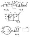
- It is necessary to tune the coil so as to be resonant at the required frequency for the particular nucleus under investigation at the particular magnetic field employed, and to match the impedance of the coil to that of the transmission line (eg. coaxial cable) employed. Examples of typical circuits for tuning and matching are shown in Figures 1a and I b, which will be described in more detail hereinafter. These are the well known "half-T" and PI networks respectively.
- At the high frequencies commonly used in NMR techniques, very low values of variable capacitors are required in the arrangement shown in Figures la and 1b for capacitors C1 and C3, to successfully tune and match the simple coil. In particular, when large coil sizes are employed, for example loops greater than 5 cm or so, and at high field strengths, for example of 1.5 Tesla and above, the stray capacitances of the coil become significant compared with the values required to tune and match the coil. The self capacitance of the coil is even more significant if the sample being analysed is conductive, or if it has a high dielectric constant. Under these conditions, the tune and match methods become inefficient and unworkable. This is particularly true for so-called "surface coils" for example of the kind suggested by J.J.H. Ackerman et al (Nature 283,167 (1980)), which are often used in medical and other in vivo applications in which there is physical difficulty in locating the sample at the centre of a loop transducer.
- One method of overcoming this problem has been to introduce into the region of the coil one or more series capacitors to lower the effective inductance of the coil. An example of such a solution is that proposed by U.W. Alderman and D.M. Grant (J. Magn. Res. 36,447. (1979)). As well as reducing the effective inductance of the coil, the introduction of series capacitance in this way means that the high RF voltages employed are divided across more components. A schematic diagram of such an arrangement is shown in Figure 2, which will be described in more detail hereinafter.
- A difficulty with such proposals has been that they are relatively fragile and prone to break when applied to large rf coils.
- In U.S. patent No. 4095163 (Hlavka) there is described a nuclear magnetic resonance pick-up coil circuit having a feature that a series resonant tuned RF pick-up coil has its series resonance impedance matched to the input impedance of a radio frequency amplifier via the intermediary of a transmission line transformer. In one arrangement the transmission line transformer includes at least a pair of parallel connected transmission line transformers for reducing the characteristic impedance of the composite transmission line transformer. Various forms of coil are shown with various connections, in order to form the transmission line impedance transformer. In the probe, the actual probe coil forming the radio frequency transducer for generating and detecting radio frequency magnetic fields, is of conventional design.
- Other prior art which may be considered in relation to the present invention consists of patent specification US-A-2116734 (Reinartz), and US-A-3184746 (Chatelain). Both these patent specifications describe a short-wave antenna having twin loops arranged for particular directive characteristics.
- It is an object of the present invention to provide a probe assembly for use in nuclear magnetic resonance techniques, which overcome or reduces the problems set out above where a relative large coil size is utilised at high frequencies and the stray capacitancies of the coil become significant compared with the capacitances values required to tune and match the coil to a source or receiver.
- According to the present invention in one aspect there is provided a probe assembly for a nuclear magnetic resonance spectrometer, the probe assembly comprising a radio frequency transducer for generating and detecting radio frequency magnetic fields, connection means for connecting the transducer to a radio frequency transmission line leading to a radio frequency source or receiver, and tuning means for tuning and matching the transducer to the said radio frequency transmission line which leads to the source or receiver, characterised in that the transducer comprises a radio frequency coil formed in a configuration including at least one loop, the said coil comprising over at least a portion of the loop a radio frequency transmission line comprising at least first and second elongate conductors spaced by dielectric material, the connection means comprising first connection means for the said first conductor and second connection means for the said second conductor, the connection means for the first conductor being provided at one end of the loop and the connection means for the second conductor being provided at the other end of the loop.
- In a preferred aspect of the present invention, there is provided a probe assembly for a nuclear magnetic resonance spectrometer, the probe assembly comprising a radio frequency transducer for generating and detecting radio frequency magnetic fields, connection means for connecting the transducer to a radio frequency transmission line leading to a radio frequency source or receiver, and tuning means for tuning and matching the transducer to the said radio frequency transmission line, which leads to the source or reciever, characterised in that the transducer comprises a radio frequency transmission line formed in a configuration including at least one loop, the said transmission line of the transducer comprising at least first and second elongate conductors spaced by dielectric material, the connection means comprising first connection means for the said first conductor and second connection means for the said second conductor, the connection means for the first conductor being provided at one end of the loop and the connection means for the second conductor being provided at the other end of the loop.
- It has now been found, at least in preferred embodiments of the invention that the problem of tuning and matching relative to large RF coils can be overcome by constructing an RF transducer loop as in effect an RF transmission line, in which additional self capacitance is provided, distributed relatively uniformly around the loop. This may be achieved by providing a loop made from first and second elongate electrical conductors spaced by dielectric material. The radiofrequency signal source can be applied to the conductors by means ot connectors at opposite ends of the conductors, whereby the effect of series capacitance is provided, which has the effect of lowering the inductance of the loop. This capacitance is distributed relatively evenly around the loop.
- In some particularly preferred forms of the present invention it is arranged that in the or each loop of the transmission line at least one of the conductors has a connection means coupled to it at one end of the loop and has an open circuit at the other end of the loop. In some preferred forms it is arranged that in the or each loop each of the conductors has a connection means coupled to it at one end of the loop and has an open circuit at the other end of the loop.
- However in alternative arrangements, it may be arranged that in the or each loop at least one of the conductors has a connection means coupled to it at one end of the loop and has a selectively variable impedance component at the other end of the loop, for example a selectively variable capacitor. Such a variable capacitor allows an extension of the normal working range of the transducer over which a suitable tune and match capacitive network may couple the loop to an NMR spectrometer, as will be described in more detail hereinafter.
- In many applications it will be preferred that the transducer comprises a single loop, but in many cases two or more loops may be provided. For example in one configuration the transmission line may include two or more loops arranged substantially parallel to each other and spaced apart in a direction perpendicular to the planes of the loops.
- In one preferred arrangement the transmission line is formed in a configuration including two connected loops, the said connection means being provided at a junction between the two loops, the arrangement being such that the first connection means for the first conductor is provided at one end of one loop and the second connection means for the second conductor is provided at the other end of the said one loop, the arrangement also being such that the first connection means for the first conductor is provided at one end of the other loop, and the second connection means for the second conductor is provided at the other end of the said other loop.
- It is particularly preferred that the transmission line may be formed with two loops arranged in a Helmholtz coil configuration with the loops approximately circular and spaced apart along a common axis, the axial spacing of the two loops being substantially equal to the mean radius of the loops. Such an arrangement gives a particularly uniform magnetic field.
- It is to be appreciated that more than two loops may be provided in a parallel configuration, such as has been set out above, for example a third loop may be provided mid way between the said two loops, and may also be connected electrically in parallel with the first two loops, to the first and second connection means in corresponding manner. In other arrangements additional loops may be added in various configurations depending upon the function required, for example additional turns may be added to the said two loops, provided this meets the functional requirements.
- In other arrangements the transmission line may be formed in a configuration including two or more consecutive loops, the connection means for the first conductor being provided at one end of the series of loops, and the connection means for the second conductor being provided at the other end of the series of loops. For example the series of loops may comprise a helix with the connector means connected at opposed ends of the helix.
- It will normally be preferred that the or each loop is a substantially complete loop with the said ends of the loop in close proximity to each other and with the said connection means for the conductors of the loops in close proximity to each other.
- By way of example, the or each loop may be substantially circular and, where there are two or more loops, the loops may be coaxial. In other arrangements the or each loop may have a rectangular configuration. In some arrangements, the or each loop may lie on a cylindrical surface and may have a configuration in that surface such that a developed view of the surface shows the coil as having a rectangular configuration.
- Although in many arrangements the transmission line of the transducer will have only first and second spaced apart elongate conductors, in other arrangements threr or more conductors may be provided. In particular, the transmission line may comprise first, second and third elongate conductors spaced by dielectric material, said first connection means being connected to said first and third elongate conductors.
- The rf transducer coil in a probe assembly according to the invention should be thought of as a so-called "transmission line" and its properties predicted using conventional transmission line theory. The transmission properties of the loop thus can be arranged to counteract the inductive impedance of its coil geometry. Preferably the transmission line is an assembly of conductors and insulation material which have predictable and uniform radiofrequency properties in the required frequency range and which can be used to carry rf power. The properties of such a transmission line are not a simple sum of the "point" static properties.
- Analysis of the dynamic behaviour and transmission properties can be found in sources such as "Microwave Transmission Design Data", Theodore Moreno, Dover edition 1958; library of Congress Catalogue Card No. 58-11278. This reference also analyses the effects of nonuniformity of the transmission line thus indicating the degree of uniformity required at any selected operating frequency.
- A simple introductory analysis can be found in standard text books such as "Electricity and Magnetism", B.I. and B Bleaney, OUP 1965.
- The transducer preferably comprises a single loop or turn, although for certain applications multiple turns may be desirable.
- The dielectric material preferably has very low loss, and the material of choice is polytetrafluoroethylene (PTFE), or a glass laminate incorporating PTFE.
- The loop may be thought of in its simplest embodiment as at least two conductors spaced by a uniform amount over their length, formed into a loop, and connected at opposite ends to a tuning and matching circuit. In alternative embodiments, three or more spaced conductors may be utilised. When more than two conductors are used, sets of conductors may bbe connected in parallel.
- The conductors may be formed simply from an appropriate length of coaxial cable, or indeed from two suitable supported strands of wire provided with appropriate connections provided that the rf transmission line properties are suitable. However, in a preferred embodiment, the coil comprises a pair of copper strips separated by PTFE tape or the like material, the opposite ends of the strips serving to provide the connection means. In an alternative preferred embodiment, the conductors may be provided in the form of copper or the like laminate disposed on opposite surfaces of a dielectric sheet. Such a radiator may be formed, for example, by etching a suitable double- sided copper clad laminate board.
- In addition to copper, the conductors may be made of silver, gold or any other metal whose magnetic susceptibility lies between approximately -10-4 cgs units and + 10-4 cgs units.
- The transducer coil according to the invention may be tuned and matched to the RF source and coaxial cable by a simple "T" network, for example as illustrated in Figure 3, which will be described in more detail hereinafter. Because the rf source is connected to opposite ends of the conductor, rf current flows completely round the loop in one or other of the conductors. For NMR purposes, this is important, because the current is the source of the rf magnetic field. The distributed capacitance means however that voltages are kept low, which minimises the electrical component of the radiated field. Thus, a predictable and reasonably uniform rf magnetic field may be generated.
- In practice, the transmission line is chosen for best propagation and minimum loss. This is not necessary for the application to work but is necessary for optimum performance. Optimum performance is obtained when the quality factor, Q, of the resonant tuned and matched assembly is a maximum.
- In practice for a particular coil application one would decide the transmission properties by the following considerations:
- 1. How big is the rf loop to be?
- 2. What are the practical tune and match capacitors?
- 3. From the above the required characteristicimpedance of the transmission line can be decided.
- 4. Which type of transmission line will best satisfy
step 3, and also give the best quality factor when assembled? - 5. For human subjects of the NMR investigation there may also be safety factors to be considered when the transmission line is chosen.
- In accordance with a further embodiment of the invention, there is provided a transducer assembly for a nuclear magnetic resonance spectrometer, comprising a transducer as set forth above, and means for connecting the assembly to a radiofrequency transmission line, for example a coaxial cable, for providing a connection to the spectrometer, and means including a variable capacitor for tuning the probe assembly to the radiofrequency signal and the said transmission line.
- An NMR spectrometer utilising a probe according to the invention is very useful for in- vivo biochemical measurements, since it is in general important in such measurements for the probe to energise and respond to nuclei at some distance, for example a few cm deep, within the sample. Increasing depth of penetration requires increasingly large transducer coils.
- In accordance with a further aspect of this invention, there is provided an NMR spectrometer, comprising a transducer coil as set forth above, or a probe as defined above.
- According to yet a further aspect of the invention, there is provided a method of obtaining an NMR spectrum, which method involves the utilisation of such an rf transducer coil.
- It should of course be appreciated that a wide range of variations of loop geometry are possible within the scope of the invention, for example, if it is desired to provide a non-uniform magnetic field, it may in certain circumstances be desirable to provide a structure in which the two conductors extending parallel over only a portion of the loop, the remainder of the loop being comprised by only one of the conductors.
- Embodiments of the invention, and examples of known devices, will now be illustrated with reference to the accompanying drawings, in which:
- Figures 1(e) and 1(b) illustrate conventional "T"and "PI" tuning and matching networks,
- Figure 2 is a schematic diagram of a conventional arrangement with series capacitors to lower loop inductance,
- Figure 3 is a schematic diagram of a transducer according to the invention and Figure 3(a) shows a modification of such a transducer,
- Figure 4 is a perspective view of a particular embodiment of a probe for use in the circuit of Figure 3, suitable for use in an NMR spectrometer,
- Figure 5 is a section on A-A of Figure 4,
- Figure 6 is a schematic diagram of a further transducer according to the invention,
- Figure 7 is a schematic diagram in exploded form of a further transducer according to the invention, which in use is arranged in the configuration of a Helmholtz coil;
- Figure 8 is a schematic diagram of a yet further transducer embodying the invention, showing two loops or coils wrapped around a circular former; and
- Figure 9 is a developed view of the coil conliguration of Figure 8.
- Figure 1 (a) shows a circuit diagram of a conventional "T" tuning and matching network comprising two capacitors 21 and 22, having capacitances C1 and C2 respectively, and connected in parallel and in series respectively across a
coil 23, which may be a conventional surface coil for an NMR spectrometer. The tuning and matching network 21, 22 is connected to atransmission line 24, for example a coaxial cable, which leads to a radiofrequency signal source orreceiver 25 of an NMR spectrometer indicated generally at 26. - Figure 1(b) shows a tuning and matching network of the known "Pl" kind comprising three
capacitors capacitors surface coil 23, in the same manner as in Figure I (a), and the capacitor 29 is connected in parallel across the series combination ofcapacitors tuning network transmission line 24 which leads to aspectrometer 27 in the same manner as in Figure 1 (a). - It is to be appreciated that although circuits shown in Figures 1 (a) and 1(b) are known in themselves when the
coils 23 are conventional surface coils for NMR work, the circuits of Figures 1(a) and 1(b) may be used in accordance with the invention where thecoils 23 are replaced by transducers embodying the invention. - Figure 2 is a circuit diagram of a known form of NMR transducer coil, indicated at 30, in which a number of capacitors, shown in the Figure at 31 and 32, are introduced in series with the coil shown diagrammatically at 23. The
transducer coil 30 is linked to thetransmission line 24 by threecapacitors capacitors coil 30 and thetransmission line 24, and thecapacitor 35 being connected in parallel with thecoil 30 at the junction of the twocapacitors additional capacitors coil 30 reduce the effective inductance of the coil and have the added advantage that the high rf voltages are divided across more components. However, such a coilcapacitor structure is mechanical unsound, and may in practice physically break. - There will now be described with reference to Figures 3,4 and 5 an embodiment of the present invention which provides a radiofrequency transducer for use in an NMR spectrometer. Figures 4 and 5 show a perspective view of an actual probe, and Figure 3 shows diagrammatically a form of tuning and matching circuit for the probe.
- Referring to Figures 4 and 5, a loop for transmitting and receiving a radiofrequency magnetic field comprises a first conductor 1 and a
second conductor 2 spaced by adielectric 3. Theconductors 1 and 2 are each formed of a rectangular copper strip approximately 4 mm x 1 mm, and are substantially uniform in thickness and spacing over their lengths. Thedielectric material 3 is formed of a PTFE material, approximately 0.5 mm in thickness. This may be - either machined, to form a firm mechanical shape, or as an alternative, PTFE tape may be used, and wound around one or other of the
conductors 1 and 2. It is important to use low loss dielectrics in the region close to the loop, where the electric field is at its highest, and also that the conductors should be of a thickness which is large compared with the RF skin depth of the frequency of choice. A 10 cm diameter coil of the kind illustrated in Figures 4 and 5 and having the material dimensions as described above may be tuned and matched using a simple circuit as illustrated in Figure 3, usingvariable capacitors - In the example shown diagrammatically in Figure 4 and Figure 3, the radiofrequency transducer comprises a radiofrequency transmission line which is indicated generally at 40, and comprises the first conductor 1, the
second conductor 2, and thedielectric material 3 positioned between theconductors 1 and 2. Thetransmission line 40 is formed into a single loop, indicated generally at 41. A first connection means 38, for example a terminal, is connected to the first conductor 1 at one end of theloop 41, which end is indicated generally at 42. A second connection means 39, for example a terminal, is connected to thesecond conductor 2 at the other end of theloop 41, which other end is indicated generally at 43. - In the example shown in Figure 3, the end of the first conductor 1 which is electrically remote from the first connection means 38 (that is to say which is physically at the
end 43 of the loop) is open circuited, and similarly the end of theconductor 2 which is electrically remote from the second connection means 39 (that is to say at theend 42 of the loop 41) is also open circuited. - In Figure 3(a) there is shown a modification of the arrangement of Figure 3, in which the only change is that the end of the
second conductor 2 which is electrically remote from the second connection means 39 (that is to say at theend 42 of the loop 41) is not open circuited, but is connected to the first connection means 38 through a selectively variable capacitor 44, which for example may be variable in the range 0.2 pF to 10 pF. Such an arrangement permits adjustment of the transmission properties of theloop 41 to account for a wider range of lossy samples, and extends the working range of the transducer: In other arrangements a fixed capacitor may replace the variable capacitor 44, and in yet other arrangements, both ends 42 and 43 of theloop 41 may be terminated by fixed or variable capacitors. - Figure 6 is a schematic exploded view of a further embodiment of a transducer according to the invention. The transducer comprises two glass -reinforced
PTFE boards 10 and 11 providing dielectrics separating threeelongate conductors Conductors board 11, but are shown exploded for clarity. In use,boards 10 and 11 are pressed close together so as to provide a uniform sandwich construction.Boards 10 and 11 may advantageously be formed by a chemical etching process using a copper-clad laminate. - Each
conductor leg leg 16 ofmiddle conductor 13 being at the opposite end of the conductor from that ofconductors - In
use conductors conductor 13 being connected to the central conductor. - Turning now to Figure 7, there is shown a yet further embodiment of a transducer according to the invention, and again Figure 7 is a diagrammatic representation showing the transducer in exploded form.
- The transducer shown in Figure 7 comprises a transmission line indicated generally at40 and comprising a first conductor 1 and a
second conductor 2, formed in a configuration including two connected loops indicated generally at 50 and 51, connected by linking strips ofconductor conductors 1 and 2 inloop 50 are separated by a circle ofPTFE insulator 3 and theconductors 1 and 2 in theloop 51 are similarly separated by a circle ofPTFE insulator material 3. In a practical embodiment, theconductors 1 and 2 andinsulator 3 in each of theloops loops loops - Connection means for connecting the
transmission line 40 to a matching and tuning network such is shown in Figure 3, comprise first connection means 38 for conductor 1 (for example a terminal), and second connection means 39 for conductor 2 (for example a terminal). Thus the connection means 38, 39 is provided at a junction between the twoloops - In conformity with the nomenclature used in Figure 3, the
loop 50 is indicated as having one end at 42 and an opposite end at 43. Similarly theloop 51 is indicated as having one end at 42' and having another end at 43'. With reference to these ends, there will now be described the manner in which the connection means 38 and 39 are provided at the ends of theloops - ends. The arrangement is such that the first connection means 38 for the first conductor 1 is provided at one
end 42 of theloop 50, and the second connection means 39 for thesecond conductor 2 is provided at theother end 43 of theloop 50. The arrangement is also such that the first connection means 38 for the first conductor 1 is provided at one end 42' of theother loop 51, and the second connection means 39 for thesecond conductor 2 is provided at the other end 43' of the saidother loop 51. - When the
conductors 1 and 2 are assembled in practice, the cross-section of each part is as shown in Figure 5. An alternative assembly embodying the principle of Figure 7 consists of two parts each as shown in Figure 4, linked in the same way as in Figure 7. - Figures 8 and 9 show a further embodiment of a transducer according to the invention. Figure 8 shows diagrammatically a pair of loops indicated generally at 60 and 61, wrapped around a former 69. The
loops conductors 1 and 2 separated by aninsulator 3 and there are provided first and second connection means 38 and 39 positioned on linkingstrips conductors 1 and 2. The arrangement is another example of two parts in parallel to give a more uniform RF magnetic field than that of a single part. Functionally the arrangement can be considered as a distorted version of the coils shown in Figure 7, which have been wrapped around the outside of the former 69, which in this case is a hollow cylinder. In this particular example the arc lengths around the cylinder are 120°, the length along the axis having been chosen to fulfil other requirements for satisfactory operation. The strip widths of theconductors 1 and 2 andinsulator 3 are shown in step form for the sake of clarity, but in practice the widths would be as shown in Figure 5.
Claims (17)
characterised in that the transducer comprises a radio frequency coil formed in a configuration including at least one loop (41), the said coil comprising over at least a partion of the loop (41) a radio frequency transmission line (40) comprising at least first and second elongate conductors (1 and 2) spaced by dielectric material (3), the connection means comprising first connection means (38) for the said first conductor (1) and second connection means (39) for the said second conductor (2), the connection means (38) for the first conductor (1) being provided at one end (42) of the loop (41) and the connection means (39) for the second conductor (2) being provided at the other end (43) of the loop (41).
characterised in that the transducer comprises radio frequency transmission line (40) formed in a configuration including at least one loop (41), the said transmission line (40) of the transducer comprising at least first and second elongate conductors (1 and 2) spaced by dielectric material (3), the connection means comprising first connection means (38) for the said first conductor (1) and second connection means (39) for the said second conductor (2), the connection means (38) for the first conductor (1) being provided at one end (42) of the loop (41) and the connection means (39) for the second conductor (2) being provided at the other end (43) of the loop (41).
Applications Claiming Priority (2)
| Application Number | Priority Date | Filing Date | Title |
|---|---|---|---|
| GB8218690 | 1982-06-28 | ||
| GB8218690 | 1982-06-28 |
Publications (2)
| Publication Number | Publication Date |
|---|---|
| EP0112361A1 EP0112361A1 (en) | 1984-07-04 |
| EP0112361B1 true EP0112361B1 (en) | 1987-02-25 |
Family
ID=10531337
Family Applications (1)
| Application Number | Title | Priority Date | Filing Date |
|---|---|---|---|
| EP83902109A Expired EP0112361B1 (en) | 1982-06-28 | 1983-06-27 | Radiofrequency transducer and method of using same |
Country Status (6)
| Country | Link |
|---|---|
| US (1) | US4621237A (en) |
| EP (1) | EP0112361B1 (en) |
| JP (1) | JPS59501173A (en) |
| DE (1) | DE3369885D1 (en) |
| GB (1) | GB2133558B (en) |
| WO (1) | WO1984000214A1 (en) |
Cited By (1)
| Publication number | Priority date | Publication date | Assignee | Title |
|---|---|---|---|---|
| US11280858B2 (en) | 2016-11-23 | 2022-03-22 | General Electric Company | Systems for a radio frequency coil for MR imaging |
Families Citing this family (63)
| Publication number | Priority date | Publication date | Assignee | Title |
|---|---|---|---|---|
| FI80346C (en) * | 1983-07-07 | 1990-05-10 | Instrumentarium Oy | RF-SPOLARRANGEMANG VID NMR-UNDERSOEKNINGSAPPARATUR. |
| NL8400327A (en) * | 1984-02-03 | 1985-09-02 | Philips Nv | SPOOL FOR NUCLEAR SPIN RESONANCE DEVICE. |
| JPH0634029B2 (en) * | 1984-04-23 | 1994-05-02 | 三菱電機株式会社 | High frequency coil |
| NL8401671A (en) * | 1984-05-25 | 1985-12-16 | Philips Nv | NUCLEAR SPIN RESONANCE DEVICE WITH SURFACE COIL DETECTION. |
| US4629988A (en) * | 1984-07-02 | 1986-12-16 | General Electric Company | Method of imaging by depth-resolved surface coil spectroscopy |
| JPS6129775A (en) * | 1984-07-20 | 1986-02-10 | Mitsubishi Electric Corp | Generator and detector for high frequency magnetic field |
| NL8402380A (en) * | 1984-07-30 | 1986-02-17 | Philips Nv | NUCLEAR SPIN RESONANCE DEVICE WITH A TRANSMITTER COIL FOR HIGH FREQUENCIES. |
| DE3429386A1 (en) * | 1984-08-09 | 1986-02-27 | Siemens AG, 1000 Berlin und 8000 München | MAIN SPIN TOMOGRAPHY UNIT |
| US4620155A (en) * | 1984-08-16 | 1986-10-28 | General Electric Company | Nuclear magnetic resonance imaging antenna subsystem having a plurality of non-orthogonal surface coils |
| US4725780A (en) * | 1984-10-19 | 1988-02-16 | Mitsubishi Denki Kabushiki Kaisha | RF field generator and detector |
| EP0191180B1 (en) * | 1984-12-28 | 1990-03-21 | Siemens Aktiengesellschaft | Device for imaging of forked body regions using magnetic resonance |
| NL8500844A (en) * | 1985-03-22 | 1986-10-16 | Philips Nv | MR DEVICE WITH TWO ORTHOGONAL RF COIL PAIR. |
| DE3515190A1 (en) * | 1985-04-26 | 1986-11-06 | Siemens AG, 1000 Berlin und 8000 München | CORE SPIN TOMOGRAPHY UNIT |
| US4617936A (en) * | 1985-08-08 | 1986-10-21 | North American Philips Corporation | Flexible surface coil for magnetic resonance imaging |
| US4752738A (en) * | 1985-08-14 | 1988-06-21 | Picker International, Inc. | Three dimensional localized coil for magnetic resonance imaging |
| US4839594A (en) * | 1987-08-17 | 1989-06-13 | Picker International, Inc. | Faraday shield localized coil for magnetic resonance imaging |
| NL8502612A (en) * | 1985-09-25 | 1987-04-16 | Philips Nv | MAGNETIC RESONANCE DEVICE WITH DETACHING SURFACE COIL DETECTION. |
| JPS6287142A (en) * | 1985-10-14 | 1987-04-21 | 株式会社東芝 | Magnetic resonance imaging apparatus |
| DE3689266D1 (en) * | 1985-11-18 | 1993-12-09 | Siemens Ag | Local coil arrangement for the investigation by means of nuclear magnetic resonance. |
| FR2590993B1 (en) * | 1985-11-29 | 1988-04-29 | Thomson Cgr | DEVICE AND METHOD FOR ADJUSTING A RADIO FREQUENCY ANTENNA OF A NUCLEAR MAGNETIC RESONANCE APPARATUS |
| FR2592715B1 (en) * | 1986-01-07 | 1990-09-21 | Thomson Cgr | ORBIT ANTENNA FOR NUCLEAR MAGNETIC RESONANCE IMAGING APPARATUS |
| US4710719A (en) * | 1986-01-13 | 1987-12-01 | Doty Scientific, Inc. | High voltage capacitor wand for high power tuned circuits |
| FR2594232B1 (en) * | 1986-02-07 | 1988-07-15 | Thomson Cgr | RECEIVING ANTENNA FOR NUCLEAR MAGNETIC RESONANCE IMAGING APPARATUS |
| DE3762925D1 (en) * | 1986-02-07 | 1990-06-28 | Gen Electric Cgr | RECEIVING ANTENNA FOR AN IMAGE GENERATING DEVICE BY MEANS OF A CORE MAGNETIC RESONANCE. |
| US4720680A (en) * | 1986-02-18 | 1988-01-19 | Mitsubishi Denki Kabushiki Kaisha | Adjustable radio frequency coil for nuclear magnetic resonance imaging |
| JPH0728857B2 (en) * | 1986-03-07 | 1995-04-05 | 株式会社日立製作所 | Inspection device using nuclear magnetic resonance |
| NL8600730A (en) * | 1986-03-21 | 1987-10-16 | Philips Nv | MAGNETIC RESONANCE DEVICE WITH INTERFERENCE-FREE RF COIL. |
| DE3619970A1 (en) * | 1986-06-13 | 1987-12-17 | Philips Patentverwaltung | SURFACE COIL FOR HIGH-FREQUENCY MAGNETIC FIELDS IN NUCLEAR SPIN EXAMS |
| EP0256370A1 (en) * | 1986-08-12 | 1988-02-24 | Siemens Aktiengesellschaft | Antenna arrangement for exciting and recording nuclear magnetic resonance |
| EP0280908B1 (en) * | 1987-02-17 | 1991-06-12 | Siemens Aktiengesellschaft | Surface coil for a nuclear spin resonance apparatus |
| US4751465A (en) * | 1987-04-30 | 1988-06-14 | Varian Associates, Inc. | Spurious resonance control for NMR observe coils |
| FR2615041B1 (en) * | 1987-05-07 | 1989-12-29 | Thomson Cgr | ELECTROMAGNETIC ANTENNA AND DRIVE ANTENNA FOR A NUCLEAR MAGNETIC RESONANCE APPARATUS PROVIDED WITH SUCH AN ELECTROMAGNETIC ANTENNA |
| DE3727056A1 (en) * | 1987-08-13 | 1989-03-09 | Siemens Ag | SURFACE COIL FOR THE EXAMINATION OF AN OBJECT WITH THE AID OF THE CORE MAGNETIC RESONANCE |
| US4791372A (en) * | 1987-08-17 | 1988-12-13 | Resonex, Inc. | Conformable head or body coil assembly for magnetic imaging apparatus |
| US4916399A (en) * | 1987-08-24 | 1990-04-10 | Resonex, Inc. | Head or body coil assembly for magnetic resonance imaging apparatus |
| US4812761A (en) * | 1987-09-24 | 1989-03-14 | Board Of Regents, The University Of Texas System | Electrically parallel equal phase resonant loops for nuclear magnetic resonance surface coils |
| GB8729037D0 (en) * | 1987-12-11 | 1988-01-27 | Turner R | Improvements in/relating to electrical coils |
| US5289151A (en) * | 1987-12-11 | 1994-02-22 | British Technology Group Limited | Electrical coils |
| FR2629335B1 (en) * | 1988-03-30 | 1990-12-21 | Magnetech | ANTENNA FOR NUCLEAR MAGNETIC RESONANCE IMAGING DEVICE |
| US4879515A (en) * | 1988-12-22 | 1989-11-07 | General Electric Company | Double-sided RF shield for RF coil contained within gradient coils of NMR imaging device |
| EP0394508A1 (en) * | 1989-04-24 | 1990-10-31 | Siemens Aktiengesellschaft | Surface coil for a nuclear spin resonance apparatus |
| DE4122797C2 (en) * | 1991-07-10 | 1994-12-15 | Bruker Medizintech | Coil arrangement for measurements using magnetic resonance |
| US6201392B1 (en) * | 1997-11-07 | 2001-03-13 | Varian, Inc. | Coplanar RF probe coil arrangement for multifrequency excitation |
| US6980000B2 (en) * | 2003-04-29 | 2005-12-27 | Varian, Inc. | Coils for high frequency MRI |
| DE102005056602B4 (en) * | 2005-11-28 | 2008-10-02 | Siemens Ag | Resonator for magnetic resonance applications |
| JP5179019B2 (en) * | 2006-04-04 | 2013-04-10 | 株式会社日立製作所 | Coil device and nuclear magnetic resonance imaging apparatus using the same |
| WO2010018479A1 (en) * | 2008-08-13 | 2010-02-18 | Koninklijke Philips Electronics N.V. | Magnetic resonance rf coil |
| EP2345906A1 (en) * | 2010-01-07 | 2011-07-20 | Koninklijke Philips Electronics N.V. | RF antenna for a hybrid MRI/PET or MRI/HIFU system |
| US9519037B2 (en) * | 2011-11-10 | 2016-12-13 | Mayo Foundation For Medical Education And Research | Spatially coincident MRI receiver coils and method for manufacturing |
| CN103630858B (en) * | 2012-08-23 | 2018-09-14 | 西门子(深圳)磁共振有限公司 | A kind of shoulder coil and transmitting coil of magnetic resonance system |
| US9891299B1 (en) * | 2014-05-19 | 2018-02-13 | General Electric Company | Methods and systems for correcting B0 field in MRI imaging using shim coils |
| CN109963507B (en) * | 2016-11-23 | 2023-07-04 | 通用电气公司 | Front Radio Frequency (RF) coil array for a Magnetic Resonance Imaging (MRI) system |
| KR102214893B1 (en) | 2016-11-23 | 2021-02-10 | 제너럴 일렉트릭 캄파니 | System for radio frequency coils for MR imaging |
| KR102270520B1 (en) * | 2016-11-23 | 2021-06-30 | 제너럴 일렉트릭 캄파니 | Adaptive Back Radio Frequency (RF) Coil Array for Magnetic Resonance Imaging (MRI) Systems |
| KR102276790B1 (en) | 2016-11-23 | 2021-07-14 | 제너럴 일렉트릭 캄파니 | System for radio frequency coils for MR imaging |
| WO2018097864A1 (en) | 2016-11-25 | 2018-05-31 | General Electric Company | A radio frequency head coil for a magnetic resonance imaging system and methods thereof |
| US10969447B2 (en) * | 2017-11-22 | 2021-04-06 | General Electric Company | Flexible radio frequency coil array with detachable straps for MR imaging |
| US10983185B2 (en) * | 2017-11-22 | 2021-04-20 | General Electric Company | RF coil array for an MRI system |
| CN111279207B (en) | 2017-11-22 | 2023-03-10 | 通用电气公司 | System of radio frequency coils for MR imaging |
| US10921399B2 (en) * | 2017-11-22 | 2021-02-16 | GE Precision Healthcare LLC | Radio frequency (RF) coil array for a magnetic resonance imaging (MRI) system for use in interventional and surgical procedures |
| US10877115B2 (en) * | 2018-09-12 | 2020-12-29 | General Electric Company | Systems and methods for a radio frequency coil for MR imaging |
| US11360168B2 (en) | 2018-11-21 | 2022-06-14 | General Electric Company | Systems and methods for a neck radio frequency coil for MR imaging |
| US11327131B2 (en) * | 2020-05-12 | 2022-05-10 | Canon Medical Systems Corporation | Flexible radio frequency coil for magnetic resonance imaging |
Family Cites Families (5)
| Publication number | Priority date | Publication date | Assignee | Title |
|---|---|---|---|---|
| US2116734A (en) * | 1936-10-08 | 1938-05-10 | Rca Corp | Short-wave antenna |
| US3184746A (en) * | 1961-05-15 | 1965-05-18 | Ryan Aeronautical Co | Double loop antenna |
| US3402346A (en) * | 1966-04-22 | 1968-09-17 | Varian Associates | Coaxial receiver coil and capacitor structure for probes of uhf gyromagnetic spectrometers |
| FR2140744A5 (en) * | 1971-06-07 | 1973-01-19 | Thomson Csf | |
| US4095168A (en) * | 1977-02-22 | 1978-06-13 | Varian Associates, Inc. | Rf pick-up coil circuit for a wide tuning range nuclear magnetic resonance probe |
-
1983
- 1983-06-27 US US06/589,104 patent/US4621237A/en not_active Expired - Fee Related
- 1983-06-27 EP EP83902109A patent/EP0112361B1/en not_active Expired
- 1983-06-27 JP JP58502208A patent/JPS59501173A/en active Granted
- 1983-06-27 DE DE8383902109T patent/DE3369885D1/en not_active Expired
- 1983-06-27 WO PCT/GB1983/000160 patent/WO1984000214A1/en active IP Right Grant
- 1983-06-27 GB GB08404638A patent/GB2133558B/en not_active Expired
Cited By (1)
| Publication number | Priority date | Publication date | Assignee | Title |
|---|---|---|---|---|
| US11280858B2 (en) | 2016-11-23 | 2022-03-22 | General Electric Company | Systems for a radio frequency coil for MR imaging |
Also Published As
| Publication number | Publication date |
|---|---|
| JPH0527069B2 (en) | 1993-04-20 |
| DE3369885D1 (en) | 1987-04-02 |
| US4621237A (en) | 1986-11-04 |
| GB8404638D0 (en) | 1984-03-28 |
| JPS59501173A (en) | 1984-07-05 |
| GB2133558A (en) | 1984-07-25 |
| WO1984000214A1 (en) | 1984-01-19 |
| GB2133558B (en) | 1986-03-26 |
| EP0112361A1 (en) | 1984-07-04 |
Similar Documents
| Publication | Publication Date | Title |
|---|---|---|
| EP0112361B1 (en) | Radiofrequency transducer and method of using same | |
| US5371466A (en) | MRI RF ground breaker assembly | |
| US5227730A (en) | Microwave needle dielectric sensors | |
| US4682125A (en) | RF coil coupling for MRI with tuned RF rejection circuit using coax shield choke | |
| US4641097A (en) | Elliptical cross-section slotted-tube radio-frequency resonator for nuclear magnetic resonance imaging | |
| US4636730A (en) | NMR spectroscopy body probes with at least one surface coil | |
| US20060006865A1 (en) | Method and apparatus for magnetic resonance imaging and spectroscopy using microstrip transmission line coils | |
| US4101899A (en) | Compact low-profile electrically small vhf antenna | |
| US7202668B2 (en) | Microstrip coil design for MRI apparatus | |
| EP0466400A2 (en) | Coupling port for multiple capacitor, distribution inductor resonator | |
| Mehdizadeh et al. | Loop-gap resonator: A lumped mode microwave resonant structure | |
| CA1204160A (en) | Method and apparatus for measuring the surface transfer impedance of a piece of shielded cable | |
| EP0469670B1 (en) | Transmission line transformer | |
| JP4477550B2 (en) | Multifrequency power circuit and probe and NMR spectrometer with the same | |
| US7482814B2 (en) | Electric/magnetic field sensor | |
| Gonord et al. | Parallel‐plate split‐conductor surface coil: Analysis and design | |
| JPH1172547A (en) | Multi-tuning single coil transmission line probe | |
| US6833704B1 (en) | Multinuclear wands | |
| US7196522B2 (en) | Power circuit of a coil and probe and NMR spectrometer comprising such a circuit | |
| US3783419A (en) | Resonator for gyromagnetic-resonance spectrometer | |
| WO2023166357A1 (en) | Passive antenna comprising a screened loop aerial | |
| US6605944B2 (en) | NMR probehead with a line resonator configured as a delay line | |
| WO2006054762A1 (en) | Wideband low loss coupler, test jig employing it, and method for testing radio signal | |
| GB2277160A (en) | Electric field screening arrangement for MRI RF coil | |
| JPH0766616A (en) | Antenna for communication |
Legal Events
| Date | Code | Title | Description |
|---|---|---|---|
| PUAI | Public reference made under article 153(3) epc to a published international application that has entered the european phase |
Free format text: ORIGINAL CODE: 0009012 |
|
| 17P | Request for examination filed |
Effective date: 19840224 |
|
| AK | Designated contracting states |
Designated state(s): CH DE FR LI NL |
|
| GRAA | (expected) grant |
Free format text: ORIGINAL CODE: 0009210 |
|
| AK | Designated contracting states |
Kind code of ref document: B1 Designated state(s): CH DE FR LI NL |
|
| PG25 | Lapsed in a contracting state [announced via postgrant information from national office to epo] |
Ref country code: LI Effective date: 19870225 Ref country code: CH Effective date: 19870225 |
|
| REF | Corresponds to: |
Ref document number: 3369885 Country of ref document: DE Date of ref document: 19870402 |
|
| ET | Fr: translation filed | ||
| REG | Reference to a national code |
Ref country code: CH Ref legal event code: PL |
|
| PLBE | No opposition filed within time limit |
Free format text: ORIGINAL CODE: 0009261 |
|
| STAA | Information on the status of an ep patent application or granted ep patent |
Free format text: STATUS: NO OPPOSITION FILED WITHIN TIME LIMIT |
|
| 26N | No opposition filed | ||
| PGFP | Annual fee paid to national office [announced via postgrant information from national office to epo] |
Ref country code: DE Payment date: 19970624 Year of fee payment: 15 |
|
| PGFP | Annual fee paid to national office [announced via postgrant information from national office to epo] |
Ref country code: NL Payment date: 19970630 Year of fee payment: 15 Ref country code: FR Payment date: 19970630 Year of fee payment: 15 |
|
| PG25 | Lapsed in a contracting state [announced via postgrant information from national office to epo] |
Ref country code: NL Free format text: LAPSE BECAUSE OF NON-PAYMENT OF DUE FEES Effective date: 19990101 |
|
| PG25 | Lapsed in a contracting state [announced via postgrant information from national office to epo] |
Ref country code: FR Free format text: LAPSE BECAUSE OF NON-PAYMENT OF DUE FEES Effective date: 19990226 |
|
| NLV4 | Nl: lapsed or anulled due to non-payment of the annual fee |
Effective date: 19990101 |
|
| PG25 | Lapsed in a contracting state [announced via postgrant information from national office to epo] |
Ref country code: DE Free format text: LAPSE BECAUSE OF NON-PAYMENT OF DUE FEES Effective date: 19990401 |
|
| REG | Reference to a national code |
Ref country code: FR Ref legal event code: ST |