EP0115189A1 - Apparatus and method for processing documents - Google Patents
Apparatus and method for processing documents Download PDFInfo
- Publication number
- EP0115189A1 EP0115189A1 EP83307911A EP83307911A EP0115189A1 EP 0115189 A1 EP0115189 A1 EP 0115189A1 EP 83307911 A EP83307911 A EP 83307911A EP 83307911 A EP83307911 A EP 83307911A EP 0115189 A1 EP0115189 A1 EP 0115189A1
- Authority
- EP
- European Patent Office
- Prior art keywords
- data
- document
- documents
- recognition
- image data
- Prior art date
- Legal status (The legal status is an assumption and is not a legal conclusion. Google has not performed a legal analysis and makes no representation as to the accuracy of the status listed.)
- Granted
Links
Images


Classifications
-
- G—PHYSICS
- G06—COMPUTING; CALCULATING OR COUNTING
- G06Q—INFORMATION AND COMMUNICATION TECHNOLOGY [ICT] SPECIALLY ADAPTED FOR ADMINISTRATIVE, COMMERCIAL, FINANCIAL, MANAGERIAL OR SUPERVISORY PURPOSES; SYSTEMS OR METHODS SPECIALLY ADAPTED FOR ADMINISTRATIVE, COMMERCIAL, FINANCIAL, MANAGERIAL OR SUPERVISORY PURPOSES, NOT OTHERWISE PROVIDED FOR
- G06Q40/00—Finance; Insurance; Tax strategies; Processing of corporate or income taxes
- G06Q40/02—Banking, e.g. interest calculation or account maintenance
-
- G—PHYSICS
- G06—COMPUTING; CALCULATING OR COUNTING
- G06K—GRAPHICAL DATA READING; PRESENTATION OF DATA; RECORD CARRIERS; HANDLING RECORD CARRIERS
- G06K17/00—Methods or arrangements for effecting co-operative working between equipments covered by two or more of main groups G06K1/00 - G06K15/00, e.g. automatic card files incorporating conveying and reading operations
-
- G—PHYSICS
- G06—COMPUTING; CALCULATING OR COUNTING
- G06K—GRAPHICAL DATA READING; PRESENTATION OF DATA; RECORD CARRIERS; HANDLING RECORD CARRIERS
- G06K5/00—Methods or arrangements for verifying the correctness of markings on a record carrier; Column detection devices
-
- G—PHYSICS
- G06—COMPUTING; CALCULATING OR COUNTING
- G06Q—INFORMATION AND COMMUNICATION TECHNOLOGY [ICT] SPECIALLY ADAPTED FOR ADMINISTRATIVE, COMMERCIAL, FINANCIAL, MANAGERIAL OR SUPERVISORY PURPOSES; SYSTEMS OR METHODS SPECIALLY ADAPTED FOR ADMINISTRATIVE, COMMERCIAL, FINANCIAL, MANAGERIAL OR SUPERVISORY PURPOSES, NOT OTHERWISE PROVIDED FOR
- G06Q20/00—Payment architectures, schemes or protocols
- G06Q20/04—Payment circuits
- G06Q20/042—Payment circuits characterized in that the payment protocol involves at least one cheque
-
- G—PHYSICS
- G06—COMPUTING; CALCULATING OR COUNTING
- G06V—IMAGE OR VIDEO RECOGNITION OR UNDERSTANDING
- G06V10/00—Arrangements for image or video recognition or understanding
- G06V10/98—Detection or correction of errors, e.g. by rescanning the pattern or by human intervention; Evaluation of the quality of the acquired patterns
- G06V10/987—Detection or correction of errors, e.g. by rescanning the pattern or by human intervention; Evaluation of the quality of the acquired patterns with the intervention of an operator
Definitions
- This invention relates to an apparatus and method for processing documents in which machine-readable data is read from a document as it is moved along a track in operative relationship with a reading means.
- the invention has application, for example, to the processing of documents such as checks which are used currently in banking systems and which have certain data such as individual account numbers, bank routing numbers etc., printed thereon in magnetic ink; such data is commonly referred to as magnetic ink character recognition or MICR data.
- MICR data magnetic ink character recognition
- a document is received at a bank for processing, the monetary amount of the document is written, for example, by a customer in plain or non-magnetic ink.
- Part of the routine processing of a document such as a check requires that the monetary amount of the check be printed thereon in magnetic ink, thereby making it part of the MICR data on the check to be used for subsequent mechanical processing.
- U.S. Patent No. 4205780 there is disclosed a document processing system in which documents to be processed are moved sequentially past a machine-readable data reader and a video camera.
- the data reader reads and stores in a digital memory the machine readable data encoded on the documents, and the video camera captures the entire image of each document and stores the images in a video memory.
- the system also includes a plurality of video terminals at which the operators of the system can recall and display on command both the machine readable data and the video images of the documents.
- the operators at the video terminals read the monetary amount of each check from the video terminals and enter these amounts into the digital memory via keyboards.
- an apparatus for processing documents including: reading means for reading machine-readable data, and imaging means for generating image data, from said documents as said documents are moved along a track in operative relationship with said reading means and said imaging means, characterized by recognition means arranged to receive said image data and a portion of said machine-readable data and to produce recognition data representative of predetermined data forming part of said image data, along with confidence level data relative to said recognition data, for each document, and control.
- recognition means operatively coupled to said recognition means for storing said machine-readable data, image data, recognition data, and confidence level data using a document reference number which is assigned to each document by/said control means.
- a method of processing documents including the steps of: (a) moving a document along a track; (b) reading machine-readable data from said document as it is moved along said track; and (c) producing image data from said document as it is moved along said track; characterized by the step of (d) utilizing a portion of said machine-readable data in conjunction with said image data to facilitate machine recognizing of predetermined data forming part of said image data, and for producing confidence level data associated with said predetermined data.
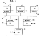
- a banking system which is designated generally as system 10, includes an entry processing unit (EPU) 12, a data entry processor (DEP) 14 with its associated image display terminals (IDT) 14-1, 14-2, and 14-3, and an encode and sort unit (ESU) 16 which are interconnected by a conventional, local-area network 18.
- EPU entry processing unit
- DEP data entry processor
- IDT image display terminals
- ESU encode and sort unit
- the function of the EPU 12 is to receive documents such as checks and deposit slips, for example, and mechanically read certain data from the documents which are processed in batches of about 200-300 documents per batch.
- the ESU 16 receives the completed data for a batch of documents from the DEP 14 and encodes the corresponding courtesy or monetary amount for a document on the associated document such as a check or deposit slip as it moves through the ESU 16. Certain other functions such as stamping, endorsing and microfilming are performed at the ESU 16 prior to having the documents sorted into various sorting pockets according to the bank's sorting instructions.
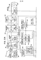
- the EPU 12 is shown in more detail in Figs. 2A and 2B, and has a general construction which is similar to a reader/sorter which is used to process documents such as checks and deposit slips, for example, in "batches" as previously described herein.
- a batch of such documents is placed in a stacker or hopper 20 (Fig. 2A), and a conventional feed mechanism 22 is used to pick a document 24 from the hopper 20, and thereafter a conventional transport mechanism 26 moves the document 24 along the document track 28 at a constant velocity and at a rate of 200 documents per minute in the embodiment described.
- a conventional hand-drop, feed mechanism 30 (Fig. 2A) is provided to enable individual documents 24 to be fed manually into the document track 28, when, for example, a document 24 jumps out of the track 28 and has to be fed again into the document track 28.
- MICR magnetic ink character recognition
- the MICR reader 32 is positioned along the track 28 so as to read the MICR line 34 (Fig. 5) on the document 24 as the document 24 is moved thereby.
- the MICR line 34 contains, for example, the identification of the associated bank number (transit routing number), customer's account number, check number, and other coding numbers which provide information as to the type of document, i.e. whether it is a check, deposit slip, etc., the size of the document, where the courtesy or monetary amount is located, etc.
- the output of the MICR reader 32 is fed into conventional recognition circuitry 36 which interprets the data read.
- sensors such as 38 and 40, for example, which are positioned along the track 28 (Fig. 2A) to check on the status of each of the documents as it is moved along the track 28.
- the sensors 38 and 40 are coupled to a conventional controller 42 which may include a microprocessor (not shown) to perform the routine tasks associated with moving documents along the track, -such tasks as controlling the feed mechanism 22 and the transport mechanism 26, for.example.
- the controller 42 is coupled to the EPU'processor 44 (Fig. 2B) via the interface 46.
- the EPU processor 44 receives this notification from the controller. 42 as just described, and the EPU processor 44 assigns a document reference number (DRN) to the data associated with the document 24 to be read by the MICR reader 32.
- DRN document reference number
- This DRN is unique for each document and will be used by the system 10 to identify the various data associated with a document 24 and to facilitate the processing of the documents in the system 10.
- the MICR data from the MICR reader 32 is processed by the recognition circuitry 36. Typical MICR data such as bank number, customer account number, and check number, for example, coming from the recognition circuitry 36 pass through the interface 48 to the random access memory (RAM) 50 of the EPU processor 44 where it is stored therein according to the now-available DRN.
- RAM random access memory
- the document 24 includes additional data on the MICR line 34 (Fig. 5) to facilitate the processing of documents within the system 10.
- This additional data may include, for example, a document-type number which indicates whether the document is a check, deposit slip, etc.; a size number which indicates the physical size of the document; a courtesy amount recognition (C.A.R.) type number which indicates whether the courtesy or monetary amount on the document is machine printed or hand written; a location number which indicates the location on the document of the courtesy amount which is shown at 52 in Fig. 5; and the height of the document.
- C.A.R. courtesy amount recognition
- This additional data is read by the recognition circuitry 36 and arranged or classified by the classifier circuitry 54 which forwards this additional data via the interface 56 to the RAM 50 where it is stored by the associated DRN. As of this moment in the process being explained, the DRN is not printed on the associated document 24.
- a document 24 is read by the MICR reader 32, it is moved into operative relationship with a conventional imaging device 58 (Fig. 2A) which is positioned along the document track 28.
- the imaging device 58 may be conventional and is shown in more detail in Fig. 6.
- the imaging device 58 includes a transparent, glass window 60 which is positioned on a sidewall 28-1 of the document track 28 to enable light from the light sources 62 and 64 to be directed by the associated light guides 66 and 68, respectively, on to a scanning line-70.
- the scanning line 70 is shown as a point in Fig. 6, which represents a top or plan view of the track 28, as does Fig. 2A.
- the top, long edge of the document 24 is viewed in Fig. 6, and in normal operation, the document is moved on its lower, long edge, with the front of the document 24 facing the imaging device 58 as it is moved past it; the scanning line 70 in this environment is oriented in a vertical direction.
- the right-most edge of the document 24 (as viewed in Fig. 6) is illuminated by the sources of light 62 and 64, and light reflected therefrom through the window 60 is focused by a suitable lens system 72 on to the imaging sensor array 74.
- the array 74 may be of a type which produces a fixed number of picture elements or pixels along the scanning line 70.
- One such array 74 such as RL-1024B which is manufactured by Reticon Corporation, for example, produces 1024 pixels along the scanning line 70, although only 640 pixels are utilized to meet the resolution requirements of the embodiment described herein.
- each pixel from the sensor array 74 has an associated analog, gray-scale value which is converted or digitized by the processing circuitry 78 to produce, for example, a six bit byte of data for each pixel, thereby recording 64 shades of gray ranging from white to black.
- the 64 shades of gray may be reduced, for example, to two shades, i.e., either black or white, by the processing circuitry 78.
- a stream of bytes or bits of data is issued from the processing circuitry 78. Because this aspect is conventional, it need not be described in any further detail.
- the stream of data or pixels from the scanning line 70 (Fig. 6) of the "image" of a document 24 is further processed by having the output of the processing circuitry 78 fed into an enhancer 80 (Fig. 2A), whose output, in turn, is fed into a compressor 82.
- the enhancer 80 is conventional and is a circuit which is used to eliminate unnecessary background information and to make the pertinent data stand out from background information, for example,
- the compressor 82 is a conventional circuit which receives the enhanced data from the enhancer 80 and eliminates that data which is "meaningless” or “redundant” and thereby “compresses" the remaining data to produce compressed, digitized-image data which reduces the amount of transmission time necessary to transmit the data associated with an image of a document 24 and which also reduces memory storage requirements.
- the output of the compressor 82 is fed via a conventional interface 84 to the RAM 50 of the EPU processor 44, where this image data associated with a document 24 is stored temporarily by its associated DRN.
- a second imaging device and associated circuitry may be used to image the rear of a document 24 as described herein.
- the EPU processor 44 (Fig. 2B) includes the interfaces 48, 56, and 84 already mentioned, a read only memory (ROM) 86, the RAM 50, a display such as a cathode ray tube (CRT) 88, a keyboard (KB) 90, a processor (MP) 92 and interface and control logic 94.
- the processing routines associated with the EPU processor 44 may reside in the ROM 86; however, the routines are loaded, more typically in the RAM 50 from disc or tape storage (not shown), for example, as part of a conventional start-up procedure.
- the CRT 88 is used to provide communication with an operator who uses the keyboard 90 to enter data or instructions.
- the interface and control logic 94 provides the interconnections among the various components of the processor 44 to enable it to function, conventionally, as an "intelligent" application processor.
- the form of the processor 44 shown in Fig. 2B is utilized to portray the various functions performed thereby, and the actual form of the processor 44 may be different.
- a document 24 passes the imaging device 58 (Fig. 2A), it is moved into operative relationship with a conventional printer 96 which prints the DRN on the front of the associated document.
- the DRN was assigned earlier by the EPU processor 44 which transmits this DRN to the printer 96 via the interface 98.
- Various other conventional elements such as an endorser 100 i microfilmer 102, and microfilmer 104 are positioned along the track 28 in operative relationship with each document 24 passing by them.
- the endorser 100 may be used also to stamp a "logo" on the back of a document.
- microfilmer 102 takes a picture of the front of a document for a permanent record, and similarly, microfilmer 104 takes a picture of the rear of a document.
- the endorser 100, and microfilmers 102 and 104 are optional and are shown as being coupled to the EPU processor 44-via the interface 98 along with the DRN printer 96.
- the documents 24 are processed in a batch, as previously described, and after microfilming at microfilmers 102 and 104, they are diverted sequentially into a single pocket 106 by a diverter 108 which is controlled by a pocket controller 110 which is coupled to the EPU processor 44 via the interface 112. If the processor 44 wishes to single out one or more documents 24 (for various processing reasons) at this point, the processor 44 then sends out the appropriate instruction to the pocket controller 110 which causes the affected documents to be diverted into the reject pocket 114. As an optional feature, additional pockets like 106 may be provided to provide sorting capability to the EPU 12.
- the associated image data is processed, enhanced, and compressed as previously described, and the compressed, image data for each document is buffered in the RAM 50.
- the DRN associated with the compressed image data is combined therewith, and this compressed, image data is immediately transferred out of the EPU processor 44 via its interface 116 over the network 18 to the DEP 14 (Fig. 3) via its interface 118.
- the DEP 14 then immediately transfers the compressed, image data via the interface 120 to an image disc file 122 where it is stored by the associated DRN. Because the documents 24 are processed in batches of about 200-300 per batch, for example, a batch header card may be used to identify each batch of documents being processed.
- the batch header card is the first document to be processed in the associated batch and a batch number associated with the header card may be used to identify the various document data associated with a batch of documents.
- the compressed, image data in the image disc file 122 may be arranged by DRN within a batch number to facilitate the accessing thereof.
- the image data derived from the imaging device 58 (Fig. 2A) is also utilized to perform machine character recognition to ascertain the courtesy amount on the documents 24 being processed.
- the image data coming from the enhancer 80 (prior to compression) is fed into a courtesy amount recognition (C.A.R.) module 124 where this function is performed.
- C.A.R. courtesy amount recognition
- the classifier circuitry 54 provides certain data about each document, data such as document type, height, and size, location of the courtesy amount, and whether the courtesy amount is machine or handwritten, for example; for ease of discussion, this data shall be referred to hereinafter as C.A.R. type data.
- the C.A.R. type data as developed was stored in the RAM 50 of the EPU processor 44 (Fig. 2A) along with the DRN which was assigned to the associated document 24.
- a sensor such as 40, positioned along the document track 28, produces a signal to indicate the start of data for the document 24 approaching the imaging device 58, and this signal is used by the processor 44 to forward the C.A.R. type data along with the DRN to the C.A.R. module 124 via the interface 126.
- the C.A.R. type module 124 may be conventional and includes the necessary data buffers to store the data received and the processors and associated circuitry to effect character recognition. Some typical character recognition circuits and techniques are shown in U.S. Patents 3,603,390; 3,629,829; 3,878,509; and 3,882,463. It should be recalled that the imaging device 58, in effect, produces a matrix of binary data with 640 pixels of data being included in each scan as the document 24 is moved past the imaging device 58.
- the C.A.R. type data is used by the C.A.R. module 124 to facilitate the location, for example, of the matrix of data associated with the courtesy amount.
- module 124 then reads the courtesy amount using the image data received from the enhancer 80 and outputs the courtesy amount read to the EPU processor 44 via the interface 128 and stores the data momentarily in the RAM 50 by the DRN.
- the EPU processor 44 For each individual number of the cour - tesy amount read, there is an associated number developed to indicate the confidence level associated with that number read. For example, a number 9 may be used to indicate a high probability of correctness of reading, while the number 1 may indicate a low probability of correctness. A low probability of correctness may be used in subsequent processing in the system 10 to facilitate the location of errors if errors develop in the usual reconciliation process.
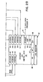
- the DEP 14 (Fig. 3) and its associated image display terminals (IDT) 14-1, 14-2, and 14-3, basically, effect further data completion and are used also for reconciliation and other banking operations.
- the DEP 14 may be similar to the EPU processor 44 and includes a keyboard 132, a processor MP 134 and a CRT 136 which function as previously explained, and the associated programs or instructions may be stored in the ROM 138 or the RAM 140, also, as previously explained.
- the interface and control logic 142 provides the interconnections among the various elements shown.
- the IDTs 14-1, 14-2, and 14-3 (Fig. 3) are all basically alike except for certain operating instructions, and consequently, a detailed description of only IDT 14-1 will be given.
- the IDT 14-1 may be conventional and includes a keyboard 144, processor 146, RAM 148, ROM 150, decompressor 152, interface 118-1, a CRT 156, and interface and control logic 158 which are all conventionally interconnected to enable the IDT 14-1 to function as what is considered an "intelligent" terminal.
- the IDT 14-1 in the embodiment described, is used primarily for courtesy amount entry by an operator; the IDT 14-2 is used primarily for. correction of MICR data; and the. IDT 14-3 is used for reconciliation procedures.- Naturally, while the terminals 14-1, 14-2, and 14-3 are basically alike, their associated operating instructions (stored in the ROM 150 or RAM 148) are different to reflect the various general functions described.
- the decompressor 152 decompresses the compressed image data for a document (from the image disc file.122) to enable.the image of the documents to be viewed on the CRT 156 to facilitate data completion.
- the DEP 14 examines the data on the MICR disc file 130 for a batch of documents to determine which of the documents, if any, in that batch require further data completion.
- the various tags indicating incomplete data or courtesy amounts having low confidence levels as previously described are used to access the data for each such document from the MICR disc file 130 via the interface 131.
- the confidence level takes the form of "recognition distances", for example. By this technique, a recognition distance close to zero means that the particular character read conforms to a matching "template" for that character. A large recognition distance means that the character read does not conform to one of the character templates anticipated.
- the corresponding image data from the image disc file 122 is selected by its DRN, and the image data and the data from MICR disc file 130 are forwarded to the appropriate IDT 14-1, 14-2, or 14-3, as previously described.
- the image data from disc file 122 and the data from the disc file 130 are forwarded to the IDT 14-1 via the interface 18-1 of DEP 14 and interface 118-1 of IDT 14-1.
- the IDT 14-1 then decompresses the image data via the decompressor 152 and displays the image of the front of the document on the CRT 156.
- the operator then reads the courtesy amount from the image of the document 24 and enters the amount on the keyboard 144.
- the operator actuates a transfer key on the keyboard 144 to transfer the courtesy amount and other data completed to the DEP 14.
- the DEP 14 has process routines residing in the ROM 138 or RAM 140 which transfer the now-completed data for the document 24 into the MICR disc file 130 by DRN and the affected tags associated with the data are changed to reflect the completion of data.
- data for more than one document 24 may be transferred from the DEP 14 to the IDT 14-1 where it is stored in the RAM 148 to facilitate the completion of data by the operator of the IDT 14-1 through such techniques as pre-viewing, for example.
- the operator at a terminal like terminal 14-1 is provided with an image on the CRT 156 of the document being processed, and in addition, is provided with the image of the next document to be processed, to thereby enable the operator to "pre-view” it while the data for the document just completed is "put away” or transferred to the appropriate destination.
- This process of obtaining the courtesy amount is repeated for all the documents 24 in a batch which are deficient in this respect.
- the process of completing the MICR data derived from the MICR reader 32 in Fig. 2A is effected on the IDT 14-2 (Fig. 3) in a manner similar to that already explained with regard to completing the courtesy amount on the IDT 14-1. Because of the folding of documents or of dirt on the MICR line 34 of documents, for example, the MICR line of data for a document may have one or more characters or numbers missing.
- This data is completed on the IDT 14-2 by having the associated image data from the image disc file 122 and the associated data from MICR disc file 130 transferred from the DEP 14 to the IDT 14-2 via interfaces 18-2 and 118-2.
- the MICR data is completed by viewing the image data on the CRT 156-2 and by entering the data needed on the keyboard 144-2.
- the completed data for each document is then transferred to MICR disc file 130 to complete the data stored thereat. This process is repeated for each document 24 having incomplete MICR data in the associated batch.
- an operator at the IDT 14-3 may request the image data from file 122 and the MICR data from file 130 for those documents which had low confidence levels for the courtesy amounts read from the C.A.R. module 124 (Fig. 2A). This data is forwarded from the DEP 14 to the IDT 14-3 via the interfaces 18-3 and 118-3 as previously described. The images for these checks are viewed on the C R T 156-3, and the operator makes data changes on the keyboard 144-3 for those errors found. The corrected data for the associated checks is transferred to the MICR disc file 130 and the reconciliation process is completed. Listings and other banking operations may be effected from the completed and corrected data in disc file 130.
- the DEP 14 and its associated terminals like 14-1, 14-2, and 14-3 are used to further complete the obtaining of data and to effect reconciliation on the batches of documents.
- the completed data from the MICR disc file 130 (Fig. 3) is transferred over the network 18 to the ESU 16 when the processing thereat is to be performed.
- the interfaces 118-1, 118-2, and 118-3 for the IDTs 14-1; 14-2, and 14-3, respectively, are shown as being directly connected to interfaces within the DEP 14 to facilitate a showing theteof; however, in the embodiment described, the interfaces 118-1, 118-2, and 118-3 are coupled to the local area network 18 as shown in Fig. 1.
- batches of documents 24 are processed serially at the EPU 12, and further data completion is effected at the DEP 14.
- the physical documents 24' are moved to the ESU 16 where encoding the courtesy amount (in MICR ink), for example is effected, and the documents 24 are physically sorted according to the bank's predetermined criteria or sorting instructions.
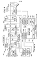
- the ESU 16 shown in Fig. 1 is shown in more detail in Fig. 4. Much of the physical structure of the ESU 16 is similar to a conventional reader/sorter unit; consequently, a detailed description of the physical structure thereof is not deemed necessary.
- a batch of documents to be processed, along with the associated batch header card, for example, are placed in the hopper 160 (Fig. 4).
- An operator at the ESU 16 requests data for the associated batch of documents by entering, for example, the particular batch number on the keyboard 162 of an encode and sort (E&S) processor 164 which controls the overall operation of the ESU 16.
- E&S encode and sort
- Several batches may be included in a "run", as is typically done.
- the E&S processor 164 (Fig. 4) has its operating instructions stored in either-the ROM 166 or RAM 168, as previously described with the other processors herein.
- a CRT 170 is used to communicate with an o p er- ator, and a processor MP 172 is used to execute the operating instructions.
- Suitable interface and control logic 174 is used to interconnect the various elements described and the interfaces to be described to enable the E&S processor 164 to function as an intelligent terminal.
- the associated completed data which is stored in the MICR disc file 130 (Fig. 3) is transferred over the network 18 to the interface 176 of the E&S processor 164 to be stored in its RAM 168.
- the completed data for each document in a batch from file 130 appears in the same order as the corresponding documents 24 in the batch which is loaded in the hopper 160.
- the first document 24 is picked from the hopper 160 by a conventional feed mechanism 178, and a conventional transport mechanism 180 moves the document 24 along the document track 182 at a constant velocity.
- the feed and transport mechanisms 178 and 180 are under the control of a conventional controller 184 which is interfaced with the E&S processor 164 by an interface 186.
- the controller 184 performs the usual operations of feeding and of checking on the progress of the documents 24 as they are moved along the track 182.
- Document sensors such as sensors 190 and 192, for example, which are operatively coupled to the controller 184, are used for this progress checking.
- a conventional hand drop 200 is provided to enable an operator to manually load a document 24 into the track 182.
- the ESU 16 (Fig. 4) also has a MICR reader 202, positioned along the track 182 to be in operative, reading relationship with the documents 24 as they are moved thereby.
- the reader 202 reads the MICR line 34 of data on the documents 24, and this line of data is interpreted by the conventional recognition circuitry 204.
- a conventional, matching circuit 206 receives the output of the recognition circuitry 204, and also receives (via interface 208) at least a portion of the "MICR data" for the first document which was stored in the RAM 168, and the circuit 206 makes a comparison of the data received.
- the documents 24 in the batch should be in the same order as they were in when processed at the EPU 12; however, this matching operation provides a way of detecting documents which are missing or out of order, for example.
- the associated document 24 is moved along the document track 182 and approaches the encoder 210.
- the encoder 210 is conventional, and in the embodiment described, it prints or encodes the courtesy amount, for example, for that document in MICR ink on the document itself when a match occurs at the matching circuit 206; this is the most typical situation. If a match does not occur, the E&S processor 164 will issue an appropriate signal (via its interface 212) to the pocket controller 214 which directs the diverting mechanism 216 to divert the associated document 24 into pocket 194, which may be considered the reject pocket. When a match occurs, the appropriate data including the courtesy amount for a document 24 which was obtained from the MICR disc file 130 (Fig.
- the encoder 210 may have its own feed mechanism (not shown) associated therewith to enable the document 24 to be moved in printing relationship with the encoder 210; this is due to the fact that the feed rate effected by the transport mechanism 180 is generally different from that required by the encoder 210.
- the document is moved further downstream along the document track 182 where a stamper 220 and an endorser 222 are used, conventionally, to stamp and endorse the documents according to customer specifications, with the appropriate data or controls therefor being supplied from the E&S processor 164 via the interface 224.
- a stamper 220 and an endorser 222 are used, conventionally, to stamp and endorse the documents according to customer specifications, with the appropriate data or controls therefor being supplied from the E&S processor 164 via the interface 224.
- conventional microfilming units 226 and 228, positioned along the document track 182, are used to microfilm, respectively, the front and back of a document 24. These units 226 and 228 are under the control of the E&S processor 164, and are coupled thereto via the interface 230.
- the instructions for sorting the documents 24 into the pockets like 194, 196, and 198 reside in either the ROM 166 or the RAM 168 and are prepared according to predetermined criteria and customer's instructions.
- the data which is used for sorting the documents is that which was derived and stored in the MICR disc file 130 (and transferred to RAM 168) rather than that MICR data which was read by MICR reader 202 from the document itself.
- the process just described at the ESU 16 is repeated for each of the batches of documents -to be processed as soon as the processing is completed at the DEP 14 as previously described.
Abstract
Description
- This invention relates to an apparatus and method for processing documents in which machine-readable data is read from a document as it is moved along a track in operative relationship with a reading means.
- The invention has application, for example, to the processing of documents such as checks which are used currently in banking systems and which have certain data such as individual account numbers, bank routing numbers etc., printed thereon in magnetic ink; such data is commonly referred to as magnetic ink character recognition or MICR data. When a document is received at a bank for processing, the monetary amount of the document is written, for example, by a customer in plain or non-magnetic ink. Part of the routine processing of a document such as a check requires that the monetary amount of the check be printed thereon in magnetic ink, thereby making it part of the MICR data on the check to be used for subsequent mechanical processing.
- Generally, such typical documents including checks are processed in "batches" including about 200-300 documents in each batch. Certain accounting or banking operations are performed on a "batch" of such documents.
- In U.S. Patent No. 4205780 there is disclosed a document processing system in which documents to be processed are moved sequentially past a machine-readable data reader and a video camera. The data reader reads and stores in a digital memory the machine readable data encoded on the documents, and the video camera captures the entire image of each document and stores the images in a video memory. The system also includes a plurality of video terminals at which the operators of the system can recall and display on command both the machine readable data and the video images of the documents. During a document processing operation, the operators at the video terminals read the monetary amount of each check from the video terminals and enter these amounts into the digital memory via keyboards. After the documents have been processed at the video terminals, the checks are run through an MICR encoder which encodes each check with the appropriate monetary amount. However, this known system has the disadvantage that the monetary amount of every check has to be manually entered by an operator into the digital memory prior to this amount being encoded on the check, and as a result the system is slow in operation and there are high operating costs.
- It is an object of the present invention to provide a document processing apparatus and method which enable rapid processing of documents to be achieved in a cost effective manner.
- According to one aspect of the invention, there is provided an apparatus for processing documents, including: reading means for reading machine-readable data, and imaging means for generating image data, from said documents as said documents are moved along a track in operative relationship with said reading means and said imaging means, characterized by recognition means arranged to receive said image data and a portion of said machine-readable data and to produce recognition data representative of predetermined data forming part of said image data, along with confidence level data relative to said recognition data, for each document, and control.means operatively coupled to said recognition means for storing said machine-readable data, image data, recognition data, and confidence level data using a document reference number which is assigned to each document by/said control means.
- According to another aspect of the invention, there is provided a method of processing documents including the steps of: (a) moving a document along a track; (b) reading machine-readable data from said document as it is moved along said track; and (c) producing image data from said document as it is moved along said track; characterized by the step of (d) utilizing a portion of said machine-readable data in conjunction with said image data to facilitate machine recognizing of predetermined data forming part of said image data, and for producing confidence level data associated with said predetermined data.
- One embodiment of the present invention will now be described by way of example with reference to the accompanying drawings, in which:-
- Fig. 1 is a general schematic diagram, in block form, of a document processing system showing an entry processing unit (EPU), a data entry processor (DEP) with associated image display terminals (IDT), and an encode and sort unit (ESU), which are all interconnected by a local area network;
- Figs. 2A and 2B taken together form a schematic diagram, in block form, showing more details of the EPU shown in Fig. 1;
- Fig. 3 is a schematic diagram, in block form, showing more details of the DEP and its associated terminals shown in Fig. 1;
- Fig. 4 is a schematic diagram, in block form, showing more details of the ESU shown in Fig. 1;
- Fig. 5 shows an example of a document which is processed by the system shown in Fig. 1; and
- Fig. 6 is a plan view showing more details of the imaging device shown in Fig. 2A.
- Referring to Fig. 1, a banking system, which is designated generally as
system 10, includes an entry processing unit (EPU) 12, a data entry processor (DEP) 14 with its associated image display terminals (IDT) 14-1, 14-2, and 14-3, and an encode and sort unit (ESU) 16 which are interconnected by a conventional, local-area network 18. - In general, the function of the
EPU 12 is to receive documents such as checks and deposit slips, for example, and mechanically read certain data from the documents which are processed in batches of about 200-300 documents per batch. TheDEP 14, along with the IDTs 14-1, 14-2, and 14-3, in general, perform the function of using the output of the EPU and completing the data not mechanically read at theEPU 12, correcting mis-read data where necessary, and performing certain banking procedures such as proof and reconciliation, for example. The ESU 16, in general, receives the completed data for a batch of documents from theDEP 14 and encodes the corresponding courtesy or monetary amount for a document on the associated document such as a check or deposit slip as it moves through theESU 16. Certain other functions such as stamping, endorsing and microfilming are performed at the ESU 16 prior to having the documents sorted into various sorting pockets according to the bank's sorting instructions. - The
EPU 12 is shown in more detail in Figs. 2A and 2B, and has a general construction which is similar to a reader/sorter which is used to process documents such as checks and deposit slips, for example, in "batches" as previously described herein. - A batch of such documents is placed in a stacker or hopper 20 (Fig. 2A), and a
conventional feed mechanism 22 is used to pick adocument 24 from thehopper 20, and thereafter aconventional transport mechanism 26 moves thedocument 24 along thedocument track 28 at a constant velocity and at a rate of 200 documents per minute in the embodiment described. - A conventional hand-drop, feed mechanism 30 (Fig. 2A) is provided to enable
individual documents 24 to be fed manually into thedocument track 28, when, for example, adocument 24 jumps out of thetrack 28 and has to be fed again into thedocument track 28. - As each
document 24 is moved along thetrack 28, it is brought into operative, reading relationship with a conventional, magnetic ink character recognition (MICR)reader 32. TheMICR reader 32 is positioned along thetrack 28 so as to read the MICR line 34 (Fig. 5) on thedocument 24 as thedocument 24 is moved thereby. TheMICR line 34 contains, for example, the identification of the associated bank number (transit routing number), customer's account number, check number, and other coding numbers which provide information as to the type of document, i.e. whether it is a check, deposit slip, etc., the size of the document, where the courtesy or monetary amount is located, etc. The output of theMICR reader 32 is fed intoconventional recognition circuitry 36 which interprets the data read. - There are sensors such as 38 and 40, for example, which are positioned along the track 28 (Fig. 2A) to check on the status of each of the documents as it is moved along the
track 28. Thesensors conventional controller 42 which may include a microprocessor (not shown) to perform the routine tasks associated with moving documents along the track, -such tasks as controlling thefeed mechanism 22 and thetransport mechanism 26, for.example. Thecontroller 42 is coupled to the EPU'processor 44 (Fig. 2B) via theinterface 46. - Continuing with the example being described, when the sensor 38 (Fig. 2A) indicates that a
document 24 approaches theMICR reader 32, theEPU processor 44 receives this notification from the controller. 42 as just described, and theEPU processor 44 assigns a document reference number (DRN) to the data associated with thedocument 24 to be read by theMICR reader 32. This DRN is unique for each document and will be used by thesystem 10 to identify the various data associated with adocument 24 and to facilitate the processing of the documents in thesystem 10. The MICR data from theMICR reader 32 is processed by therecognition circuitry 36. Typical MICR data such as bank number, customer account number, and check number, for example, coming from therecognition circuitry 36 pass through theinterface 48 to the random access memory (RAM) 50 of theEPU processor 44 where it is stored therein according to the now-available DRN. - The
document 24 includes additional data on the MICR line 34 (Fig. 5) to facilitate the processing of documents within thesystem 10. This additional data, determined by the financial institution or bank which supplies thedocuments 24 and uses thesystem 10, may include, for example, a document-type number which indicates whether the document is a check, deposit slip, etc.; a size number which indicates the physical size of the document; a courtesy amount recognition (C.A.R.) type number which indicates whether the courtesy or monetary amount on the document is machine printed or hand written; a location number which indicates the location on the document of the courtesy amount which is shown at 52 in Fig. 5; and the height of the document. This additional data is read by therecognition circuitry 36 and arranged or classified by theclassifier circuitry 54 which forwards this additional data via theinterface 56 to theRAM 50 where it is stored by the associated DRN. As of this moment in the process being explained, the DRN is not printed on theassociated document 24. - After a
document 24 is read by theMICR reader 32, it is moved into operative relationship with a conventional imaging device 58 (Fig. 2A) which is positioned along thedocument track 28. - The
imaging device 58 may be conventional and is shown in more detail in Fig. 6. Theimaging device 58 includes a transparent,glass window 60 which is positioned on a sidewall 28-1 of thedocument track 28 to enable light from thelight sources light guides scanning line 70 is shown as a point in Fig. 6, which represents a top or plan view of thetrack 28, as does Fig. 2A. The top, long edge of thedocument 24 is viewed in Fig. 6, and in normal operation, the document is moved on its lower, long edge, with the front of thedocument 24 facing theimaging device 58 as it is moved past it; thescanning line 70 in this environment is oriented in a vertical direction. As adocument 24 is moved past thescanning line 70, the right-most edge of the document 24 (as viewed in Fig. 6) is illuminated by the sources oflight window 60 is focused by asuitable lens system 72 on to theimaging sensor array 74. In the embodiment described, thearray 74 may be of a type which produces a fixed number of picture elements or pixels along thescanning line 70. Onesuch array 74, such as RL-1024B which is manufactured by Reticon Corporation, for example, produces 1024 pixels along thescanning line 70, although only 640 pixels are utilized to meet the resolution requirements of the embodiment described herein. As thedocument 24 is moved in the downstream direction shown byarrow 76, a new area of the document is presented to thescanning line 70 which produces a new set of 640 pixels therealong. Each pixel from thesensor array 74 has an associated analog, gray-scale value which is converted or digitized by theprocessing circuitry 78 to produce, for example, a six bit byte of data for each pixel, thereby recording 64 shades of gray ranging from white to black. The 64 shades of gray may be reduced, for example, to two shades, i.e., either black or white, by theprocessing circuitry 78. As the scans are completed, a stream of bytes or bits of data is issued from theprocessing circuitry 78. Because this aspect is conventional, it need not be described in any further detail. - The stream of data or pixels from the scanning line 70 (Fig. 6) of the "image" of a
document 24 is further processed by having the output of theprocessing circuitry 78 fed into an enhancer 80 (Fig. 2A), whose output, in turn, is fed into acompressor 82. Theenhancer 80 is conventional and is a circuit which is used to eliminate unnecessary background information and to make the pertinent data stand out from background information, for example, Thecompressor 82 is a conventional circuit which receives the enhanced data from theenhancer 80 and eliminates that data which is "meaningless" or "redundant" and thereby "compresses" the remaining data to produce compressed, digitized-image data which reduces the amount of transmission time necessary to transmit the data associated with an image of adocument 24 and which also reduces memory storage requirements. The output of thecompressor 82 is fed via aconventional interface 84 to theRAM 50 of theEPU processor 44, where this image data associated with adocument 24 is stored temporarily by its associated DRN. As an optional feature, a second imaging device and associated circuitry (not shown) may be used to image the rear of adocument 24 as described herein. - The EPU processor 44 (Fig. 2B) includes the
interfaces RAM 50, a display such as a cathode ray tube (CRT) 88, a keyboard (KB) 90, a processor (MP) 92 and interface and controllogic 94. The processing routines associated with theEPU processor 44 may reside in theROM 86; however, the routines are loaded, more typically in theRAM 50 from disc or tape storage (not shown), for example, as part of a conventional start-up procedure. TheCRT 88 is used to provide communication with an operator who uses thekeyboard 90 to enter data or instructions. The interface and controllogic 94 provides the interconnections among the various components of theprocessor 44 to enable it to function, conventionally, as an "intelligent" application processor. The form of theprocessor 44 shown in Fig. 2B is utilized to portray the various functions performed thereby, and the actual form of theprocessor 44 may be different. - Continuing with the movement of a
document 24 along thedocument track 28, after adocument 24 passes the imaging device 58 (Fig. 2A), it is moved into operative relationship with aconventional printer 96 which prints the DRN on the front of the associated document. The DRN was assigned earlier by theEPU processor 44 which transmits this DRN to theprinter 96 via theinterface 98. Various other conventional elements such as anendorser 100imicrofilmer 102, andmicrofilmer 104 are positioned along thetrack 28 in operative relationship with eachdocument 24 passing by them. Theendorser 100 may be used also to stamp a "logo" on the back of a document. Themicrofilmer 102 takes a picture of the front of a document for a permanent record, and similarly,microfilmer 104 takes a picture of the rear of a document. Theendorser 100, and microfilmers 102 and 104 are optional and are shown as being coupled to the EPU processor 44-via theinterface 98 along with theDRN printer 96. - Normally, the
documents 24 are processed in a batch, as previously described, and after microfilming atmicrofilmers single pocket 106 by adiverter 108 which is controlled by apocket controller 110 which is coupled to theEPU processor 44 via theinterface 112. If theprocessor 44 wishes to single out one or more documents 24 (for various processing reasons) at this point, theprocessor 44 then sends out the appropriate instruction to thepocket controller 110 which causes the affected documents to be diverted into the reject pocket 114. As an optional feature, additional pockets like 106 may be provided to provide sorting capability to theEPU 12. - As the
documents 24 are moved, sequentially, past the imaging device 58 (Fig. 2A)-, the associated image data is processed, enhanced, and compressed as previously described, and the compressed, image data for each document is buffered in theRAM 50. The DRN associated with the compressed image data is combined therewith, and this compressed, image data is immediately transferred out of theEPU processor 44 via itsinterface 116 over thenetwork 18 to the DEP 14 (Fig. 3) via itsinterface 118. TheDEP 14 then immediately transfers the compressed, image data via theinterface 120 to animage disc file 122 where it is stored by the associated DRN. Because thedocuments 24 are processed in batches of about 200-300 per batch, for example, a batch header card may be used to identify each batch of documents being processed. The batch header card is the first document to be processed in the associated batch and a batch number associated with the header card may be used to identify the various document data associated with a batch of documents. In this regard, the compressed, image data in theimage disc file 122 may be arranged by DRN within a batch number to facilitate the accessing thereof. - The image data derived from the imaging device 58 (Fig. 2A) is also utilized to perform machine character recognition to ascertain the courtesy amount on the
documents 24 being processed. The image data coming from the enhancer 80 (prior to compression) is fed into a courtesy amount recognition (C.A.R.)module 124 where this function is performed. It also should be recalled that theclassifier circuitry 54 provides certain data about each document, data such as document type, height, and size, location of the courtesy amount, and whether the courtesy amount is machine or handwritten, for example; for ease of discussion, this data shall be referred to hereinafter as C.A.R. type data. - The C.A.R. type data as developed was stored in the
RAM 50 of the EPU processor 44 (Fig. 2A) along with the DRN which was assigned to the associateddocument 24. A sensor such as 40, positioned along thedocument track 28, produces a signal to indicate the start of data for thedocument 24 approaching theimaging device 58, and this signal is used by theprocessor 44 to forward the C.A.R. type data along with the DRN to the C.A.R.module 124 via theinterface 126. - The C.A.R. type module 124 (Fig. 2A) may be conventional and includes the necessary data buffers to store the data received and the processors and associated circuitry to effect character recognition. Some typical character recognition circuits and techniques are shown in U.S. Patents 3,603,390; 3,629,829; 3,878,509; and 3,882,463. It should be recalled that the
imaging device 58, in effect, produces a matrix of binary data with 640 pixels of data being included in each scan as thedocument 24 is moved past theimaging device 58. The C.A.R. type data is used by the C.A.R.module 124 to facilitate the location, for example, of the matrix of data associated with the courtesy amount. The C.A.R.module 124 then reads the courtesy amount using the image data received from theenhancer 80 and outputs the courtesy amount read to theEPU processor 44 via theinterface 128 and stores the data momentarily in theRAM 50 by the DRN. For each individual number of the cour- tesy amount read, there is an associated number developed to indicate the confidence level associated with that number read. For example, a number 9 may be used to indicate a high probability of correctness of reading, while the number 1 may indicate a low probability of correctness. A low probability of correctness may be used in subsequent processing in thesystem 10 to facilitate the location of errors if errors develop in the usual reconciliation process. Naturally, a low probability of correctness of reading, or individual numbers of the monetary amount not being read at all would be tagged (with a 0, for example) to indicate the need for data completion at the DEP'14. The MICR data read from therecognition circuitry 36 and the courtesy amount along with the confidence level of each of the numbers in the courtesy amount are combined by DRN in theEPU processor 44. After combining, the data as completed is forwarded via theinterface 116 over thenetwork 18 to theDEP 14 via itsinterface 118, and thereafter, this data completed is transferred (via interface 131) and stored on a second storage ordisc file 130 by DRN within the associated batch number in the embodiment described. This process is repeated for all thedocuments 24 in a batch of documents being processed. - The DEP 14 (Fig. 3) and its associated image display terminals (IDT) 14-1, 14-2, and 14-3, basically, effect further data completion and are used also for reconciliation and other banking operations. The
DEP 14 may be similar to theEPU processor 44 and includes akeyboard 132, aprocessor MP 134 and aCRT 136 which function as previously explained, and the associated programs or instructions may be stored in theROM 138 or theRAM 140, also, as previously explained. The interface andcontrol logic 142 provides the interconnections among the various elements shown. - The IDTs 14-1, 14-2, and 14-3 (Fig. 3) are all basically alike except for certain operating instructions, and consequently, a detailed description of only IDT 14-1 will be given.
- The IDT 14-1 (Fig. 3) may be conventional and includes a
keyboard 144,processor 146,RAM 148,ROM 150,decompressor 152, interface 118-1, aCRT 156, and interface andcontrol logic 158 which are all conventionally interconnected to enable the IDT 14-1 to function as what is considered an "intelligent" terminal. The IDT 14-1, in the embodiment described, is used primarily for courtesy amount entry by an operator; the IDT 14-2 is used primarily for. correction of MICR data; and the. IDT 14-3 is used for reconciliation procedures.- Naturally, while the terminals 14-1, 14-2, and 14-3 are basically alike, their associated operating instructions (stored in theROM 150 or RAM 148) are different to reflect the various general functions described. Thedecompressor 152 decompresses the compressed image data for a document (from the image disc file.122) to enable.the image of the documents to be viewed on theCRT 156 to facilitate data completion. - As a first step in data completion at the
DEP 14, theDEP 14 examines the data on theMICR disc file 130 for a batch of documents to determine which of the documents, if any, in that batch require further data completion. In this regard, the various tags indicating incomplete data or courtesy amounts having low confidence levels as previously described are used to access the data for each such document from theMICR disc file 130 via theinterface 131. In one prior art, character- recognition technique, the confidence level takes the form of "recognition distances", for example. By this technique, a recognition distance close to zero means that the particular character read conforms to a matching "template" for that character. A large recognition distance means that the character read does not conform to one of the character templates anticipated. Continuing further, the corresponding image data from theimage disc file 122 is selected by its DRN, and the image data and the data fromMICR disc file 130 are forwarded to the appropriate IDT 14-1, 14-2, or 14-3, as previously described. For example, if the courtesy amount on adocument 24 is missing, the image data fromdisc file 122 and the data from thedisc file 130 are forwarded to the IDT 14-1 via the interface 18-1 ofDEP 14 and interface 118-1 of IDT 14-1. The IDT 14-1 then decompresses the image data via thedecompressor 152 and displays the image of the front of the document on theCRT 156. The operator then reads the courtesy amount from the image of thedocument 24 and enters the amount on thekeyboard 144. Upon completion of the operation, the operator actuates a transfer key on thekeyboard 144 to transfer the courtesy amount and other data completed to theDEP 14. TheDEP 14 has process routines residing in theROM 138 orRAM 140 which transfer the now-completed data for thedocument 24 into theMICR disc file 130 by DRN and the affected tags associated with the data are changed to reflect the completion of data. In general, data for more than onedocument 24 may be transferred from theDEP 14 to the IDT 14-1 where it is stored in theRAM 148 to facilitate the completion of data by the operator of the IDT 14-1 through such techniques as pre-viewing, for example. In pre-viewing, the operator at a terminal like terminal 14-1 is provided with an image on theCRT 156 of the document being processed, and in addition, is provided with the image of the next document to be processed, to thereby enable the operator to "pre-view" it while the data for the document just completed is "put away" or transferred to the appropriate destination. This process of obtaining the courtesy amount is repeated for all thedocuments 24 in a batch which are deficient in this respect. - The process of completing the MICR data derived from the
MICR reader 32 in Fig. 2A is effected on the IDT 14-2 (Fig. 3) in a manner similar to that already explained with regard to completing the courtesy amount on the IDT 14-1. Because of the folding of documents or of dirt on theMICR line 34 of documents, for example, the MICR line of data for a document may have one or more characters or numbers missing. This data is completed on the IDT 14-2 by having the associated image data from theimage disc file 122 and the associated data fromMICR disc file 130 transferred from theDEP 14 to the IDT 14-2 via interfaces 18-2 and 118-2. The MICR data is completed by viewing the image data on the CRT 156-2 and by entering the data needed on the keyboard 144-2. The completed data for each document is then transferred toMICR disc file 130 to complete the data stored thereat. This process is repeated for eachdocument 24 having incomplete MICR data in the associated batch. - After the courtesy amount data and MICR data are completed for a batch of documents and stored in the MICR disc file 130 (Fig. 3), typical reconciliation processes in which debits equal credits, for example, along with other banking operations are performed on the IDT 14-3. For example, if a batch of
documents 24 includes only checks, a manual tally or total of the courtesy amounts of all the checks for that batch may be provided on the associated batch header card. Because the courtesy amounts for all the checks for this batch are present in theMICR disc file 130, an operator at IDT 14-3 may request, for example, that theDEP 14 perform the tally using the data in thefile 130. If the tally generated for a batch of documents from thefile 130 equals the total present on the associated batch header document, then the batch is in balance and no reconciliation is necessary. If these tally and total amounts differ, a reconciliation process is necessary to find the difference or error. In this regard an operator at the IDT 14-3 may request the image data fromfile 122 and the MICR data fromfile 130 for those documents which had low confidence levels for the courtesy amounts read from the C.A.R. module 124 (Fig. 2A). This data is forwarded from theDEP 14 to the IDT 14-3 via the interfaces 18-3 and 118-3 as previously described. The images for these checks are viewed on the CRT 156-3, and the operator makes data changes on the keyboard 144-3 for those errors found. The corrected data for the associated checks is transferred to theMICR disc file 130 and the reconciliation process is completed. Listings and other banking operations may be effected from the completed and corrected data indisc file 130. - To review, the
DEP 14 and its associated terminals like 14-1, 14-2, and 14-3 are used to further complete the obtaining of data and to effect reconciliation on the batches of documents. The completed data from the MICR disc file 130 (Fig. 3) is transferred over thenetwork 18 to theESU 16 when the processing thereat is to be performed. The interfaces 118-1, 118-2, and 118-3 for the IDTs 14-1; 14-2, and 14-3, respectively, are shown as being directly connected to interfaces within theDEP 14 to facilitate a showing theteof; however, in the embodiment described, the interfaces 118-1, 118-2, and 118-3 are coupled to thelocal area network 18 as shown in Fig. 1. - To summarize, batches of
documents 24 are processed serially at theEPU 12, and further data completion is effected at theDEP 14. When a batch ofdocuments 24 has its associated data completed and reconciled, for example, at theDEP 14, the physical documents 24'are moved to theESU 16 where encoding the courtesy amount (in MICR ink), for example is effected, and thedocuments 24 are physically sorted according to the bank's predetermined criteria or sorting instructions. - The
ESU 16, shown in Fig. 1, is shown in more detail in Fig. 4. Much of the physical structure of theESU 16 is similar to a conventional reader/sorter unit; consequently, a detailed description of the physical structure thereof is not deemed necessary. - A batch of documents to be processed, along with the associated batch header card, for example, are placed in the hopper 160 (Fig. 4). An operator at the
ESU 16 then requests data for the associated batch of documents by entering, for example, the particular batch number on thekeyboard 162 of an encode and sort (E&S)processor 164 which controls the overall operation of theESU 16. Several batches may be included in a "run", as is typically done. - The E&S processor 164 (Fig. 4) has its operating instructions stored in either-the
ROM 166 orRAM 168, as previously described with the other processors herein. ACRT 170 is used to communicate with an oper- ator, and aprocessor MP 172 is used to execute the operating instructions. Suitable interface andcontrol logic 174 is used to interconnect the various elements described and the interfaces to be described to enable theE&S processor 164 to function as an intelligent terminal. - When an operator requests the completed data for a batch of
documents 24 which are physically loaded in the hopper 160 (Fig. 4), the associated completed data which is stored in the MICR disc file 130 (Fig. 3) is transferred over thenetwork 18 to theinterface 176 of theE&S processor 164 to be stored in itsRAM 168. The completed data for each document in a batch fromfile 130 appears in the same order as the correspondingdocuments 24 in the batch which is loaded in thehopper 160. - Processing at the
ESU 16 is begun after the preparations discussed in the previous paragraph are made. In this regard, thefirst document 24 is picked from thehopper 160 by aconventional feed mechanism 178, and aconventional transport mechanism 180 moves thedocument 24 along thedocument track 182 at a constant velocity. The feed andtransport mechanisms conventional controller 184 which is interfaced with theE&S processor 164 by aninterface 186. Thecontroller 184 performs the usual operations of feeding and of checking on the progress of thedocuments 24 as they are moved along thetrack 182. Document sensors such assensors controller 184, are used for this progress checking. Aconventional merge hopper 193, under the control of thecontroller 184, is used to enable "document separators" to be automatically fed into thedocument track 182. These separators end up in the pockets like 194, 196, and 198 to provide for the separation ofdocuments 24 within the pockets, with only a few-pockets being shown in Fig. 4 to simplify the drawing. Aconventional hand drop 200 is provided to enable an operator to manually load adocument 24 into thetrack 182. - The ESU 16 (Fig. 4) also has a
MICR reader 202, positioned along thetrack 182 to be in operative, reading relationship with thedocuments 24 as they are moved thereby. Thereader 202 reads theMICR line 34 of data on thedocuments 24, and this line of data is interpreted by theconventional recognition circuitry 204. A conventional, matchingcircuit 206 receives the output of therecognition circuitry 204, and also receives (via interface 208) at least a portion of the "MICR data" for the first document which was stored in theRAM 168, and thecircuit 206 makes a comparison of the data received. Thedocuments 24 in the batch should be in the same order as they were in when processed at theEPU 12; however, this matching operation provides a way of detecting documents which are missing or out of order, for example. - As the matching operation is performed by the
matching circuit 206, the associateddocument 24 is moved along thedocument track 182 and approaches theencoder 210. Theencoder 210 is conventional, and in the embodiment described, it prints or encodes the courtesy amount, for example, for that document in MICR ink on the document itself when a match occurs at thematching circuit 206; this is the most typical situation. If a match does not occur, theE&S processor 164 will issue an appropriate signal (via its interface 212) to thepocket controller 214 which directs the divertingmechanism 216 to divert the associateddocument 24 intopocket 194, which may be considered the reject pocket. When a match occurs, the appropriate data including the courtesy amount for adocument 24 which was obtained from the MICR disc file 130 (Fig. 3) and stored in the RAM 168 (Fig. 4) is fed to theencoder 210, viainterface 218 where the data is-encoded on the document. Theencoder 210 may have its own feed mechanism (not shown) associated therewith to enable thedocument 24 to be moved in printing relationship with theencoder 210; this is due to the fact that the feed rate effected by thetransport mechanism 180 is generally different from that required by theencoder 210. - After the courtesy amount of the
document 24 is encoded on the document itself, the document is moved further downstream along thedocument track 182 where astamper 220 and anendorser 222 are used, conventionally, to stamp and endorse the documents according to customer specifications, with the appropriate data or controls therefor being supplied from theE&S processor 164 via theinterface 224. Optional,conventional microfilming units document track 182, are used to microfilm, respectively, the front and back of adocument 24. Theseunits E&S processor 164, and are coupled thereto via theinterface 230. - The instructions for sorting the
documents 24 into the pockets like 194, 196, and 198 reside in either theROM 166 or theRAM 168 and are prepared according to predetermined criteria and customer's instructions. The data which is used for sorting the documents is that which was derived and stored in the MICR disc file 130 (and transferred to RAM 168) rather than that MICR data which was read byMICR reader 202 from the document itself. The process just described at theESU 16 is repeated for each of the batches of documents -to be processed as soon as the processing is completed at theDEP 14 as previously described. - \Some of the advantages of the system described above are as follows:
- 1. An increased output of documents being processed is obtained.
- 2. Documents may continue to be processed in batches as is currently being done.
- 3. The apparatus and method of this invention are cost effective to implement, when compared to prior- art approaches.
- 4. Encoding of the documents is effected only after the data is correct from a proofing operation.
Claims (10)
Applications Claiming Priority (2)
| Application Number | Priority Date | Filing Date | Title |
|---|---|---|---|
| US452563 | 1982-12-23 | ||
| US06/452,563 US4523330A (en) | 1982-12-23 | 1982-12-23 | Banking system and method |
Publications (2)
| Publication Number | Publication Date |
|---|---|
| EP0115189A1 true EP0115189A1 (en) | 1984-08-08 |
| EP0115189B1 EP0115189B1 (en) | 1987-10-28 |
Family
ID=23796973
Family Applications (1)
| Application Number | Title | Priority Date | Filing Date |
|---|---|---|---|
| EP83307911A Expired EP0115189B1 (en) | 1982-12-23 | 1983-12-22 | Apparatus and method for processing documents |
Country Status (5)
| Country | Link |
|---|---|
| US (1) | US4523330A (en) |
| EP (1) | EP0115189B1 (en) |
| JP (1) | JPS59121571A (en) |
| CA (1) | CA1197621A (en) |
| DE (2) | DE115189T1 (en) |
Cited By (30)
| Publication number | Priority date | Publication date | Assignee | Title |
|---|---|---|---|---|
| EP0140527A2 (en) * | 1983-10-28 | 1985-05-08 | Unisys Corporation | Document reading system |
| FR2589267A1 (en) * | 1985-10-25 | 1987-04-30 | Bertin & Cie | IMAGE PROCESSING PROCESS, PARTICULARLY IN A POSTAL SORTING INSTALLATION |
| EP0281595A1 (en) * | 1986-08-20 | 1988-09-14 | Coulter Electronics Inc. | Automatic printing apparatus utilizing turnaround document |
| EP0344742A2 (en) * | 1988-05-31 | 1989-12-06 | Trw Financial Systems, Inc. | Courtesy amount read and transaction balancing system |
| AU601164B2 (en) * | 1985-11-12 | 1990-09-06 | Boehringer Ingelheim International Gmbh | Human lysozyme |
| FR2647925A1 (en) * | 1989-06-06 | 1990-12-07 | Chec Solutions | Device for linking between a processing unit for coded documents and a computer for driving the said unit and for checking the documents |
| EP0446633A2 (en) * | 1990-03-12 | 1991-09-18 | International Business Machines Corporation | Document processor including method and apparatus for identifying and correcting errors |
| FR2671414A1 (en) * | 1991-01-04 | 1992-07-10 | Dassault Electronique | Installation and method for processing transactions by documents of payment, such as cheques |
| WO1992016931A2 (en) * | 1991-03-15 | 1992-10-01 | Unisys Corporation | Archival document image processing and printing system |
| EP0511309A1 (en) * | 1990-01-16 | 1992-11-04 | Digital Image Systems Corp. | System for managing document entry and flow using data extracted by means of electronic imaging |
| EP0597430A1 (en) * | 1992-11-12 | 1994-05-18 | Laurel Bank Machines Co., Ltd. | Check book issuing machine |
| US5344132A (en) * | 1990-01-16 | 1994-09-06 | Digital Image Systems | Image based document processing and information management system and apparatus |
| FR2716987A1 (en) * | 1994-03-03 | 1995-09-08 | Dugast Jean Philippe | Computer system for assembling documents of different data types |
| EP0671696A1 (en) * | 1994-03-10 | 1995-09-13 | International Business Machines Corporation | High volume document image archive system and method |
| EP0793193A2 (en) * | 1996-03-01 | 1997-09-03 | FINMECCANICA S.p.A. | Automatic check reading device |
| EP0895868A2 (en) * | 1997-08-06 | 1999-02-10 | Seiko Epson Corporation | Method and apparatus for processing recording media having embedded information |
| US6055327A (en) * | 1997-07-17 | 2000-04-25 | Aragon; David Bradburn | Method of detecting data entry errors by sorting amounts and verifying amount order |
| DE19602136C2 (en) * | 1995-01-23 | 2001-08-09 | Ricoh Kk | Document processing system and method for processing a document |
| US6523927B2 (en) | 1997-08-06 | 2003-02-25 | Seiko Epson Corporation | Method and apparatus for processing recording media having embedded information |
| US6695427B2 (en) | 1997-08-06 | 2004-02-24 | Seiko Epson Corporation | Multifunction device and control method for the same |
| WO2006135698A1 (en) * | 2005-06-09 | 2006-12-21 | Bank Of America Corporation | Surrogate document indicator and methods of using same |
| WO2009049328A1 (en) * | 2007-10-09 | 2009-04-16 | Bank Of America Corporation | Ensuring image integrity using document characteristics |
| EP2078278A2 (en) * | 2006-10-26 | 2009-07-15 | Bank of America Corporation | Method and system for enhanced check image privacy |
| EP2219137A2 (en) | 2009-02-16 | 2010-08-18 | Seiko Epson Corporation | Recording device and control method for a recording device |
| US9823958B2 (en) | 2016-02-08 | 2017-11-21 | Bank Of America Corporation | System for processing data using different processing channels based on source error probability |
| US9952942B2 (en) | 2016-02-12 | 2018-04-24 | Bank Of America Corporation | System for distributed data processing with auto-recovery |
| US10067869B2 (en) | 2016-02-12 | 2018-09-04 | Bank Of America Corporation | System for distributed data processing with automatic caching at various system levels |
| US10437778B2 (en) | 2016-02-08 | 2019-10-08 | Bank Of America Corporation | Archive validation system with data purge triggering |
| US10437880B2 (en) | 2016-02-08 | 2019-10-08 | Bank Of America Corporation | Archive validation system with data purge triggering |
| US10460296B2 (en) | 2016-02-08 | 2019-10-29 | Bank Of America Corporation | System for processing data using parameters associated with the data for auto-processing |
Families Citing this family (194)
| Publication number | Priority date | Publication date | Assignee | Title |
|---|---|---|---|---|
| US4625275A (en) * | 1984-04-03 | 1986-11-25 | Republic Money Orders, Inc. | Apparatus for dispensing money orders |
| WO1986000441A1 (en) * | 1984-06-28 | 1986-01-16 | Scheurer William C | Electronic cash register terminal with automatic micr check amount encoder |
| US4817166A (en) * | 1986-05-05 | 1989-03-28 | Perceptics Corporation | Apparatus for reading a license plate |
| JPS62284468A (en) * | 1986-06-03 | 1987-12-10 | Fujitsu Ltd | Check processing system |
| US4813077A (en) * | 1986-07-30 | 1989-03-14 | Scan-Optics, Inc. | Sales transaction record processing system and method |
| US5097517A (en) * | 1987-03-17 | 1992-03-17 | Holt Arthur W | Method and apparatus for processing bank checks, drafts and like financial documents |
| US5208869A (en) * | 1986-09-19 | 1993-05-04 | Holt Arthur W | Character and pattern recognition machine and method |
| US5054092A (en) * | 1988-03-31 | 1991-10-01 | Checkmate Electronics, Inc. | Hand-operated low cost magnetic character recognition system |
| GB8802940D0 (en) * | 1988-02-09 | 1988-03-09 | Nally R B | Image qualification system |
| US5235652A (en) * | 1988-02-09 | 1993-08-10 | Nally Robert B | Qualification system for printed images |
| US5010238A (en) * | 1988-03-18 | 1991-04-23 | Hitachi, Ltd. | Automatic cash transaction system and method |
| US5265007A (en) * | 1988-06-07 | 1993-11-23 | Huntington Bancshares Incorporated | Central check clearing system |
| US5054096A (en) * | 1988-10-24 | 1991-10-01 | Empire Blue Cross/Blue Shield | Method and apparatus for converting documents into electronic data for transaction processing |
| US5081685A (en) * | 1988-11-29 | 1992-01-14 | Westinghouse Electric Corp. | Apparatus and method for reading a license plate |
| JPH02236664A (en) * | 1989-03-10 | 1990-09-19 | Fujitsu Ltd | Processor for note or check |
| US5237620A (en) * | 1989-05-01 | 1993-08-17 | Credit Verification Corporation | Check reader method and system for reading check MICR code |
| US6334108B1 (en) | 1989-05-01 | 2001-12-25 | Catalina Marketing International, Inc. | Method and system for selective incentive point-of-sale marketing in response to customer shopping histories |
| US5621812A (en) * | 1989-05-01 | 1997-04-15 | Credit Verification Corporation | Method and system for building a database for use with selective incentive marketing in response to customer shopping histories |
| US5649114A (en) | 1989-05-01 | 1997-07-15 | Credit Verification Corporation | Method and system for selective incentive point-of-sale marketing in response to customer shopping histories |
| US6684195B1 (en) | 1989-05-01 | 2004-01-27 | Catalina Marketing International, Inc. | Method and system for selective incentive point-of-sale marketing in response to customer shopping histories |
| US5201010A (en) * | 1989-05-01 | 1993-04-06 | Credit Verification Corporation | Method and system for building a database and performing marketing based upon prior shopping history |
| US8700458B2 (en) | 1989-05-01 | 2014-04-15 | Catalina Marketing Corporation | System, method, and database for processing transactions |
| US5305196A (en) * | 1989-05-01 | 1994-04-19 | Credit Verification Corporation | Check transaction processing, database building and marketing method and system utilizing automatic check reading |
| US5644723A (en) | 1989-05-01 | 1997-07-01 | Credit Verification Corporation | Method and system for selective incentive point-of-sale marketing in response to customer shopping histories |
| US5237158A (en) * | 1989-10-10 | 1993-08-17 | Unisys Corporation | Image-based document processing system providing for priority document shipment |
| US5120944A (en) * | 1989-10-10 | 1992-06-09 | Unisys Corp. | Image-based document processing system providing enhanced workstation balancing |
| US5708810A (en) * | 1989-10-10 | 1998-01-13 | Unisys Corporation | Image-based document processing system having a platform architecture |
| US5221830A (en) * | 1989-10-10 | 1993-06-22 | Unisys Corp. | Method of ordering displayed document images in an image based document processing system |
| US5206915A (en) * | 1989-10-10 | 1993-04-27 | Unisys Corporation | Image-based document processing system providing lost image recovery |
| US5349170A (en) * | 1989-10-10 | 1994-09-20 | Unisys Corporation | Image-based document processing system providing enhanced transaction balancing |
| US5134564A (en) * | 1989-10-19 | 1992-07-28 | Dunn Eric C W | Computer aided reconfiliation method and apparatus |
| US5198975A (en) * | 1989-11-30 | 1993-03-30 | Valley National Bank | Apparatus and method for processing of check batches in banking operations |
| US5040227A (en) * | 1990-03-12 | 1991-08-13 | International Business Machines Corporation | Image balancing system and method |
| US5077805A (en) * | 1990-05-07 | 1991-12-31 | Eastman Kodak Company | Hybrid feature-based and template matching optical character recognition system |
| US5721790A (en) * | 1990-10-19 | 1998-02-24 | Unisys Corporation | Methods and apparatus for separating integer and fractional portions of a financial amount |
| US5155643A (en) * | 1990-10-30 | 1992-10-13 | Mars Incorporated | Unshielded horizontal magnetoresistive head and method of fabricating same |
| US5187750A (en) * | 1991-03-15 | 1993-02-16 | Unisys Corporation | Archival document image processing and printing system |
| US5204811A (en) * | 1991-03-25 | 1993-04-20 | International Business Machines Corporation | Document processor with transport buffer |
| US5237159A (en) * | 1991-07-17 | 1993-08-17 | J. D. Carreker And Associates | Electronic check presentment system |
| US5691524A (en) * | 1991-07-17 | 1997-11-25 | J.D. Carreker And Associates, Inc. | Electronic check presentment system having a non-ECP exceptions notification system incorporated therein |
| US5783808A (en) * | 1996-01-11 | 1998-07-21 | J. D. Carreker And Associates, Inc. | Electronic check presentment system having transaction level reconciliation capability |
| US6179484B1 (en) | 1991-07-18 | 2001-01-30 | International Business Machines Corp. | Two-pass document image processing method and system |
| US5317654A (en) * | 1991-09-26 | 1994-05-31 | Inscerco Mfg. Inc. | Selective collating and inserting apparatus |
| US5378885A (en) * | 1991-10-29 | 1995-01-03 | Mars Incorporated | Unshielded magnetoresistive head with multiple pairs of sensing elements |
| US6292786B1 (en) | 1992-05-19 | 2001-09-18 | Incentech, Inc. | Method and system for generating incentives based on substantially real-time product purchase information |
| US5484988A (en) * | 1992-11-13 | 1996-01-16 | Resource Technology Services, Inc. | Checkwriting point of sale system |
| US5358088A (en) * | 1992-11-25 | 1994-10-25 | Mars Incorporated | Horizontal magnetoresistive head apparatus and method for detecting magnetic data |
| US5374999A (en) * | 1992-12-22 | 1994-12-20 | Silitek Corporation | Scan control system |
| GB9313640D0 (en) * | 1993-07-01 | 1993-08-18 | Ncr Int Inc | Document transaction apparatus |
| DE4322803C2 (en) * | 1993-07-08 | 1998-09-10 | Mohndruck Reinhard Mohn Ohg | Process for monitoring the completeness of individually printed products in online production |
| US5444794A (en) * | 1993-08-25 | 1995-08-22 | Sqn | Check image capture system |
| GB9323709D0 (en) * | 1993-11-15 | 1994-01-05 | Ncr Int Inc | Depository apparatus for envelopes and single sheets |
| US5774879A (en) * | 1993-12-27 | 1998-06-30 | First Data Corporation | Automated financial instrument processing system |
| US5740271A (en) * | 1994-07-27 | 1998-04-14 | On-Track Management System | Expenditure monitoring system |
| US5737440A (en) * | 1994-07-27 | 1998-04-07 | Kunkler; Todd M. | Method of detecting a mark on a oraphic icon |
| US5784503A (en) * | 1994-08-26 | 1998-07-21 | Unisys Corp | Check reader utilizing sync-tags to match the images at the front and rear faces of a check |
| CA2155891A1 (en) * | 1994-10-18 | 1996-04-19 | Raymond Amand Lorie | Optical character recognition system having context analyzer |
| US7152045B2 (en) * | 1994-11-28 | 2006-12-19 | Indivos Corporation | Tokenless identification system for authorization of electronic transactions and electronic transmissions |
| US6363164B1 (en) | 1996-05-13 | 2002-03-26 | Cummins-Allison Corp. | Automated document processing system using full image scanning |
| US5754673A (en) * | 1995-06-19 | 1998-05-19 | Ncr Corporation | Document image processing system including a first document path for the automated processing of documents and a second document path for the processing of documents requiring operator correction |
| US5689579A (en) * | 1996-01-17 | 1997-11-18 | J.D. Carreker And Associates, Inc. | Rule-based circuit, method and system for performing item level reconciliation |
| US6473519B1 (en) * | 1996-02-21 | 2002-10-29 | Hand Held Products, Inc. | Check reader |
| US5832463A (en) * | 1996-03-28 | 1998-11-03 | Electronic Data Systems Corporation | Automated system and method for checkless check transaction |
| US6059185A (en) * | 1996-03-28 | 2000-05-09 | Electronic Data Systems Corporation | Automated system and method for improved check processing |
| US5801366A (en) * | 1996-03-28 | 1998-09-01 | Electronic Data Systems Corporation | Automated system and method for point-of-sale (POS) check processing |
| US7903863B2 (en) | 2001-09-27 | 2011-03-08 | Cummins-Allison Corp. | Currency bill tracking system |
| US7187795B2 (en) | 2001-09-27 | 2007-03-06 | Cummins-Allison Corp. | Document processing system using full image scanning |
| US20050276458A1 (en) | 2004-05-25 | 2005-12-15 | Cummins-Allison Corp. | Automated document processing system and method using image scanning |
| US8162125B1 (en) | 1996-05-29 | 2012-04-24 | Cummins-Allison Corp. | Apparatus and system for imaging currency bills and financial documents and method for using the same |
| US8478020B1 (en) * | 1996-11-27 | 2013-07-02 | Cummins-Allison Corp. | Apparatus and system for imaging currency bills and financial documents and method for using the same |
| USRE40220E1 (en) | 1996-12-31 | 2008-04-08 | Lml Patent Corp. | Check writing point of sale system |
| US6164528A (en) * | 1996-12-31 | 2000-12-26 | Chequemark Patent, Inc. | Check writing point of sale system |
| US6145738A (en) * | 1997-02-06 | 2000-11-14 | Mr. Payroll Corporation | Method and apparatus for automatic check cashing |
| US6149056A (en) | 1997-02-06 | 2000-11-21 | Mr. Payroll Corporation | Automatic check cashing using biometric identification verification |
| US6796488B1 (en) | 1997-03-27 | 2004-09-28 | Electronic Data Systems Corporation | Automated system and method for check amount encoding at a point-of-sale |
| US8024269B1 (en) | 1997-08-27 | 2011-09-20 | Datatreasury Corporation | Remote image capture with centralized processing and storage |
| US5910988A (en) * | 1997-08-27 | 1999-06-08 | Csp Holdings, Inc. | Remote image capture with centralized processing and storage |
| US7519558B2 (en) * | 1997-08-27 | 2009-04-14 | Ballard Claudio R | Biometrically enabled private secure information repository |
| US6038351A (en) * | 1997-10-28 | 2000-03-14 | Cash Management Solutions | Apparatus and method for multi-entity, mixed document environment document identification and processing |
| US6124561A (en) * | 1997-10-31 | 2000-09-26 | Ncr Corporation | Parallel document buffer and method of buffering documents |
| US7062456B1 (en) * | 1999-02-09 | 2006-06-13 | The Chase Manhattan Bank | System and method for back office processing of banking transactions using electronic files |
| US6351553B1 (en) | 1999-03-03 | 2002-02-26 | Unisys Corporation | Quality assurance of captured document images |
| US7068832B1 (en) * | 1999-05-11 | 2006-06-27 | The Chase Manhattan Bank | Lockbox imaging system |
| US6609104B1 (en) | 1999-05-26 | 2003-08-19 | Incentech, Inc. | Method and system for accumulating marginal discounts and applying an associated incentive |
| EP1196884A2 (en) * | 1999-06-22 | 2002-04-17 | Peripheral Dynamics, Inc. | Apparatus and methods for image scanning of variable sized documents having variable orientations |
| US6993498B1 (en) | 1999-07-15 | 2006-01-31 | Midnight Blue Remote Access, Llc | Point-of-sale server and method |
| BR0013660A (en) | 1999-08-27 | 2003-07-15 | Comfidex Corp | System and method for electronically generating a paper-based document, and method and system for integrating a paper-based document or documents with electronic data used to create the document or documents |
| US6189009B1 (en) | 1999-08-27 | 2001-02-13 | The Voice.Com, Inc. | System and method for integrating paper-based business documents with computer-readable data entered via a computer network |
| US8701857B2 (en) | 2000-02-11 | 2014-04-22 | Cummins-Allison Corp. | System and method for processing currency bills and tickets |
| US7103579B1 (en) | 2000-03-23 | 2006-09-05 | Electronic Clearinghouse, Inc. | Internet based check cashing and clearing method, apparatus and article of manufacture |
| US7386511B2 (en) * | 2000-04-28 | 2008-06-10 | Netdeposit Inc. | Methods and systems for processing financial instrument deposits |
| US6725218B1 (en) | 2000-04-28 | 2004-04-20 | Cisco Technology, Inc. | Computerized database system and method |
| US7216106B1 (en) | 2000-04-28 | 2007-05-08 | Netdeposit, Inc. | Method and system for processing financial instrument deposits physically remote from a financial institution |
| US7475040B2 (en) * | 2000-04-28 | 2009-01-06 | Netdeposit, Inc. | Return item early notification and return |
| US6968317B1 (en) | 2000-04-28 | 2005-11-22 | Charles Schwab & Co., Inc. | Method and apparatus for new accounts program |
| US7181430B1 (en) | 2000-04-28 | 2007-02-20 | Netdeposit, Inc. | Method and system for processing financial instrument deposits physically remote from a financial institution |
| US20040247168A1 (en) * | 2000-06-05 | 2004-12-09 | Pintsov David A. | System and method for automatic selection of templates for image-based fraud detection |
| US7647275B2 (en) * | 2001-07-05 | 2010-01-12 | Cummins-Allison Corp. | Automated payment system and method |
| US8433123B1 (en) | 2001-09-27 | 2013-04-30 | Cummins-Allison Corp. | Apparatus and system for imaging currency bills and financial documents and method for using the same |
| US8437529B1 (en) | 2001-09-27 | 2013-05-07 | Cummins-Allison Corp. | Apparatus and system for imaging currency bills and financial documents and method for using the same |
| US8944234B1 (en) | 2001-09-27 | 2015-02-03 | Cummins-Allison Corp. | Apparatus and system for imaging currency bills and financial documents and method for using the same |
| US8437530B1 (en) | 2001-09-27 | 2013-05-07 | Cummins-Allison Corp. | Apparatus and system for imaging currency bills and financial documents and method for using the same |
| US7873576B2 (en) * | 2002-09-25 | 2011-01-18 | Cummins-Allison Corp. | Financial document processing system |
| US8428332B1 (en) | 2001-09-27 | 2013-04-23 | Cummins-Allison Corp. | Apparatus and system for imaging currency bills and financial documents and method for using the same |
| US20030139994A1 (en) * | 2002-01-22 | 2003-07-24 | Jones John E. | Financial institution system |
| US7996312B1 (en) | 2002-03-01 | 2011-08-09 | Wells Fargo Bank, N.A. | System and method for image based electronic check presentment |
| US7979348B2 (en) | 2002-04-23 | 2011-07-12 | Clearing House Payments Co Llc | Payment identification code and payment system using the same |
| US7257246B1 (en) | 2002-05-07 | 2007-08-14 | Certegy Check Transaction Service, Inc. | Check cashing systems and methods |
| US8171567B1 (en) | 2002-09-04 | 2012-05-01 | Tracer Detection Technology Corp. | Authentication method and system |
| FR2844618B1 (en) * | 2002-09-16 | 2006-06-23 | Solystic | METHOD FOR VIDEO CODING OF IMAGES HAVING ADDRESS INFORMATION |
| US8627939B1 (en) | 2002-09-25 | 2014-01-14 | Cummins-Allison Corp. | Apparatus and system for imaging currency bills and financial documents and method for using the same |
| EP1676247A1 (en) * | 2003-10-24 | 2006-07-05 | De La Rue International Limited | Method and apparatus for processing checks |
| US20050097046A1 (en) | 2003-10-30 | 2005-05-05 | Singfield Joy S. | Wireless electronic check deposit scanning and cashing machine with web-based online account cash management computer application system |
| US20050094861A1 (en) * | 2003-10-31 | 2005-05-05 | International Business Machines Corporation | Positional synchronization in a multivoting character recognition environment |
| US20050097019A1 (en) * | 2003-11-04 | 2005-05-05 | Jacobs Ronald F. | Method and system for validating financial instruments |
| US20050139671A1 (en) | 2003-12-31 | 2005-06-30 | Bank Of America Corporation | Method and system for exception processing of micr documents |
| US7165723B2 (en) * | 2003-12-31 | 2007-01-23 | Bank Of America Corporation | System and method for the processing of MICR documents that produce read errors |
| US20050169511A1 (en) * | 2004-01-30 | 2005-08-04 | Cummins-Allison Corp. | Document processing system using primary and secondary pictorial image comparison |
| US8725607B2 (en) | 2004-01-30 | 2014-05-13 | The Clearing House Payments Company LLC | Electronic payment clearing and check image exchange systems and methods |
| US7686209B2 (en) * | 2005-02-28 | 2010-03-30 | Federal Reserve Bank Of Dallas | Cash letter print streams with audit data |
| US7594600B2 (en) * | 2005-02-28 | 2009-09-29 | Federal Reserve Bank Of Atlanta | Expanded mass data sets for electronic check processing |
| US8032462B2 (en) * | 2005-07-07 | 2011-10-04 | Federal Reserve Bank Of Kansas City | Electronic image cash letter balancing |
| US7802717B2 (en) * | 2005-07-07 | 2010-09-28 | Federal Reserve Bank Of Dallas | Electronic image cash letter monitoring |
| US8387862B2 (en) * | 2006-05-17 | 2013-03-05 | Federal Reserve Bank Of Dallas | Electronic image cash letter validation |
| US8351677B1 (en) | 2006-10-31 | 2013-01-08 | United Services Automobile Association (Usaa) | Systems and methods for remote deposit of checks |
| US7876949B1 (en) | 2006-10-31 | 2011-01-25 | United Services Automobile Association | Systems and methods for remote deposit of checks |
| US8708227B1 (en) | 2006-10-31 | 2014-04-29 | United Services Automobile Association (Usaa) | Systems and methods for remote deposit of checks |
| US7885451B1 (en) | 2006-10-31 | 2011-02-08 | United Services Automobile Association (Usaa) | Systems and methods for displaying negotiable instruments derived from various sources |
| US7873200B1 (en) | 2006-10-31 | 2011-01-18 | United Services Automobile Association (Usaa) | Systems and methods for remote deposit of checks |
| US8799147B1 (en) | 2006-10-31 | 2014-08-05 | United Services Automobile Association (Usaa) | Systems and methods for remote deposit of negotiable instruments with non-payee institutions |
| US8595096B2 (en) | 2006-11-07 | 2013-11-26 | Federal Reserve Bank Of Richmond | Prioritizing checks for electronic check processing |
| US8023718B1 (en) * | 2007-01-16 | 2011-09-20 | Burroughs Payment Systems, Inc. | Method and system for linking front and rear images in a document reader/imager |
| US8417017B1 (en) | 2007-03-09 | 2013-04-09 | Cummins-Allison Corp. | Apparatus and system for imaging currency bills and financial documents and method for using the same |
| US8538123B1 (en) | 2007-03-09 | 2013-09-17 | Cummins-Allison Corp. | Apparatus and system for imaging currency bills and financial documents and method for using the same |
| CA2677714C (en) | 2007-03-09 | 2014-12-23 | Cummins-Allison Corp. | Document imaging and processing system |
| US8959033B1 (en) | 2007-03-15 | 2015-02-17 | United Services Automobile Association (Usaa) | Systems and methods for verification of remotely deposited checks |
| US10380559B1 (en) | 2007-03-15 | 2019-08-13 | United Services Automobile Association (Usaa) | Systems and methods for check representment prevention |
| US8538124B1 (en) | 2007-05-10 | 2013-09-17 | United Services Auto Association (USAA) | Systems and methods for real-time validation of check image quality |
| US8433127B1 (en) | 2007-05-10 | 2013-04-30 | United Services Automobile Association (Usaa) | Systems and methods for real-time validation of check image quality |
| US9058512B1 (en) | 2007-09-28 | 2015-06-16 | United Services Automobile Association (Usaa) | Systems and methods for digital signature detection |
| US9898778B1 (en) | 2007-10-23 | 2018-02-20 | United Services Automobile Association (Usaa) | Systems and methods for obtaining an image of a check to be deposited |
| US8358826B1 (en) | 2007-10-23 | 2013-01-22 | United Services Automobile Association (Usaa) | Systems and methods for receiving and orienting an image of one or more checks |
| US9159101B1 (en) | 2007-10-23 | 2015-10-13 | United Services Automobile Association (Usaa) | Image processing |
| US9892454B1 (en) | 2007-10-23 | 2018-02-13 | United Services Automobile Association (Usaa) | Systems and methods for obtaining an image of a check to be deposited |
| US8001051B1 (en) | 2007-10-30 | 2011-08-16 | United Services Automobile Association (Usaa) | Systems and methods to modify a negotiable instrument |
| US7996315B1 (en) | 2007-10-30 | 2011-08-09 | United Services Automobile Association (Usaa) | Systems and methods to modify a negotiable instrument |
| US7996316B1 (en) | 2007-10-30 | 2011-08-09 | United Services Automobile Association | Systems and methods to modify a negotiable instrument |
| US8046301B1 (en) | 2007-10-30 | 2011-10-25 | United Services Automobile Association (Usaa) | Systems and methods to modify a negotiable instrument |
| US7996314B1 (en) | 2007-10-30 | 2011-08-09 | United Services Automobile Association (Usaa) | Systems and methods to modify a negotiable instrument |
| US8290237B1 (en) | 2007-10-31 | 2012-10-16 | United Services Automobile Association (Usaa) | Systems and methods to use a digital camera to remotely deposit a negotiable instrument |
| US8320657B1 (en) | 2007-10-31 | 2012-11-27 | United Services Automobile Association (Usaa) | Systems and methods to use a digital camera to remotely deposit a negotiable instrument |
| US8573498B2 (en) * | 2007-11-06 | 2013-11-05 | Federal Reserve Bank Of Kansas City | Identifying duplicate printed paper cash letters |
| US7900822B1 (en) | 2007-11-06 | 2011-03-08 | United Services Automobile Association (Usaa) | Systems, methods, and apparatus for receiving images of one or more checks |
| US7896232B1 (en) | 2007-11-06 | 2011-03-01 | United Services Automobile Association (Usaa) | Systems, methods, and apparatus for receiving images of one or more checks |
| US7918386B2 (en) * | 2007-11-06 | 2011-04-05 | Federal Reserve Bank Of Kansas City | Cash letter print verification |
| US8238638B2 (en) * | 2008-01-31 | 2012-08-07 | Federal Reserve Bank Of Kansas City | Tag validation for efficiently assessing electronic check image quality |
| US10380562B1 (en) | 2008-02-07 | 2019-08-13 | United Services Automobile Association (Usaa) | Systems and methods for mobile deposit of negotiable instruments |
| US8351678B1 (en) | 2008-06-11 | 2013-01-08 | United Services Automobile Association (Usaa) | Duplicate check detection |
| US8422758B1 (en) | 2008-09-02 | 2013-04-16 | United Services Automobile Association (Usaa) | Systems and methods of check re-presentment deterrent |
| US10504185B1 (en) | 2008-09-08 | 2019-12-10 | United Services Automobile Association (Usaa) | Systems and methods for live video financial deposit |
| US7962411B1 (en) | 2008-09-30 | 2011-06-14 | United Services Automobile Association (Usaa) | Atomic deposit transaction |
| US7974899B1 (en) | 2008-09-30 | 2011-07-05 | United Services Automobile Association (Usaa) | Atomic deposit transaction |
| US7885880B1 (en) | 2008-09-30 | 2011-02-08 | United Services Automobile Association (Usaa) | Atomic deposit transaction |
| US8275710B1 (en) | 2008-09-30 | 2012-09-25 | United Services Automobile Association (Usaa) | Systems and methods for automatic bill pay enrollment |
| US8391599B1 (en) | 2008-10-17 | 2013-03-05 | United Services Automobile Association (Usaa) | Systems and methods for adaptive binarization of an image |
| US7970677B1 (en) | 2008-10-24 | 2011-06-28 | United Services Automobile Association (Usaa) | Systems and methods for financial deposits by electronic message |
| US7949587B1 (en) | 2008-10-24 | 2011-05-24 | United States Automobile Association (USAA) | Systems and methods for financial deposits by electronic message |
| US8452689B1 (en) | 2009-02-18 | 2013-05-28 | United Services Automobile Association (Usaa) | Systems and methods of check detection |
| US10956728B1 (en) | 2009-03-04 | 2021-03-23 | United Services Automobile Association (Usaa) | Systems and methods of check processing with background removal |
| US8437528B1 (en) | 2009-04-15 | 2013-05-07 | Cummins-Allison Corp. | Apparatus and system for imaging currency bills and financial documents and method for using the same |
| US8391583B1 (en) | 2009-04-15 | 2013-03-05 | Cummins-Allison Corp. | Apparatus and system for imaging currency bills and financial documents and method for using the same |
| US8929640B1 (en) | 2009-04-15 | 2015-01-06 | Cummins-Allison Corp. | Apparatus and system for imaging currency bills and financial documents and method for using the same |
| US8542921B1 (en) | 2009-07-27 | 2013-09-24 | United Services Automobile Association (Usaa) | Systems and methods for remote deposit of negotiable instrument using brightness correction |
| US9779392B1 (en) | 2009-08-19 | 2017-10-03 | United Services Automobile Association (Usaa) | Apparatuses, methods and systems for a publishing and subscribing platform of depositing negotiable instruments |
| US8977571B1 (en) | 2009-08-21 | 2015-03-10 | United Services Automobile Association (Usaa) | Systems and methods for image monitoring of check during mobile deposit |
| US8699779B1 (en) | 2009-08-28 | 2014-04-15 | United Services Automobile Association (Usaa) | Systems and methods for alignment of check during mobile deposit |
| US9129340B1 (en) | 2010-06-08 | 2015-09-08 | United Services Automobile Association (Usaa) | Apparatuses, methods and systems for remote deposit capture with enhanced image detection |
| US10380565B1 (en) | 2012-01-05 | 2019-08-13 | United Services Automobile Association (Usaa) | System and method for storefront bank deposits |
| US10552810B1 (en) | 2012-12-19 | 2020-02-04 | United Services Automobile Association (Usaa) | System and method for remote deposit of financial instruments |
| US20140198969A1 (en) * | 2013-01-16 | 2014-07-17 | Kenya McRae | Device and Method for Contribution Accounting |
| US9141876B1 (en) | 2013-02-22 | 2015-09-22 | Cummins-Allison Corp. | Apparatus and system for processing currency bills and financial documents and method for using the same |
| US11138578B1 (en) | 2013-09-09 | 2021-10-05 | United Services Automobile Association (Usaa) | Systems and methods for remote deposit of currency |
| US9286514B1 (en) | 2013-10-17 | 2016-03-15 | United Services Automobile Association (Usaa) | Character count determination for a digital image |
| US11295308B1 (en) | 2014-10-29 | 2022-04-05 | The Clearing House Payments Company, L.L.C. | Secure payment processing |
| US10402790B1 (en) | 2015-05-28 | 2019-09-03 | United Services Automobile Association (Usaa) | Composing a focused document image from multiple image captures or portions of multiple image captures |
| US10049350B2 (en) | 2015-06-25 | 2018-08-14 | Bank Of America Corporation | Element level presentation of elements of a payment instrument for exceptions processing |
| US10115081B2 (en) | 2015-06-25 | 2018-10-30 | Bank Of America Corporation | Monitoring module usage in a data processing system |
| US10229395B2 (en) | 2015-06-25 | 2019-03-12 | Bank Of America Corporation | Predictive determination and resolution of a value of indicia located in a negotiable instrument electronic image |
| US10373128B2 (en) | 2015-06-25 | 2019-08-06 | Bank Of America Corporation | Dynamic resource management associated with payment instrument exceptions processing |
| US11694168B2 (en) | 2015-07-01 | 2023-07-04 | The Clearing House Payments Company L.L.C. | Real-time payment system, method, apparatus, and computer program |
| US11042882B2 (en) | 2015-07-01 | 2021-06-22 | The Clearing House Payments Company, L.L.C. | Real-time payment system, method, apparatus, and computer program |
| US11030752B1 (en) | 2018-04-27 | 2021-06-08 | United Services Automobile Association (Usaa) | System, computing device, and method for document detection |
| US11436577B2 (en) | 2018-05-03 | 2022-09-06 | The Clearing House Payments Company L.L.C. | Bill pay service with federated directory model support |
| US11900755B1 (en) | 2020-11-30 | 2024-02-13 | United Services Automobile Association (Usaa) | System, computing device, and method for document detection and deposit processing |
Citations (5)
| Publication number | Priority date | Publication date | Assignee | Title |
|---|---|---|---|---|
| FR2273326A1 (en) * | 1974-05-30 | 1975-12-26 | Recognition Equipment Inc | |
| US4027142A (en) * | 1974-03-06 | 1977-05-31 | Recognition Equipment Incorporated | Automated processing of financial documents |
| US4088981A (en) * | 1975-11-12 | 1978-05-09 | Citibank N.A. | Automated data entry and display system |
| US4205780A (en) * | 1977-03-21 | 1980-06-03 | Teknekron, Inc. | Document processing system and method |
| EP0076972A1 (en) * | 1981-10-01 | 1983-04-20 | BancTec, Inc. | Document processing system and equipment |
Family Cites Families (9)
| Publication number | Priority date | Publication date | Assignee | Title |
|---|---|---|---|---|
| US3949363A (en) * | 1974-06-28 | 1976-04-06 | Recognition Equipment, Incorporated | Bar-Code/MICR/OCR merge |
| US3987412A (en) * | 1975-01-27 | 1976-10-19 | International Business Machines Corporation | Method and apparatus for image data compression utilizing boundary following of the exterior and interior borders of objects |
| US4259661A (en) * | 1978-09-01 | 1981-03-31 | Burroughs Corporation | Apparatus and method for recognizing a pattern |
| US4264808A (en) * | 1978-10-06 | 1981-04-28 | Ncr Corporation | Method and apparatus for electronic image processing of documents for accounting purposes |
| US4201978A (en) * | 1978-10-19 | 1980-05-06 | NCR Canada Ltd. -- NCR Canada Ltee | Document processing system |
| GB2038142B (en) * | 1978-12-15 | 1982-11-24 | Ibm | Image data compression |
| US4288782A (en) * | 1979-08-24 | 1981-09-08 | Compression Labs, Inc. | High speed character matcher and method |
| US4318082A (en) * | 1979-12-31 | 1982-03-02 | Ncr Canada Ltd - Ncr Canada Ltee | Method and apparatus for electronically aligning active elements of an imaging array with an optical system |
| US4404649A (en) * | 1980-11-03 | 1983-09-13 | Recognition Equipment Incorporated | Document processing system |
-
1982
- 1982-12-23 US US06/452,563 patent/US4523330A/en not_active Expired - Lifetime
-
1983
- 1983-12-22 DE DE198383307911T patent/DE115189T1/en active Pending
- 1983-12-22 DE DE8383307911T patent/DE3374239D1/en not_active Expired
- 1983-12-22 CA CA000444107A patent/CA1197621A/en not_active Expired
- 1983-12-22 JP JP58241115A patent/JPS59121571A/en active Pending
- 1983-12-22 EP EP83307911A patent/EP0115189B1/en not_active Expired
Patent Citations (5)
| Publication number | Priority date | Publication date | Assignee | Title |
|---|---|---|---|---|
| US4027142A (en) * | 1974-03-06 | 1977-05-31 | Recognition Equipment Incorporated | Automated processing of financial documents |
| FR2273326A1 (en) * | 1974-05-30 | 1975-12-26 | Recognition Equipment Inc | |
| US4088981A (en) * | 1975-11-12 | 1978-05-09 | Citibank N.A. | Automated data entry and display system |
| US4205780A (en) * | 1977-03-21 | 1980-06-03 | Teknekron, Inc. | Document processing system and method |
| EP0076972A1 (en) * | 1981-10-01 | 1983-04-20 | BancTec, Inc. | Document processing system and equipment |
Cited By (49)
| Publication number | Priority date | Publication date | Assignee | Title |
|---|---|---|---|---|
| EP0140527A3 (en) * | 1983-10-28 | 1988-08-03 | Unisys Corporation | Document reading system |
| EP0140527A2 (en) * | 1983-10-28 | 1985-05-08 | Unisys Corporation | Document reading system |
| FR2589267A1 (en) * | 1985-10-25 | 1987-04-30 | Bertin & Cie | IMAGE PROCESSING PROCESS, PARTICULARLY IN A POSTAL SORTING INSTALLATION |
| WO1987002602A1 (en) * | 1985-10-25 | 1987-05-07 | Bertin & Cie | Image processing method particularly in a postal sorting installation |
| AU601164B2 (en) * | 1985-11-12 | 1990-09-06 | Boehringer Ingelheim International Gmbh | Human lysozyme |
| EP0281595A1 (en) * | 1986-08-20 | 1988-09-14 | Coulter Electronics Inc. | Automatic printing apparatus utilizing turnaround document |
| EP0281595A4 (en) * | 1986-08-20 | 1989-06-26 | Coulter Electronics | Automatic printing apparatus utilizing turnaround document. |
| EP0344742A3 (en) * | 1988-05-31 | 1990-10-10 | Trw Financial Systems, Inc. | Courtesy amount read and transaction balancing system |
| EP0344742A2 (en) * | 1988-05-31 | 1989-12-06 | Trw Financial Systems, Inc. | Courtesy amount read and transaction balancing system |
| FR2647925A1 (en) * | 1989-06-06 | 1990-12-07 | Chec Solutions | Device for linking between a processing unit for coded documents and a computer for driving the said unit and for checking the documents |
| US5344132A (en) * | 1990-01-16 | 1994-09-06 | Digital Image Systems | Image based document processing and information management system and apparatus |
| US6043819A (en) * | 1990-01-16 | 2000-03-28 | Digital Image Systems, Corp | Image based document processing and information management system and apparatus |
| EP0511309A1 (en) * | 1990-01-16 | 1992-11-04 | Digital Image Systems Corp. | System for managing document entry and flow using data extracted by means of electronic imaging |
| EP0511309A4 (en) * | 1990-01-16 | 1993-10-20 | Digital Image Systems Corp. | System for managing document entry and flow using data extracted by means of electronic imaging |
| EP0446633A2 (en) * | 1990-03-12 | 1991-09-18 | International Business Machines Corporation | Document processor including method and apparatus for identifying and correcting errors |
| EP0446633A3 (en) * | 1990-03-12 | 1993-03-24 | International Business Machines Corporation | Document processor including method and apparatus for identifying and correcting errors |
| FR2671414A1 (en) * | 1991-01-04 | 1992-07-10 | Dassault Electronique | Installation and method for processing transactions by documents of payment, such as cheques |
| WO1992016931A3 (en) * | 1991-03-15 | 1992-11-12 | Unisys Corp | Archival document image processing and printing system |
| WO1992016931A2 (en) * | 1991-03-15 | 1992-10-01 | Unisys Corporation | Archival document image processing and printing system |
| EP0597430A1 (en) * | 1992-11-12 | 1994-05-18 | Laurel Bank Machines Co., Ltd. | Check book issuing machine |
| US5354161A (en) * | 1992-11-12 | 1994-10-11 | Laurel Bank Machines Co., Ltd. | Check book issuing machine |
| FR2716987A1 (en) * | 1994-03-03 | 1995-09-08 | Dugast Jean Philippe | Computer system for assembling documents of different data types |
| EP0671696A1 (en) * | 1994-03-10 | 1995-09-13 | International Business Machines Corporation | High volume document image archive system and method |
| DE19602136C2 (en) * | 1995-01-23 | 2001-08-09 | Ricoh Kk | Document processing system and method for processing a document |
| EP0793193A2 (en) * | 1996-03-01 | 1997-09-03 | FINMECCANICA S.p.A. | Automatic check reading device |
| EP0793193A3 (en) * | 1996-03-01 | 1998-09-23 | FINMECCANICA S.p.A. | Automatic check reading device |
| US5898157A (en) * | 1996-03-01 | 1999-04-27 | Finmeccanica S.P.A. | Automatic check reading device |
| US6055327A (en) * | 1997-07-17 | 2000-04-25 | Aragon; David Bradburn | Method of detecting data entry errors by sorting amounts and verifying amount order |
| EP0895868A2 (en) * | 1997-08-06 | 1999-02-10 | Seiko Epson Corporation | Method and apparatus for processing recording media having embedded information |
| EP0895868A3 (en) * | 1997-08-06 | 1999-07-07 | Seiko Epson Corporation | Method and apparatus for processing recording media having embedded information |
| US6350005B1 (en) | 1997-08-06 | 2002-02-26 | Seiko Epson Corporation | Method and apparatus for processing recording media having embedded information |
| US6523927B2 (en) | 1997-08-06 | 2003-02-25 | Seiko Epson Corporation | Method and apparatus for processing recording media having embedded information |
| US6695427B2 (en) | 1997-08-06 | 2004-02-24 | Seiko Epson Corporation | Multifunction device and control method for the same |
| EP1080927A1 (en) * | 1997-08-06 | 2001-03-07 | Seiko Epson Corporation | Method and apparatus for processing recording media having embedded information |
| WO2006135698A1 (en) * | 2005-06-09 | 2006-12-21 | Bank Of America Corporation | Surrogate document indicator and methods of using same |
| US7773775B2 (en) | 2005-06-09 | 2010-08-10 | Bank Of America Corporation | Surrogate document indicator and methods of using same |
| US8126252B2 (en) | 2006-10-26 | 2012-02-28 | Bank Of America Corporation | Method and system for enhanced check image privacy |
| EP2078278A2 (en) * | 2006-10-26 | 2009-07-15 | Bank of America Corporation | Method and system for enhanced check image privacy |
| EP2078278A4 (en) * | 2006-10-26 | 2011-11-02 | Bank Of America | Method and system for enhanced check image privacy |
| WO2009049328A1 (en) * | 2007-10-09 | 2009-04-16 | Bank Of America Corporation | Ensuring image integrity using document characteristics |
| US8639062B2 (en) | 2007-10-09 | 2014-01-28 | Bank Of America Corporation | Ensuring image integrity using document characteristics |
| EP2219137A3 (en) * | 2009-02-16 | 2010-11-17 | Seiko Epson Corporation | Recording device and control method for a recording device |
| EP2219137A2 (en) | 2009-02-16 | 2010-08-18 | Seiko Epson Corporation | Recording device and control method for a recording device |
| US9823958B2 (en) | 2016-02-08 | 2017-11-21 | Bank Of America Corporation | System for processing data using different processing channels based on source error probability |
| US10437778B2 (en) | 2016-02-08 | 2019-10-08 | Bank Of America Corporation | Archive validation system with data purge triggering |
| US10437880B2 (en) | 2016-02-08 | 2019-10-08 | Bank Of America Corporation | Archive validation system with data purge triggering |
| US10460296B2 (en) | 2016-02-08 | 2019-10-29 | Bank Of America Corporation | System for processing data using parameters associated with the data for auto-processing |
| US9952942B2 (en) | 2016-02-12 | 2018-04-24 | Bank Of America Corporation | System for distributed data processing with auto-recovery |
| US10067869B2 (en) | 2016-02-12 | 2018-09-04 | Bank Of America Corporation | System for distributed data processing with automatic caching at various system levels |
Also Published As
| Publication number | Publication date |
|---|---|
| JPS59121571A (en) | 1984-07-13 |
| CA1197621A (en) | 1985-12-03 |
| DE3374239D1 (en) | 1987-12-03 |
| DE115189T1 (en) | 1985-01-03 |
| US4523330A (en) | 1985-06-11 |
| EP0115189B1 (en) | 1987-10-28 |
Similar Documents
| Publication | Publication Date | Title |
|---|---|---|
| EP0115189B1 (en) | Apparatus and method for processing documents | |
| EP0128950B1 (en) | Apparatus and method for processing documents | |
| US4555617A (en) | Concurrent, image-based, reject-re-entry repair system and method | |
| US4201978A (en) | Document processing system | |
| US4404649A (en) | Document processing system | |
| US4685141A (en) | Method and system for finding image data associated with the monetary amount on financial documents | |
| US3988571A (en) | Document reject reentry | |
| US5754673A (en) | Document image processing system including a first document path for the automated processing of documents and a second document path for the processing of documents requiring operator correction | |
| US4205780A (en) | Document processing system and method | |
| US5317654A (en) | Selective collating and inserting apparatus | |
| US4680803A (en) | Method and apparatus for isolating image data for character recognition | |
| US4813077A (en) | Sales transaction record processing system and method | |
| US6487302B2 (en) | Method for reading and sorting documents | |
| US4264808A (en) | Method and apparatus for electronic image processing of documents for accounting purposes | |
| US4417136A (en) | Method and apparatus for improving bank operation productivity | |
| US5544043A (en) | Check processing equipment | |
| CA2071899A1 (en) | System for managing document entry and flow using data extracted by means of electronic imaging | |
| US8369601B2 (en) | Method of processing a check in an image-based check processing system and an apparatus therefor | |
| US4566039A (en) | Facsimile system | |
| JPH05307639A (en) | Device for detecting address area of postal matter | |
| JPH08101890A (en) | Video coding system | |
| JPH08272884A (en) | Form classifying and processing method and system | |
| JP2002086073A (en) | Sorter system and sorting method | |
| JPS60500101A (en) | Document processing device and method | |
| JPS60500188A (en) | Document processing device and method |
Legal Events
| Date | Code | Title | Description |
|---|---|---|---|
| PUAI | Public reference made under article 153(3) epc to a published international application that has entered the european phase |
Free format text: ORIGINAL CODE: 0009012 |
|
| AK | Designated contracting states |
Designated state(s): DE FR GB |
|
| EL | Fr: translation of claims filed | ||
| DET | De: translation of patent claims | ||
| 17P | Request for examination filed |
Effective date: 19850112 |
|
| 17Q | First examination report despatched |
Effective date: 19860314 |
|
| GRAA | (expected) grant |
Free format text: ORIGINAL CODE: 0009210 |
|
| AK | Designated contracting states |
Kind code of ref document: B1 Designated state(s): DE FR GB |
|
| REF | Corresponds to: |
Ref document number: 3374239 Country of ref document: DE Date of ref document: 19871203 |
|
| ET | Fr: translation filed | ||
| PLBE | No opposition filed within time limit |
Free format text: ORIGINAL CODE: 0009261 |
|
| STAA | Information on the status of an ep patent application or granted ep patent |
Free format text: STATUS: NO OPPOSITION FILED WITHIN TIME LIMIT |
|
| 26N | No opposition filed | ||
| PGFP | Annual fee paid to national office [announced via postgrant information from national office to epo] |
Ref country code: FR Payment date: 19891027 Year of fee payment: 7 |
|
| PGFP | Annual fee paid to national office [announced via postgrant information from national office to epo] |
Ref country code: GB Payment date: 19891031 Year of fee payment: 7 |
|
| PGFP | Annual fee paid to national office [announced via postgrant information from national office to epo] |
Ref country code: DE Payment date: 19891228 Year of fee payment: 7 |
|
| PG25 | Lapsed in a contracting state [announced via postgrant information from national office to epo] |
Ref country code: GB Effective date: 19901222 |
|
| GBPC | Gb: european patent ceased through non-payment of renewal fee | ||
| PG25 | Lapsed in a contracting state [announced via postgrant information from national office to epo] |
Ref country code: FR Effective date: 19910830 |
|
| PG25 | Lapsed in a contracting state [announced via postgrant information from national office to epo] |
Ref country code: DE Effective date: 19910903 |
|
| REG | Reference to a national code |
Ref country code: FR Ref legal event code: ST |