EP0124031A1 - Digital quadrature amplitude modulation method - Google Patents
Digital quadrature amplitude modulation method Download PDFInfo
- Publication number
- EP0124031A1 EP0124031A1 EP84104427A EP84104427A EP0124031A1 EP 0124031 A1 EP0124031 A1 EP 0124031A1 EP 84104427 A EP84104427 A EP 84104427A EP 84104427 A EP84104427 A EP 84104427A EP 0124031 A1 EP0124031 A1 EP 0124031A1
- Authority
- EP
- European Patent Office
- Prior art keywords
- spectrum
- frequency
- digital
- amplitude modulation
- quadrature amplitude
- Prior art date
- Legal status (The legal status is an assumption and is not a legal conclusion. Google has not performed a legal analysis and makes no representation as to the accuracy of the status listed.)
- Granted
Links
Images

Classifications
-
- H—ELECTRICITY
- H04—ELECTRIC COMMUNICATION TECHNIQUE
- H04L—TRANSMISSION OF DIGITAL INFORMATION, e.g. TELEGRAPHIC COMMUNICATION
- H04L27/00—Modulated-carrier systems
- H04L27/32—Carrier systems characterised by combinations of two or more of the types covered by groups H04L27/02, H04L27/10, H04L27/18 or H04L27/26
- H04L27/34—Amplitude- and phase-modulated carrier systems, e.g. quadrature-amplitude modulated carrier systems
- H04L27/36—Modulator circuits; Transmitter circuits
- H04L27/362—Modulation using more than one carrier, e.g. with quadrature carriers, separately amplitude modulated
Definitions
- the invention relates to a method for digital quadrature amplitude modulation using spectrum-shaping digital filters, in which scanning sequences from two carrier oscillations at 90 ° to one another are available.
- circuits which meet the so-called Nyquist condition.
- Nyquist condition This condition is defined in itself, associated circuits are required, for example, when it is important to transmit pulses without intersymbol interference (ie without pulse cross-talk) or to convert video frequency bands, the frequency zero and a residual sideband still to be transmitted. Selection tools for solving this task are also available. For example, in the magazine "Frequency" 1973, volume 27, pages 2 to 6, possibilities for the synthesis of analog signals for the synthesis of Nyquist filters are specified. In the basic concept, these circuits amount to realizing so-called strict frequency ranges, in which filters with a so-called self-reciprocal characteristic function are used.
- the object of the invention is to provide options according to which, using spectrum-shaping digital filters, all others. Process steps can be carried out digitally.
- a bit frequency fB is input into a serial parallel converter 1.
- Channels I and Q are generated, in which stages 1 to N are specified.
- It join similar circuits to the Nyquist - pulse shaping, which are provided with the reference numeral 3 and 3 'respectively and having the transfer function F G.
- the sinx / x equalizers 4 and 4 ' so that holding distortions of the D / A converter can also be absorbed.
- the serial bit stream is first converted into two multistage symbol streams in a serial-parallel converter 1 and then D / A converted (2, 2f.
- the resolution of these D / A converters is, for example, at a 16 QAM 2-bit method in each quadrature channel, but the accuracy of these converters must be considerably greater than the resolution (estimated by 4..6 bits, ie by a factor of 16..64).
- the 'transmission-end pulse-shaping which together with the same to be provided on the receiving side (demodulator) pulse shaping satisfies the Nyquist criterion 1. The type and thus disappears for the intersymbol interference.
- This identical distribution between modulator and demodulator is optimal from the point of view of the influence of the adjacent channels.
- a sin x / x equalization 4, 4 ' is also included in the transmitter-side pulse shaper in order to compensate for the holding distortion of the D / A converter.
- IF selection (band pass 7) is carried out in order to suppress undesired higher modulation products and interference lines.
- the demodulator emerges directly from the modulator by reversing the direction of signal flow.
- the sin x / x equalizer in the pulse shaper is then omitted.
- carrier recovery and clock recovery are important for the coherent demodulation and for the regeneration of the symbols.
- carrier and clock are important for the coherent demodulation and for the regeneration of the symbols.
- the sampling frequency at the input of the modulator must be an integer multiple of both the Symbolfre q uence f S and the carrier frequency f T be: Only the baseband pulse shaping case was considered because it leads to the slowest working speed in a digital solution.
- Fig. 2b the interpolator and decimator are contracted and the arrangement for the modulator and demodulator side is drawn.
- the reference number 11 or 11 1 denotes digital circuits which bring about a sign reversal.
- the D / A conversions or the A / D conversions and further implementations can be carried out between the modulator and demodulator.
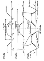
- FIG. 3a shows the baseband spectrum after the pulse shaper as a function of the frequency w
- FIG. 3b the baseband spectrum after the interpolation filter.
- the periodicity intervals are also marked and further names are explained below.
- Fgi. 3c shows the IF spectrum after the multiplier and a basic attenuation curve of an IF postfilter to correct the sine x / x distortion of the D / A converter and to suppress the periodic continuation of the spectrum.
- the modulators 9, 9 'preceding the spectrum-shaping filters are interpolating or decimating bridge wave digital filters which fulfill the Nyquist condition and at the same time perform the sign reversal of every second sample value.
- bridge wave digital filters are described in the simultaneously filed patent application (internal name of the applicant VPA 83 P 1291).
- FIGS. 2a and 2b, or FIG. 3 For a further general explanation of FIGS. 2a and 2b, or FIG. 3, the following should be pointed out in comparison to FIG. 1.
- K 1 and K 2 The choice of the constants K 1 and K 2 according to (2) is of fundamental importance, taking into account (1).
- K 2 4 in particular is an excellent value, since the corresponding scanning sequences for the two carrier oscillations cos w T nT: 1, 0, -1, 0, 1, 0, -1, ... sin w T nT : 0, 1, 0, -1, 0, 1, 0, .
- With has only one non-zero sample value (+ or -1) at each sampling time and thus the merging of the two quadrature channels I, Q becomes particularly simple. This means that the quadrature modulation by simply alternately hiding every second sample and switching through or inverting the remaining values in the quadrature channels and the Merging by interlocking both scan sequences is accomplished.
- the second part of the change in sampling rate thus relates to a sequence whose spectrum has already undergone 50% Nyquist shaping and is intended to bring about the sampling rate of 4 f S required for modulation with as little effort as possible. As shown below, this can be done particularly efficiently with a kind of residual sideband modulation for both quadrature channels.
- an interpolation filter 8, 8 'with the transfer function is used according to FIG. 2a at. Then there is for the baseband spectrum at the multiplier input in the I-channel following a symbol The same applies to the Q channel.
- Equation (4) used in (5) gives the periodicity of F I , Q (w) and it applies
- the basic frequency response is in FIG. 3c of a time-continuous analog IF filter that compensates for the sin x / x distortions of the D / A converter in the pass band and shows the periodic continuation of the spectrum suppressed in the stop band.
- the sin x / x compensation can possibly also be brought forward into the digital part.
Abstract
Spektrumformende digitale Filter werden zur digitalen Quadraturamplitudenmodulation (QAM) verwendet. Bei dem angegebenen Verfahren ist die Frequenz der beiden unter 90° aufeinanderstehenden Trägerschwingungen ein Viertel der Abtastfrequenz und es ist darüber hinaus ihre Phasenlage relativ zu den Abtastzeitpunkten so gewählt, daß abwechselnd jeder zweite Abtastwert beider Trägerschwingungen Null ist.Spectrum-shaping digital filters are used for digital quadrature amplitude modulation (QAM). In the specified method, the frequency of the two carrier oscillations at 90 ° is a quarter of the sampling frequency and, moreover, their phase position relative to the sampling instants is selected so that alternately every second sample of both carrier oscillations is zero.
Description
Die Erfindung betrifft ein Verfahren zur digitalen Quadraturamplitudenmodulation unter Verwendung von spektrumformenden digitalen Filtern, bei der Abtastfolgen aus zwei unter 90° aufeinanderstehenden Trägerschwingungen zur Verfügung stehen.The invention relates to a method for digital quadrature amplitude modulation using spectrum-shaping digital filters, in which scanning sequences from two carrier oscillations at 90 ° to one another are available.
Verfahren zur digitalen Quadraturamplitudenmodulation (QAM) sind dem Grundkonzept nach durch die Literaturstelle NTG Fachberichte (1980), Seiten 81 bis 85 bekanntgeworden. Es werden in dieser Literaturstelle auch digitale, spektrumformende Tiefpässe,- verwendet, anschließend erfolgt die Digital-Analog-Wandlung und die Quadraturamplitudenmodulation erfolgt analog. Entsprechend gilt dies auch für den Empfangsweg.The basic concept of digital quadrature amplitude modulation (QAM) methods has become known through the reference NTG Fachberichte (1980), pages 81 to 85. Digital, spectrum-shaping low-pass filters are also used in this literature reference, followed by digital-analog conversion and quadrature amplitude modulation analog. Accordingly, this also applies to the reception route.
Zu bedenken ist ferner, daß zur Lösung einer Reihe nachrichtentechnischer Probleme Schaltungen erforderlich sind, die die sogenannte Nyquist-Bedingung erfüllen. Diese Bedingung istan.sich definiert, zugehörige Schaltungen werden beispielsweise dann benötigt, wenn es darauf ankommt, Impulse intersymbolstörungsfrei (d.h. ohne Impulsnebensprechen) zu übertragen bzw. Videofrequenzbänder umzusetzen, wobei die Frequenz Null und ein Restseitenband noch übertragen werden muß. Selektionsmittel zur Lösung dieser Aufgabe stehen ebenfalls zur Verfügung. Beispielsweise in der Zeitschrift "Frequenz" 1973, Band 27, Seiten 2 bis 6, werden für die Verarbätung analoger Signale Möglichkeiten zur Synthese von Nyquist-Filtern angegeben. Im Grundkonzept laufen diese Schaltungen darauf hinaus, sogenannte strenge Frequenzweiten zu realisieren, bei denen Filter mit einer sogenannten selbstreziproken charakteristischen Funktion verwendet sind. Inzwischen wird auch die sogenannte digitale Technik bei Nachrichten- übermittlungssystemen eingesetzt, und es steht somit auch das Problem an, hierfür Selektionsmittel zu schaffen, Schaltungen und Netzwerke also, für die sich der Ausdruck "digitale Filter" eingebürgert hat. Beispielsweise sind Möglichkeiten zur Realisierung solcher digitalen Filter recht allgemein in dem Buch von Temes/Mitra "Modern Filter Theory and Design" (Verlag John Wiley & Sons, 1973) angegeben, und dort insbesondere auf den Seiten 505 bis 557. Eine spezielle Gattung dieser Filter sind die sogenannten Wellendigitalfilter. Solche Schaltungen sind beispielsweise in der Deutschen Patentschrift Nr. 20 27 303 bzw. auch in der Zeitschrift "AEÜ",, Band 25 (1971), Seiten 79 bis 89 beschrieben. Wellendigitalfilter haben den Vorteil, daß analoge Referenzfilter unmittelbar digital nachgebildet werden können.It should also be borne in mind that in order to solve a number of communication problems, circuits are required which meet the so-called Nyquist condition. This condition is defined in itself, associated circuits are required, for example, when it is important to transmit pulses without intersymbol interference (ie without pulse cross-talk) or to convert video frequency bands, the frequency zero and a residual sideband still to be transmitted. Selection tools for solving this task are also available. For example, in the magazine "Frequency" 1973, volume 27,
Wie bereits erwähnt, wird in dem eingangs genannten Aufsatz NTG-Faehberichte, Seiten 81 bis 88, die Quadraturamplitodenmodulation analog durchgeführt.As already mentioned, in the above-mentioned article NTG reports, pages 81 to 88, the quadrature amplitode modulation is carried out analogously.
Aufgabe der Erfindung ist es, Möglichkeiten anzugeben, nach denen unter Verwendung von spektrumformenden digitalen Filtern auch alle weiteres. Verfahrensschritte digital durchführbar sind.The object of the invention is to provide options according to which, using spectrum-shaping digital filters, all others. Process steps can be carried out digitally.
Bei Verfahren der einleitend genannten Art wird diese Aufgäbe erfindungsgemäß nach den kennzeichnenden Merkmalen des Patentanspruches 1 gelöst.In processes of the type mentioned in the introduction, this task is solved according to the invention according to the characterizing features of
Weitere vorteilhafte Ausgestaltungen sind in den Unteransprüchen angegeben.Further advantageous refinements are specified in the subclaims.
Anhand von Ausführungsbeispielen wird nachstehend die Erfindung noch näher erläutert.The invention is explained in more detail below on the basis of exemplary embodiments.
Es zeigen in der Zeichnung
- Fig. 1 ein bekanntes Realisierungsschema zum besseren Verständnis,
- Fig. 2a einen erfindungsgemäßen QAM-Modulator mit Pulsformer,
- Fig. 2b einen QAM-Modulator und Demodulator, bei dem Interpolator bzw. Dezimator, Multiplizierer zusammengezogen sind,
- Fig. 3 in Abhängigkeit von der Frequenz ω,
- Fig. 3a das Basisbandspektrum nach dem Pulsformer,
- Fig. 3b das Basisbandspektrum nach dem Interpolationsfilter,
- Fig. 3c das Zwischenfrequenzspektrum (ZF-Spektrum) nach dem Multiplizierer und dem prinzipiellen Dämpfungsverlauf eines ZF-Nachfilters zur Korrektur der sinx/x-Verzerrung des D/A-Wandlers und zur Unterdrückung der periodischen Fortsetzung des Spektrums.
- 1 shows a known implementation scheme for better understanding,
- 2a an inventive QAM modulator with pulse shaper,
- 2b a QAM modulator and demodulator, in which the interpolator or decimator, multiplier are contracted,
- 3 as a function of the frequency ω,
- 3a shows the baseband spectrum after the pulse shaper,
- 3b shows the baseband spectrum after the interpolation filter,
- 3c shows the intermediate frequency spectrum (IF spectrum) after the multiplier and the basic attenuation curve of an IF postfilter to correct the sinx / x distortion of the D / A converter and to suppress the periodic continuation of the spectrum.
In Fig. 1 wird eine Bitfrequenz fB in einen seriellparallel Wandler 1 eingegeben. Es werden die Kanäle I und Q erzeugt, in denen jeweils Stufen 1 bis N angegeben sind. Im I-Kanal und im Q-Kanal schließen sich die Digital-Analog-Wandler 2 bzw. 2' an und es ist anschließend die sogenannte Symbolfrequenz fs zu erkennen, wobei die Beziehung gilt fS = fB/2N, und 2N stufige Signale im I- und Q-Kanal vorhanden sind. Es schließen sich gleichartige Schaltungen zur Nyquist-Pulsformung an, die mit der Bezugsziffer 3 bzw. 3' versehen sind und die die Übertragungsfunktion F = G haben. Es folgen noch die sinx/x Entzerrer 4 und 4', sodaß auch Halteverzerrungen des D/A-Wandlers aufgefangen werden können. Die Nyquist-Pulsformung erfolgt zu 50 % im Modulator und es sind diese Modulatoren im I-Kanal mit 5 und im Q-Kanal mit 5' bezeichnet und es wird die 90° Phasenverschiebung dieser beiden Kanäle durch Multiplikationsfaktoren cos ωT.T bzw. sin ωT.T erreicht. Die Quadraturmodulatoren 5 und 5' sind also Multiplizierer und in einem anschließenden Addierer werden die Kanäle I und Q wieder zusammengefaßt und einem anschließenden Zwischenfrequenzbandpaß 7 zugeführt. Dieser ZF-Bandpaß 7 siebt dann unerwünschte Modulationsprodukte aus. Die D/A-Wandler 2 bzw. 2' müssen bei einer Auflösung von N Bit eine erheblich höhere Genauigkeit, nämlich M = N + (4 .. 6) Bit. Die Wandlungsrate ist dabei gleich der Symbolfrequenz fS.In Fig. 1, a bit frequency fB is input into a serial
Beim herkömmlichen Quadraturmodulator mit Pulsformung nach Fig. 1 wird der serielle Bitstrom zuerst in zwei mehrstufige Symbolströme in einem Seriell-Parallel-Wandler 1 umgesetzt und anschließend D/A-gewandelt(2, 2f. Die Auflösung dieser D/A-Wandler beträgt z.B. bei einem 16 QAM-Verfahren 2 Bit in jedem Quadraturkanal. Die Genauigkeit dieser Wandler muß jedoch erheblich größer als die Auflösung (schätzungsweise um 4..6.Bit, d.h. um den Faktor 16..64) sein. Allgemein gilt folgendes.In the conventional quadrature modulator with pulse shaping according to FIG. 1, the serial bit stream is first converted into two multistage symbol streams in a serial-
Ein 22N-QAM-Verfahren führt auf 2N-stufige Signale in den Quadraturkanälen I, 2 und auf eine N-Bit-Auflösung und eine M = (N+(4...6)) Bit Genauigkeit des D/A-Wandlers. Anschließend erfolgt die'sendeseitige Pulsformung, die gemeinsam mit der identisch auf der Empfangsseite (Demodulator) vorzusehenden Pulsformung die Nyquistbedingung 1. Art erfüllt und somit die Intersymbolstörung verschwindet. Diese identische Aufteilung auf Modulator und Demodulator ist vom Standpunkt der Nachbarkanalbeeinflussung her optimal. In den sendeseitigen Pulsformer wird weiteres eine sin x/x-Entzerrung 4, 4' mit einbezogen, um die Halteverzerrungen der D/A-Vandler auszugleichen.A 2 2N -QAM method leads to 2 N -stage signals in the quadrature channels I, 2 and to an N-bit resolution and an M = (N + (4 ... 6)) bit accuracy of the D / A converter . Subsequently, the 'transmission-end pulse-shaping, which together with the same to be provided on the receiving side (demodulator) pulse shaping satisfies the Nyquist
An die darauffolgende Modulation (Multiplikation 5, 5') ist für die Trägerfrequenz ω folgende Forderung zu stellen:![]()
![]()
Nach der Zusammenführung der beiden Quadraturkanäle I und Q erfolgt die ZF-Selektion (Bandpaß 7) um unerwünschte höhere Modulationsprodukte und Störlinien zu unterdrücken.After merging the two quadrature channels I and Q, IF selection (band pass 7) is carried out in order to suppress undesired higher modulation products and interference lines.
Der Demodulator geht unmittelbar aus dem Modulator durch Umkehrung der Signalflußrichtung hervor. Es entfällt dann der sin x/x-Entzerrer im Pulsformer. Hinzu kommt die Trägerrückgewinnung und die Taktrückgewinnung, die für die kohärente Demodulation und für die Regeneration der Symbole von Wichtigkeit sind. Üblicherweise ist beim konventionellen Realisierungsprinzip keine feste Relation zwischen Träger und Takt gegeben.The demodulator emerges directly from the modulator by reversing the direction of signal flow. The sin x / x equalizer in the pulse shaper is then omitted. Added to this are carrier recovery and clock recovery, which are important for the coherent demodulation and for the regeneration of the symbols. Usually there is no fixed relation between carrier and clock in the conventional realization principle.
Beim Übergang zum digitalen Konzept liegt jedoch auch hier ein wesentlicher Unterschied: Die Abtastfrequenz am Eingang des Modulators (Multiplizierers) muß ein ganzzahliges Vielfaches sowohl der Symbolfrequenz fS als auch der Trägerfrequenz fT sein:
In den Figuren 2a und 2b sind Schaltungsteile enthalten, die bereits anhand der Fig. 1 erläutert wurden. Es sind wiederum zu erkennen die Kanäle Q und I, mit 3a bzw. 3'a ist ein sogenannter interpolierender Pulsformer bezeichnet, dem sich in Fig. 2a ein Interpolator mit der Übertragungsfunktion H (w) anschließt. Diese Interpolatoren sind mit den Bezugsziffern 8 und 8' bezeichnet und sind durch Verzögerungsglieder T, denen Schalter nachgeschaltet sind, dargestellt. Es schließt sich ein Multiplizierer an, der im Q-Kanal mit 9 bezeichnet ist und der die Signalfolge mit der Zahlenfolge 1,0, -1,0,... multipliziert, wenn im Kanal I der Multiplizierer 9' die Signalfolge mit der Zahlenfolge 0, 1, 0, -1, multipliziert.In the figures 2a and 2b circuit parts are included, which are already based on the Fi g . 1 have been explained. The channels Q and I can again be seen, with 3a and 3'a is a so-called interpolating pulse shaper, which is followed in FIG. 2a by an interpolator with the transfer function H (w). These interpolators are designated by the
In Fig. 2a ist durch gestrichelte Linien auch die Symbolfrequenz fS bzw. 2fs bzw. 4fS kenntlich gemacht, d.h. also an Stellen, an denen die Interpolation wirksam wird.In Fig. 2a, the symbol frequency f S or . 2f s or 4f S identified, ie at points where the interpolation takes effect.
In Fig. 2b sind Interpolator und Dezimator zusammengezogen und es ist die Anordnung für die Modulator und Demodulatorseite gezeichnet. Mit der Bezugsziffer 11 bzw. 111 sind wie dies ebenfalls symbolisch dargestellt ist, digitale Schaltungen bezeichnet, die eine Vorzeichenumkehr bewerkstelligen. Zwischen Modulator und Demodulator können,wie dies durch gestrichelte Linien ebenfalls angedeutet ist, die D/A-Wandlungen bzw. die A/D-Wandlungen und weitere Umsetzungen vorgenommen werden.In Fig. 2b, the interpolator and decimator are contracted and the arrangement for the modulator and demodulator side is drawn. The
In Fig. 3a ist, wie eingangs schon erwähnt, das Basisbandspektrum nach dem Pulsformer in Abhängigkeit von der Frequenz w gezeichnet, in Fig. 3b das Basisbandspektrum nach dem Interpolationsfilter. Die Periodizitätsintervalle sind ebenfalls kenntlich gemacht und weitere Bezeichnungen werden nachstehend noch erläutert. In Fgi. 3c ist das ZF-Spektrum nach dem Multiplizierer gezeichnet sowie ein prinzipieller Dämpfungsverlauf eines ZF-Nachfilters zur Korrektur der Sinus x/x-Verzerrung des D/A-Wandlers und zur Unterdrückung der periodischen Fortsetzung des Spektrums.In FIG. 3a, as already mentioned at the beginning, the baseband spectrum after the pulse shaper is drawn as a function of the frequency w, in FIG. 3b the baseband spectrum after the interpolation filter. The periodicity intervals are also marked and further names are explained below. In Fgi. 3c shows the IF spectrum after the multiplier and a basic attenuation curve of an IF postfilter to correct the sine x / x distortion of the D / A converter and to suppress the periodic continuation of the spectrum.
Vorteilhaft ist es, wenn die Modulatoren 9, 9' vorangehenden spektrumformenden Filter die Nyquist-Bedingung erfüllende, interpolierende bzw. dezimierende Brückenwellendigitalfilter sind, die zugleich die Vorzeichenumkehr jedes zweiten Abtastwertes durchführen. Solche Brückenwellendigitalfilter sind in der gleichzeitig eingereichten Patentanmeldung (interne Bezeichnung der Anmelderin VPA 83 P 1291 ) beschrieben.It is advantageous if the
Zur weiteren allgemeinen Erläuterung für die Figuren 2a und 2b, bzw. die Figur 3 sei noch im Vergleich zu Fig. 1 auf folgendes hingewiesen.For a further general explanation of FIGS. 2a and 2b, or FIG. 3, the following should be pointed out in comparison to FIG. 1.
Grundlegende Bedeutung kommt der Wahl der Konstanten K1 und K2 entsprechend (2) unter Beachtung von (1) zu. Darüber hinaus ist es vorteilhaft, wenn die Abtastwerte der sinusförmigen Trägerschwingung nur die Werte +1,0 und -1 annehmen. Dies ist dann der Fall, wenn K2 die werte![]()
![]()
![]()
![]()
Um (1) für alle δE[0, 1] einzuhalten, genügt es![]()
![]()
D.h. für die Modulatoren (Multiplizierer) müssen Abtastfolgen mit fA = 4 FS angeliefert werden. Das bedeutet, daß die pulsformenden Filter interpolieren, d.h. die Abtastrate um den Faktor 4 erhöhen müssen. Diese Interpolation soll zweckmäßig in zwei Stufen um jeweils den Faktor 2 durchgeführt werden. Dabei wird im folgenden jeweils die Spektrums- bzw. Pulsformung vollständig in den ersten Teil der Abtastratenerhöhung (bzw. Absenkung, d.h. Dezimation im Demodulator) verlegt.Ie for the modulators (multipliers) scan sequences with fA = 4 F S must be delivered. This means that the pulse-shaping filters interpolate, ie they have to increase the sampling rate by a factor of 4. This interpolation should be carried out in two stages by a factor of 2 each. In the following, the spectrum or pulse shaping is completely shifted into the first part of the increase in the sampling rate (or decrease, ie decimation in the demodulator).
Der zweite Teil der Abtastratenänderung bezieht sich damit auf eine Folge, deren Spektrum bereits eine 50%ige Nyquistformung erfahren hat und soll mit möglichst geringem Aufwand die zur Modulation erforderliche Abtastrage von 4 fS herbeiführen. Wie im folgenden gezeigt, kann dies mit einer Art Restseitenbandmodulation für beide Quadraturkanäle besonders effizient durchgeführt werden.The second part of the change in sampling rate thus relates to a sequence whose spectrum has already undergone 50% Nyquist shaping and is intended to bring about the sampling rate of 4 f S required for modulation with as little effort as possible. As shown below, this can be done particularly efficiently with a kind of residual sideband modulation for both quadrature channels.
Dazu verwendet man gemäß Fig. 2a ein Interpolationsfilter 8, 8' mit der Übertragungsfunktion


Dieses Ergebnis zeigt, daß das ZF-Spektrum durch einfaches Verschieben des Spektrums am Pulsformerausgang (und evtl. Phasendrehung) entsteht und das Interpolationsfilter keine Verzerrungen verursacht, obwohl es nur einen cos-förmigen Frequenzgang aufweist! Dies ist auf eine Art Restseitenbandmodulation zurückzuführen, wie dies in Fig. 3 anhand der Spektren wiedergegeben ist.This result shows that the IF spectrum is created by simply shifting the spectrum at the pulse shaper output (and possibly phase shift) and the interpolation filter does not cause any distortions, even though it only has a cos-shaped frequency response! This is due to a kind of residual sideband modulation, as shown in FIG. 3 on the basis of the spectra.
Zusätzlich ist in Fig. 3c der prinzipielle Frequenzgang eines zeitkontinuierlichen analogen ZF-Filters, das im Durchlaßbereich die sin x/x-Verzerrungen des D/A-Wandlers ausgleicht und im Sperrbereich die periodische Fortsetzung des Spektrums unterdrückt dargestellt. Die sin x/x-Kompensation kann evtl. auch in den Digitalteil vorgezogen werden.In addition, the basic frequency response is in FIG. 3c of a time-continuous analog IF filter that compensates for the sin x / x distortions of the D / A converter in the pass band and shows the periodic continuation of the spectrum suppressed in the stop band. The sin x / x compensation can possibly also be brought forward into the digital part.
Die hier für den Modulator gezeigte Ableitung gilt in voller Anologie für den Demodulator inklusive Dezimator.The derivation shown here for the modulator applies in full anology to the demodulator including decimator.
Claims (3)
Applications Claiming Priority (2)
| Application Number | Priority Date | Filing Date | Title |
|---|---|---|---|
| DE19833314603 DE3314603A1 (en) | 1983-04-22 | 1983-04-22 | METHOD FOR DIGITAL SQUARE AMPLITUDE MODULATION |
| DE3314603 | 1983-04-22 |
Publications (2)
| Publication Number | Publication Date |
|---|---|
| EP0124031A1 true EP0124031A1 (en) | 1984-11-07 |
| EP0124031B1 EP0124031B1 (en) | 1987-08-26 |
Family
ID=6197068
Family Applications (1)
| Application Number | Title | Priority Date | Filing Date |
|---|---|---|---|
| EP84104427A Expired EP0124031B1 (en) | 1983-04-22 | 1984-04-18 | Digital quadrature amplitude modulation method |
Country Status (4)
| Country | Link |
|---|---|
| US (1) | US4617537A (en) |
| EP (1) | EP0124031B1 (en) |
| JP (1) | JPS59207768A (en) |
| DE (2) | DE3314603A1 (en) |
Cited By (2)
| Publication number | Priority date | Publication date | Assignee | Title |
|---|---|---|---|---|
| EP0308520A1 (en) * | 1987-08-26 | 1989-03-29 | Deutsche ITT Industries GmbH | Digital-Demodulator |
| GB2340352A (en) * | 1998-07-31 | 2000-02-16 | Roke Manor Research | Sampling means for use with rake receivers |
Families Citing this family (9)
| Publication number | Priority date | Publication date | Assignee | Title |
|---|---|---|---|---|
| US4756008A (en) * | 1986-03-03 | 1988-07-05 | Hitachi, Ltd. | Digitized quadrature phase shift keying modulator |
| US4708038A (en) * | 1986-08-29 | 1987-11-24 | Dieter Hellnick | Method for machining and improved modified threaded collar |
| US4777453A (en) * | 1987-05-01 | 1988-10-11 | Silicon Systems Inc. | Quadrature amplitude modulator using switched capacitor filter |
| US5222144A (en) * | 1991-10-28 | 1993-06-22 | Ford Motor Company | Digital quadrature radio receiver with two-step processing |
| US5418818A (en) * | 1992-09-22 | 1995-05-23 | Glenayre Electronics, Inc. | Digital signal processor exciter |
| JPH07321862A (en) * | 1994-05-25 | 1995-12-08 | Matsushita Electric Ind Co Ltd | Digitally modulated wave demodulator |
| US5764701A (en) * | 1996-03-04 | 1998-06-09 | Zenith Electronics Corporation | VSB modulator |
| US6724439B1 (en) | 2000-08-04 | 2004-04-20 | Zenith Electronics Corporation | Low cost VSB encoder and RF modulator for supplying a substantially 6 MHZ VSB signal to digital television receiver |
| GB2382282B (en) * | 2001-11-19 | 2003-11-12 | Lucent Technologies Inc | A digital demodulator a telecommunications receiver and a method of digital demodulation |
Citations (1)
| Publication number | Priority date | Publication date | Assignee | Title |
|---|---|---|---|---|
| US4003002A (en) * | 1974-09-12 | 1977-01-11 | U.S. Philips Corporation | Modulation and filtering device |
Family Cites Families (6)
| Publication number | Priority date | Publication date | Assignee | Title |
|---|---|---|---|---|
| US3573380A (en) * | 1969-05-15 | 1971-04-06 | Bell Telephone Labor Inc | Single-sideband modulation system |
| US3887768A (en) * | 1971-09-14 | 1975-06-03 | Codex Corp | Signal structures for double side band-quadrature carrier modulation |
| US4086536A (en) * | 1975-06-24 | 1978-04-25 | Honeywell Inc. | Single sideband transmitter apparatus |
| JPS5627551A (en) * | 1979-08-10 | 1981-03-17 | Nippon Telegr & Teleph Corp <Ntt> | Digital arithmetic modulator and demodulator |
| FR2472876A1 (en) * | 1979-12-31 | 1981-07-03 | Bic Jean Claude | MODULATOR-DEMODULATOR FOR DUAL MODULATION TRANSMISSION OF FOUR-LEVEL AMPLITUDE ON QUADRATURE CARRIERS |
| US4358853A (en) * | 1981-01-22 | 1982-11-09 | Codex Corporation | Digital modem transmitter |
-
1983
- 1983-04-22 DE DE19833314603 patent/DE3314603A1/en not_active Withdrawn
-
1984
- 1984-03-30 US US06/595,527 patent/US4617537A/en not_active Expired - Lifetime
- 1984-04-18 DE DE8484104427T patent/DE3465679D1/en not_active Expired
- 1984-04-18 EP EP84104427A patent/EP0124031B1/en not_active Expired
- 1984-04-23 JP JP59080380A patent/JPS59207768A/en active Granted
Patent Citations (1)
| Publication number | Priority date | Publication date | Assignee | Title |
|---|---|---|---|---|
| US4003002A (en) * | 1974-09-12 | 1977-01-11 | U.S. Philips Corporation | Modulation and filtering device |
Non-Patent Citations (1)
| Title |
|---|
| 1978 NATIONAL TELECOMMUNICATIONS CONFERENCE RECORD, Band 3, Dezember 1978, Seiten 46.6.1 - 46.6.4, New York, USA; A. TANNHÄUSER et al.: "Aspects of digital signal processing in voice band modems" * |
Cited By (4)
| Publication number | Priority date | Publication date | Assignee | Title |
|---|---|---|---|---|
| EP0308520A1 (en) * | 1987-08-26 | 1989-03-29 | Deutsche ITT Industries GmbH | Digital-Demodulator |
| US4827515A (en) * | 1987-08-26 | 1989-05-02 | Deutsche Itt Industries Gmbh | Digital demodulator |
| GB2340352A (en) * | 1998-07-31 | 2000-02-16 | Roke Manor Research | Sampling means for use with rake receivers |
| GB2340352B (en) * | 1998-07-31 | 2003-05-07 | Roke Manor Research | Sampling means for use with rake receiver |
Also Published As
| Publication number | Publication date |
|---|---|
| DE3465679D1 (en) | 1987-10-01 |
| DE3314603A1 (en) | 1984-10-25 |
| JPH0137057B2 (en) | 1989-08-03 |
| EP0124031B1 (en) | 1987-08-26 |
| JPS59207768A (en) | 1984-11-24 |
| US4617537A (en) | 1986-10-14 |
Similar Documents
| Publication | Publication Date | Title |
|---|---|---|
| EP0208982B1 (en) | Digital branch filter for a data receiver | |
| DE2721850C2 (en) | Filter and demodulation arrangement | |
| DE19651720A1 (en) | Digital modulator e.g. for CATV | |
| DE4343510C2 (en) | Method and device for generating the baseband signal of a multi-stage superimposed amplitude-modulated signal | |
| DE2540473A1 (en) | MODULATION AND FILTER DEVICE | |
| CH647368A5 (en) | PLANT FOR TRANSMITTING BINARY DATA SIGNALS. | |
| DE69917514T2 (en) | Filtering for transmission using quadrature modulation | |
| DE3202005A1 (en) | DATA MODULATOR TRANSMITTER | |
| DE2540836B2 (en) | DEMODULATOR FOR 16-VALUE ASPK SIGNALS | |
| EP0124031B1 (en) | Digital quadrature amplitude modulation method | |
| DE2831059C2 (en) | Integrating code converter | |
| DE2401814C3 (en) | Equalization of a phase-modulated signal | |
| DE60032075T2 (en) | Digital vestigial sideband modulator | |
| DE60303998T2 (en) | Converter circuit, tuner circuit and demodulator | |
| DE10234823B4 (en) | Method for dividing the bit rate of QPSK signals into two or more subchannels | |
| DE3015217C2 (en) | Transmission method and corresponding transmitter and receiver for the transmission of two-valued data symbols | |
| DE69634621T2 (en) | Arrangement for data reproduction with time sampling | |
| DE2416058A1 (en) | METHOD AND CIRCUIT ARRANGEMENTS FOR EQUALIZATION OF A CARRIER-MODULATING DATA SIGNAL | |
| DE19946722A1 (en) | Device and method for spectrally shaping a transmission signal in a radio transmitter | |
| DE3839919C2 (en) | ||
| WO2001060007A1 (en) | Method and circuit arrangement for demodulation of a quadrature amplitude- or phase-modulated signal | |
| EP0760567A2 (en) | Digital QAM modulator | |
| DE2833889C2 (en) | Digital transmission filter in data transmission equipment | |
| EP1203457B1 (en) | Reception method and receiver array for a duplex transmission system | |
| EP0706274B1 (en) | Method for clock synchronisation in a receiver of a transmission system |
Legal Events
| Date | Code | Title | Description |
|---|---|---|---|
| PUAI | Public reference made under article 153(3) epc to a published international application that has entered the european phase |
Free format text: ORIGINAL CODE: 0009012 |
|
| AK | Designated contracting states |
Designated state(s): DE FR IT |
|
| 17P | Request for examination filed |
Effective date: 19841221 |
|
| GRAA | (expected) grant |
Free format text: ORIGINAL CODE: 0009210 |
|
| AK | Designated contracting states |
Kind code of ref document: B1 Designated state(s): DE FR IT |
|
| REF | Corresponds to: |
Ref document number: 3465679 Country of ref document: DE Date of ref document: 19871001 |
|
| ET | Fr: translation filed | ||
| ITF | It: translation for a ep patent filed |
Owner name: STUDIO JAUMANN |
|
| PLBE | No opposition filed within time limit |
Free format text: ORIGINAL CODE: 0009261 |
|
| STAA | Information on the status of an ep patent application or granted ep patent |
Free format text: STATUS: NO OPPOSITION FILED WITHIN TIME LIMIT |
|
| 26N | No opposition filed | ||
| ITTA | It: last paid annual fee | ||
| PGFP | Annual fee paid to national office [announced via postgrant information from national office to epo] |
Ref country code: FR Payment date: 20010420 Year of fee payment: 18 |
|
| PG25 | Lapsed in a contracting state [announced via postgrant information from national office to epo] |
Ref country code: FR Free format text: LAPSE BECAUSE OF NON-PAYMENT OF DUE FEES Effective date: 20021231 |
|
| REG | Reference to a national code |
Ref country code: FR Ref legal event code: ST |
|
| PGFP | Annual fee paid to national office [announced via postgrant information from national office to epo] |
Ref country code: DE Payment date: 20030616 Year of fee payment: 20 |