EP0126520A2 - Prosthetic ligament and instruments for use in the surgical replacement of ligaments - Google Patents
Prosthetic ligament and instruments for use in the surgical replacement of ligaments Download PDFInfo
- Publication number
- EP0126520A2 EP0126520A2 EP84300875A EP84300875A EP0126520A2 EP 0126520 A2 EP0126520 A2 EP 0126520A2 EP 84300875 A EP84300875 A EP 84300875A EP 84300875 A EP84300875 A EP 84300875A EP 0126520 A2 EP0126520 A2 EP 0126520A2
- Authority
- EP
- European Patent Office
- Prior art keywords
- ligament
- bone
- further characterised
- prosthetic
- perforations
- Prior art date
- Legal status (The legal status is an assumption and is not a legal conclusion. Google has not performed a legal analysis and makes no representation as to the accuracy of the status listed.)
- Granted
Links
Images


Classifications
-
- A—HUMAN NECESSITIES
- A61—MEDICAL OR VETERINARY SCIENCE; HYGIENE
- A61F—FILTERS IMPLANTABLE INTO BLOOD VESSELS; PROSTHESES; DEVICES PROVIDING PATENCY TO, OR PREVENTING COLLAPSING OF, TUBULAR STRUCTURES OF THE BODY, e.g. STENTS; ORTHOPAEDIC, NURSING OR CONTRACEPTIVE DEVICES; FOMENTATION; TREATMENT OR PROTECTION OF EYES OR EARS; BANDAGES, DRESSINGS OR ABSORBENT PADS; FIRST-AID KITS
- A61F2/00—Filters implantable into blood vessels; Prostheses, i.e. artificial substitutes or replacements for parts of the body; Appliances for connecting them with the body; Devices providing patency to, or preventing collapsing of, tubular structures of the body, e.g. stents
- A61F2/02—Prostheses implantable into the body
- A61F2/08—Muscles; Tendons; Ligaments
- A61F2/0805—Implements for inserting tendons or ligaments
-
- A—HUMAN NECESSITIES
- A61—MEDICAL OR VETERINARY SCIENCE; HYGIENE
- A61B—DIAGNOSIS; SURGERY; IDENTIFICATION
- A61B17/00—Surgical instruments, devices or methods, e.g. tourniquets
- A61B17/16—Bone cutting, breaking or removal means other than saws, e.g. Osteoclasts; Drills or chisels for bones; Trepans
- A61B17/17—Guides or aligning means for drills, mills, pins or wires
- A61B17/1714—Guides or aligning means for drills, mills, pins or wires for applying tendons or ligaments
-
- A—HUMAN NECESSITIES
- A61—MEDICAL OR VETERINARY SCIENCE; HYGIENE
- A61B—DIAGNOSIS; SURGERY; IDENTIFICATION
- A61B17/00—Surgical instruments, devices or methods, e.g. tourniquets
- A61B17/16—Bone cutting, breaking or removal means other than saws, e.g. Osteoclasts; Drills or chisels for bones; Trepans
- A61B17/17—Guides or aligning means for drills, mills, pins or wires
- A61B17/1739—Guides or aligning means for drills, mills, pins or wires specially adapted for particular parts of the body
- A61B17/1764—Guides or aligning means for drills, mills, pins or wires specially adapted for particular parts of the body for the knee
Definitions
- This invention relates to a new prosthetic ligament . and a set of surgical instruments for use in the surgical replacement of a ligament and in particular for inserting a prosthetic ligament into the body.
- One ligament which has been proposed in U S Patent number 4255820 comprises a foraminous tube which has perforations of different size and density along its length.
- the perforations in the central portion of the ligament which extends between the two bones are very small in order to prevent any tissue ingrowth in this area.
- An internal central core is inserted into this area to help ensure that no tissue ingrowth occurs.
- a prosthetic ligament for implantation between two bores, the ligameat being elongate and flexible and including two ends, each end for fixation to a bone, with a central portion of ligament extending between said ends, said central portion comprising a foraminous polyester strip characterised in that the central portion includes perforations having an area of at least 0.01 cm 2 so that tissue ingrowth into the central portion is promoted.
- the size and distribution of the perforations in the ligament is substantially uniform along the entire length of the ligament.
- the ligament may.be a perforated strip of material but is preferably a fabric with an open weave structure.
- the polyester is polyethylene terephthalate or a copolymer thereof, for instance, the material which is marketed under the trade mark "Terylene” in the U K and under the trade mark “Dacron” in U S A.
- the weave of the fabric may be knitted open net but is preferably mock leno or leno woven, in which the weft threads are locked with respect to the warp threads.
- Each perforation is preferably in the range of 0.01 to 0.05 cm 2 and is more preferably in the range of 0.01 to 0.02 cm 2 .
- such a ligament is fixed within the body by threading the prosthetic ligament through a bore in the two bones to be joined by the ligament.
- Each bore comprises a reduced diameter portion which extends from the point at which the original ligament was attached to the bone and an enlarged diameter portion formed by removing a plug of bone.
- the bone plugs are replaced into these enlarged diametersportions when the ligament has been inserted thus securing the ligament between the bone plug and the rest of the bone.
- the perforations in the ligament which extend through the length of the ligament promote growth of the tissue.
- the perforations in the region of the bone encourage bone growth which grows between the bone plug and the rest of the bone thus securing and giving a good fixation to the prosthetic ligament.
- the perforations in the region between the two bones encourages tissue growth along the length of the ligament which can strengthen the ligament considerably.
- the ligament may be formed from a length cut from an elongate strip which is inserted in the body and then trimmed once the ligament is fixed in place. Clearly the perforations need only exist in the part of the ligament which remains in the body..
- a particularly useful structure for the prosthetic ligament is for the ligament to be formed from a tube of open weave polyester.
- the tube includes a longitudinal slit at each end of the ligament.
- One of the slits extends to one end edge of the ligament.
- At the other end of the ligament at the end of that slit which is remote from the centre of the ligament is a closure which seals off the tube.
- the ligament also includes means to pull the ligament through the two.bores in the bones.
- this is in the form of a cord attached to one end of the ligament which may easily be threaded through the small bores.
- the ligament is trimmed after the bone plugs have been inserted, the trimming removing the cord for threading the ligament through the bones and the sealed end of the slit.
- a clamp for locating the axis along the bore through which the ligament is to be threaded comprises two parallel limbs which are connected by two screw threaded members which extend perpendicularly of the limbs, one limb including a guide pin which extends perpendicular to the limb, the other limb including two guide pins parallel to this first guide pin and aligned with the guide pin and a cylindrical guide, to which they are attached, for receiving surgical instruments, the axis of the cylinder lying on the line of the first guide pin, the cylindrical guide being such that the edge of the cylinder lying between two limbs is tilted such that when the first guide pin is placed at the point where the original ligament was attached to the bone and the clamp is rotated until the angle of the tilt of the cylinder guide is parallel to the angle of the bone and the clamp is tightened, the axis extending from the centre of the cylindrical guide to the first guide pin is the required axis for the bore.
- the handles used to tighten the screw threaded members are adjacent each other on the same side of the parallel limbs so that a surgeon only requires access to one side of the clamp.
- a reamer is inserted in the cylindrical guide and is used to remove an annulus of bone dust from the bone. This locates the plug of bone to be removed and the clamp can now be removed. Very occasionally the bone plug may be retained within the reamer.
- the reamer includes an opening through which a rod may be inserted to urge the plug out of the reamer.
- a bone plug extractor comprises a hollow cylindrical member of the same diameter as the annulus of bone dust removed from the bone and of a depth greater than that removed by the reamer, the cylinder including a cut out portion at the end inserted into the annulus in the bone, and including a flattened portion which does not enter the bone, the flattened portion forming a bearing surface to which is applied a short strong force to knock the annulus of bone to remove the bone plug from the rest of the bone.
- the bone plug extractor preferably includes a handle which may be gripped whilst the force is applied sotthat no bone damage occurs.
- the bone plug may be removed from the plug extractor .by inserting a rod into the cut out portion.
- a cylindrical guide is placed into the cylinder in the bone, a drill bit is then placed within the cylindrical guide and a reduced diameter portion is then drilled from the base of the cylinder to the other side of the bone at the point where the original ligament was attached to the bone.
- a set of tools according to this invention includes an above mentioned clamp, a reamer which cooperates with this clamp, a bone plug extractor of the same diameter as the annulus of the reamer, a rod which may be used with the bone plug extractor, and a:cylindrical drill bit guide of the same diameter as the reamer and bone plug extractor.
- this ligament is used to replace the cruciate ligaments of the knee. It can also, in another form, for instance a flat strip, be used to replace the medial ligament of the knee.
- An artificial ligament 1 comprises an elongate strip of open weave polyester.
- This fabric is Terylene and is a mock leno weave comprising a warp of 550 Decitex polyester yarn and a weft of twisted polyester yarn.
- the holes are 0.1 x 0.5 cm. There are 14 to 15 holes across the width of the strip, and 20 holes per cm 2 .
- the ligament is in the form of a tube 2 which has a slit 3 at one open end of the ligament 1 which extends to the open end edge of the ligament and a slit 4 at the other closed end of the ligament.
- the end of the slit 4 remote from the centre of the tube 2 is sealed by a row or more of stitching 5 or a comparable method, to form a pouch.
- the ligament 1 has been shown in Figure 1 with a dark coloured tubular insert. This means that the pouch-like structure is not clearly illustrated.
- a cord 6 is attached to the end of the ligament to pull the ligament through the bores in the bone.
- a set of surgical instruments for use in the implantation of the ligament comprises a clamp 7, a reamer 8, a bone plug extractor 9, and a drill bit guide 12,
- the clamp 7 comprises two parallel limbs 13, 14 connected by two perpendicular screw threaded members 15 and 16.
- One limb includes a first guide pin 17 standing perpendicularly of the limb.
- the other limb 14 includes two guide pins 18 which are parallel to the guide pin 17 and extend towards the guide pin 17.
- Also connected to limb 14 is a cylindrical guide 19 which has a surface 20 between the two limbs which is tilted, the two guide pins are screwed into the cylindrical guide 19.
- the reamer 8 passes through the cylindrical guide 19 and has sharp cutting edges 21, which are milled along its surface and form sharp teeth at the rim of the reamer, and a handle 22 which may be used to oscillate the cutting edges 21 to remove the bone dust.
- the bone plug extractor 9 comprises a cylindrical portion 23 which includes a cut-out portion 24.
- the bone plug extractor 9 has a flattened portion 25 on its handle.
- the diameter of the cylindrical portion 23 is the:same as the reamer.
- the drill bit guide 12 is placed in the cylindrical hole created in the bone and is used as a guide for the drill bit to drill out the reduced diameter portion of the bore.
- the anterior cruciate ligament in the knee is connected to the femur 26 and the tibia 27.
- the clamp 7 is placed around the femur 26 with the first guide pin 17 placed at the point of attachment 28 where the original ligament was attached to the femur 26.
- the clamp is then rotated until the sloping edge 20 of the cylindrical guide 19 is aligned to the slope of the bone 26.
- the clamp 7 is then tightened up locating the axis of the bore.
- the reamer 8 is then placed within the cylindrical guide 20 and the handle 22 is oscillated to remove an annulus of bone dust (Figure 6).
- the reamer is then removed from the bone.
- a rod is inserted into the reamer to remove the bone plug.
- the bone plug extractor 9 is then placed in the annulus defined in the femur 26.
- a swift force is applied to the flattened surface 25 to remove the bone plug from the bone, whilst the bone plug extractor 9 is gripped firmly.
- the bone plug may be-removed from the bone plug extractor 9 by inserting a rod into opening 24.
- the drill bit guide 12 is then placed in the cylindrical hole left in the femur 26 and a drill bit is then placed within the guide 12 to drill out the reduced diameter portion 28 of the bore 29 now formed through the femur 26.
- the bone plug from the femur 26 is then forced into the opening 3, aided by a push rod.
- the ligament la is secured to both the femur and tibia.
- the anchorage will be strengthened as a result of the bone growth between the bone plug and the rest of the bone. Also tissue growth is encouraged along the length of ligament between the bones thus strengthening the ligament.
Abstract
Description
- This invention relates to a new prosthetic ligament . and a set of surgical instruments for use in the surgical replacement of a ligament and in particular for inserting a prosthetic ligament into the body.
- In the past damaged ligaments have been replaced by grafts from other tissues of the body. However, this is not satisfactory since extensive surgery is involved and the fixation of the replacement ligament is not always adequate. Also, solid tubes of polyethylene have been used as ligaments but again the fixation of these ligaments was not satisfactory, and, further, the structure of the ligament was not suitable. Around three of four years ago carbon fibres were introduced as a possible ligament prosthesis. Holes are drilled into the bones to be joined by the ligament and multifilament strands of carbon fibres are thread through these holes, the carbon fibres being long enough to allow the strands to be knotted to fix the fibres into position. The carbon fibre proves stronger than previous materials and growth of tissue is encouraged along the length of the fibres. However, the holes which are required to be drilled in each bone are numerous and this involves large destruction ofbone material which is not desirable. Further, control of the length of the ligament and its tension has proved very difficult, and anchoring to the bone has not been accepted to any degree of consistency.
- One ligament which has been proposed in U S Patent number 4255820, comprises a foraminous tube which has perforations of different size and density along its length. The perforations in the central portion of the ligament which extends between the two bones are very small in order to prevent any tissue ingrowth in this area. An internal central core is inserted into this area to help ensure that no tissue ingrowth occurs.
- According to this invention there is provided a prosthetic ligament for implantation between two bores, the ligameat being elongate and flexible and including two ends, each end for fixation to a bone, with a central portion of ligament extending between said ends, said central portion comprising a foraminous polyester strip characterised in that the central portion includes perforations having an area of at least 0.01 cm2 so that tissue ingrowth into the central portion is promoted.
- In order to simplify the manufacturing process of the ligament it is preferred that the size and distribution of the perforations in the ligament is substantially uniform along the entire length of the ligament.
- The ligament may.be a perforated strip of material but is preferably a fabric with an open weave structure. Preferably the polyester is polyethylene terephthalate or a copolymer thereof, for instance, the material which is marketed under the trade mark "Terylene" in the U K and under the trade mark "Dacron" in U S A. The weave of the fabric may be knitted open net but is preferably mock leno or leno woven, in which the weft threads are locked with respect to the warp threads.
- Preferably there are 10-40 perforations per square cm and more preferably 15-25 perforations per cm .
- Each perforation is preferably in the range of 0.01 to 0.05 cm2 and is more preferably in the range of 0.01 to 0.02 cm 2 .
- Preferably such a ligament is fixed within the body by threading the prosthetic ligament through a bore in the two bones to be joined by the ligament. Each bore comprises a reduced diameter portion which extends from the point at which the original ligament was attached to the bone and an enlarged diameter portion formed by removing a plug of bone. The bone plugs are replaced into these enlarged diametersportions when the ligament has been inserted thus securing the ligament between the bone plug and the rest of the bone. The perforations in the ligament which extend through the length of the ligament promote growth of the tissue. The perforations in the region of the bone encourage bone growth which grows between the bone plug and the rest of the bone thus securing and giving a good fixation to the prosthetic ligament. The perforations in the region between the two bones encourages tissue growth along the length of the ligament which can strengthen the ligament considerably.
- The ligament may be formed from a length cut from an elongate strip which is inserted in the body and then trimmed once the ligament is fixed in place. Clearly the perforations need only exist in the part of the ligament which remains in the body..
- - A particularly useful structure for the prosthetic ligament is for the ligament to be formed from a tube of open weave polyester. The tube includes a longitudinal slit at each end of the ligament. One of the slits extends to one end edge of the ligament. At the other end of the ligament, at the end of that slit which is remote from the centre of the ligament is a closure which seals off the tube.
- When the ligament is inserted in the bone, a bone plug is inserted in the slit adjacent the seal and the other end of the ligament is pulled. This means that the bone plug is forced between the shoulder between the enlarged portion and the reduced diameter portion of the bore and the seal giving a good fixed location of the ligament. The-other bone plug is then inserted through the slit at the other end of the ligament and forced against the shoulder in the other bone thus securing the ligament to both bones.
- Preferably the ligament also includes means to pull the ligament through the two.bores in the bones. Preferably this is in the form of a cord attached to one end of the ligament which may easily be threaded through the small bores.
- Preferably the ligament is trimmed after the bone plugs have been inserted, the trimming removing the cord for threading the ligament through the bones and the sealed end of the slit.
- Also in accordance with this invention there is provided a set of surgical instruments for use in the surgical replacement of an artificial ligament.
- According to this invention a clamp for locating the axis along the bore through which the ligament is to be threaded comprises two parallel limbs which are connected by two screw threaded members which extend perpendicularly of the limbs, one limb including a guide pin which extends perpendicular to the limb, the other limb including two guide pins parallel to this first guide pin and aligned with the guide pin and a cylindrical guide, to which they are attached, for receiving surgical instruments, the axis of the cylinder lying on the line of the first guide pin, the cylindrical guide being such that the edge of the cylinder lying between two limbs is tilted such that when the first guide pin is placed at the point where the original ligament was attached to the bone and the clamp is rotated until the angle of the tilt of the cylinder guide is parallel to the angle of the bone and the clamp is tightened, the axis extending from the centre of the cylindrical guide to the first guide pin is the required axis for the bore.
- Preferably the handles used to tighten the screw threaded members are adjacent each other on the same side of the parallel limbs so that a surgeon only requires access to one side of the clamp.
- When the clamp has been placed on the bone, a reamer is inserted in the cylindrical guide and is used to remove an annulus of bone dust from the bone. This locates the plug of bone to be removed and the clamp can now be removed. Very occasionally the bone plug may be retained within the reamer. Preferably the reamer includes an opening through which a rod may be inserted to urge the plug out of the reamer.
- According to this invention a bone plug extractor comprises a hollow cylindrical member of the same diameter as the annulus of bone dust removed from the bone and of a depth greater than that removed by the reamer, the cylinder including a cut out portion at the end inserted into the annulus in the bone, and including a flattened portion which does not enter the bone, the flattened portion forming a bearing surface to which is applied a short strong force to knock the annulus of bone to remove the bone plug from the rest of the bone.
- The bone plug extractor preferably includes a handle which may be gripped whilst the force is applied sotthat no bone damage occurs.
- The bone plug may be removed from the plug extractor .by inserting a rod into the cut out portion.
- When the bone plug has been removed a cylindrical guide is placed into the cylinder in the bone, a drill bit is then placed within the cylindrical guide and a reduced diameter portion is then drilled from the base of the cylinder to the other side of the bone at the point where the original ligament was attached to the bone.
- This process is then repeated with the other bone to which the ligament is to be attached, the same instruments being used again.
- Thus a set of tools according to this invention includes an above mentioned clamp, a reamer which cooperates with this clamp, a bone plug extractor of the same diameter as the annulus of the reamer, a rod which may be used with the bone plug extractor, and a:cylindrical drill bit guide of the same diameter as the reamer and bone plug extractor.
- Preferably this ligament is used to replace the cruciate ligaments of the knee. It can also, in another form, for instance a flat strip, be used to replace the medial ligament of the knee.
- A prosthetic ligament and a set of surgical instruments and a method of inserting the ligament into the body will now be described by way of example only, with reference to the accompanying drawings, in which;-
- Figure 1 is a perspective view of the prosthetic ligament;
- Figure 2 is a perspective view of the clamp, reamer, drill bit guide;
- Figure 3 is a perspective view of the bone plug extractor;
- Figures 4 to 10 are schematic representations of the steps of the method of replacing an anterior cruciate ligament in the knee.
- An artificial ligament 1 comprises an elongate strip of open weave polyester. This fabric is Terylene and is a mock leno weave comprising a warp of 550 Decitex polyester yarn and a weft of twisted polyester yarn. The holes are 0.1 x 0.5 cm. There are 14 to 15 holes across the width of the strip, and 20 holes per cm2.
- The ligament is in the form of a
tube 2 which has a slit 3 at one open end of the ligament 1 which extends to the open end edge of the ligament and aslit 4 at the other closed end of the ligament. The end of theslit 4 remote from the centre of thetube 2 is sealed by a row or more of stitching 5 or a comparable method, to form a pouch. In order to illustrate theslit 4, the ligament 1 has been shown in Figure 1 with a dark coloured tubular insert. This means that the pouch-like structure is not clearly illustrated. Acord 6 is attached to the end of the ligament to pull the ligament through the bores in the bone. - A set of surgical instruments for use in the implantation of the ligament comprises a clamp 7, a
reamer 8, a bone plug extractor 9, and a drill bit guide 12, - The clamp 7 comprises two
parallel limbs 13, 14 connected by two perpendicular screw threadedmembers first guide pin 17 standing perpendicularly of the limb. The other limb 14 includes two guide pins 18 which are parallel to theguide pin 17 and extend towards theguide pin 17. Also connected to limb 14 is acylindrical guide 19 which has asurface 20 between the two limbs which is tilted, the two guide pins are screwed into thecylindrical guide 19. - The
reamer 8 passes through thecylindrical guide 19 and hassharp cutting edges 21, which are milled along its surface and form sharp teeth at the rim of the reamer, and ahandle 22 which may be used to oscillate the cutting edges 21 to remove the bone dust. - The bone plug extractor 9 comprises a
cylindrical portion 23 which includes a cut-outportion 24. - The bone plug extractor 9 has a flattened
portion 25 on its handle. The diameter of thecylindrical portion 23 is the:same as the reamer. - The drill bit guide 12 is placed in the cylindrical hole created in the bone and is used as a guide for the drill bit to drill out the reduced diameter portion of the bore.
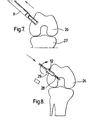
- The anterior cruciate ligament in the knee is connected to the
femur 26 and thetibia 27. As shown in Figure 4, the clamp 7 is placed around thefemur 26 with thefirst guide pin 17 placed at the point ofattachment 28 where the original ligament was attached to thefemur 26. The clamp is then rotated until the slopingedge 20 of thecylindrical guide 19 is aligned to the slope of thebone 26. The clamp 7 is then tightened up locating the axis of the bore. - As shown in Figure 5 the
reamer 8 is then placed within thecylindrical guide 20 and thehandle 22 is oscillated to remove an annulus of bone dust (Figure 6). The reamer is then removed from the bone. In the infrequent possibility that the bone plug is removed with the reamer, a rod is inserted into the reamer to remove the bone plug. - As shown in Figure 7 the bone plug extractor 9 is then placed in the annulus defined in the
femur 26. A swift force is applied to the flattenedsurface 25 to remove the bone plug from the bone, whilst the bone plug extractor 9 is gripped firmly. The bone plug may be-removed from the bone plug extractor 9 by inserting a rod intoopening 24. - The drill bit guide 12 is then placed in the cylindrical hole left in the
femur 26 and a drill bit is then placed within theguide 12 to drill out the reduceddiameter portion 28 of thebore 29 now formed through thefemur 26. - This procedure is then repeated in the tibia forming a bore in the tibia. The ligament 1 is then threaded through the two
bores 29 using thecord 6. The bone plug from thetibia 27 is then placed within theslit 4 in the ligament. - The other end of the ligament 1 is then pulled forcing the bone plug against the shoulder formed between the enlarged portion and the reduced
diameter portion 28 by the sealedend 5. - The bone plug from the
femur 26 is then forced into the opening 3, aided by a push rod. Thus the ligament la is secured to both the femur and tibia. - Subsequently the anchorage will be strengthened as a result of the bone growth between the bone plug and the rest of the bone. Also tissue growth is encouraged along the length of ligament between the bones thus strengthening the ligament.
Claims (18)
Priority Applications (5)
| Application Number | Priority Date | Filing Date | Title |
|---|---|---|---|
| AT84300875T ATE43062T1 (en) | 1983-02-16 | 1984-02-13 | ARTIFICIAL LIGAMENT AND INSTRUMENTS FOR SURGICAL REPLACEMENT OF THESE LIGAMENTS. |
| AT85300931T ATE63049T1 (en) | 1984-02-13 | 1985-02-13 | INSTRUMENTS FOR SURGICAL REPLACEMENT OF LIGAMENTS. |
| EP19850300931 EP0153831B1 (en) | 1984-02-13 | 1985-02-13 | Instruments for use in the surgical replacement of ligaments |
| JP2614985A JPS60241434A (en) | 1984-02-13 | 1985-02-13 | Bone plug extractor, artificial tendon replacing instrument and attachment and detachment of said tendon |
| DE8585300931T DE3582689D1 (en) | 1984-02-13 | 1985-02-13 | INSTRUMENTS FOR SURGICAL REPLACEMENT OF LIGAMENTS. |
Applications Claiming Priority (2)
| Application Number | Priority Date | Filing Date | Title |
|---|---|---|---|
| GB8304264 | 1983-02-16 | ||
| GB838304264A GB8304264D0 (en) | 1983-02-16 | 1983-02-16 | Prosthetic ligament |
Publications (3)
| Publication Number | Publication Date |
|---|---|
| EP0126520A2 true EP0126520A2 (en) | 1984-11-28 |
| EP0126520A3 EP0126520A3 (en) | 1986-01-15 |
| EP0126520B1 EP0126520B1 (en) | 1989-05-17 |
Family
ID=10538068
Family Applications (1)
| Application Number | Title | Priority Date | Filing Date |
|---|---|---|---|
| EP84300875A Expired EP0126520B1 (en) | 1983-02-16 | 1984-02-13 | Prosthetic ligament and instruments for use in the surgical replacement of ligaments |
Country Status (6)
| Country | Link |
|---|---|
| US (1) | US4668233A (en) |
| EP (1) | EP0126520B1 (en) |
| JP (1) | JPS59207145A (en) |
| AT (1) | ATE43062T1 (en) |
| DE (1) | DE3478193D1 (en) |
| GB (1) | GB8304264D0 (en) |
Cited By (22)
| Publication number | Priority date | Publication date | Assignee | Title |
|---|---|---|---|---|
| EP0153831A2 (en) * | 1984-02-13 | 1985-09-04 | Bahaa Botros Seedhom | Instruments for use in the surgical replacement of ligaments |
| EP0201667A1 (en) * | 1985-05-03 | 1986-11-20 | GebràDer Sulzer Aktiengesellschaft | Artificial tendon made of a tubular textile structure |
| FR2586927A1 (en) * | 1985-09-06 | 1987-03-13 | Bristol Myers Co | ASSEMBLY ASSEMBLY OF A PROSTHESIS LIGAMENT |
| US4665951A (en) * | 1985-03-11 | 1987-05-19 | Ellis Julian G | Prosthetic ligament |
| EP0223370A2 (en) * | 1985-10-17 | 1987-05-27 | Bahaa Botros Seedhom | Prosthetic ligament |
| FR2590792A1 (en) * | 1985-12-04 | 1987-06-05 | Breard Francis | Ligament staple, in particular for implanting artificial joint ligaments |
| US4823780A (en) * | 1984-03-14 | 1989-04-25 | Odensten Magnus G | Drill guiding and aligning device |
| FR2626763A1 (en) * | 1986-10-03 | 1989-08-11 | Temple University Commonwealth | DEVICE AND METHOD FOR IDENTIFYING OPTIMAL LOCATIONS OF TUNNELS TO BE PRACTICAL IN BONES FOR THE REPLACEMENT OF LIGAMENTS OF AN ARTICULATION |
| WO1989010101A1 (en) * | 1988-04-29 | 1989-11-02 | Bahaa Botros Seedhom | Mechanical fixation of prosthetic ligament |
| EP0358324A1 (en) * | 1988-08-05 | 1990-03-14 | Ellis Developments Limited | Prosthetic ligament |
| WO1990011735A1 (en) * | 1989-04-01 | 1990-10-18 | Ellis Developments Limited | A prosthetic ligament |
| US5026398A (en) * | 1988-07-01 | 1991-06-25 | The Minnesota Mining And Manufacturing Company | Abrasion resistant prosthetic device |
| EP0437174A1 (en) * | 1990-01-08 | 1991-07-17 | SULZER Medizinaltechnik AG | Artificial ligament and/or tendon replacement implant |
| EP0459914A1 (en) * | 1990-06-01 | 1991-12-04 | Michel Coisy | Artificial ligament implant |
| FR2662600A1 (en) * | 1990-06-01 | 1991-12-06 | Coisy Michel | Prosthetic ligament and method for its production |
| FR2669527A1 (en) * | 1990-11-23 | 1992-05-29 | Asa Laboratoires Prothaid | Reinforcement orthesis for the replacement of a defective ligament by means of an autologous transplant |
| US5152764A (en) * | 1992-05-18 | 1992-10-06 | Marlowe Goble E | Femoral tunnel entry drill guide |
| US5234434A (en) * | 1992-08-17 | 1993-08-10 | Marlowe Goble E | Mutliple guide sleeve drill guide |
| US5431651A (en) * | 1993-02-08 | 1995-07-11 | Goble; E. Marlowe | Cross pin and set screw femoral and tibial fixation method |
| US5688284A (en) * | 1996-09-20 | 1997-11-18 | Medicinelodge, Inc. | Variable angle drill guide and ligament fixation method |
| US5697933A (en) * | 1995-12-18 | 1997-12-16 | Medicinelodge, Inc. | Bone-tendon-bone drill guide |
| EP3925544A1 (en) * | 2020-06-16 | 2021-12-22 | Arthrex Inc | Suture device |
Families Citing this family (50)
| Publication number | Priority date | Publication date | Assignee | Title |
|---|---|---|---|---|
| US4781191A (en) * | 1987-01-20 | 1988-11-01 | Thompson James S | Method for enabling atraumatic passage of a severed tendon through a tendon sheath |
| DE3728686A1 (en) * | 1987-08-27 | 1989-03-09 | Draenert Klaus | PREDICTABLE SURGICAL NETWORK |
| US5078744A (en) * | 1987-09-04 | 1992-01-07 | Bio-Products, Inc. | Method of using tendon/ligament substitutes composed of long, parallel, non-antigenic tendon/ligament fibers |
| US5197983A (en) * | 1988-04-19 | 1993-03-30 | W. L. Gore & Associates, Inc. | Ligament and tendon prosthesis |
| US4917699A (en) * | 1988-05-16 | 1990-04-17 | Zimmer, Inc. | Prosthetic ligament |
| US4883486A (en) * | 1988-05-31 | 1989-11-28 | Indu Kapadia | Prosthetic ligament |
| US5192321A (en) * | 1989-03-29 | 1993-03-09 | Andrew Strokon | Apparatus and method for knee surgery |
| US5067962A (en) * | 1989-04-18 | 1991-11-26 | Baxter International Inc. | Bioprosthetic ligament |
| US5376118A (en) * | 1989-05-10 | 1994-12-27 | United States Surgical Corporation | Support material for cell impregnation |
| US5217495A (en) * | 1989-05-10 | 1993-06-08 | United States Surgical Corporation | Synthetic semiabsorbable composite yarn |
| US5147400A (en) * | 1989-05-10 | 1992-09-15 | United States Surgical Corporation | Connective tissue prosthesis |
| US4927421A (en) * | 1989-05-15 | 1990-05-22 | Marlowe Goble E | Process of endosteal fixation of a ligament |
| US5860978A (en) * | 1990-09-25 | 1999-01-19 | Innovasive Devices, Inc. | Methods and apparatus for preventing migration of sutures through transosseous tunnels |
| US5425733A (en) * | 1992-02-19 | 1995-06-20 | Arthrex, Inc. | Interference screw with rounded back end and cannulated sheath for endosteal fixation of ligaments |
| US5407420A (en) * | 1992-11-12 | 1995-04-18 | Smith & Nephew Donjoy, Inc. | Fully adjustable shoulder brace |
| US5507812A (en) * | 1992-12-28 | 1996-04-16 | Moore; David E. | Modular prosthetic ligament |
| US5456722A (en) * | 1993-01-06 | 1995-10-10 | Smith & Nephew Richards Inc. | Load bearing polymeric cable |
| US5540703A (en) * | 1993-01-06 | 1996-07-30 | Smith & Nephew Richards Inc. | Knotted cable attachment apparatus formed of braided polymeric fibers |
| ATE241327T1 (en) * | 1993-09-14 | 2003-06-15 | Lanny L Johnson | BIOLOGICAL BAND REPLACEMENT |
| US5527342A (en) * | 1993-12-14 | 1996-06-18 | Pietrzak; William S. | Method and apparatus for securing soft tissues, tendons and ligaments to bone |
| SE506164C2 (en) * | 1995-10-09 | 1997-11-17 | Medscand Medical Ab | Instruments for the treatment of urinary incontinence in women |
| US5702397A (en) * | 1996-02-20 | 1997-12-30 | Medicinelodge, Inc. | Ligament bone anchor and method for its use |
| US5713897A (en) * | 1997-03-06 | 1998-02-03 | Goble; E. Marlowe | Anterior cruciate ligament tensioning device and method for its use |
| US6036694A (en) * | 1998-08-03 | 2000-03-14 | Innovasive Devices, Inc. | Self-tensioning soft tissue fixation device and method |
| US6203572B1 (en) | 1999-02-09 | 2001-03-20 | Linvatec Corporation | Device and method for ligament reconstruction |
| US6679889B1 (en) * | 2000-11-13 | 2004-01-20 | Hs West Investments, Llc | Apparatus and methods for independently conditioning and pretensioning a plurality of ligament grafts during joint repair surgery |
| AUPR406501A0 (en) * | 2001-03-28 | 2001-04-26 | Kaladelfos, George | Treatment of vault prolapse |
| US20040153153A1 (en) * | 2001-05-31 | 2004-08-05 | Elson Robert J. | Anterior cruciate ligament reconstruction system and method of implementing same |
| US20050065533A1 (en) * | 2001-05-31 | 2005-03-24 | Magen Hugh E. | Apparatus for assembling anterior cruciate ligament reconstruction system |
| JP3760920B2 (en) * | 2003-02-28 | 2006-03-29 | 株式会社デンソー | Sensor |
| US20050049598A1 (en) * | 2003-08-29 | 2005-03-03 | West Hugh S. | Suture pulley for use with graft tensioning device |
| US7686810B2 (en) * | 2003-08-29 | 2010-03-30 | Hs West Investments, Llc | Suture separation and organization devices for use with graft tensioning device |
| US20050107867A1 (en) * | 2003-11-17 | 2005-05-19 | Taheri Syde A. | Temporary absorbable venous occlusive stent and superficial vein treatment method |
| US20050131546A1 (en) * | 2003-12-15 | 2005-06-16 | Amit Mor | Replacement ligamentum teres femoris |
| FR2865380B1 (en) * | 2004-01-23 | 2006-03-03 | L A R S Laboratoire D Applic E | METHOD FOR ATTACHING TRACTION WIRES TO THE END OF A PROTHETIC LIGAMENT |
| US7749268B2 (en) * | 2004-05-26 | 2010-07-06 | Warsaw Orthopedic, Inc. | Methods for treating the spine |
| US7972354B2 (en) * | 2005-01-25 | 2011-07-05 | Tyco Healthcare Group Lp | Method and apparatus for impeding migration of an implanted occlusive structure |
| US7648524B2 (en) * | 2005-12-23 | 2010-01-19 | Howmedica Osteonics Corp. | Porous tendon anchor |
| US9017361B2 (en) * | 2006-04-20 | 2015-04-28 | Covidien Lp | Occlusive implant and methods for hollow anatomical structure |
| US8753391B2 (en) * | 2007-02-12 | 2014-06-17 | The Trustees Of Columbia University In The City Of New York | Fully synthetic implantable multi-phased scaffold |
| CA2682701A1 (en) * | 2007-03-20 | 2008-09-25 | Serica Technologies, Inc. | Prosthetic device and method of manufacturing the same |
| WO2008128304A1 (en) * | 2007-04-24 | 2008-10-30 | The University Of Western Australia | Tenocyte containing bioscaffolds and treatment using the same |
| WO2010059783A2 (en) | 2008-11-21 | 2010-05-27 | Lifecell Corporation | Reinforced biologic material |
| US8961604B2 (en) | 2012-09-28 | 2015-02-24 | Smith & Nephew, Inc. | Fixation implant and method |
| EP3269335B1 (en) | 2012-10-02 | 2019-03-06 | McCullen, Seth | Implantable devices for musculoskeletal repair and regeneration |
| WO2016054463A1 (en) | 2014-10-02 | 2016-04-07 | Mccullen Seth | Anatomically designed meniscus implantable devices |
| US9517062B2 (en) | 2014-12-03 | 2016-12-13 | Smith & Nephew, Inc. | Closed loop suture for anchoring tissue grafts |
| US10925716B2 (en) | 2015-02-25 | 2021-02-23 | Smith & Nephew, Inc. | Closed loop suture for anchoring tissue grafts |
| US9931196B2 (en) * | 2015-08-26 | 2018-04-03 | Albert Einstein Healthcare Network | Connector for attaching tissue to bone |
| WO2018204440A2 (en) | 2017-05-02 | 2018-11-08 | Mccullen Seth | Composite joint implant |
Citations (5)
| Publication number | Priority date | Publication date | Assignee | Title |
|---|---|---|---|---|
| FR2135825A5 (en) * | 1971-04-30 | 1972-12-22 | Rhone Poulenc Sa | |
| DE2614123A1 (en) * | 1976-04-01 | 1977-10-20 | Ethicon Inc | BONE IMPLANT AND TENDON PROSTHESIS WITH IT |
| FR2395012A1 (en) * | 1977-06-22 | 1979-01-19 | Gen Atomic Co | TENDING OR LIGAMENTARY PROSTHESES |
| US4209859A (en) * | 1978-03-29 | 1980-07-01 | Meadox Medicals, Inc. | Ligament and tendon prosthesis of polyethylene terephthalate and method of preparing same |
| US4255820A (en) * | 1979-07-24 | 1981-03-17 | Rothermel Joel E | Artificial ligaments |
Family Cites Families (3)
| Publication number | Priority date | Publication date | Assignee | Title |
|---|---|---|---|---|
| US887074A (en) * | 1907-05-11 | 1908-05-12 | Antoine Depage | Surgical screw-bolt. |
| CS169274B1 (en) * | 1974-03-29 | 1976-07-29 | ||
| US3971670A (en) * | 1974-07-17 | 1976-07-27 | Homsy Charles A | Implantable structure and method of making same |
-
1983
- 1983-02-16 GB GB838304264A patent/GB8304264D0/en active Pending
-
1984
- 1984-02-13 AT AT84300875T patent/ATE43062T1/en not_active IP Right Cessation
- 1984-02-13 EP EP84300875A patent/EP0126520B1/en not_active Expired
- 1984-02-13 DE DE8484300875T patent/DE3478193D1/en not_active Expired
- 1984-02-16 JP JP59027954A patent/JPS59207145A/en active Granted
- 1984-07-09 US US06/628,835 patent/US4668233A/en not_active Expired - Lifetime
Patent Citations (5)
| Publication number | Priority date | Publication date | Assignee | Title |
|---|---|---|---|---|
| FR2135825A5 (en) * | 1971-04-30 | 1972-12-22 | Rhone Poulenc Sa | |
| DE2614123A1 (en) * | 1976-04-01 | 1977-10-20 | Ethicon Inc | BONE IMPLANT AND TENDON PROSTHESIS WITH IT |
| FR2395012A1 (en) * | 1977-06-22 | 1979-01-19 | Gen Atomic Co | TENDING OR LIGAMENTARY PROSTHESES |
| US4209859A (en) * | 1978-03-29 | 1980-07-01 | Meadox Medicals, Inc. | Ligament and tendon prosthesis of polyethylene terephthalate and method of preparing same |
| US4255820A (en) * | 1979-07-24 | 1981-03-17 | Rothermel Joel E | Artificial ligaments |
Cited By (29)
| Publication number | Priority date | Publication date | Assignee | Title |
|---|---|---|---|---|
| EP0153831A3 (en) * | 1984-02-13 | 1987-09-09 | Bahaa Botros Seedhom | Instruments for use in the surgical replacement of ligaments |
| EP0153831A2 (en) * | 1984-02-13 | 1985-09-04 | Bahaa Botros Seedhom | Instruments for use in the surgical replacement of ligaments |
| US4823780A (en) * | 1984-03-14 | 1989-04-25 | Odensten Magnus G | Drill guiding and aligning device |
| US4665951A (en) * | 1985-03-11 | 1987-05-19 | Ellis Julian G | Prosthetic ligament |
| EP0201667A1 (en) * | 1985-05-03 | 1986-11-20 | GebràDer Sulzer Aktiengesellschaft | Artificial tendon made of a tubular textile structure |
| FR2586927A1 (en) * | 1985-09-06 | 1987-03-13 | Bristol Myers Co | ASSEMBLY ASSEMBLY OF A PROSTHESIS LIGAMENT |
| EP0223370A2 (en) * | 1985-10-17 | 1987-05-27 | Bahaa Botros Seedhom | Prosthetic ligament |
| EP0223370A3 (en) * | 1985-10-17 | 1987-10-28 | Bahaa Botros Seedhom | Improvements in the surgical replacement of ligaments |
| US4775380A (en) * | 1985-10-17 | 1988-10-04 | Seedhom Bahaa B | Surgical replacement of ligaments |
| FR2590792A1 (en) * | 1985-12-04 | 1987-06-05 | Breard Francis | Ligament staple, in particular for implanting artificial joint ligaments |
| FR2626763A1 (en) * | 1986-10-03 | 1989-08-11 | Temple University Commonwealth | DEVICE AND METHOD FOR IDENTIFYING OPTIMAL LOCATIONS OF TUNNELS TO BE PRACTICAL IN BONES FOR THE REPLACEMENT OF LIGAMENTS OF AN ARTICULATION |
| WO1989010101A1 (en) * | 1988-04-29 | 1989-11-02 | Bahaa Botros Seedhom | Mechanical fixation of prosthetic ligament |
| EP0345938A1 (en) * | 1988-04-29 | 1989-12-13 | Bahaa Botros Seedhom | Mechanical fixation of prosthetic ligament |
| US5026398A (en) * | 1988-07-01 | 1991-06-25 | The Minnesota Mining And Manufacturing Company | Abrasion resistant prosthetic device |
| EP0358324A1 (en) * | 1988-08-05 | 1990-03-14 | Ellis Developments Limited | Prosthetic ligament |
| WO1990011735A1 (en) * | 1989-04-01 | 1990-10-18 | Ellis Developments Limited | A prosthetic ligament |
| EP0437174A1 (en) * | 1990-01-08 | 1991-07-17 | SULZER Medizinaltechnik AG | Artificial ligament and/or tendon replacement implant |
| US5192322A (en) * | 1990-01-08 | 1993-03-09 | Sulzer Brothers Limited | Implant for a prosthetic ligament and/or tendon replacement |
| FR2662601A1 (en) * | 1990-06-01 | 1991-12-06 | Coisy Michel | NEW ARTIFICIAL LIGAMENT IMPLANT. |
| FR2662600A1 (en) * | 1990-06-01 | 1991-12-06 | Coisy Michel | Prosthetic ligament and method for its production |
| EP0459914A1 (en) * | 1990-06-01 | 1991-12-04 | Michel Coisy | Artificial ligament implant |
| FR2669527A1 (en) * | 1990-11-23 | 1992-05-29 | Asa Laboratoires Prothaid | Reinforcement orthesis for the replacement of a defective ligament by means of an autologous transplant |
| US5152764A (en) * | 1992-05-18 | 1992-10-06 | Marlowe Goble E | Femoral tunnel entry drill guide |
| US5234434A (en) * | 1992-08-17 | 1993-08-10 | Marlowe Goble E | Mutliple guide sleeve drill guide |
| US5431651A (en) * | 1993-02-08 | 1995-07-11 | Goble; E. Marlowe | Cross pin and set screw femoral and tibial fixation method |
| US5697933A (en) * | 1995-12-18 | 1997-12-16 | Medicinelodge, Inc. | Bone-tendon-bone drill guide |
| US5688284A (en) * | 1996-09-20 | 1997-11-18 | Medicinelodge, Inc. | Variable angle drill guide and ligament fixation method |
| EP3925544A1 (en) * | 2020-06-16 | 2021-12-22 | Arthrex Inc | Suture device |
| WO2021257149A3 (en) * | 2020-06-16 | 2022-01-20 | Arthrex, Inc. | Suture device |
Also Published As
| Publication number | Publication date |
|---|---|
| JPS59207145A (en) | 1984-11-24 |
| ATE43062T1 (en) | 1989-06-15 |
| DE3478193D1 (en) | 1989-06-22 |
| EP0126520B1 (en) | 1989-05-17 |
| US4668233A (en) | 1987-05-26 |
| JPH0553499B2 (en) | 1993-08-10 |
| GB8304264D0 (en) | 1983-03-23 |
| EP0126520A3 (en) | 1986-01-15 |
Similar Documents
| Publication | Publication Date | Title |
|---|---|---|
| EP0126520B1 (en) | Prosthetic ligament and instruments for use in the surgical replacement of ligaments | |
| US4997434A (en) | Prosthetic ligaments and instruments for use in the surgical replacement of ligaments | |
| EP0153831B1 (en) | Instruments for use in the surgical replacement of ligaments | |
| US4755183A (en) | Ligament prosthesis | |
| EP0304268B1 (en) | Permanent ligament prosthesis | |
| EP0223370B1 (en) | Prosthetic ligament | |
| JP4083813B2 (en) | Device for securing self or artificial tendon grafts to bone | |
| US7931657B2 (en) | Apparatus and method for manipulating a flexible strand and soft tissue replacement during surgery | |
| US6802862B1 (en) | Method for soft tissue reconstruction | |
| EP0260970B1 (en) | Improvements in and relating to artificial ligaments | |
| AU672322B2 (en) | Surgical anchor and method for using same | |
| US6235057B1 (en) | Method for soft tissue reconstruction | |
| EP0330328A1 (en) | Anterior cruciate ligament prosthesis | |
| EP1889575A2 (en) | Button and continuous loop for fixation of ligaments | |
| JP2005504573A (en) | Apparatus and method for reshaping a ligament | |
| EP2124835A2 (en) | Implant retention device and method | |
| GB2248778A (en) | Ligament fixator | |
| EP2841016B1 (en) | Apparatus for ligament reconstruction | |
| EP3886727B1 (en) | Implant assembly and associated methods of manufacturing | |
| EP0358324A1 (en) | Prosthetic ligament | |
| AU702628B2 (en) | Improved process for knee reconstruction | |
| GB2211741A (en) | Bone plug introducer for surgical replacement of ligaments |
Legal Events
| Date | Code | Title | Description |
|---|---|---|---|
| PUAI | Public reference made under article 153(3) epc to a published international application that has entered the european phase |
Free format text: ORIGINAL CODE: 0009012 |
|
| AK | Designated contracting states |
Designated state(s): AT BE CH DE FR GB IT LI LU NL SE |
|
| PUAL | Search report despatched |
Free format text: ORIGINAL CODE: 0009013 |
|
| AK | Designated contracting states |
Designated state(s): AT BE CH DE FR GB IT LI LU NL SE |
|
| 17P | Request for examination filed |
Effective date: 19860704 |
|
| 17Q | First examination report despatched |
Effective date: 19870820 |
|
| REG | Reference to a national code |
Ref country code: GB Ref legal event code: 712C |
|
| GRAA | (expected) grant |
Free format text: ORIGINAL CODE: 0009210 |
|
| AK | Designated contracting states |
Kind code of ref document: B1 Designated state(s): AT BE CH DE FR GB IT LI LU NL SE |
|
| REF | Corresponds to: |
Ref document number: 43062 Country of ref document: AT Date of ref document: 19890615 Kind code of ref document: T |
|
| REF | Corresponds to: |
Ref document number: 3478193 Country of ref document: DE Date of ref document: 19890622 |
|
| ITF | It: translation for a ep patent filed |
Owner name: INTERPATENT ST.TECN. BREV. |
|
| ET | Fr: translation filed | ||
| PLBE | No opposition filed within time limit |
Free format text: ORIGINAL CODE: 0009261 |
|
| STAA | Information on the status of an ep patent application or granted ep patent |
Free format text: STATUS: NO OPPOSITION FILED WITHIN TIME LIMIT |
|
| 26N | No opposition filed | ||
| REG | Reference to a national code |
Ref country code: GB Ref legal event code: 712C |
|
| ITTA | It: last paid annual fee | ||
| EPTA | Lu: last paid annual fee | ||
| EAL | Se: european patent in force in sweden |
Ref document number: 84300875.6 |
|
| PGFP | Annual fee paid to national office [announced via postgrant information from national office to epo] |
Ref country code: FR Payment date: 19980210 Year of fee payment: 15 |
|
| PGFP | Annual fee paid to national office [announced via postgrant information from national office to epo] |
Ref country code: LU Payment date: 19980211 Year of fee payment: 15 Ref country code: AT Payment date: 19980211 Year of fee payment: 15 |
|
| PGFP | Annual fee paid to national office [announced via postgrant information from national office to epo] |
Ref country code: SE Payment date: 19980218 Year of fee payment: 15 |
|
| PGFP | Annual fee paid to national office [announced via postgrant information from national office to epo] |
Ref country code: DE Payment date: 19980220 Year of fee payment: 15 |
|
| PGFP | Annual fee paid to national office [announced via postgrant information from national office to epo] |
Ref country code: CH Payment date: 19980225 Year of fee payment: 15 |
|
| PGFP | Annual fee paid to national office [announced via postgrant information from national office to epo] |
Ref country code: BE Payment date: 19980417 Year of fee payment: 15 |
|
| PG25 | Lapsed in a contracting state [announced via postgrant information from national office to epo] |
Ref country code: LU Free format text: LAPSE BECAUSE OF NON-PAYMENT OF DUE FEES Effective date: 19990213 Ref country code: AT Free format text: LAPSE BECAUSE OF NON-PAYMENT OF DUE FEES Effective date: 19990213 |
|
| PG25 | Lapsed in a contracting state [announced via postgrant information from national office to epo] |
Ref country code: SE Free format text: LAPSE BECAUSE OF NON-PAYMENT OF DUE FEES Effective date: 19990214 |
|
| PG25 | Lapsed in a contracting state [announced via postgrant information from national office to epo] |
Ref country code: LI Free format text: LAPSE BECAUSE OF NON-PAYMENT OF DUE FEES Effective date: 19990228 Ref country code: CH Free format text: LAPSE BECAUSE OF NON-PAYMENT OF DUE FEES Effective date: 19990228 Ref country code: BE Free format text: LAPSE BECAUSE OF NON-PAYMENT OF DUE FEES Effective date: 19990228 |
|
| BERE | Be: lapsed |
Owner name: FUJIKAWA KYOSUKE Effective date: 19990228 Owner name: ELLIS JULIAN GARTH Effective date: 19990228 Owner name: SEEDHOM BAHAA BOTROS Effective date: 19990228 |
|
| REG | Reference to a national code |
Ref country code: CH Ref legal event code: PL |
|
| PG25 | Lapsed in a contracting state [announced via postgrant information from national office to epo] |
Ref country code: FR Free format text: LAPSE BECAUSE OF NON-PAYMENT OF DUE FEES Effective date: 19991029 |
|
| EUG | Se: european patent has lapsed |
Ref document number: 84300875.6 |
|
| PG25 | Lapsed in a contracting state [announced via postgrant information from national office to epo] |
Ref country code: DE Free format text: LAPSE BECAUSE OF NON-PAYMENT OF DUE FEES Effective date: 19991201 |
|
| REG | Reference to a national code |
Ref country code: FR Ref legal event code: ST |
|
| REG | Reference to a national code |
Ref country code: GB Ref legal event code: IF02 |
|
| PGFP | Annual fee paid to national office [announced via postgrant information from national office to epo] |
Ref country code: GB Payment date: 20020213 Year of fee payment: 19 |
|
| PGFP | Annual fee paid to national office [announced via postgrant information from national office to epo] |
Ref country code: NL Payment date: 20020228 Year of fee payment: 19 |
|
| PG25 | Lapsed in a contracting state [announced via postgrant information from national office to epo] |
Ref country code: GB Free format text: LAPSE BECAUSE OF NON-PAYMENT OF DUE FEES Effective date: 20030213 |
|
| PG25 | Lapsed in a contracting state [announced via postgrant information from national office to epo] |
Ref country code: NL Free format text: LAPSE BECAUSE OF NON-PAYMENT OF DUE FEES Effective date: 20030901 |
|
| GBPC | Gb: european patent ceased through non-payment of renewal fee | ||
| NLV4 | Nl: lapsed or anulled due to non-payment of the annual fee |
Effective date: 20030901 |