EP0141625A2 - Self-sealing subcutaneous injection site - Google Patents
Self-sealing subcutaneous injection site Download PDFInfo
- Publication number
- EP0141625A2 EP0141625A2 EP84307357A EP84307357A EP0141625A2 EP 0141625 A2 EP0141625 A2 EP 0141625A2 EP 84307357 A EP84307357 A EP 84307357A EP 84307357 A EP84307357 A EP 84307357A EP 0141625 A2 EP0141625 A2 EP 0141625A2
- Authority
- EP
- European Patent Office
- Prior art keywords
- injection site
- self
- subcutaneous injection
- dome
- sealing
- Prior art date
- Legal status (The legal status is an assumption and is not a legal conclusion. Google has not performed a legal analysis and makes no representation as to the accuracy of the status listed.)
- Granted
Links
Images
Classifications
-
- A—HUMAN NECESSITIES
- A61—MEDICAL OR VETERINARY SCIENCE; HYGIENE
- A61M—DEVICES FOR INTRODUCING MEDIA INTO, OR ONTO, THE BODY; DEVICES FOR TRANSDUCING BODY MEDIA OR FOR TAKING MEDIA FROM THE BODY; DEVICES FOR PRODUCING OR ENDING SLEEP OR STUPOR
- A61M39/00—Tubes, tube connectors, tube couplings, valves, access sites or the like, specially adapted for medical use
- A61M39/02—Access sites
- A61M39/0208—Subcutaneous access sites for injecting or removing fluids
-
- A—HUMAN NECESSITIES
- A61—MEDICAL OR VETERINARY SCIENCE; HYGIENE
- A61M—DEVICES FOR INTRODUCING MEDIA INTO, OR ONTO, THE BODY; DEVICES FOR TRANSDUCING BODY MEDIA OR FOR TAKING MEDIA FROM THE BODY; DEVICES FOR PRODUCING OR ENDING SLEEP OR STUPOR
- A61M39/00—Tubes, tube connectors, tube couplings, valves, access sites or the like, specially adapted for medical use
- A61M2039/0036—Tubes, tube connectors, tube couplings, valves, access sites or the like, specially adapted for medical use characterised by a septum having particular features, e.g. having venting channels or being made from antimicrobial or self-lubricating elastomer
- A61M2039/0072—Means for increasing tightness of the septum, e.g. compression rings, special materials, special constructions
-
- A—HUMAN NECESSITIES
- A61—MEDICAL OR VETERINARY SCIENCE; HYGIENE
- A61M—DEVICES FOR INTRODUCING MEDIA INTO, OR ONTO, THE BODY; DEVICES FOR TRANSDUCING BODY MEDIA OR FOR TAKING MEDIA FROM THE BODY; DEVICES FOR PRODUCING OR ENDING SLEEP OR STUPOR
- A61M2205/00—General characteristics of the apparatus
- A61M2205/32—General characteristics of the apparatus with radio-opaque indicia
Definitions
- the invention herein is directed to a self-sealing subcutaneous injection site.
- the injection site provides a resealable puncture housing for surgical implantation.
- Implantable injection sites are used in patient treatment techniques wherein it is desirable or necessary to administer or withdraw a fluid to a site within a patient.
- Subcutaneous injection sites can be used in combination with skin expanders or inflatable mammary prostheses.
- the use of a subcutaneous injection site with such skin expanders and prostheses provides a means for introducing additional inflationary fluid to either the skin expander or mammary prosthesis which can be interconnected to the subcutaneous injection site.
- the use of a subcutaneous injection site for such medical devices provides an ambulatory condition to the patient as the patient can continue about their normal function and call upon the physician only at the time additional fluid needs to be administered or withdrawn.
- the use of a subcutaneous injection site in association with a skin expansion chamber is described in U.S. Patent No. 4,217,889 to Radovan.
- the subcutaneous injection site can also be used for the administration of medication to a patient.
- a drug delivery device For example, in many therapeutic procedures there is a need to implant a drug delivery device.
- Such an implantable drug delivery device provides a bolus or therapeutic dose of the drug contained therein to a particular location within the patient's body.
- a self-sealing subcutaneous injection site can be provided in fluid communication with the drug delivery device.
- a self-sealing subcutaneous injection site can itself be the drug delivery device.
- the self-sealing subcutaneous injection site provides a means for administering additional medicament into the device as the medicament can be injected using a syringe inserted subcutaneously into the injection site without the need for a subsequent surgical procedure.
- Resealable puncture housings for surgical implantation are disclosed in U.S. Patent No. 3,310,051; U.S. Patent No. 3,831,583; and U.S. Patent 4,190,040.
- U.S. Patent No. 3,310,051 describes a silicone capsule for implantation beneath the skin into which fluid can be injected or withdrawn by hypodermic syringe.
- the puncturable capsule described therein works well when connected to a ventricular catheter for removing or injecting fluid into a patient's brain.
- the housing for such capsule can leak at the needle puncture sites, thereby causing the fluid within the capsule to flow into the surrounding tissue.
- U.S. Patent 3,831,583 describes a plug-shaped capsule that contains a silicone gel for resealing needle punctures of the surgically implanted capsule.
- the shape and dimension of the plug-like sealant chamber on such an implantable housing is not conveniently usable with the injection angle commonly used by nurses and physicians. In many instances, it is difficult to palpate and locate the particular plug-like chamber.
- the hypodermic needle is frequently placed at a widely angled position almost parallel to the skin. This gives the operator better control of the injection point and puncture depth than a position more perpendicular to the skin.
- the device of Patent 3,831,583 is not ideally suitable for use.
- the implantable resealable puncture housing disclosed in U.S. Patent 4,190,040 was an improvement over the previous implantable resealable puncture housings.
- the housing in this patent utilizes a laminated structure wherein a silicone gel is sandwiched between two silicone layers. Such a device did provide for a more varied angle of penetration for a hypodermic needle being inserted into the chamber.
- the housing is not ideally structured for repeated puncturing with hypodermic needles as if a large number of punctures are desired, gel bleed from the housing can occur. In such instances, it is undesirable to have the silicone gel flow into the surrounding tissue.
- such a device after repeated puncturing does not provide for effective sealing, particularly when the fluid in the chamber within the housing is under elevated pressures such as pressures at or near the blood pressure levels of a patient.
- the present invention overcomes the problems described above and provides a self-sealing subcutaneous injection housing having a bottom wall and a generally dome-shaped resilient wall which defines an interior chamber within the housing.
- the dome-shaped wall of the housing has a durometer and shape for providing compressive forces within the wall for sealing punctures through the wall upon fluid pressurization within the chamber.
- a conduit extends through the wall and interconnects with the chamber for providing fluid flow into and out of the chamber.
- the conduit can provide for interconnecting with a catheter or other suitable tubing.
- the self-sealing subcutaneous injection site herein includes a housing having a bottom wall, which bottom wall can be of a material that is impenetrable by the cannula of a hypodermic syringe. Such a bottom wall prevents the insertion of a hypodermic syringe completely through the injection site while introducing fluid to the injection site.
- the housing further includes a generally dome-shaped resilient wall defining an interior chamber.
- the interior chamber has a convex upper wall formed by a portion of the dome-shaped wall of the housing.
- the sidewall of the chamber can be convex and formed by a portion of the dome-shaped wall of the housing.
- the convex shape of the upper wall and sidewall of the chamber provides compressive forces within the upper wall or sidewall for sealing punctures through either the upper wall or sidewall upon fluid pressurization within the chamber.
- FIGURE 1 shows an embodiment of a self-sealing subcutaneous injection site 10.
- the injection site will be referred to as the injection site.
- the injection site 10 has a housing 12 which consists of an elastomeric material which is biocompatible with the human physiognomy.
- An acceptable material from which the housing can be constructed is silicone elastomer.
- the housing includes a generally dome-shaped wall 16 and a bottom wall 14.
- the bottom wall can be constructed of a resilient material such as silicone elastomer or can be constucted of a material which is impenetrable to puncture by a needle cannula such as a polyethylene, polycarbonate and the like.
- a needle cannula such as a polyethylene, polycarbonate and the like.
- the dome-shaped wall of the housing defines an inner chamber 18 having a volume for receiving fluid to be introduced or withdrawn from a patient's body following implantation of the injection site.
- the volume of the chamber can vary depending upon the contemplated end use for the injection site.
- the embodiment of the injection site shown therein has an inner chamber 18 formed by chamber sidewall 20 and chamber upper wall 22. Both the chamber sidewall 20 and chamber upper wall 22 are formed by at least a portion of the dome-shaped wall 16 of the housing.
- the chamber sidewall 20 is generally a straight, vertically extending sidewall. As can be seen from the top view shown in FIGURE 6, the chamber sidewall 20 extends in a circle, forming a generally cylindrical chamber 18.
- the chamber 18 can have geometric configurations other than cylindrical.
- the chamber upper wall 22 has a generally convex shape with the upper wall convex in regard to the chamber 18.
- the outer surface of the dome-shaped wall 16, at least at the upper surface generally designated as area A 1 in FIGURE 1, has a generally or substantially flat surface 17.
- the geometric shape of the dome-shaped wall in the area A l , including the convex surface and chamber upper wall 22, combine with the durometer of the resilient material to provide compressive forces within the dome-shaped wall such that such forces can close a puncture extending through the dome-shaped wall.
- the self-sealing capability of the injection site herein is illustrated in FIGURES 5 and 6.
- FIGURE 5 shows the injection site being punctured with a needle cannula 32 which penetrates the dome-shaped wall 16 and extends into the inner chamber 18.
- a syringe (not shown) filled with a fluid to be introduced to the chamber can be connected to the needle cannula.
- the dome-shaped wall is constructed of a resilient material, it can be punctured by the needle cannula.
- fluid is introduced to the inner chamber 18.
- the fluid creates a pressure within the chamber, which pressure is exerted against the walls of the inner chamber.
- FIGURES 1 and 3-6 can be used in situations where there is a strong likelihood that the chamber will be filled by penetrating the dome-shaped wall of the injection site in the area designated as a A l on FIGURE 1.
- Such an embodiment provides an injection site which can be repeatedly punctured by a needle cannula while introducing fluid into the inner chamber, but which retains such fluid and greatly inhibits leaking of such fluid into the surrounding tissue.
- such a device can be used for infusing fluids into pressurized areas which may be experienced in the body such as in the circulatory system.
- FIGURES 1 and 3-6 has a generally vertically extending chamber sidewall 20.
- the sidewall and the corresponding area are designated as A3 in FIGURE 1 along with the upper corner between the chamber sidewall and chamber upper wall in the area generally designated as A 2 .
- the chamber sidewall 20 and corner area experience a tensioning and resulting wall strain. The material deformation through such tensioning causes any puncture extending the corresponding areas A 2 and A3 to open along the inside surface which may take the shape of a concave surface at such areas.
- the surface adhesion of the elastomer along the puncture is easily overcome and leakage of the fluid from the chamber can occur through such puncture.
- the surfaces of the edge radius between the chamber upper wall and chamber sidewall and the chamber sidewall surface in the tangential (or horizontal) direction can be tensioned upon achieving high pressures within the chamber.
- the edge radius region can go into tension because of circumferential stresses and due to its concave surface.
- the chamber sidewall surface can go into tension tangentially because of the circumferential stress upon pressurization.
- FIGURE 7 another embodiment of the self-sealing subcutaneous injection site is illustrated.
- the injection site has the structure substantially equivalent to that of the embodiment shown in FIGURE 1.
- Injection site 38 of FIGURE 7 includes a housing 40 having a resilient dome-shaped wall 42.
- the upper outer surface 43 of the dome-shaped wall is generally flat.
- the housing includes a bottom wall 44 which can be sealed to the dome-shaped wall to form with the dome-shaped wall and interior chamber 46.
- the interior 46 has a convex chamber upper wall 48 and a chamber sidewall 50.
- a reinforcing material such as a reinforcing mesh which can be constructed of Dacron, Nylon and the like.
- the reinforcing cuff 52 substantially prevents distortion of the sidewall, thereby assisting the sidewall in closing or sealing any punctures which extend therethrough. That is, the reinforcing cuff prevents distortion of the sidewall due to increased pressures which can occur in the inner chamber 46.
- the injection site 38 also can include an outwardly extending flange 54. Also in the embodiment shown in FIGURE 7, the injection site therein includes a separate needle guard 56 which is constructed of a material impermeable to puncture by a needle cannula. the needle guard 56 is positioned along the bottom wall 44 within the interior chamber 46. The needle guard can be supported and spaced from the bottom wall by legs 58.
- FIGURE 2 elements that are the same as the elements of the embodiment shown in FIGURE 1 are shown using the same numbers.
- the embodiment shown in FIGURE 2 is identical to that of FIGURE 1 with the exception that the chamber sidewall 21 has a convex configuration as opposed to the generally straight-walled chamber sidewall 20 of the embodiment in FIGURE 1.
- Such a convex structure along the chamber sidewall performs in much the same manner as above described with regard to the convex chamber upper wall 22 in the first embodiment. That is, the embodiment shown in FIGURE 2 can be repeatedly punctured either through the area shown as A l or A3 in FIGURE 2 and maintain its self-sealing capability.
- a 2 The only area remaining on the injection site wherein the greatest beneficial properties of the chamber wall structures is not realized is in the area designated as A 2 .
- the likelihood of puncturing such a small area with a needle cannula is reduced in view of the much greater areas in the areas designated A l and A3.
- FIGURE 2 as well as that in FIGURE 1 can be used for implanting in high pressure situations such as accessing arterial blood or as an injection site for inflating skin expansion bladders.
- the embodiment shown in FIGURE 2 can provide for widely angled puncture positions for a syringe needle cannula used to introduce fluid into the inner chamber 18.
- the housing includes a conduit 24 which can be a cylindrical conduit integrally formed with the dome-shaped wall 16.
- the conduit 24 provides a fluid-flow passageway 26 for providing fluid flow to and from the chamber.
- the fluid-flow passageway 26 can receive a tubing connector for connecting the injection site to a catheter or other tubing so that fluid introduced to the inner chamber can be delivered through such tubing to a site within the patient.
- the housing can include an outwardly extending flange 28.
- the housing can also be constructed in any geometric configuration, but in the preferred embodiment a circular configuration as is shown in FIGURE 4 is utilized.
- the outwardly extending flange 28 extends around the periphery of the injection site.
- the flange can extend around only portions of the periphery of the injection site.
- One purpose of the flange is to provide for attachment of the injection site to a location within a patient.
- the flange includes suture sites 30 through which sutures can be taken to fix the injection site subcutaneously within a patient. Other techniques for fixing the injection site within the patient can be used such as using surgical staples.
- the suture sites 30 can be apertures opening through the outwardly extending flange or can merely be areas along the flange of lesser thickness than the flange itself such that such suture sites can be easily penetrated by a surgical needle while suturing.
- the injection site has the outer configuration with a rather flat upper surface 17 on the dome-shaped wall 16 as is shown in FIGURES 1 and 2. Such a configuration provides, upon fluid pressurization of the chamber, a direction of expansion for the convex chamber upper wall.
- the size of the injection site can be modified according to the requirements for the treatment technique to which the injection site is being used. That is, the size can be varied to provide for palpation, different needle sizes, number of injections and expected back pressures in order to accomplish the desired resealing characteristics. In this manner, the injection site can be modified to meet the demands for placement into different body structures such as intrathecal, venous, arterial, intramuscular, and the like.
- Integral rigid connectors can be incorporated into the injection site by fitting such connectors into the fluid passageway 26 to provide and simplify attachment of catheters and tubing.
- the injection site or portions thereof can be made radiopaque by incorporating materials having a radiopactiy during molding or manufacture of the injection site. By using radiopaque materials, the position of the device can be verified postoperatively.
- the test technique was performed using each injection site dome configuration by puncturing each injection site up to the indicated number of punctures with a needle cannula that was either 19 gauge or 21 gauge as indicated having a regular bevel.
- the punctures were randomly distributed over the area of the injection site with the indicated areas being those areas as shown and designated in FIGURES 1 and 2.
- the injection sites were also tested for fluid leak rate from the inner chamber at a pressure of 200 centimeters of water.
- the injection site chambers were pressurized to 200 centimeters water pressure and the amount of extruded fluid was determined by soaking up the beads of fluid with a tared piece of absorbent paper toweling which was subsequently weighed to determine the amount of fluid.
- the injection sites tested basically had the structure as shown in FIGURE 1 with the following limitations.
- the injection site designated as "A” was substantially identical to the embodiment shown in FIGURE 1; the injection site designated as “B” was substantially similar to the injection site shown in FIGURE 1 with the exception that the chamber sidewall was concave; and the injection site identified as "C” was substantially the same in all material aspects as the injection site shown in FIGURE 2.
- the injection sites were punctured in the following pattern of puncture distribution: 25 punctures in the top region generally designated area A l of FIGURE 1; 10 punctures in the edge region generally designated area A 2 ; and 200 punctures in the side region generally designated area A3.
- the area punctured included the one-half of the injection site opposite the fluid-flow passageway. That is, the one-half of the injection site as if a diameter were drawn separating the injection site along the line 38 as shown in FIGURE 4.
- Table I The following results shown in Table I were obtained with the pressure readings in centimeters of water:
- the three injection site configurations provide injection sites which can be repeatedly punctured through area A l and maintain effective sealing even under high pressures in the chambers of the respective injection sites.
- the injection site C can be used when punctured repeatedly in area A3 and maintain effective sealing.
- the average leak rate in milliliters per hour for the three injection sites were A, 2.60; B, 2.32; and C, 1.74.
- the injection site was randomly punctured with 25 punctures in the area A 1 , 10 punctures in the area A 2 , and values determined for 10, 25 and 100 punctures in the area A3.
- the second portion of the table shows the results upon puncturing one quadrant of the injection site with 25 punctures in each of the areas A, and A 2 .
- the third section of the table provides the results of minimum leak pressures determined for the injection site after all of the punctures were made. The leak pressures were recorded for leaks only in the areas most recently punctured.
- the injection site structure performed very well with pressures requiring greater than 200 centimeters of water in order to form a bead on the surface of the injection site and 200 centimeters of water would be considered a high arterial blood pressure.
Abstract
Description
- The invention herein is directed to a self-sealing subcutaneous injection site. The injection site provides a resealable puncture housing for surgical implantation.
- Implantable injection sites are used in patient treatment techniques wherein it is desirable or necessary to administer or withdraw a fluid to a site within a patient. Subcutaneous injection sites can be used in combination with skin expanders or inflatable mammary prostheses. The use of a subcutaneous injection site with such skin expanders and prostheses provides a means for introducing additional inflationary fluid to either the skin expander or mammary prosthesis which can be interconnected to the subcutaneous injection site. The use of a subcutaneous injection site for such medical devices provides an ambulatory condition to the patient as the patient can continue about their normal function and call upon the physician only at the time additional fluid needs to be administered or withdrawn. The use of a subcutaneous injection site in association with a skin expansion chamber is described in U.S. Patent No. 4,217,889 to Radovan.
- The subcutaneous injection site can also be used for the administration of medication to a patient. For example, in many therapeutic procedures there is a need to implant a drug delivery device. Such an implantable drug delivery device provides a bolus or therapeutic dose of the drug contained therein to a particular location within the patient's body. In order to replenish the drug in the implanted device, a self-sealing subcutaneous injection site can be provided in fluid communication with the drug delivery device. In some instances, a self-sealing subcutaneous injection site can itself be the drug delivery device. The self-sealing subcutaneous injection site provides a means for administering additional medicament into the device as the medicament can be injected using a syringe inserted subcutaneously into the injection site without the need for a subsequent surgical procedure.
- Resealable puncture housings for surgical implantation are disclosed in U.S. Patent No. 3,310,051; U.S. Patent No. 3,831,583; and U.S. Patent 4,190,040. U.S. Patent No. 3,310,051 describes a silicone capsule for implantation beneath the skin into which fluid can be injected or withdrawn by hypodermic syringe. The puncturable capsule described therein works well when connected to a ventricular catheter for removing or injecting fluid into a patient's brain. However, if a high pressure is experienced by the fluid within the capsule, then the housing for such capsule can leak at the needle puncture sites, thereby causing the fluid within the capsule to flow into the surrounding tissue.
- U.S. Patent 3,831,583 describes a plug-shaped capsule that contains a silicone gel for resealing needle punctures of the surgically implanted capsule. The shape and dimension of the plug-like sealant chamber on such an implantable housing is not conveniently usable with the injection angle commonly used by nurses and physicians. In many instances, it is difficult to palpate and locate the particular plug-like chamber. To gain control over subcutaneous injections, the hypodermic needle is frequently placed at a widely angled position almost parallel to the skin. This gives the operator better control of the injection point and puncture depth than a position more perpendicular to the skin. Thus, the device of Patent 3,831,583 is not ideally suitable for use.
- The implantable resealable puncture housing disclosed in U.S. Patent 4,190,040 was an improvement over the previous implantable resealable puncture housings. The housing in this patent utilizes a laminated structure wherein a silicone gel is sandwiched between two silicone layers. Such a device did provide for a more varied angle of penetration for a hypodermic needle being inserted into the chamber. However, the housing is not ideally structured for repeated puncturing with hypodermic needles as if a large number of punctures are desired, gel bleed from the housing can occur. In such instances, it is undesirable to have the silicone gel flow into the surrounding tissue. In addition, such a device after repeated puncturing does not provide for effective sealing, particularly when the fluid in the chamber within the housing is under elevated pressures such as pressures at or near the blood pressure levels of a patient.
- It would be desirable to provide a self-sealing subcutaneous injection site which can be used in situations requiring repeated and periodic puncturing while maintaining a self-sealing capability even under elevated pressures within the chamber of the injection site.
- The present invention overcomes the problems described above and provides a self-sealing subcutaneous injection housing having a bottom wall and a generally dome-shaped resilient wall which defines an interior chamber within the housing. The dome-shaped wall of the housing has a durometer and shape for providing compressive forces within the wall for sealing punctures through the wall upon fluid pressurization within the chamber. A conduit extends through the wall and interconnects with the chamber for providing fluid flow into and out of the chamber. The conduit can provide for interconnecting with a catheter or other suitable tubing.
- More particularly, the self-sealing subcutaneous injection site herein includes a housing having a bottom wall, which bottom wall can be of a material that is impenetrable by the cannula of a hypodermic syringe. Such a bottom wall prevents the insertion of a hypodermic syringe completely through the injection site while introducing fluid to the injection site. The housing further includes a generally dome-shaped resilient wall defining an interior chamber. The interior chamber has a convex upper wall formed by a portion of the dome-shaped wall of the housing. In addition to the upper wall of the chamber being convex, the sidewall of the chamber can be convex and formed by a portion of the dome-shaped wall of the housing. The convex shape of the upper wall and sidewall of the chamber provides compressive forces within the upper wall or sidewall for sealing punctures through either the upper wall or sidewall upon fluid pressurization within the chamber.
-
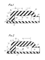
- FIGURE 1 is a cross-sectional side elevational view of a self-sealing subcutaneous injection site;
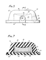
- FIGURE 2 is a cross-sectional side elevational view of another embodiment of a self-sealing subcutaneous injection site;
- FIGURE 3 is a side elevational view of the embodiment of the self-sealing subcutaneous injection site shown in FIGURE 1;
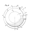
- FIGURE 4 is a top elevational view of the self-sealing subcutaneous injection site embodiment shown in FIGURE 1;
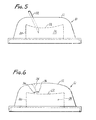
- FIGURE 5 is a side elevational view of the embodiment of the self-sealing injection site shown in FIGURE 1 and showing penetration by a needle cannula;
- FIGURE 6 is a side elevational view of the embodiment shown in FIGURE 5 with the needle cannula withdrawn; and
- FIGURE 7 is a side cross-sectional elevational view of still another embodiment of a self-sealing subcutaneous injection site.
- The self-sealing subcutaneous injection site will be described with regard to the accompanying drawings. In particular, FIGURE 1 shows an embodiment of a self-sealing
subcutaneous injection site 10. For facilitating description herein, the injection site will be referred to as the injection site. Theinjection site 10 has ahousing 12 which consists of an elastomeric material which is biocompatible with the human physiognomy. An acceptable material from which the housing can be constructed is silicone elastomer. The housing includes a generally dome-shaped wall 16 and abottom wall 14. The bottom wall can be constructed of a resilient material such as silicone elastomer or can be constucted of a material which is impenetrable to puncture by a needle cannula such as a polyethylene, polycarbonate and the like. When thebottom wall 14 is constructed of such an impenetrable material, it functions as a needle guard preventing a needle cannula, which is inserted into the housing to fill the chamber therein, from completely penetrating through the injection site. The bottom wall and dome-shaped wall are sealed together. - The dome-shaped wall of the housing defines an
inner chamber 18 having a volume for receiving fluid to be introduced or withdrawn from a patient's body following implantation of the injection site. The volume of the chamber can vary depending upon the contemplated end use for the injection site. With regard to FIGURES 1 and 3-6, the embodiment of the injection site shown therein has aninner chamber 18 formed bychamber sidewall 20 and chamberupper wall 22. Both thechamber sidewall 20 and chamberupper wall 22 are formed by at least a portion of the dome-shaped wall 16 of the housing. In the embodiment shown therein, thechamber sidewall 20 is generally a straight, vertically extending sidewall. As can be seen from the top view shown in FIGURE 6, thechamber sidewall 20 extends in a circle, forming a generallycylindrical chamber 18. Thechamber 18 can have geometric configurations other than cylindrical. - The chamber
upper wall 22 has a generally convex shape with the upper wall convex in regard to thechamber 18. The outer surface of the dome-shapedwall 16, at least at the upper surface generally designated as area A1 in FIGURE 1, has a generally or substantiallyflat surface 17. The geometric shape of the dome-shaped wall in the area Al, including the convex surface and chamberupper wall 22, combine with the durometer of the resilient material to provide compressive forces within the dome-shaped wall such that such forces can close a puncture extending through the dome-shaped wall. The self-sealing capability of the injection site herein is illustrated in FIGURES 5 and 6. - With regard to FIGURES 5 and 6, the embodiment of the injection site shown in FIGURE 1 is illustrated in a side elevational view. FIGURE 5 shows the injection site being punctured with a
needle cannula 32 which penetrates the dome-shapedwall 16 and extends into theinner chamber 18. A syringe (not shown) filled with a fluid to be introduced to the chamber can be connected to the needle cannula. As the dome-shaped wall is constructed of a resilient material, it can be punctured by the needle cannula. Using the syringe, fluid is introduced to theinner chamber 18. As fluid is introduced to the chamber, the fluid creates a pressure within the chamber, which pressure is exerted against the walls of the inner chamber. The pressure exerted against the chamberupper wall 22 forces the upper wall outwardly. Upon withdrawal of theneedle cannula 32, thepuncture 34 is closed and effectively sealed against fluid flow by the elastomeric properties of the material comprising the dome-shapedwall 16 and the compressive forces in the dome-shaped wall as a result of its structure. Such compressive forces are shown by thevectors 36 which arise as a result of the fluid pressure exerted against the convex chamberupper wall 22 which causes the chamber upper wall to lose its convexity and thereby exert a closing pressure against thepuncture 34 effectively sealing the puncture at especially its innermost portion near the chamberupper wall 22. That is, as the chamber is pressurized by the fluid the elastic dome-shaped wall is compressed. This compression is greatest at the inside surface such as the chamberupper wall 22. The compression and resulting material deformation causes the puncture to be effectively sealed along the chamberupper wall 22. - The embodiment shown in FIGURES 1 and 3-6 can be used in situations where there is a strong likelihood that the chamber will be filled by penetrating the dome-shaped wall of the injection site in the area designated as a Al on FIGURE 1. Such an embodiment provides an injection site which can be repeatedly punctured by a needle cannula while introducing fluid into the inner chamber, but which retains such fluid and greatly inhibits leaking of such fluid into the surrounding tissue. In addition, such a device can be used for infusing fluids into pressurized areas which may be experienced in the body such as in the circulatory system.
- In some instances, it is desirable to provide an injection site which can be punctured with a needle cannula in areas other than along the upper surface. For example, the embodiment shown in FIGURES 1 and 3-6 has a generally vertically extending
chamber sidewall 20. The sidewall and the corresponding area are designated as A3 in FIGURE 1 along with the upper corner between the chamber sidewall and chamber upper wall in the area generally designated as A2. During filling of thechamber 18 and pressurization of the chamber, thechamber sidewall 20 and corner area experience a tensioning and resulting wall strain. The material deformation through such tensioning causes any puncture extending the corresponding areas A2 and A3 to open along the inside surface which may take the shape of a concave surface at such areas. Upon such an occurrence, the surface adhesion of the elastomer along the puncture is easily overcome and leakage of the fluid from the chamber can occur through such puncture. The surfaces of the edge radius between the chamber upper wall and chamber sidewall and the chamber sidewall surface in the tangential (or horizontal) direction can be tensioned upon achieving high pressures within the chamber. The edge radius region can go into tension because of circumferential stresses and due to its concave surface. The chamber sidewall surface can go into tension tangentially because of the circumferential stress upon pressurization. These undesirable edge and chamber sidewall deformations can be lessened by constructing the embodiment shown in FIGURE 2 or by providing a cuff of reinforcing material such as Dacron, Nylon and the like extending around and imbedded in the chamber sidewall as is shown in FIGURE 7. The high modulus Dacron material prevents significant hoop strain at pressures which can be realized in the chamber. - With regard to FIGURE 7, another embodiment of the self-sealing subcutaneous injection site is illustrated. In the embodiment shown in FIGURE 7, the injection site has the structure substantially equivalent to that of the embodiment shown in FIGURE 1.
Injection site 38 of FIGURE 7 includes ahousing 40 having a resilient dome-shapedwall 42. The upperouter surface 43 of the dome-shaped wall is generally flat. The housing includes abottom wall 44 which can be sealed to the dome-shaped wall to form with the dome-shaped wall andinterior chamber 46. The interior 46 has a convex chamberupper wall 48 and achamber sidewall 50. Imbedded within the chamber sidewall is a reinforcing material such as a reinforcing mesh which can be constructed of Dacron, Nylon and the like. The reinforcingcuff 52 substantially prevents distortion of the sidewall, thereby assisting the sidewall in closing or sealing any punctures which extend therethrough. That is, the reinforcing cuff prevents distortion of the sidewall due to increased pressures which can occur in theinner chamber 46. Theinjection site 38 also can include an outwardly extendingflange 54. Also in the embodiment shown in FIGURE 7, the injection site therein includes aseparate needle guard 56 which is constructed of a material impermeable to puncture by a needle cannula. theneedle guard 56 is positioned along thebottom wall 44 within theinterior chamber 46. The needle guard can be supported and spaced from the bottom wall bylegs 58. - In the embodiment shown in FIGURE 2, elements that are the same as the elements of the embodiment shown in FIGURE 1 are shown using the same numbers. The embodiment shown in FIGURE 2 is identical to that of FIGURE 1 with the exception that the
chamber sidewall 21 has a convex configuration as opposed to the generally straight-walled chamber sidewall 20 of the embodiment in FIGURE 1. Such a convex structure along the chamber sidewall performs in much the same manner as above described with regard to the convex chamberupper wall 22 in the first embodiment. That is, the embodiment shown in FIGURE 2 can be repeatedly punctured either through the area shown as Al or A3 in FIGURE 2 and maintain its self-sealing capability. The only area remaining on the injection site wherein the greatest beneficial properties of the chamber wall structures is not realized is in the area designated as A2. The likelihood of puncturing such a small area with a needle cannula is reduced in view of the much greater areas in the areas designated Al and A3. - The embodiment shown in FIGURE 2 as well as that in FIGURE 1 can be used for implanting in high pressure situations such as accessing arterial blood or as an injection site for inflating skin expansion bladders. The embodiment shown in FIGURE 2 can provide for widely angled puncture positions for a syringe needle cannula used to introduce fluid into the
inner chamber 18. - Again with regard to both embodiments shown in the accompanying drawings, the housing includes a
conduit 24 which can be a cylindrical conduit integrally formed with the dome-shapedwall 16. Theconduit 24 provides a fluid-flow passageway 26 for providing fluid flow to and from the chamber. The fluid-flow passageway 26 can receive a tubing connector for connecting the injection site to a catheter or other tubing so that fluid introduced to the inner chamber can be delivered through such tubing to a site within the patient. - The housing can include an outwardly extending
flange 28. The housing can also be constructed in any geometric configuration, but in the preferred embodiment a circular configuration as is shown in FIGURE 4 is utilized. As can be seen in the drawings and especially in FIGURE 4, the outwardly extendingflange 28 extends around the periphery of the injection site. The flange can extend around only portions of the periphery of the injection site. One purpose of the flange is to provide for attachment of the injection site to a location within a patient. For example, the flange includessuture sites 30 through which sutures can be taken to fix the injection site subcutaneously within a patient. Other techniques for fixing the injection site within the patient can be used such as using surgical staples. Thesuture sites 30 can be apertures opening through the outwardly extending flange or can merely be areas along the flange of lesser thickness than the flange itself such that such suture sites can be easily penetrated by a surgical needle while suturing. - As stated above, various geometric shapes can be employed in constructing the injection site herein as long as the inner chamber is constructed as described, namely providing the chamber wall most likely to be punctured with a convex structure. In the preferred embodiment, the injection site has the outer configuration with a rather flat
upper surface 17 on the dome-shapedwall 16 as is shown in FIGURES 1 and 2. Such a configuration provides, upon fluid pressurization of the chamber, a direction of expansion for the convex chamber upper wall. - The size of the injection site can be modified according to the requirements for the treatment technique to which the injection site is being used. That is, the size can be varied to provide for palpation, different needle sizes, number of injections and expected back pressures in order to accomplish the desired resealing characteristics. In this manner, the injection site can be modified to meet the demands for placement into different body structures such as intrathecal, venous, arterial, intramuscular, and the like.
- Integral rigid connectors can be incorporated into the injection site by fitting such connectors into the
fluid passageway 26 to provide and simplify attachment of catheters and tubing. The injection site or portions thereof can be made radiopaque by incorporating materials having a radiopactiy during molding or manufacture of the injection site. By using radiopaque materials, the position of the device can be verified postoperatively. - The utility and beneficial properties of an injection site made in conformity with the invention herein was demonstrated in a series of tests wherein injection sites were repeatedly punctured. The tests were designed to determine the efficacy of injection sites and their ability to reseal after repeated needle puncture and for their use against transient pressures as high as 200 centimeters of water which is comparable to a high arterial blood pressure.
- The test technique was performed using each injection site dome configuration by puncturing each injection site up to the indicated number of punctures with a needle cannula that was either 19 gauge or 21 gauge as indicated having a regular bevel. The punctures were randomly distributed over the area of the injection site with the indicated areas being those areas as shown and designated in FIGURES 1 and 2. The injection sites were also tested for fluid leak rate from the inner chamber at a pressure of 200 centimeters of water. The injection site chambers were pressurized to 200 centimeters water pressure and the amount of extruded fluid was determined by soaking up the beads of fluid with a tared piece of absorbent paper toweling which was subsequently weighed to determine the amount of fluid.
- In the first series of tests, three injection sites were tested. The injection sites tested basically had the structure as shown in FIGURE 1 with the following limitations. The injection site designated as "A" was substantially identical to the embodiment shown in FIGURE 1; the injection site designated as "B" was substantially similar to the injection site shown in FIGURE 1 with the exception that the chamber sidewall was concave; and the injection site identified as "C" was substantially the same in all material aspects as the injection site shown in FIGURE 2. The injection sites were punctured in the following pattern of puncture distribution: 25 punctures in the top region generally designated area Al of FIGURE 1; 10 punctures in the edge region generally designated area A2; and 200 punctures in the side region generally designated area A3. For the punctures in the side region A3, the area punctured included the one-half of the injection site opposite the fluid-flow passageway. That is, the one-half of the injection site as if a diameter were drawn separating the injection site along the
line 38 as shown in FIGURE 4. The following results shown in Table I were obtained with the pressure readings in centimeters of water:
- From the above data it can be readily seen that the three injection site configurations provide injection sites which can be repeatedly punctured through area Al and maintain effective sealing even under high pressures in the chambers of the respective injection sites. The injection site C can be used when punctured repeatedly in area A3 and maintain effective sealing.
- When the above three configurations of injection sites were tested by pressurizing the chambers up to 200 centimeters of water pressure, the resultant leakage following the 235 punctures is as shown in the following table:

- The average leak rate in milliliters per hour for the three injection sites were A, 2.60; B, 2.32; and C, 1.74.
- The following tests using the above described techniques were also performed to determine leak pressures around and along various areas of an injection site having the structure shown in the embodiment in FIGURE 2. Six different injection sites were tested. Punctures were made using either a 21 gauge or a 19 gauge hypodermic needle having a regular bevel. The goals of the tests on such six injection sites were to determine the internal pressure which would cause leakage of the hypodermic needle punctures in specific areas on the injection site dome. The domes were repeatedly punctured, and the resulting pressure required to form a fluid bead on the surface of each injection site in centimeters of water recorded for the number of punctures. In the first section of the following table, the injection site was randomly punctured with 25 punctures in the area A1, 10 punctures in the area A2, and values determined for 10, 25 and 100 punctures in the area A3. The second portion of the table shows the results upon puncturing one quadrant of the injection site with 25 punctures in each of the areas A, and A2. The third section of the table provides the results of minimum leak pressures determined for the injection site after all of the punctures were made. The leak pressures were recorded for leaks only in the areas most recently punctured.

- As can be seen from the above table, the injection site structure performed very well with pressures requiring greater than 200 centimeters of water in order to form a bead on the surface of the injection site and 200 centimeters of water would be considered a high arterial blood pressure.
- In the above description, a specific example has been used to describe the injection site herein. However, it is understood by those skilled in the art that certain modifications can be made to this example without departing from the spirit and scope of the invention.
Claims (20)
Priority Applications (1)
| Application Number | Priority Date | Filing Date | Title |
|---|---|---|---|
| AT84307357T ATE41871T1 (en) | 1983-11-07 | 1984-10-25 | SELF-CLOSING SUBCUTANEOUS INJECTION SITE. |
Applications Claiming Priority (2)
| Application Number | Priority Date | Filing Date | Title |
|---|---|---|---|
| US06/549,092 US4543088A (en) | 1983-11-07 | 1983-11-07 | Self-sealing subcutaneous injection site |
| US549092 | 1983-11-07 |
Publications (3)
| Publication Number | Publication Date |
|---|---|
| EP0141625A2 true EP0141625A2 (en) | 1985-05-15 |
| EP0141625A3 EP0141625A3 (en) | 1986-04-30 |
| EP0141625B1 EP0141625B1 (en) | 1989-04-05 |
Family
ID=24191627
Family Applications (1)
| Application Number | Title | Priority Date | Filing Date |
|---|---|---|---|
| EP84307357A Expired EP0141625B1 (en) | 1983-11-07 | 1984-10-25 | Self-sealing subcutaneous injection site |
Country Status (7)
| Country | Link |
|---|---|
| US (1) | US4543088A (en) |
| EP (1) | EP0141625B1 (en) |
| JP (1) | JPS60114254A (en) |
| AT (1) | ATE41871T1 (en) |
| CA (1) | CA1222176A (en) |
| DE (1) | DE3477544D1 (en) |
| ZA (1) | ZA848120B (en) |
Cited By (3)
| Publication number | Priority date | Publication date | Assignee | Title |
|---|---|---|---|---|
| FR2582221A1 (en) * | 1985-05-21 | 1986-11-28 | Applied Precision Ltd | IMPLANTABLE CHRONIC INJECTION DEVICE FOR A SUBSTANCE, ESPECIALLY THERAPEUTIC |
| FR2586569A1 (en) * | 1985-09-04 | 1987-03-06 | Ahs France Laboratoires | Implantable injection site |
| US4762517A (en) * | 1986-09-18 | 1988-08-09 | Healthcare Technologies, Inc. | Subcutaneously-implanted drug delivery system for intravenous injections, and the like |
Families Citing this family (222)
| Publication number | Priority date | Publication date | Assignee | Title |
|---|---|---|---|---|
| US4738657A (en) * | 1985-09-30 | 1988-04-19 | Mcghan Medical Corporation | Self-sealing injection reservoir |
| US4840615A (en) * | 1985-09-30 | 1989-06-20 | Mcghan Medical Corporation | Self-sealing injection reservoir |
| US4798584A (en) * | 1985-09-30 | 1989-01-17 | Mcghan Medical Corporation | Self-sealing injection reservoir |
| US4767410A (en) * | 1985-12-16 | 1988-08-30 | Surgical Engineering Associates, Inc. | Implantable infusion port |
| US4710174A (en) * | 1985-12-16 | 1987-12-01 | Surgical Engineering Associates, Inc. | Implantable infusion port |
| US4673394A (en) * | 1986-01-17 | 1987-06-16 | Strato Medical Corporation | Implantable treatment reservoir |
| US4662357A (en) * | 1986-01-21 | 1987-05-05 | Dow Corning Corporation | Inflatable surgical implant with variable inflation position |
| US4695273A (en) * | 1986-04-08 | 1987-09-22 | I-Flow Corporation | Multiple needle holder and subcutaneous multiple channel infusion port |
| JPS6346171A (en) * | 1986-06-06 | 1988-02-27 | 旭光学工業株式会社 | Support of medical device stayed in living body |
| US4802885A (en) * | 1986-06-17 | 1989-02-07 | Medical Engineering Corporation | Self sealing subcutaneous infusion and withdrawal device |
| US4781695A (en) * | 1986-07-11 | 1988-11-01 | Dalton Michael J | Implantable fluid dispenser |
| US4704103A (en) * | 1986-08-21 | 1987-11-03 | Burron Medical Inc. | Implantable catheter means |
| US4904241A (en) * | 1986-10-16 | 1990-02-27 | Medical Engineering Corp. | Septum with a needle stop at the fluid transfer port |
| US4804054A (en) * | 1987-06-01 | 1989-02-14 | Intelligent Medicine, Inc. | Device and method for precise subcutaneous placement of a medical instrument |
| US4886501A (en) * | 1987-08-25 | 1989-12-12 | Shiley Infusaid Inc. | Implantable device |
| EP0309092B1 (en) * | 1987-08-25 | 1992-12-09 | Infusaid, Inc. | Implantable device |
| US5135489A (en) * | 1988-01-25 | 1992-08-04 | Baxter International Inc. | Pre-slit injection site and tapered cannula |
| US4915690A (en) * | 1988-02-02 | 1990-04-10 | C. R. Bard, Inc. | Micro-injection port |
| US5108377A (en) * | 1988-02-02 | 1992-04-28 | C.R. Bard, Inc. | Micro-injection port |
| US4898585A (en) * | 1988-05-18 | 1990-02-06 | Baxter Healthcare Corporation | Implantable patient-activated fluid delivery device with bolus injection port |
| US4898583A (en) * | 1988-05-18 | 1990-02-06 | Baxter Healthcare Corporation | Implantable patient-activated fluid delivery device and outlet valve therefor |
| US4898584A (en) * | 1988-05-18 | 1990-02-06 | Baxter Healthcare Corporation | Implantable patient-activated fluid delivery device |
| US4857053A (en) * | 1988-08-29 | 1989-08-15 | Dalton Michael J | Matrix septum |
| US4908029A (en) * | 1989-04-25 | 1990-03-13 | Medical Engineering Corporation | Flexible needle stop |
| US5137529A (en) * | 1990-02-20 | 1992-08-11 | Pudenz-Schulte Medical Research Corporation | Injection port |
| US5226879A (en) * | 1990-03-01 | 1993-07-13 | William D. Ensminger | Implantable access device |
| US5263930A (en) * | 1990-03-01 | 1993-11-23 | William D. Ensminger | Implantable access devices |
| US5057084A (en) * | 1990-03-01 | 1991-10-15 | The Regents Of The University Of Michigan | Implantable infusion device |
| US5053013A (en) * | 1990-03-01 | 1991-10-01 | The Regents Of The University Of Michigan | Implantable infusion device |
| US5356381A (en) * | 1990-03-01 | 1994-10-18 | Ensminger William D | Implantable access devices |
| US5350360A (en) * | 1990-03-01 | 1994-09-27 | Michigan Transtech Corporation | Implantable access devices |
| US5281199A (en) * | 1990-03-01 | 1994-01-25 | Michigan Transtech Corporation | Implantable access devices |
| US5180365A (en) * | 1990-03-01 | 1993-01-19 | Ensminger William D | Implantable infusion device |
| US5554117A (en) * | 1990-03-01 | 1996-09-10 | Michigan Transtech Corporation | Implantable access devices |
| US5352204A (en) * | 1990-03-01 | 1994-10-04 | Ensminger William D | Implantable access devices |
| US5085644A (en) * | 1990-04-02 | 1992-02-04 | Pudenz-Schulte Medical Research Corporation | Sterilizable medication infusion device with dose recharge restriction |
| US5082005A (en) * | 1990-12-18 | 1992-01-21 | New England Deaconess Hospital | Surgical access device |
| US5112303A (en) * | 1991-05-02 | 1992-05-12 | Pudenz-Schulte Medical Research Corporation | Tumor access device and method for delivering medication into a body cavity |
| US5964803A (en) * | 1993-07-27 | 1999-10-12 | Pmt Corporation | Enhanced surface implant and method of manufacture |
| US6053901A (en) * | 1994-01-18 | 2000-04-25 | Vasca, Inc. | Subcutaneously implanted cannula and method for arterial access |
| US6042569A (en) * | 1994-01-18 | 2000-03-28 | Vasca, Inc. | Subcutaneously implanted cannula and methods for vascular access |
| US5807356A (en) * | 1994-01-18 | 1998-09-15 | Vasca, Inc. | Catheter with valve |
| US5562617A (en) * | 1994-01-18 | 1996-10-08 | Finch, Jr.; Charles D. | Implantable vascular device |
| US6287850B1 (en) * | 1995-06-07 | 2001-09-11 | Affymetrix, Inc. | Bioarray chip reaction apparatus and its manufacture |
| US5725493A (en) * | 1994-12-12 | 1998-03-10 | Avery; Robert Logan | Intravitreal medicine delivery |
| US5951512A (en) * | 1996-05-28 | 1999-09-14 | Horizon Medical Products, Inc. | Infusion port with modified drug reservoir |
| US5718682A (en) * | 1996-06-28 | 1998-02-17 | United States Surgical Corporation | Access port device and method of manufacture |
| US5935164A (en) * | 1997-02-25 | 1999-08-10 | Pmt Corporaton | Laminated prosthesis and method of manufacture |
| US6190352B1 (en) | 1997-10-01 | 2001-02-20 | Boston Scientific Corporation | Guidewire compatible port and method for inserting same |
| US5989206A (en) * | 1997-10-31 | 1999-11-23 | Biolink Corporation | Apparatus and method for the dialysis of blood |
| US6039712A (en) * | 1997-11-04 | 2000-03-21 | Terence M. Fogarty | Implantable injection port |
| US7559893B2 (en) | 1998-12-01 | 2009-07-14 | Atropos Limited | Wound retractor device |
| US7537564B2 (en) | 1998-12-01 | 2009-05-26 | Atropos Limited | Wound retractor device |
| EP1602333B1 (en) | 1998-12-01 | 2008-06-04 | Atropos Limited | A wound retractor device |
| WO2000033901A1 (en) * | 1998-12-07 | 2000-06-15 | Std Manufacturing, Inc. | Implantable vascular access device |
| US8177762B2 (en) | 1998-12-07 | 2012-05-15 | C. R. Bard, Inc. | Septum including at least one identifiable feature, access ports including same, and related methods |
| DE60041009D1 (en) | 1999-10-14 | 2009-01-15 | Atropos Ltd | SURGICAL WOUND RETRACTOR |
| US7540839B2 (en) | 1999-10-14 | 2009-06-02 | Atropos Limited | Wound retractor |
| US6764472B1 (en) * | 2000-01-11 | 2004-07-20 | Bard Access Systems, Inc. | Implantable refillable infusion device |
| US6962577B2 (en) * | 2000-04-26 | 2005-11-08 | Std Manufacturing, Inc. | Implantable hemodialysis access device |
| US6478783B1 (en) | 2000-05-26 | 2002-11-12 | H. Robert Moorehead | Anti-sludge medication ports and related methods |
| WO2002034108A2 (en) | 2000-10-19 | 2002-05-02 | Applied Medical Resources Corporation | Surgical access apparatus and method |
| US6648853B1 (en) * | 2000-10-31 | 2003-11-18 | Agilent Technologies Inc. | Septum |
| WO2003015848A1 (en) | 2001-08-14 | 2003-02-27 | Applied Medical Resources Corporation | Access sealing apparatus and method |
| US6958037B2 (en) | 2001-10-20 | 2005-10-25 | Applied Medical Resources Corporation | Wound retraction apparatus and method |
| EP2340792B1 (en) | 2002-06-05 | 2012-05-09 | Applied Medical Resources Corporation | Wound retractor |
| US9271753B2 (en) | 2002-08-08 | 2016-03-01 | Atropos Limited | Surgical device |
| AU2003273510A1 (en) | 2002-09-19 | 2004-04-08 | Atropos Limited | A wound retractor system |
| US8574204B2 (en) | 2002-10-21 | 2013-11-05 | Angiodynamics, Inc. | Implantable medical device for improved placement and adherence in the body |
| US20050020884A1 (en) | 2003-02-25 | 2005-01-27 | Hart Charles C. | Surgical access system |
| US20040185421A1 (en) * | 2003-03-18 | 2004-09-23 | Cagenix, Inc. | Method of using a tissue contourer |
| US8029477B2 (en) * | 2003-12-19 | 2011-10-04 | Ethicon Endo-Surgery, Inc. | Applier with safety for implantable medical device |
| US7561916B2 (en) * | 2005-06-24 | 2009-07-14 | Ethicon Endo-Surgery, Inc. | Implantable medical device with indicator |
| US8715243B2 (en) | 2003-06-16 | 2014-05-06 | Ethicon Endo-Surgery, Inc. | Injection port applier with downward force actuation |
| US7862546B2 (en) * | 2003-06-16 | 2011-01-04 | Ethicon Endo-Surgery, Inc. | Subcutaneous self attaching injection port with integral moveable retention members |
| JP4067463B2 (en) * | 2003-07-18 | 2008-03-26 | トヨタ自動車株式会社 | Control device for hybrid vehicle |
| CA2533204A1 (en) | 2003-08-06 | 2005-02-17 | Applied Medical Resources Corporation | Surgical device with tack-free gel and method of manufacture |
| US7163510B2 (en) | 2003-09-17 | 2007-01-16 | Applied Medical Resources Corporation | Surgical instrument access device |
| US8162897B2 (en) | 2003-12-19 | 2012-04-24 | Ethicon Endo-Surgery, Inc. | Audible and tactile feedback |
| US8366687B2 (en) | 2004-01-06 | 2013-02-05 | Angio Dynamics | Injection access port with chamfered top hat septum design |
| US8277425B2 (en) | 2004-03-24 | 2012-10-02 | Navilyst Medical, Inc. | Dual lumen port with F-shaped connector |
| US20060084929A1 (en) * | 2004-07-13 | 2006-04-20 | Kenneth Eliasen | Infusion port |
| US7811266B2 (en) * | 2004-07-13 | 2010-10-12 | Std Med, Inc. | Volume reducing reservoir insert for an infusion port |
| US8246569B1 (en) | 2004-08-17 | 2012-08-21 | California Institute Of Technology | Implantable intraocular pressure drain |
| AU2004323123A1 (en) * | 2004-08-19 | 2006-03-16 | Compagnie Europeenne D'etude Et De Recherche De Dispositifs Pour L'implantation Par Laparoscopie | Implantable medical site |
| US7244270B2 (en) * | 2004-09-16 | 2007-07-17 | Evera Medical | Systems and devices for soft tissue augmentation |
| US7641688B2 (en) | 2004-09-16 | 2010-01-05 | Evera Medical, Inc. | Tissue augmentation device |
| US20060058890A1 (en) * | 2004-09-16 | 2006-03-16 | Lesh Michael D | Methods for soft tissue augmentation |
| EP1804695A1 (en) | 2004-10-11 | 2007-07-11 | Atropos Limited | An instrument access device |
| US10207095B2 (en) * | 2004-12-14 | 2019-02-19 | C. R. Bard, Inc. | Fast clear port |
| US9474888B2 (en) | 2005-03-04 | 2016-10-25 | C. R. Bard, Inc. | Implantable access port including a sandwiched radiopaque insert |
| US7947022B2 (en) * | 2005-03-04 | 2011-05-24 | C. R. Bard, Inc. | Access port identification systems and methods |
| US8029482B2 (en) | 2005-03-04 | 2011-10-04 | C. R. Bard, Inc. | Systems and methods for radiographically identifying an access port |
| WO2006096686A1 (en) * | 2005-03-04 | 2006-09-14 | C.R. Bard, Inc. | Access port identification systems and methods |
| US10307581B2 (en) | 2005-04-27 | 2019-06-04 | C. R. Bard, Inc. | Reinforced septum for an implantable medical device |
| EP1896117B1 (en) * | 2005-04-27 | 2011-01-12 | C.R.Bard, Inc. | Power injector system for injecting contrast media into an intravenous line |
| US8147455B2 (en) | 2005-04-27 | 2012-04-03 | C. R. Bard, Inc. | Infusion apparatuses and methods of use |
| US20060258994A1 (en) * | 2005-05-12 | 2006-11-16 | Avery Robert L | Implantable delivery device for administering pharmacological agents to an internal portion of a body |
| WO2006137768A1 (en) * | 2005-06-23 | 2006-12-28 | Gambro Lundia Ab | Implantable access device and method for preparing thereof |
| US7651483B2 (en) * | 2005-06-24 | 2010-01-26 | Ethicon Endo-Surgery, Inc. | Injection port |
| US7918844B2 (en) * | 2005-06-24 | 2011-04-05 | Ethicon Endo-Surgery, Inc. | Applier for implantable medical device |
| US20070073250A1 (en) * | 2005-07-08 | 2007-03-29 | Schneiter James A | Implantable port |
| WO2007010511A1 (en) | 2005-07-15 | 2007-01-25 | Atropos Limited | A wound retractor |
| WO2007019371A2 (en) * | 2005-08-04 | 2007-02-15 | Becton, Dickinson And Company | Injection fluid leakage collection system and method |
| ATE480278T1 (en) * | 2005-09-12 | 2010-09-15 | Unomedical As | INTRODUCTION SYSTEM FOR AN INFUSION SET WITH A FIRST AND SECOND SPRING UNIT |
| US20070067041A1 (en) * | 2005-09-16 | 2007-03-22 | Kotoske Thomas G | Inflatable facial implant and associated method |
| US20070066934A1 (en) * | 2005-09-19 | 2007-03-22 | Transport Pharmaceuticals, Inc. | Electrokinetic delivery system and methods therefor |
| US20070185432A1 (en) * | 2005-09-19 | 2007-08-09 | Transport Pharmaceuticals, Inc. | Electrokinetic system and method for delivering methotrexate |
| US20070078416A1 (en) * | 2005-10-04 | 2007-04-05 | Kenneth Eliasen | Two-piece inline vascular access portal |
| JP5132565B2 (en) | 2005-10-14 | 2013-01-30 | アプライド メディカル リソーシーズ コーポレイション | Method for manufacturing hand access instrument for laparoscopy |
| US20070088336A1 (en) * | 2005-10-17 | 2007-04-19 | Dalton Michael J | Implantable drug delivery depot for subcutaneous delivery of fluids |
| BRPI0505102A (en) * | 2005-11-22 | 2007-08-07 | Renato Samy Assad | Improvements introduced in pulmonary trunk bandage device |
| RU2419460C2 (en) | 2005-12-23 | 2011-05-27 | Уномедикал А/С | Injection device |
| US7708722B2 (en) * | 2006-01-10 | 2010-05-04 | Stealth Therapeutics, Inc. | Stabilized implantable vascular access port |
| US7608065B2 (en) * | 2006-01-30 | 2009-10-27 | Glenn Bradley J | Bone supported vascular access port |
| AU2007219546B8 (en) | 2006-02-28 | 2012-07-05 | Unomedical A/S | Inserter for infusion part and infusion part provided with needle protector |
| ATE497797T1 (en) * | 2006-03-14 | 2011-02-15 | Univ Southern California | MEMS DEVICE FOR DRUG RELEASE |
| WO2007120529A2 (en) * | 2006-03-31 | 2007-10-25 | Glenn Bradley J | Subcutaneous catheter retainer |
| MX2008015247A (en) | 2006-06-09 | 2008-12-15 | Unomedical As | Mounting pad. |
| CN101500626B (en) * | 2006-08-02 | 2012-08-22 | 优诺医疗有限公司 | Insertion device |
| KR20090037492A (en) | 2006-08-02 | 2009-04-15 | 우노메디컬 에이/에스 | Cannula and delivery device |
| US9642986B2 (en) | 2006-11-08 | 2017-05-09 | C. R. Bard, Inc. | Resource information key for an insertable medical device |
| US9265912B2 (en) | 2006-11-08 | 2016-02-23 | C. R. Bard, Inc. | Indicia informative of characteristics of insertable medical devices |
| AU2008209857A1 (en) * | 2007-02-02 | 2008-08-07 | Unomedical A/S | Injection site for injecting medication |
| WO2008124123A1 (en) * | 2007-04-05 | 2008-10-16 | Glenn Bradley J | Stabilized elongate implantable vascular access device |
| EP2146643A4 (en) | 2007-05-11 | 2012-05-30 | Applied Med Resources | Surgical retractor with gel pad |
| US8226552B2 (en) | 2007-05-11 | 2012-07-24 | Applied Medical Resources Corporation | Surgical retractor |
| US8657740B2 (en) | 2007-06-05 | 2014-02-25 | Atropos Limited | Instrument access device |
| US8187178B2 (en) | 2007-06-05 | 2012-05-29 | Atropos Limited | Instrument access device |
| US8257325B2 (en) | 2007-06-20 | 2012-09-04 | Medical Components, Inc. | Venous access port with molded and/or radiopaque indicia |
| AU2008266382B2 (en) | 2007-06-20 | 2013-06-27 | Unomedical A/S | A catheter and a method and an apparatus for making such catheter |
| US10702174B2 (en) * | 2007-06-27 | 2020-07-07 | Integra Lifesciences Corporation | Medical monitor user interface |
| US7731700B1 (en) | 2007-06-29 | 2010-06-08 | Walter Samuel Schytte | Subdermal injection port |
| EP2185224A1 (en) * | 2007-07-03 | 2010-05-19 | Unomedical A/S | Inserter having bistable equilibrium states |
| AU2008274311A1 (en) * | 2007-07-10 | 2009-01-15 | Unomedical A/S | Inserter having two springs |
| EP2180915B1 (en) | 2007-07-19 | 2017-10-04 | Medical Components, Inc. | Venous access port assembly with x-ray discernable indicia |
| US9610432B2 (en) | 2007-07-19 | 2017-04-04 | Innovative Medical Devices, Llc | Venous access port assembly with X-ray discernable indicia |
| US8209015B2 (en) * | 2007-10-09 | 2012-06-26 | Stealth Therapeutics, Inc. | Enhanced stability implantable medical device |
| US9579496B2 (en) | 2007-11-07 | 2017-02-28 | C. R. Bard, Inc. | Radiopaque and septum-based indicators for a multi-lumen implantable port |
| MX364408B (en) | 2007-12-20 | 2019-04-25 | Univ Southern California | APPARATUS and METHODS FOR DELIVERING THERAPEUTIC AGENTS. |
| DK2240220T3 (en) | 2008-01-03 | 2016-08-01 | Univ Southern California | Implantable devices for drug AND APPARATUS FOR refilling DEVICES |
| EP2237815B1 (en) | 2008-01-22 | 2020-08-19 | Applied Medical Resources Corporation | Surgical instrument access device |
| US20090198329A1 (en) | 2008-02-01 | 2009-08-06 | Kesten Randy J | Breast implant with internal flow dampening |
| US20110098652A1 (en) * | 2008-02-13 | 2011-04-28 | Unomedical A/S | Moulded Connection between Cannula and Delivery Part |
| RU2010137844A (en) | 2008-02-13 | 2012-03-20 | Уномедикал А/С (Dk) | SEAL BETWEEN THE CANULE PART AND BY PASSING A FUEL |
| EP2259816B1 (en) * | 2008-02-20 | 2015-10-21 | Unomedical A/S | Insertion device with horizontally moving part |
| NZ588818A (en) | 2008-04-17 | 2012-10-26 | Allergan Inc | Body implantable access port device activated by a cable mechanism |
| US9023063B2 (en) | 2008-04-17 | 2015-05-05 | Apollo Endosurgery, Inc. | Implantable access port device having a safety cap |
| US9849238B2 (en) | 2008-05-08 | 2017-12-26 | Minipumps, Llc | Drug-delivery pump with intelligent control |
| JP2011519695A (en) | 2008-05-08 | 2011-07-14 | リプレニッシュ パンプス, エルエルシー | Implantable drug delivery device and apparatus and method for filling the device |
| MX2010012213A (en) * | 2008-05-08 | 2011-05-03 | Minipumps Llc | Implantable pumps and cannulas therefor. |
| CN102202708B (en) | 2008-05-08 | 2015-01-21 | 迷你泵有限责任公司 | Drug-delivery pumps and methods of manufacture |
| US20110168294A1 (en) * | 2008-05-30 | 2011-07-14 | Claus Jakobsen | Reservoir filling device |
| EP2296729A1 (en) * | 2008-07-07 | 2011-03-23 | Unomedical A/S | Inserter for transcutaneous device |
| US8075536B2 (en) | 2008-09-09 | 2011-12-13 | Navilyst Medical, Inc. | Power injectable port identification |
| AU2009303470B2 (en) | 2008-10-13 | 2015-04-23 | Applied Medical Resources Corporation | Single port access system |
| WO2010051494A1 (en) | 2008-10-31 | 2010-05-06 | C.R. Bard, Inc. | Systems and methods for identifying an acess port |
| US11890443B2 (en) | 2008-11-13 | 2024-02-06 | C. R. Bard, Inc. | Implantable medical devices including septum-based indicators |
| US8932271B2 (en) | 2008-11-13 | 2015-01-13 | C. R. Bard, Inc. | Implantable medical devices including septum-based indicators |
| WO2010072664A1 (en) | 2008-12-22 | 2010-07-01 | Unomedical A/S | Medical device comprising adhesive pad |
| US8375955B2 (en) | 2009-02-06 | 2013-02-19 | Atropos Limited | Surgical procedure |
| EP2451512A1 (en) * | 2009-07-07 | 2012-05-16 | C.R. Bard Inc. | Extensible internal bolster for a medical device |
| CN102470211B (en) | 2009-07-30 | 2014-05-07 | 犹诺医药有限公司 | Inserter device with horizontal moving part |
| RU2012108579A (en) | 2009-08-07 | 2013-09-20 | Уномедикал А/С | DELIVERY DEVICE WITH SENSOR AND ONE OR MULTIPLE CANULES |
| MX2012002063A (en) * | 2009-08-18 | 2012-08-01 | Minipumps Llc | Electrolytic drug-delivery pump with adaptive control. |
| US8506532B2 (en) | 2009-08-26 | 2013-08-13 | Allergan, Inc. | System including access port and applicator tool |
| US8708979B2 (en) * | 2009-08-26 | 2014-04-29 | Apollo Endosurgery, Inc. | Implantable coupling device |
| US8715158B2 (en) | 2009-08-26 | 2014-05-06 | Apollo Endosurgery, Inc. | Implantable bottom exit port |
| WO2011033495A1 (en) | 2009-09-17 | 2011-03-24 | Atropos Limited | An instrument access device |
| JP2013510652A (en) | 2009-11-17 | 2013-03-28 | シー・アール・バード・インコーポレーテッド | Overmolded access port including locking feature and identification feature |
| US8377034B2 (en) | 2009-12-04 | 2013-02-19 | Std Med, Inc. | Vascular access port |
| US20110196195A1 (en) | 2010-02-05 | 2011-08-11 | Allergan, Inc. | Implantable subcutaneous access port |
| US8882728B2 (en) | 2010-02-10 | 2014-11-11 | Apollo Endosurgery, Inc. | Implantable injection port |
| JP2013523233A (en) | 2010-03-30 | 2013-06-17 | ウノメディカル アクティーゼルスカブ | Medical device |
| US8992415B2 (en) | 2010-04-30 | 2015-03-31 | Apollo Endosurgery, Inc. | Implantable device to protect tubing from puncture |
| US20110270025A1 (en) | 2010-04-30 | 2011-11-03 | Allergan, Inc. | Remotely powered remotely adjustable gastric band system |
| US20110270021A1 (en) | 2010-04-30 | 2011-11-03 | Allergan, Inc. | Electronically enhanced access port for a fluid filled implant |
| US10420923B1 (en) | 2010-08-10 | 2019-09-24 | Amiram Katz | Method and device for intrathecal administering of immunoglobulin |
| US20120041258A1 (en) | 2010-08-16 | 2012-02-16 | Allergan, Inc. | Implantable access port system |
| US20120065460A1 (en) | 2010-09-14 | 2012-03-15 | Greg Nitka | Implantable access port system |
| EP2433663A1 (en) | 2010-09-27 | 2012-03-28 | Unomedical A/S | Insertion system |
| EP2621348B1 (en) | 2010-10-01 | 2019-06-12 | Applied Medical Resources Corporation | Natural orifice surgery system |
| US9289115B2 (en) | 2010-10-01 | 2016-03-22 | Applied Medical Resources Corporation | Natural orifice surgery system |
| EP2436412A1 (en) | 2010-10-04 | 2012-04-04 | Unomedical A/S | A sprinkler cannula |
| WO2012064881A2 (en) | 2010-11-09 | 2012-05-18 | Frank Prosl | Hemodialysis access system |
| USD682416S1 (en) | 2010-12-30 | 2013-05-14 | C. R. Bard, Inc. | Implantable access port |
| USD676955S1 (en) | 2010-12-30 | 2013-02-26 | C. R. Bard, Inc. | Implantable access port |
| US10286146B2 (en) | 2011-03-14 | 2019-05-14 | Minipumps, Llc | Implantable drug pumps and refill devices therefor |
| US9603997B2 (en) | 2011-03-14 | 2017-03-28 | Minipumps, Llc | Implantable drug pumps and refill devices therefor |
| US9919099B2 (en) | 2011-03-14 | 2018-03-20 | Minipumps, Llc | Implantable drug pumps and refill devices therefor |
| ES2822115T3 (en) | 2011-05-10 | 2021-04-29 | Applied Med Resources | Wound retractor device |
| US8821373B2 (en) | 2011-05-10 | 2014-09-02 | Apollo Endosurgery, Inc. | Directionless (orientation independent) needle injection port |
| US8801597B2 (en) | 2011-08-25 | 2014-08-12 | Apollo Endosurgery, Inc. | Implantable access port with mesh attachment rivets |
| US11197689B2 (en) | 2011-10-05 | 2021-12-14 | Unomedical A/S | Inserter for simultaneous insertion of multiple transcutaneous parts |
| EP2583715A1 (en) | 2011-10-19 | 2013-04-24 | Unomedical A/S | Infusion tube system and method for manufacture |
| US9199069B2 (en) | 2011-10-20 | 2015-12-01 | Apollo Endosurgery, Inc. | Implantable injection port |
| US9440051B2 (en) | 2011-10-27 | 2016-09-13 | Unomedical A/S | Inserter for a multiplicity of subcutaneous parts |
| US8858421B2 (en) | 2011-11-15 | 2014-10-14 | Apollo Endosurgery, Inc. | Interior needle stick guard stems for tubes |
| US9089395B2 (en) | 2011-11-16 | 2015-07-28 | Appolo Endosurgery, Inc. | Pre-loaded septum for use with an access port |
| US9707339B2 (en) | 2012-03-28 | 2017-07-18 | Angiodynamics, Inc. | High flow rate dual reservoir port system |
| US9713704B2 (en) | 2012-03-29 | 2017-07-25 | Bradley D. Chartrand | Port reservoir cleaning system and method |
| JP6487339B2 (en) | 2013-01-23 | 2019-03-20 | シー・アール・バード・インコーポレーテッドC R Bard Incorporated | Low profile access port |
| US11464960B2 (en) | 2013-01-23 | 2022-10-11 | C. R. Bard, Inc. | Low-profile single and dual vascular access device |
| US11420033B2 (en) | 2013-01-23 | 2022-08-23 | C. R. Bard, Inc. | Low-profile single and dual vascular access device |
| US9636070B2 (en) | 2013-03-14 | 2017-05-02 | DePuy Synthes Products, Inc. | Methods, systems, and devices for monitoring and displaying medical parameters for a patient |
| KR102300866B1 (en) | 2013-03-15 | 2021-09-13 | 어플라이드 메디컬 리소시스 코포레이션 | Mechanical gel surgical access device |
| US10166321B2 (en) | 2014-01-09 | 2019-01-01 | Angiodynamics, Inc. | High-flow port and infusion needle systems |
| US10369345B2 (en) | 2014-03-31 | 2019-08-06 | Versago Vascular Access, Inc. | Medical access port, systems and methods of use thereof |
| US9764124B2 (en) | 2014-03-31 | 2017-09-19 | Versago Vascular Access, Inc. | Vascular access port |
| EP3125985B1 (en) | 2014-04-03 | 2021-09-22 | Versago Vascular Access, Inc. | Devices and methods for installation and removal of a needle tip of a needle |
| EP3169510B1 (en) | 2014-07-18 | 2018-10-03 | Applied Medical Resources Corporation | Method for manufacturing gels having permanent tack free coatings |
| ES2930777T3 (en) | 2014-08-15 | 2022-12-21 | Applied Med Resources | Natural orifice surgery system |
| US9949730B2 (en) | 2014-11-25 | 2018-04-24 | Applied Medical Resources Corporation | Circumferential wound retraction with support and guidance structures |
| WO2016100945A1 (en) | 2014-12-18 | 2016-06-23 | Versago Vascular Access, Inc. | Devices, systems and methods for removal and replacement of a catheter for an implanted access port |
| JP6837971B2 (en) | 2014-12-18 | 2021-03-03 | ヴェルサゴ ヴァスキュラー アクセス インコーポレイテッド | Catheter patency system and method |
| JP6879946B2 (en) | 2015-07-14 | 2021-06-02 | ヴェルサゴ ヴァスキュラー アクセス インコーポレイテッド | Medical access ports, transport devices and how to use them |
| ES2937400T3 (en) | 2015-09-15 | 2023-03-28 | Applied Med Resources | Surgical Robotic Access System |
| JP6953402B2 (en) | 2015-10-07 | 2021-10-27 | アプライド メディカル リソーシーズ コーポレイション | Wound retractor with multi-segment outer ring |
| US10674896B2 (en) | 2016-09-12 | 2020-06-09 | Applied Medical Resources Corporation | Surgical robotic access system for irregularly shaped robotic actuators and associated robotic surgical instruments |
| WO2019040907A1 (en) * | 2017-08-24 | 2019-02-28 | Sutherland Spencer D | Dispensing device |
| USD870264S1 (en) | 2017-09-06 | 2019-12-17 | C. R. Bard, Inc. | Implantable apheresis port |
| EP3727558A4 (en) | 2017-12-21 | 2022-01-19 | Versago Vascular Access, Inc. | Medical access ports, transfer devices and methods of use thereof |
Citations (4)
| Publication number | Priority date | Publication date | Assignee | Title |
|---|---|---|---|---|
| US3831583A (en) * | 1971-03-05 | 1974-08-27 | Univ California | Implantable bulb for inflation of surgical implements |
| EP0068815A1 (en) * | 1981-06-30 | 1983-01-05 | BAXTER INTERNATIONAL INC. (a Delaware corporation) | Low profile shunt system |
| US4400169A (en) * | 1980-10-27 | 1983-08-23 | University Of Utah Research Foundation | Subcutaneous peritoneal injection catheter |
| US4405305A (en) * | 1980-10-27 | 1983-09-20 | University Of Utah Research Foundation | Subcutaneous peritoneal injection catheter |
-
1983
- 1983-11-07 US US06/549,092 patent/US4543088A/en not_active Expired - Fee Related
-
1984
- 1984-10-17 ZA ZA848120A patent/ZA848120B/en unknown
- 1984-10-25 AT AT84307357T patent/ATE41871T1/en not_active IP Right Cessation
- 1984-10-25 EP EP84307357A patent/EP0141625B1/en not_active Expired
- 1984-10-25 DE DE8484307357T patent/DE3477544D1/en not_active Expired
- 1984-11-06 JP JP59232551A patent/JPS60114254A/en active Pending
- 1984-11-07 CA CA000467221A patent/CA1222176A/en not_active Expired
Patent Citations (4)
| Publication number | Priority date | Publication date | Assignee | Title |
|---|---|---|---|---|
| US3831583A (en) * | 1971-03-05 | 1974-08-27 | Univ California | Implantable bulb for inflation of surgical implements |
| US4400169A (en) * | 1980-10-27 | 1983-08-23 | University Of Utah Research Foundation | Subcutaneous peritoneal injection catheter |
| US4405305A (en) * | 1980-10-27 | 1983-09-20 | University Of Utah Research Foundation | Subcutaneous peritoneal injection catheter |
| EP0068815A1 (en) * | 1981-06-30 | 1983-01-05 | BAXTER INTERNATIONAL INC. (a Delaware corporation) | Low profile shunt system |
Non-Patent Citations (1)
| Title |
|---|
| THE AMERICAN JOURNAL OF MEDICINE, vol. 73, December 1982, pages 843-844; J. GYVES et al.: "Totally implanted system for intravenous chemotherapy in patients with cancer" * |
Cited By (4)
| Publication number | Priority date | Publication date | Assignee | Title |
|---|---|---|---|---|
| FR2582221A1 (en) * | 1985-05-21 | 1986-11-28 | Applied Precision Ltd | IMPLANTABLE CHRONIC INJECTION DEVICE FOR A SUBSTANCE, ESPECIALLY THERAPEUTIC |
| EP0203633A1 (en) * | 1985-05-21 | 1986-12-03 | Applied Precision Limited | Implantable device for the regular injection of a therapeutic substance |
| FR2586569A1 (en) * | 1985-09-04 | 1987-03-06 | Ahs France Laboratoires | Implantable injection site |
| US4762517A (en) * | 1986-09-18 | 1988-08-09 | Healthcare Technologies, Inc. | Subcutaneously-implanted drug delivery system for intravenous injections, and the like |
Also Published As
| Publication number | Publication date |
|---|---|
| DE3477544D1 (en) | 1989-05-11 |
| EP0141625A3 (en) | 1986-04-30 |
| EP0141625B1 (en) | 1989-04-05 |
| US4543088A (en) | 1985-09-24 |
| ZA848120B (en) | 1985-06-26 |
| CA1222176A (en) | 1987-05-26 |
| JPS60114254A (en) | 1985-06-20 |
| ATE41871T1 (en) | 1989-04-15 |
Similar Documents
| Publication | Publication Date | Title |
|---|---|---|
| EP0141625B1 (en) | Self-sealing subcutaneous injection site | |
| US3831583A (en) | Implantable bulb for inflation of surgical implements | |
| US4217889A (en) | Flap development device and method of progressively increasing skin area | |
| US3730186A (en) | Adjustable implantable artery-constricting device | |
| EP1815881B2 (en) | Injection port | |
| CA2489732C (en) | Flexible injection port | |
| US4800901A (en) | Balloon-type Tissue expansion device | |
| US5647855A (en) | Self-healing diaphragm in a subcutaneous infusion port | |
| US4781695A (en) | Implantable fluid dispenser | |
| US5082005A (en) | Surgical access device | |
| US4692146A (en) | Multiple vascular access port | |
| US20050131383A1 (en) | Method for implanting flexible injection port | |
| JPS61268269A (en) | Manually operable embedddable apparatus for repeating and distributing administration amount of treating substance | |
| US4817637A (en) | Subcutaneous injection and withdrawal site | |
| US7101356B2 (en) | Implantable vascular access device | |
| US11813424B1 (en) | Inline injection port assembly | |
| JPS63296770A (en) | Subcutaneous embedding type reservoir | |
| CA1121553A (en) | Self-sealing valve for breast prosthesis | |
| AU2011205152B2 (en) | A method for implanting flexible injection port | |
| CN114306894A (en) | Lumbar puncture catheter balloon device | |
| Zierski et al. | Implantation of ports and pumps. Technique for intrathecal administration of drugs | |
| JPH11155958A (en) | Medicinal liquid injecting port |
Legal Events
| Date | Code | Title | Description |
|---|---|---|---|
| PUAI | Public reference made under article 153(3) epc to a published international application that has entered the european phase |
Free format text: ORIGINAL CODE: 0009012 |
|
| AK | Designated contracting states |
Designated state(s): AT BE CH DE FR GB IT LI LU NL SE |
|
| PUAL | Search report despatched |
Free format text: ORIGINAL CODE: 0009013 |
|
| AK | Designated contracting states |
Kind code of ref document: A3 Designated state(s): AT BE CH DE FR GB IT LI LU NL SE |
|
| 17P | Request for examination filed |
Effective date: 19861006 |
|
| RAP1 | Party data changed (applicant data changed or rights of an application transferred) |
Owner name: BAXTER TRAVENOL LABORATORIES, INC. |
|
| 17Q | First examination report despatched |
Effective date: 19880212 |
|
| RAP1 | Party data changed (applicant data changed or rights of an application transferred) |
Owner name: BAXTER INTERNATIONAL INC. |
|
| GRAA | (expected) grant |
Free format text: ORIGINAL CODE: 0009210 |
|
| AK | Designated contracting states |
Kind code of ref document: B1 Designated state(s): AT BE CH DE FR GB IT LI LU NL SE |
|
| REF | Corresponds to: |
Ref document number: 41871 Country of ref document: AT Date of ref document: 19890415 Kind code of ref document: T |
|
| ITF | It: translation for a ep patent filed |
Owner name: LENZI & C. |
|
| REF | Corresponds to: |
Ref document number: 3477544 Country of ref document: DE Date of ref document: 19890511 |
|
| ET | Fr: translation filed | ||
| PGFP | Annual fee paid to national office [announced via postgrant information from national office to epo] |
Ref country code: SE Payment date: 19890927 Year of fee payment: 6 |
|
| PGFP | Annual fee paid to national office [announced via postgrant information from national office to epo] |
Ref country code: FR Payment date: 19890928 Year of fee payment: 6 |
|
| PGFP | Annual fee paid to national office [announced via postgrant information from national office to epo] |
Ref country code: GB Payment date: 19890930 Year of fee payment: 6 |
|
| PGFP | Annual fee paid to national office [announced via postgrant information from national office to epo] |
Ref country code: AT Payment date: 19891009 Year of fee payment: 6 |
|
| PGFP | Annual fee paid to national office [announced via postgrant information from national office to epo] |
Ref country code: LU Payment date: 19891012 Year of fee payment: 6 |
|
| PGFP | Annual fee paid to national office [announced via postgrant information from national office to epo] |
Ref country code: BE Payment date: 19891013 Year of fee payment: 6 |
|
| ITTA | It: last paid annual fee | ||
| PG25 | Lapsed in a contracting state [announced via postgrant information from national office to epo] |
Ref country code: LU Free format text: LAPSE BECAUSE OF NON-PAYMENT OF DUE FEES Effective date: 19891031 |
|
| PGFP | Annual fee paid to national office [announced via postgrant information from national office to epo] |
Ref country code: NL Payment date: 19891031 Year of fee payment: 6 |
|
| PGFP | Annual fee paid to national office [announced via postgrant information from national office to epo] |
Ref country code: DE Payment date: 19891229 Year of fee payment: 6 |
|
| PGFP | Annual fee paid to national office [announced via postgrant information from national office to epo] |
Ref country code: CH Payment date: 19900104 Year of fee payment: 6 |
|
| PLBI | Opposition filed |
Free format text: ORIGINAL CODE: 0009260 |
|
| 26 | Opposition filed |
Opponent name: FRESENIUS AG Effective date: 19891229 |
|
| NLR1 | Nl: opposition has been filed with the epo |
Opponent name: FRESENIUS AG. |
|
| PG25 | Lapsed in a contracting state [announced via postgrant information from national office to epo] |
Ref country code: GB Effective date: 19901025 Ref country code: AT Effective date: 19901025 |
|
| PG25 | Lapsed in a contracting state [announced via postgrant information from national office to epo] |
Ref country code: SE Effective date: 19901026 |
|
| PG25 | Lapsed in a contracting state [announced via postgrant information from national office to epo] |
Ref country code: LI Free format text: LAPSE BECAUSE OF NON-PAYMENT OF DUE FEES Effective date: 19901031 Ref country code: CH Free format text: LAPSE BECAUSE OF NON-PAYMENT OF DUE FEES Effective date: 19901031 Ref country code: BE Effective date: 19901031 |
|
| BERE | Be: lapsed |
Owner name: BAXTER INTERNATIONAL INC. Effective date: 19901031 |
|
| PG25 | Lapsed in a contracting state [announced via postgrant information from national office to epo] |
Ref country code: NL Effective date: 19910501 |
|
| NLV4 | Nl: lapsed or anulled due to non-payment of the annual fee | ||
| GBPC | Gb: european patent ceased through non-payment of renewal fee | ||
| REG | Reference to a national code |
Ref country code: CH Ref legal event code: PL |
|
| RDAG | Patent revoked |
Free format text: ORIGINAL CODE: 0009271 |
|
| STAA | Information on the status of an ep patent application or granted ep patent |
Free format text: STATUS: PATENT REVOKED |
|
| REG | Reference to a national code |
Ref country code: FR Ref legal event code: ST |
|
| 27W | Patent revoked |
Effective date: 19910524 |
|
| EUG | Se: european patent has lapsed |
Ref document number: 84307357.8 Effective date: 19910507 |