EP0142077A1 - High-frequency device in a nuclear-spin resonance apparatus with a surface coil - Google Patents
High-frequency device in a nuclear-spin resonance apparatus with a surface coil Download PDFInfo
- Publication number
- EP0142077A1 EP0142077A1 EP84112771A EP84112771A EP0142077A1 EP 0142077 A1 EP0142077 A1 EP 0142077A1 EP 84112771 A EP84112771 A EP 84112771A EP 84112771 A EP84112771 A EP 84112771A EP 0142077 A1 EP0142077 A1 EP 0142077A1
- Authority
- EP
- European Patent Office
- Prior art keywords
- conductor pieces
- surface coil
- frequency device
- frequency
- pieces
- Prior art date
- Legal status (The legal status is an assumption and is not a legal conclusion. Google has not performed a legal analysis and makes no representation as to the accuracy of the status listed.)
- Granted
Links
Images


Classifications
-
- G—PHYSICS
- G01—MEASURING; TESTING
- G01R—MEASURING ELECTRIC VARIABLES; MEASURING MAGNETIC VARIABLES
- G01R33/00—Arrangements or instruments for measuring magnetic variables
- G01R33/20—Arrangements or instruments for measuring magnetic variables involving magnetic resonance
- G01R33/28—Details of apparatus provided for in groups G01R33/44 - G01R33/64
- G01R33/32—Excitation or detection systems, e.g. using radio frequency signals
- G01R33/34—Constructional details, e.g. resonators, specially adapted to MR
- G01R33/341—Constructional details, e.g. resonators, specially adapted to MR comprising surface coils
-
- G—PHYSICS
- G01—MEASURING; TESTING
- G01R—MEASURING ELECTRIC VARIABLES; MEASURING MAGNETIC VARIABLES
- G01R33/00—Arrangements or instruments for measuring magnetic variables
- G01R33/20—Arrangements or instruments for measuring magnetic variables involving magnetic resonance
- G01R33/28—Details of apparatus provided for in groups G01R33/44 - G01R33/64
- G01R33/32—Excitation or detection systems, e.g. using radio frequency signals
- G01R33/36—Electrical details, e.g. matching or coupling of the coil to the receiver
- G01R33/3628—Tuning/matching of the transmit/receive coil
-
- G—PHYSICS
- G01—MEASURING; TESTING
- G01R—MEASURING ELECTRIC VARIABLES; MEASURING MAGNETIC VARIABLES
- G01R33/00—Arrangements or instruments for measuring magnetic variables
- G01R33/20—Arrangements or instruments for measuring magnetic variables involving magnetic resonance
- G01R33/44—Arrangements or instruments for measuring magnetic variables involving magnetic resonance using nuclear magnetic resonance [NMR]
- G01R33/48—NMR imaging systems
- G01R33/483—NMR imaging systems with selection of signals or spectra from particular regions of the volume, e.g. in vivo spectroscopy
- G01R33/4831—NMR imaging systems with selection of signals or spectra from particular regions of the volume, e.g. in vivo spectroscopy using B1 gradients, e.g. rotating frame techniques, use of surface coils
Definitions
- the invention relates to a device for generating a magnetic high-frequency field and / or for receiving corresponding high-frequency signals in a magnetic resonance apparatus, in particular medical technology, with a high-frequency surface coil, which within an at least partially homogeneous magnetic field range of A magnetic field generated along a basic axis is to be arranged either directly on a body or body part to be examined or at least in the vicinity thereof.
- a high-frequency device goes z. B. from reports of the "Second Annual Meeting of the Society of Magnetic Resonance in Medicine", Aug. 16-19, 1983, San Francisco, USA (see in particular pages 16 and 17, 53 and 54 or 83 and 84) forth.
- Diagnostic methods have been developed in particular in the field of medical technology, in which resonance signals of nuclei of a certain element, which are integral in terms of calculation or measurement technology, are analyzed from the spin density distribution and / or from the relaxation time distribution of a body or body part to be examined.
- Corresponding methods are known under the name "nuclear magnetic resonance tomography” or "stuff matography”.
- a prerequisite for magnetic resonance imaging is a strong one generated by a so-called basic field magnet Magnetic field which is as homogeneous as possible in a region of predetermined extent and into which the body to be examined or the body part is introduced along an axis which generally coincides with the orientation axis of the basic magnetic field.
- a special coil is also required, with which a high-frequency alternating magnetic field (alternating RF field) is generated and which can also serve to receive the associated RF signals, if none special measuring coil is provided.
- the basic field can also be varied locally in order to limit the area which is excited by the high-frequency signal of the surface coil (Topological NMR; Sensitive Point Method).
- the RF coil are known which arranged for reasons of a sufficiently high sensitivity in areas of the body near the surface, ie in particular placed on the body surface.
- Suitable RF coils which are therefore also referred to as surface coils, are generally circular windings with one or more turns (cf. the reports mentioned at the beginning).
- the object of the present invention is therefore to improve the high-frequency device mentioned at the outset in such a way that the sensitivity of its surface coil in the depth direction can be adjusted such that relatively strong resonance signals can be obtained, in particular from lower-lying parts of the body to be examined.
- the surface coil has a plurality of turns, which are at least partially arranged at different geometric locations, each turn consisting at least largely of a single conductor piece or of several conductor pieces combined into a group and the current flow directions in mutually adjacent turns are each opposite.
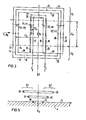
- FIG. 1 schematically shows the arrangement of a proposed RF surface coil.
- 2 shows a diagram of the course of lines of constant RF signal field strength resulting for this coil in a special sectional plane.
- FIGS. 3 and 4 show an RF surface coil for a device according to the invention and the signal field strength relationships resulting for this coil.
- FIG. 5 A further design option for surface coils according to the invention is indicated in FIG. 5.
- Fig. 1 shows a surface coil, as proposed with the German patent application P 33403376 (VPA 83 P 3384 DE).
- This coil generally designated 2
- This body part is introduced in a known manner into an at least partially homogeneous basic magnetic field B 0 of a corresponding magnet of a nuclear magnetic resonance apparatus (not shown in the figure).
- a right-angled xyz coordinate system is placed so that the z-axis points in the orientation direction of the basic magnetic field B Q.
- the xy plane and the yz plane are illustrated in more detail in the figure and denoted by E xy and E yz , respectively.
- E xy and E yz are illustrated in more detail in the figure and denoted by E xy and E yz , respectively.
- the surface coil 2 has a rectangular shape according to the selected embodiment. But it can also have a round, for example oval or circular shape. Because of the shape assumed in the figure, the coil 2 has two parallel longitudinal conductor pieces 7 and 8, between which transverse conductor pieces 9 and 10 run. The coil 2 is aligned with respect to the basic magnetic field B Q in such a way that its longitudinal conductor pieces 7 and 8 run at least approximately at right angles to this field. The transverse conductor pieces 9 and 10, which are substantially shorter than the longitudinal conductor pieces 7 and 8, are thus essentially parallel to this basic field. Because of this alignment of the longitudinal conductor pieces 7 and 8, it is advantageously achieved that approximately the same field characteristic is formed in the radiation of the RF signals in each yz cross-sectional plane. The same applies to the case of receipt. It can then be achieved that the received RF signals can be more clearly assigned to an area which is limited by the geometrical extent of the area between the longitudinal conductor pieces of the coil.
- the longitudinal conductor pieces 7 and 8 are advantageously at least three times longer than the transverse conductor pieces 9 and 10.
- the transverse conductor pieces 9 and 10 are also advantageously arranged so as to be lifted off the body surface 3, so that they are in Larger distance to the signal source in the body part 4 are compared to the two longitudinal conductor pieces 7 and 8.
- other measures such as. B. a high-frequency shielding of the transverse conductor pieces can be provided.
- the high-frequency alternating field of the surface coil 2 with the field strength B 1 is overlaid by the significantly stronger magnetic basic field B 0 , it follows that the components of the much weaker high-frequency alternating field, which correspond to the orientation direction of the basic field B 0 , are practically ineffective .
- z. B. in the transverse xy plane E xy a course of lines of constant effective signal strength, as can be seen from the diagram in FIG. 2.
- the relative signal strength ratios of the received RF signals to be determined are entered on the respective curves in this diagram with location coordinates in arbitrary units.
- the signal strength is determined after a 90 ° pulse as the product of B 1 and sin (const. B 1 ).
- the surface coil 2 according to FIG. 1 has the area of greatest signal strength and thus greatest sensitivity with relatively small y values, ie in the vicinity of the surface 3 of the body part 4 to be examined associated difficulties with regard to the examination of lower-lying parts of the body can be significantly reduced with the inventive design of the HF surface coil.
- An embodiment of such a coil can be seen in more detail in FIG. 3, parts corresponding to FIG. 1 are provided with the same reference numerals.
- the surface coil according to the invention according to FIG. 3 is designed in such a way that it has several turns, each of which consists either of only a single conductor piece or of conductor pieces combined in groups. These windings should be arranged so that they at least partially enclose each other and are also spaced apart.
- FIG. 3 of such a surface coil generally designated 12, it is assumed that it has a rectangular shape. However, it can also have a round, for example oval or circular shape.
- the coil 12 is elongated in the x-direction, ie its longitudinal conductor pieces 13 to 22 oriented at least approximately parallel to the x-axis are essential, preferably at least three times longer than their respectively assigned transverse conductor pieces 24 to 32.
- the transverse conductor pieces are from the surface of the body part either lifted according to Fig. 1 or arranged shielded, so that between two zones Z 1 and Z 2 with lifted or shielded conductor pieces, the surface coil 12 rests only with its longitudinal conductor pieces 13 to 22 in an active zone Z a on the body surface.
- the arrangement of the longitudinal conductor pieces 13 to 22 is understood directly on the body surface 3 and also at a short distance, for example a few centimeters above it.
- the active parts of the individual turns of the surface coil 12 are grouped together by directly adjacent or superimposed longitudinal lines formed with the same direction of current flow.
- the coil thus contains two groups G 1 and G1 from the longitudinal conductor pieces 16 and 17 or 18 and 19, which are each arranged symmetrically to the x-axis from the latter with an average distance d 1 .
- the number of longitudinal conductor pieces in these groups is denoted by n 1 .
- the longitudinal conductor pieces 16 to 19 virtually form an inner partial winding 35, indicated by a dotted line, which is enclosed by an outer partial winding.
- the active part of this outer partial winding is formed by two groups G 2 and G2, each with the longitudinal conductor pieces 13 to 15 and 20 to 22.
- the individual longitudinal conductor pieces 13 to 22 are connected via the transverse conductor pieces 24 to 32 in such a way that the directions of current flow indicated by arrows through the longitudinal conductor pieces of each individual group are the same, but adjacent groups have opposite directions of current flow.
- the extension L of the active zone Z a in the x direction is chosen to be considerably larger than the distance d 2 or d 1 . It can thus be ensured that practically only the y component of the high-frequency alternating field B 1 is effective.
- the active lengths of the individual groups in the direction of the x-axis can also have different sizes, ie the active length of the groups G 1 and G ' 1 can, for. B. be greater or less than the active length of the groups G 2 and G ' 2 .
- the distances d 1 and d 2 are chosen so that they are in relation to the number of conductors n 1 and n 2 stand, the field in the center of the arrangement is advantageous, ie practically completely extinguished in the coordinate origin and the zone of maximum sensitivity is shifted deeper into the interior of the body.
- the field strength runs in the area of this depth in the form of a saddle point, which in this case is approximately
- the curves of constant signal strength for a cut in the x-y plane are entered in accordance with the representation of the diagram according to FIG. 2.
- the sensitivity maximum is now not near the x-axis with relatively small y-values, but is shifted towards larger y-values. This shift is synonymous with the shift of the sensitivity maximum towards correspondingly larger body depths.
- each with two pairs of conductor groups G 1 -G ' 1 or G-G2 it is of course also possible to provide coils which also have further groups of longitudinal conductor pieces which are further away from the x-axis .
- the number n of longitudinal conductor pieces of these groups located further away does not necessarily have to increase continuously with increasing distance from the x-axis.
Abstract
Eine Einrichtung zur Erzeugung eines magnetischen Hochfrequenz-Feldes und/oder zum Empfangen von entsprechenden Hochfrequenz Signalen in einer Kernspinresonanz-Apparatur, insbesondere der medizinischen Technik, enthält eine Oberflächenspule, welche innerhalb eines zumindest teilweise homogenen Magnetfeldbereiches des von einem Grundfeldmagneten erzeugten, längs einer Achse orientierten Magnetfeldes zumindest in der Nähe eines zu untersuchenden Körpers oder Körperteils anzuordnen ist. Bei dieser Einrichtung soll die Empfindlichkeit der Oberflächenspule in Tiefenrichtung einstellbar sein. Die Erfindung sieht hierzu vor, daß die Oberflächenspule (12) mehrere Windungen aufweist, die sich zumindest teilweise umschließen und an verschiedenen geometrischen Orten anzuordnen sind. Dabei soll jede Windung zumindest weitgehend aus einem einzigen Leiterstück oder aus mehreren, jeweils zu einer Gruppe (G1, G'1, G2, G'2) zusammengefaßten Leiterstücken (13 bis 22) bestehen, wobei die Stromflußrichtungen in zueinander benachbarten Windungen jeweils entgegengesetzt sind.A device for generating a magnetic high-frequency field and / or for receiving corresponding high-frequency signals in a magnetic resonance apparatus, in particular medical technology, contains a surface coil which is oriented along an axis within an at least partially homogeneous magnetic field region of the one generated by a basic field magnet Magnetic field is to be arranged at least in the vicinity of a body or body part to be examined. With this device, the sensitivity of the surface coil should be adjustable in the depth direction. For this purpose, the invention provides that the surface coil (12) has a plurality of turns, which at least partially enclose each other and are to be arranged at different geometric locations. Each turn should consist at least largely of a single conductor piece or of several conductor pieces (13 to 22) each grouped into a group (G1, G'1, G2, G'2), the directions of current flow in mutually adjacent turns being opposite each other .
Description
Die Erfindung bezieht sich auf eine Einrichtung zur Erzeugung eines magnetischen Hochfrequenz-Feldes und/oder zum Empfangen von entsprechenden Hochfrequenz-Signalen in einer Kernspinresonanz-Apparatur, insbesondere der medizinischen Technik, mit einer Hochfrequenz-Oberflächenspule, welche innerhalb eines zumindest teilweise homogenen Magnetfeldbereiches des von einem Grundfeldmagneten erzeugten, längs einer Achse orientierten Magnetfeldes entweder unmittelbar auf einem zu untersuchenden Körper oder Körperteil oder zumindest in der Nähe desselben anzuordnen ist. Eine derartige Hochfrequenz-Einrichtung geht z. B. aus Berichten des "Second Annual Meeting of the Society of Magnetic Resonance in Medicine", Aug. 16.-19., 1983, San Francisco, USA (vgl. insbesondere Seiten 16 und 17, 53 und 54 oder 83 und 84) hervor.The invention relates to a device for generating a magnetic high-frequency field and / or for receiving corresponding high-frequency signals in a magnetic resonance apparatus, in particular medical technology, with a high-frequency surface coil, which within an at least partially homogeneous magnetic field range of A magnetic field generated along a basic axis is to be arranged either directly on a body or body part to be examined or at least in the vicinity thereof. Such a high-frequency device goes z. B. from reports of the "Second Annual Meeting of the Society of Magnetic Resonance in Medicine", Aug. 16-19, 1983, San Francisco, USA (see in
Insbesondere auf dem Gebiet der medizinischen Technik sind Diagnoseverfahren entwickelt worden, bei denen rechnerisch oder meßtechnisch integrale Resonanzsignale von Kernen eines bestimmten Elementes aus der Spindichteverteilung und/oder aus der Relaxationszeitenverteilung eines zu untersuchenden Körpers bzw. Körperteiles analysiert werden. Entsprechende Verfahren sind unter der Bezeichnung "Kernspintomographie" (Nuclear Magnetic Resonance Tomography) oder "Zeugmatographie" bekannt.Diagnostic methods have been developed in particular in the field of medical technology, in which resonance signals of nuclei of a certain element, which are integral in terms of calculation or measurement technology, are analyzed from the spin density distribution and / or from the relaxation time distribution of a body or body part to be examined. Corresponding methods are known under the name "nuclear magnetic resonance tomography" or "stuff matography".
Voraussetzung für die Kernspintomographie ist ein von einem sogenannten Grundfeldmagneten erzeugtes starkes Magnetfeld, das in einem Bereich vorbestimmter Ausdehnung möglichst homogen ist und in das der zu untersuchende Körper bzw. der Körperteil längs einer Achse, die im allgemeinen mit der Orientierungsachse des magnetischen Grundfeldes übereinstimmt, eingebracht wird. Zur Anregung der Atomkerne eines vorbestimmten Elementes in dem Körper zu einer Präzessionsbewegung ist außerdem eine besondere Spule erforderlich, mit der kurzzeitig ein hochfrequentes magnetisches Wechselfeld (HF-Wechselfeld) erzeugt werden und die auch zum Empfang der damit verbundenen HF-Signale dienen kann, falls keine besondere Meßspule vorgesehen wird. Gegebenenfalls kann das Grundfeld lokal auch variiert werden, um damit den Bereich, der durch das hochfrequente Signal der Oberflächenspule angeregt wird, zu beschränken (Topological NMR; Sensitive Point Method).A prerequisite for magnetic resonance imaging is a strong one generated by a so-called basic field magnet Magnetic field which is as homogeneous as possible in a region of predetermined extent and into which the body to be examined or the body part is introduced along an axis which generally coincides with the orientation axis of the basic magnetic field. To excite the atomic nuclei of a predetermined element in the body for a precession movement, a special coil is also required, with which a high-frequency alternating magnetic field (alternating RF field) is generated and which can also serve to receive the associated RF signals, if none special measuring coil is provided. If necessary, the basic field can also be varied locally in order to limit the area which is excited by the high-frequency signal of the surface coil (Topological NMR; Sensitive Point Method).
Für spezielle Apparaturen, mit denen beispielsweise die im menschlichen Körper im Vergleich zu den 1H-Kernen verhältnismäßig wenig auftretenden 31P-Kerne oder 13 C-Ker- ne angeregt bzw. deren Kernspinresonanz-Signale empfangen werden, sind HF-Spulen bekannt, die aus Gründen einer ausreichend großen Empfindlichkeit in oberflächennahen Körperbereichen angeordnet, d. h. insbesondere auf die Körperoberfläche aufgelegt werden. Als hierfür geeignete HF-Spulen, die deshalb auch als Oberflächenspulen bezeichnet werden, verwendet man im allgemeinen kreisringförmige Wicklungen mit einer einzigen oder mehreren Windungen (vgl. die eingangs genannten Berichte).For special apparatus with which, for example, in the human body as compared with the 1 H nuclei relatively little occurring 31 P nuclei, or 13 C - nuclei excited and their nuclear magnetic resonance signals are received, the RF coil are known which arranged for reasons of a sufficiently high sensitivity in areas of the body near the surface, ie in particular placed on the body surface. Suitable RF coils, which are therefore also referred to as surface coils, are generally circular windings with one or more turns (cf. the reports mentioned at the beginning).
Derartige Oberflächenspulen haben jedoch ihr Empfindlichkeitsmaximum in oberflächennahen Bereichen. Will man aber speziell tiefergelegene Körperteile mit diesen Spulen untersuchen, in denen deren Empfindlichkeit vergleichsweise geringer ist, so läßt sich nicht vermeiden, daß die zu gewinnenden Resonanzsignale stets von den verhältnismäßig starken Signalen aus den oberflächennahen Bereichen überlagert sind. Die Signalanalyse ist somit entsprechend erschwert, und vielfach ist eine eindeutige Aussage bezüglich der tiefergelegenen Körperteile ausgeschlossen.However, such surface coils have their maximum sensitivity in areas close to the surface. But if you want to examine lower parts of the body with these coils, in which their sensitivity is comparatively lower, you cannot ver avoid that the resonance signals to be obtained are always superimposed by the relatively strong signals from the areas near the surface. The signal analysis is therefore correspondingly difficult, and in many cases a clear statement regarding the lower parts of the body is excluded.
Aufgabe der vorliegenden Erfindung ist es deshalb, die eingangs genannte Hochfrequenz-Einrichtung dahingehend zu verbessern, daß die Empfindlichkeit ihrer Oberflächenspule in Tiefenrichtung so einstellbar ist, daß verhältnismäßig starke Resonanzsignale insbesondere von tiefergelegenen Teilen des zu untersuchenden Körpers zu gewinnen sind.The object of the present invention is therefore to improve the high-frequency device mentioned at the outset in such a way that the sensitivity of its surface coil in the depth direction can be adjusted such that relatively strong resonance signals can be obtained, in particular from lower-lying parts of the body to be examined.
Diese Aufgabe wird erfindungsgemäß dadurch gelöst, daß die Oberflächenspule mehrere Windungen aufweist, die zumindest teilweise sich umschließend an verschiedenen geometrischen Orten angeordnet sind, wobei jede Windung zumindest weitgehend aus einem einzigen Leiterstück oder aus mehreren, jeweils zu einer Gruppe zusammengefaßten Leiterstücken besteht und die Stromflußrichtungen in zueinander benachbarten Windungen jeweils entgegengesetzt sind.This object is achieved in that the surface coil has a plurality of turns, which are at least partially arranged at different geometric locations, each turn consisting at least largely of a single conductor piece or of several conductor pieces combined into a group and the current flow directions in mutually adjacent turns are each opposite.
Die mit dieser Ausgestaltung der Hochfrequenz-Einrichtung verbundenen Vorteile sind insbesondere darin zu sehen, daß mit einer geeigneten Wahl der Anzahl der Windungen, ihrer geometrischen Größe und Lage sowie der Anzahl ihrer Leiterstücke eine ausgeprägte Richtcharakteristik in Tiefenrichtung senkrecht zur Oberfläche des zu untersuchenden Körpers zu erhalten ist. D. h., es lassen sich damit charakteristische Zonen höherer und niedrigerer Empfindlichkeit bezüglich der Körpertiefe erreichen. Vorteilhafte Ausgestaltungen der erfindungsgemäßen Hochfrequenz-Einrichtung gehen aus den Unteransprüchen hervor.The advantages associated with this configuration of the high-frequency device are to be seen in particular in that, with a suitable choice of the number of turns, their geometric size and position, and the number of their conductor pieces, a pronounced directional characteristic in the depth direction perpendicular to the surface of the body to be examined can be obtained is. This means that characteristic zones of higher and lower sensitivity with regard to body depth can be achieved. Advantageous refinements of the high-frequency device according to the invention emerge from the subclaims.
Zur weiteren Erläuterung der Erfindung wird nachfolgend auf die Zeichnung Bezug genommen. Dabei zeigt Fig. 1 schematisch die Anordnung einer vorgeschlagenen HF-Oberflächenspule. In Fig. 2 ist in einem Diagramm der sich für diese Spule in einer speziellen Schnittebene ergebende Verlauf von Linien konstanter HF-Signalfeldstärke wiedergegeben. In entsprechender Darstellung gehen aus den Fig. 3 und 4 eine HF-Oberflächenspule für eine erfindungsgemäße Einrichtung bzw. die sich für diese Spule ergebenden Signalfeldstärkeverhältnisse hervor. In Fig. 5 ist eine weitere Ausgestaltungsmöglichkeit für erfindungsgemäße Oberflächenspulen angedeutet.To further explain the invention, reference is made below to the drawing. 1 schematically shows the arrangement of a proposed RF surface coil. 2 shows a diagram of the course of lines of constant RF signal field strength resulting for this coil in a special sectional plane. In a corresponding representation, FIGS. 3 and 4 show an RF surface coil for a device according to the invention and the signal field strength relationships resulting for this coil. A further design option for surface coils according to the invention is indicated in FIG. 5.
Fig. 1 zeigt eine Oberflächenspule, wie sie mit der deutschen Patentanmeldung P 33403376 (VPA 83 P 3384 DE) vorgeschlagen ist. Diese allgemein mit 2 bezeichnete Spule weist eine einzige Windung auf, deren Leiterteile symmetrisch zu einem Punkt 0 auf der Oberfläche 3 eines zu untersuchenden Körpers oder Körperteiles 4 zumindest teilweise aufgelegt sind. Dieser Körperteil ist in bekannter Weise in ein zumindest teilweise homogenes magnetisches Grundfeld B 0 eines entsprechenden Magneten einer in der Figur nicht dargestellten Kernspinresonanz-Apparatur eingebracht. Durch den Punkt 0 ist ein rechtwinkliges x-y-z-Koordinatensystem so gelegt, daß die z-Achse in die Orientierungsrichtung des magnetischen Grundfeldes BQ weist. Außerdem sind in der Figur die x-y-Ebene und die y-z-Ebene näher veranschaulicht und mit Exy bzw. Eyz bezeichnet. Mit Hilfe eines hochfrequenten Wechselstromes I durch die Oberflächenspule 2 wird dann ein für entsprechende Resonanzexperimente erforderliches kurzzeitiges HF-Feld der Feldstärke B1 erzeugt. Die Oberflächenspule kann hierbei auch als Empfänger für die nach dem Abschalten des HF-Feldes zu empfangenden HF-Signale aus dem Inneren des Körperteiles 4 dienen.Fig. 1 shows a surface coil, as proposed with the German patent application P 33403376 (VPA 83 P 3384 DE). This coil, generally designated 2, has a single turn, the conductor parts of which are at least partially placed symmetrically to a point 0 on the
Die Oberflächenspule 2 hat gemäß dem gewählten Ausführungsbeispiel eine rechteckförmige Gestalt. Sie kann aber auch runde, beispielsweise ovale oder kreisringförmige Gestalt haben. Auf Grund der in der Figur angenommenen Form weist die Spule 2 zwei parallele Längsleiterstücke 7 und 8 auf, zwischen denen Querleiterstücke 9 und 10 verlaufen. Die Spule 2 ist dabei so bezüglich des magnetischen Grundfeldes BQ ausgerichtet, daß ihre Längsleiterstücke 7 und 8 zumindest annähernd rechtwinklig zu diesem Feld verlaufen. Die gegenüber den Längsleiterstükken 7 und 8 wesentlich kürzeren Querleiterstücke 9 und 10 liegen somit im wesentlichen parallel zu diesem Grundfeld. Auf Grund dieser Ausrichtung der Längsleiterstücke 7 und 8 wird nämlich vorteilhaft erreicht, daß in jeder y-z-Querschnittsebene annähernd die gleiche Feldcharakteristik bei der Abstrahlung der HF-Signale ausgebildet wird. Entsprechendes gilt auch für den Empfangsfall. Es läßt sich dann erreichen, daß die empfangenen HF-Signale eindeutiger einem Bereich zuzuordnen sind, der durch die geometrische Ausdehnung der Fläche zwischen den Längsleiterstücken der Spule begrenzt wird.The
Vorteilhaft sind die Längsleiterstücke 7 und 8 mindestens dreimal länger als die Querleiterstücke 9 und 10. Um Endeffekte der Spule 2 zu reduzieren, sind außerdem vorteilhaft die Querleiterstücke 9 und 10 von der Körperoberfläche 3 abgehoben angeordnet, so daß sie sich in größerer Entfernung zu der Signalquelle in dem Körperteil 4 befinden als vergleichsweise die beiden Längsleiterstücke 7 und 8. Neben dieser in der Figur dargestellten Maßnahme zur Reduzierung von Endeffekten können auch andere Maßnahmen wie z. B. eine hochfrequenzmäßige Abschirmung der Querleiterstücke vorgesehen werden.The
Da das hochfrequente Wechselfeld der Oberflächenspule 2 mit der Feldstärke B1 von dem ganz wesentlich stärkeren magnetischen Grundfeld B0 überlagert wird, folgt daraus, daß die Komponenten des sehr viel schwächeren hochfrequenten Wechselfeldes, welche mit der Orientierungsrichtung des Grundfeldes B0 übereinstimmen, praktisch unwirksam sind. Für die mit der Oberflächenspule 2 zu empfangenden HF-Signale ergibt sich dann z. B. in der transversalen x-y-Ebene E xy ein Verlauf von Linien konstanter wirksamer Signalstärke, wie er aus dem Diagramm der Fig. 2 hervorgeht. In diesem Diagramm mit Ortskoordinaten in willkürlichen Einheiten sind die zu ermittelnden relativen Signalstärkeverhältnisse der empfangenen HF-Signale an den jeweiligen Kurven eingetragen. Die Signalstärke wird dabei nach einem 90°-Impuls als Produkt aus B1 und sin (const. B1) ermittelt.Since the high-frequency alternating field of the
Wie aus dem Diagramm der Fig. 2 ohne weiteres ersichtlich ist, liegt bei der Oberflächenspule 2 gemäß Fig. 1 der Bereich größter Signalstärke und damit größter Empfindlichkeit bei verhältnismäßig kleinen y-Werten, d. h. in Nähe der Oberfläche 3 des zu untersuchenden Körperteiles 4. Die damit verbundenen Schwierigkeiten hinsichtlich der Untersuchung von tiefergelegenen Körperteilen lassen sich mit der erfindungsgemäßen Ausgestaltung der HF-Oberflächenspule wesentlich verringern. Ein Ausführungsbeispiel einer derartigen Spule geht aus Fig. 3 näher hervor, wobei mit Fig. 1 übereinstimmende Teile mit den gleichen Bezugszeichen versehen sind.As can easily be seen from the diagram in FIG. 2, the
Zur Verbesserung der Richtcharakteristik bezüglich der Körpertiefe ist die erfindungsgemäße Oberflächenspule nach Fig. 3 dahingehend ausgestaltet, daß sie mehrere Windungen aufweist, die jeweils entweder nur aus einem einzigen Leiterstück oder aus gruppenweise zusammengefaßten Leiterstücken bestehen. Diese Windungen sollen so zueinander angeordnet sein, daß sie sich zumindest teilweise umschließen und außerdem untereinander beabstandet sind. Bei dem in Fig. 3 gezeigten Ausführungsbeispiel einer derartigen, allgemein mit 12 bezeichneten Oberflächenspule ist davon ausgegangen, daß sie rechteckige Form hat. Ebenso kann sie jedoch auch eine runde, beispielsweise ovale oder kreisringförmige Gestalt haben. Die Spule 12 ist in x-Richtung langgestreckt ausgeführt, d. h. ihre zumindest annähernd parallel zur x-Achse ausgerichteten Längsleiterstücke 13 bis 22 sind wesentlich, vorzugsweise mindestens dreimal länger als ihre jeweils zugeordneten Querleiterstücke 24 bis 32. Außerdem sind die Querleiterstücke von der Oberfläche des Körperteiles entweder entsprechend Fig. 1 abgehoben oder aber abgeschirmt angeordnet, so daß zwischen zwei Zonen Z1 und Z2 mit abgehobenen oder abgeschirmten Leiterstücken die Oberflächenspule 12 nur mit ihren Längsleiterstücken 13 bis 22 in einer aktiven Zone Z a auf der Körperoberfläche aufliegt. Hierbei wird definitionsgemäß sowohl die Anordnung der Längsleiterstücke 13 bis 22 unmittelbar auf der Körperoberfläche 3 als auch in geringer Entfernung von beispielsweise einigen Zentimetern über derselben verstanden.In order to improve the directional characteristic with regard to the body depth, the surface coil according to the invention according to FIG. 3 is designed in such a way that it has several turns, each of which consists either of only a single conductor piece or of conductor pieces combined in groups. These windings should be arranged so that they at least partially enclose each other and are also spaced apart. In the exemplary embodiment shown in FIG. 3 of such a surface coil, generally designated 12, it is assumed that it has a rectangular shape. However, it can also have a round, for example oval or circular shape. The
Die aktiven Teile der einzelnen Windungen der Oberflächenspule 12 werden von zu Gruppen zusammengefaßten, unmittelbar neben- oder aufeinanderliegenden Längsleiterstücken mit gleicher Stromflußrichtung gebildet. So enthält die Spule zwei Gruppen G1 und G1 aus den Längsleiterstücken 16 und 17 bzw. 18 und 19, die jeweils symmetrisch zur x-Achse von dieser mit einem mittleren Abstand d1 entfernt angeordnet sind. Die Anzahl von Längsleiterstücken in diesen Gruppen ist mit n1 bezeichnet. Die Längsleiterstücke 16 bis 19 bilden quasi eine durch eine punktierte Linie angedeutete innere Teilwicklung 35, welche von einer äußeren Teilwicklung umschlossen ist. Der aktive Teil dieser äußeren Teilwicklung wird von zwei Gruppen G2 und G2 mit jeweils den Längsleiterstücken 13 bis 15 bzw. 20 bis 22 gebildet. Die mittlere Entfernung dieser somit n2 = 3 Längsleiterstücke enthaltenden Gruppen von der x-Achse ist mit d2 bezeichnet. Die einzelnen Längsleiterstücke 13 bis 22 sind dabei über die Querleiterstücke 24 bis 32 so verbunden, daß die durch Pfeile angedeuteten Stromflußrichtungen durch die Längsleiterstücke jeder einzelnen Gruppe gleich sind, jedoch untereinander benachbarte Gruppen entgegengesetzte Stromflußrichtungen aufweisen.The active parts of the individual turns of the
Wesentlich für die Oberflächenspule 12 nach Fig. 3 ist auch, daß die Ausdehnung L der aktiven Zone Za in x-Richtung erheblich größer gewählt wird als der Abstand d2 bzw. d1. Es läßt sich so gewährleisten, daß praktisch nur die y-Komponente des hochfrequenten Wechselfeldes B1 wirksam ist. Darüber hinaus können gegebenenfalls die aktiven Längen der einzelnen Gruppen in Richtung der x-Achse auch unterschiedliche Größen haben, d. h., die aktive Länge der Gruppen G1 und G' 1 kann z. B. größer oder kleiner als die aktive Länge der Gruppen G2 und G' 2 sein. Werden ferner die Abstände d1 und d2 so gewählt, daß sie mit den Leiterzahlen n1 und n2 im Verhältnis

liegt. Auf diese Weise können beispielsweise auf dem Gebiet der medizinischen Technik eindeutigere Aussagen über tiefergelegene Körperteile wie beispielsweise innere Organe erhalten werden.lies. In this way, for example in the field of medical technology, clearer statements can be obtained about lower parts of the body, such as internal organs.
Ein entsprechendes Ausführungsbeispiel einer erfindungsgemäßen Oberflächenspule mit jeweils n=2 Längsleiterstücken pro Gruppe ist dem Diagramm der Fig. 4 zugrundegelegt. In diesem Diagramm sind entsprechend der Darstellung des Diagrammes nach Fig. 2 die Kurven konstanter Signalstärke bei einem Schnitt in der x-y-Ebene eingetragen. Wie aus dem Diagramm insbesondere durch einen Vergleich mit dem Diagramm der Fig. 2 ersichtlich ist, liegt das Empfindlichkeitsmaximum nunmehr nicht nahe der x-Achse bei verhältnismäßig kleinen y-Werten, sondern es ist nach größeren y-Werten hin verschoben. Diese Verschiebung ist gleichbedeutend mit der Verschiebung des Empfindlichkeitsmaximums zu entsprechend größeren Körpertiefen hin.The diagram of FIG. 4 is based on a corresponding exemplary embodiment of a surface coil according to the invention, each with n = 2 longitudinal conductor pieces per group. In this diagram, the curves of constant signal strength for a cut in the x-y plane are entered in accordance with the representation of the diagram according to FIG. 2. As can be seen from the diagram, in particular by a comparison with the diagram of FIG. 2, the sensitivity maximum is now not near the x-axis with relatively small y-values, but is shifted towards larger y-values. This shift is synonymous with the shift of the sensitivity maximum towards correspondingly larger body depths.
Bei dem Ausführungsbeispiel einer Oberflächenspule nach Fig. 3 wurde davon ausgegangen, daß sich die Längsleiterstücke ihrer einzelnen Leitergruppen alle in der x-z-Ebene auf der Oberfläche 3 des zu untersuchenden Körperteiles 4 befinden sollen. Eine derartige Anordnung ist jedoch nicht unbedingt erforderlich. Wie nämlich aus dem in Fig. 5 schematisch dargestellten Schnitt in einer y-z-Ebene hervorgeht, können auch die zu den jeweiligen Gruppen gehörenden Längsleiterstücke in unterschiedlichen Ebenen liegen. In der Figur ist ein Gruppenpaar G3-G3 mit jeweils drei Längsleiterstücken 36 bis 38 bzw. 39 bis 41 angenommen, wobei nur die Längsleiterstücke 38 und 41 unmittelbar auf der Oberfläche 3 des Körperteiles 4 oder in geringem Abstand von derselben zu liegen kommen.3, it was assumed that the longitudinal conductor pieces of their individual conductor groups should all be in the xz plane on the
Neben der Ausbildung der Oberflächenspule 12 nach Fig. 3 mit jeweils zwei Paaren von Leitergruppen G1-G' 1 bzw. G-G2 können selbstverständlich auch Spulen vorgesehen werden, die noch weitere, von der x-Achse weiter entfernt liegenden Gruppen von Längsleiterstücken aufweisen. Dabei muß die Anzahl n der Längsleiterstücke dieser weiter entfernt liegenden Gruppen nicht unbedingt mit zunehmendem Abstand von der x-Achse kontinuierlich zunehmen. Im allgemeinen ist es jedoch zweckmäßig, daß zumindest für die beiden der x- Achse am nächsten liegenden Gruppen G1 und G2 bzw. G' 1 und G2 die Anzahl ihrer Längsleiterstücke zunimmt, d. h. daß gilt: n2>n1.In addition to the formation of the
Neben der in Fig. 3 angedeuteten besonderen Hintereinanderschaltung der einzelnen Längsleiterstücke ist prinzipiell auch eine Parallelschaltung von Einzelspulen denkbar. Hierbei ist jedoch zu beachten, daß bei einer inhomogenen Struktur des zu untersuchenden Körperteiles auch eine unsymmetrische Aufteilung des Stromes auf die einzelnen Spulen auftreten kann.In addition to the special series connection of the individual longitudinal conductor pieces indicated in FIG. 3, in principle a parallel connection of individual coils is also conceivable. It should be noted here, however, that with an inhomogeneous structure of the body part to be examined, an asymmetrical distribution of the current between the individual coils can also occur.
Claims (11)

Applications Claiming Priority (2)
| Application Number | Priority Date | Filing Date | Title |
|---|---|---|---|
| DE19833340384 DE3340384A1 (en) | 1983-11-08 | 1983-11-08 | HIGH-FREQUENCY DEVICE OF A NUCLEAR RESONANCE APPARATUS WITH A SURFACE COIL |
| DE3340384 | 1983-11-08 |
Publications (2)
| Publication Number | Publication Date |
|---|---|
| EP0142077A1 true EP0142077A1 (en) | 1985-05-22 |
| EP0142077B1 EP0142077B1 (en) | 1989-01-04 |
Family
ID=6213765
Family Applications (1)
| Application Number | Title | Priority Date | Filing Date |
|---|---|---|---|
| EP84112771A Expired EP0142077B1 (en) | 1983-11-08 | 1984-10-23 | High-frequency device in a nuclear-spin resonance apparatus with a surface coil |
Country Status (4)
| Country | Link |
|---|---|
| US (1) | US4592363A (en) |
| EP (1) | EP0142077B1 (en) |
| JP (1) | JPS60117138A (en) |
| DE (2) | DE3340384A1 (en) |
Cited By (10)
| Publication number | Priority date | Publication date | Assignee | Title |
|---|---|---|---|---|
| EP0171741A2 (en) * | 1984-08-16 | 1986-02-19 | General Electric Company | NMR Spectroscopy body probes with at least one surface coil |
| WO1987001199A1 (en) * | 1985-08-14 | 1987-02-26 | Picker International Inc. | Surface coil system for magnetic resonance imaging |
| EP0212716A2 (en) * | 1985-08-08 | 1987-03-04 | North American Philips Corporation | Flexible surface coil for magnetic resonance imaging |
| EP0218290A1 (en) * | 1985-09-25 | 1987-04-15 | Koninklijke Philips Electronics N.V. | A magnetic resonance apparatus with a decoupling detection surface coil |
| FR2592715A1 (en) * | 1986-01-07 | 1987-07-10 | Thomson Cgr | ORBIT ANTENNA FOR NUCLEAR MAGNETIC RESONANCE IMAGING APPARATUS |
| EP0273484A2 (en) * | 1986-11-27 | 1988-07-06 | Koninklijke Philips Electronics N.V. | Magnetic resonance imaging apparatus comprising a stacked surface coil system |
| EP0290315A1 (en) * | 1987-05-07 | 1988-11-09 | General Electric Cgr S.A. | Receiving antenna using passive decoupling, particularly for use with a nuclear magnetic resonance imaging apparatus |
| EP0338624A1 (en) * | 1988-04-20 | 1989-10-25 | Koninklijke Philips Electronics N.V. | Magnetic resonance apparatus with uncoupled rf coils |
| EP0364061A2 (en) * | 1988-10-14 | 1990-04-18 | The Regents Of The University Of California | Widened and shaped MRI surface coil having increased signal-to-noise ratio |
| EP0461723A2 (en) * | 1990-06-15 | 1991-12-18 | Philips Patentverwaltung GmbH | Surface coil for NMR examinations |
Families Citing this family (12)
| Publication number | Priority date | Publication date | Assignee | Title |
|---|---|---|---|---|
| JPS60139256U (en) * | 1984-02-28 | 1985-09-14 | 日本電子株式会社 | Coil for nuclear magnetic resonance measurement |
| EP0316440B1 (en) | 1985-03-19 | 1996-01-03 | Randell L. Mills | System and method for providing localized Mössbauer absorption in an organic medium |
| US4724389A (en) * | 1985-05-08 | 1988-02-09 | Medical College Of Wisconsin, Inc. | Loop-gap resonator for localized NMR imaging |
| US4920318A (en) * | 1985-08-14 | 1990-04-24 | Picker International, Inc. | Surface coil system for magnetic resonance imaging |
| US4752738A (en) * | 1985-08-14 | 1988-06-21 | Picker International, Inc. | Three dimensional localized coil for magnetic resonance imaging |
| US4718431A (en) * | 1985-10-22 | 1988-01-12 | Siemens Aktiengesellschaft | Surface coil with calibration substance for use in a nuclear magnetic resonance apparatus |
| GB8814187D0 (en) * | 1988-06-15 | 1988-07-20 | Mansfield P | Improvements in/relating to surface electrical coil structures |
| US5412322A (en) * | 1993-06-24 | 1995-05-02 | Wollin Ventures, Inc. | Apparatus and method for spatially ordered phase encoding and for determining complex permittivity in magnetic resonance by using superimposed time-varying electric fields |
| US6249121B1 (en) * | 1999-05-17 | 2001-06-19 | General Electric Company | RF body coil |
| JP2003511172A (en) * | 1999-10-11 | 2003-03-25 | コーニンクレッカ フィリップス エレクトロニクス エヌ ヴィ | MRI-RF coil with overlapping areas of sensitivity |
| US6297636B1 (en) * | 2000-01-11 | 2001-10-02 | Ge Yokogawa Medical Systems, Limited | RF coil, RF magnetic field generating apparatus and magnetic resonance imaging method and apparatus |
| JP3619485B2 (en) | 2001-10-24 | 2005-02-09 | ジーイー・メディカル・システムズ・グローバル・テクノロジー・カンパニー・エルエルシー | RF coil and magnetic resonance imaging apparatus |
Citations (6)
| Publication number | Priority date | Publication date | Assignee | Title |
|---|---|---|---|---|
| US4240439A (en) * | 1975-04-30 | 1980-12-23 | Hokkaido University | Method of obtaining information of a specified or target area of a living body near its skin surface by the application of a nuclear magnetic resonance phenomenon |
| GB2056086A (en) * | 1979-08-10 | 1981-03-11 | Emi Ltd | Improvements in or relating to imaging systems |
| GB2082775A (en) * | 1980-08-06 | 1982-03-10 | Emi Ltd | Nmr imaging apparatus and method |
| GB2094482A (en) * | 1981-02-02 | 1982-09-15 | Varian Associates | Saddle coil for nmr spectrometer |
| EP0071896A1 (en) * | 1981-08-12 | 1983-02-16 | Siemens Aktiengesellschaft | High frequency coil system for a nuclear resonance imaging apparatus |
| US4411270A (en) * | 1978-11-20 | 1983-10-25 | Damadian Raymond V | Apparatus and method for nuclear magnetic resonance scanning and mapping |
Family Cites Families (11)
| Publication number | Priority date | Publication date | Assignee | Title |
|---|---|---|---|---|
| US3234454A (en) * | 1962-09-04 | 1966-02-08 | Phillips Petroleum Co | Nuclear magnetic resonance well logging |
| US3388322A (en) * | 1966-02-21 | 1968-06-11 | Varian Associates | Gyromagnetic resonance spectrometer having selectable internal and external resonantcontrol groups |
| HU166127B (en) * | 1973-01-29 | 1975-01-28 | ||
| US3953789A (en) * | 1974-11-20 | 1976-04-27 | International Business Machines Corporation | Method of polarizing nuclei |
| DE2755357A1 (en) * | 1977-12-12 | 1979-06-13 | Euratom | COIL FOR GENERATING MAGNETIC FIELDS HIGH AND EXTREMELY HIGH HOMOGENITY |
| US4175251A (en) * | 1978-04-20 | 1979-11-20 | Schlumberger Technology Corporation | Nuclear magnetism logging method and system |
| US4439733A (en) * | 1980-08-29 | 1984-03-27 | Technicare Corporation | Distributed phase RF coil |
| JPS5848839A (en) * | 1981-09-18 | 1983-03-22 | Hitachi Ltd | Testing device using nuclear magnetic resonance |
| US4443760A (en) * | 1982-07-01 | 1984-04-17 | General Electric Company | Use of phase alternated RF pulses to eliminate effects of spurious free induction decay caused by imperfect 180 degree RF pulses in NMR imaging |
| US4517516A (en) * | 1983-04-08 | 1985-05-14 | Varian Associates, Inc. | NMR Probe coil form structure |
| DE3340337A1 (en) * | 1983-11-08 | 1985-05-15 | Siemens AG, 1000 Berlin und 8000 München | HIGH-FREQUENCY DEVICE OF A NUCLEAR RESONANCE APPARATUS |
-
1983
- 1983-11-08 DE DE19833340384 patent/DE3340384A1/en not_active Withdrawn
-
1984
- 1984-10-23 DE DE8484112771T patent/DE3475958D1/en not_active Expired
- 1984-10-23 EP EP84112771A patent/EP0142077B1/en not_active Expired
- 1984-10-26 US US06/665,175 patent/US4592363A/en not_active Expired - Fee Related
- 1984-11-07 JP JP59234848A patent/JPS60117138A/en active Pending
Patent Citations (6)
| Publication number | Priority date | Publication date | Assignee | Title |
|---|---|---|---|---|
| US4240439A (en) * | 1975-04-30 | 1980-12-23 | Hokkaido University | Method of obtaining information of a specified or target area of a living body near its skin surface by the application of a nuclear magnetic resonance phenomenon |
| US4411270A (en) * | 1978-11-20 | 1983-10-25 | Damadian Raymond V | Apparatus and method for nuclear magnetic resonance scanning and mapping |
| GB2056086A (en) * | 1979-08-10 | 1981-03-11 | Emi Ltd | Improvements in or relating to imaging systems |
| GB2082775A (en) * | 1980-08-06 | 1982-03-10 | Emi Ltd | Nmr imaging apparatus and method |
| GB2094482A (en) * | 1981-02-02 | 1982-09-15 | Varian Associates | Saddle coil for nmr spectrometer |
| EP0071896A1 (en) * | 1981-08-12 | 1983-02-16 | Siemens Aktiengesellschaft | High frequency coil system for a nuclear resonance imaging apparatus |
Cited By (19)
| Publication number | Priority date | Publication date | Assignee | Title |
|---|---|---|---|---|
| EP0171741A3 (en) * | 1984-08-16 | 1988-08-24 | General Electric Company | Nmr spectroscopy body probes with at least one surface coil |
| EP0171741A2 (en) * | 1984-08-16 | 1986-02-19 | General Electric Company | NMR Spectroscopy body probes with at least one surface coil |
| EP0212716A2 (en) * | 1985-08-08 | 1987-03-04 | North American Philips Corporation | Flexible surface coil for magnetic resonance imaging |
| EP0212716A3 (en) * | 1985-08-08 | 1988-06-29 | North American Philips Corporation | Flexible surface coil for magnetic resonance imaging |
| WO1987001199A1 (en) * | 1985-08-14 | 1987-02-26 | Picker International Inc. | Surface coil system for magnetic resonance imaging |
| EP0218290A1 (en) * | 1985-09-25 | 1987-04-15 | Koninklijke Philips Electronics N.V. | A magnetic resonance apparatus with a decoupling detection surface coil |
| FR2592715A1 (en) * | 1986-01-07 | 1987-07-10 | Thomson Cgr | ORBIT ANTENNA FOR NUCLEAR MAGNETIC RESONANCE IMAGING APPARATUS |
| EP0232189A1 (en) * | 1986-01-07 | 1987-08-12 | General Electric Cgr S.A. | Orbit coil for a nuclear magnetic resonance imaging apparatus |
| US4739269A (en) * | 1986-01-07 | 1988-04-19 | Thomson-Cgr | Orbit antenna for a nuclear magnetic resonance (NMR) imaging apparatus |
| EP0273484A2 (en) * | 1986-11-27 | 1988-07-06 | Koninklijke Philips Electronics N.V. | Magnetic resonance imaging apparatus comprising a stacked surface coil system |
| EP0273484A3 (en) * | 1986-11-27 | 1988-07-20 | N.V. Philips' Gloeilampenfabrieken | Magnetic resonance imaging apparatus comprising a stacked surface coil system |
| EP0290315A1 (en) * | 1987-05-07 | 1988-11-09 | General Electric Cgr S.A. | Receiving antenna using passive decoupling, particularly for use with a nuclear magnetic resonance imaging apparatus |
| FR2615040A1 (en) * | 1987-05-07 | 1988-11-10 | Thomson Cgr | PASSIVE DECOUPLING RECEIVING ANTENNA, IN PARTICULAR FOR NUCLEAR MAGNETIC RESISTANCE IMAGING APPARATUS |
| US4857850A (en) * | 1987-05-07 | 1989-08-15 | General Electric Cgr Sa. | Passive-decoupling receiving antenna, in particular for a nuclear magnetic resonance imaging apparatus |
| EP0338624A1 (en) * | 1988-04-20 | 1989-10-25 | Koninklijke Philips Electronics N.V. | Magnetic resonance apparatus with uncoupled rf coils |
| EP0364061A2 (en) * | 1988-10-14 | 1990-04-18 | The Regents Of The University Of California | Widened and shaped MRI surface coil having increased signal-to-noise ratio |
| EP0364061B1 (en) * | 1988-10-14 | 1995-03-08 | The Regents Of The University Of California | Widened and shaped MRI surface coil having increased signal-to-noise ratio |
| EP0461723A2 (en) * | 1990-06-15 | 1991-12-18 | Philips Patentverwaltung GmbH | Surface coil for NMR examinations |
| EP0461723A3 (en) * | 1990-06-15 | 1992-07-22 | Philips Patentverwaltung Gmbh | Surface coil for nmr examinations |
Also Published As
| Publication number | Publication date |
|---|---|
| US4592363A (en) | 1986-06-03 |
| EP0142077B1 (en) | 1989-01-04 |
| JPS60117138A (en) | 1985-06-24 |
| DE3475958D1 (en) | 1989-02-09 |
| DE3340384A1 (en) | 1985-05-15 |
Similar Documents
| Publication | Publication Date | Title |
|---|---|---|
| EP0142077B1 (en) | High-frequency device in a nuclear-spin resonance apparatus with a surface coil | |
| EP0073375B1 (en) | High-frequency device in a nuclear spin resonance apparatus | |
| DE69736826T2 (en) | Radio frequency coils for nuclear resonance | |
| EP0803736B1 (en) | MR apparatus with cylindrical coil means and with surface coil means | |
| DE4029477C2 (en) | Tesserale gradient coil for nuclear spin tomography devices | |
| DE3500456C2 (en) | Coil arrangement for an NMR examination device | |
| EP0586983B1 (en) | Gradient coil system for a therapy tomograph | |
| EP0200078B1 (en) | Apparatus for nuclear tomography | |
| EP1279968A2 (en) | Transceiver coil for MR apparatus | |
| DE3411521A1 (en) | NUCLEAR MAGNETIC RESONANCE DEVICE | |
| EP0361190A1 (en) | Surface coil arrangement for examinations with the aid of nuclear magnetic resonance | |
| DE3517812C2 (en) | ||
| DE3635006A1 (en) | PROBE FOR A MAGNETIC RESONANCE IMAGING DEVICE | |
| EP0197589A2 (en) | Coil arrangement for nuclear-spin inspections | |
| DE4024582A1 (en) | MRI | |
| EP0156979B1 (en) | High-frequency antenna arrangement in a nuclear magnetic resonance tomography apparatus and method for its operation | |
| EP0142079B1 (en) | High-frequency device in a nuclear-spin resonance apparatus | |
| DE60320376T2 (en) | COIL SYSTEM FOR AN MR DEVICE AND MR SYSTEM EQUIPPED WITH SUCH A REEL SYSTEM | |
| EP0401917B1 (en) | High-frequency quadrature coil system | |
| EP0432241B1 (en) | Probe head for whole-body nuclear-resonance tomography or local in vivo nuclear-resonance spectroscopy | |
| DE4138690A1 (en) | CIRCULAR POLARIZING LOCAL ANTENNA FOR A NUCLEAR SPIN RESONANCE DEVICE | |
| EP0157924B1 (en) | High-frequency antenna arrangement in a nuclear magnetic resonance tomography apparatus and method for its operation | |
| DE19535257A1 (en) | MR arrangement for determining the nuclear magnetization distribution with a surface coil arrangement | |
| EP0394508A1 (en) | Surface coil for a nuclear spin resonance apparatus | |
| DE69632349T2 (en) | RF coil arrangement for magnetic resonance |
Legal Events
| Date | Code | Title | Description |
|---|---|---|---|
| PUAI | Public reference made under article 153(3) epc to a published international application that has entered the european phase |
Free format text: ORIGINAL CODE: 0009012 |
|
| AK | Designated contracting states |
Designated state(s): DE FR GB NL |
|
| 17P | Request for examination filed |
Effective date: 19850705 |
|
| 17Q | First examination report despatched |
Effective date: 19861215 |
|
| R17C | First examination report despatched (corrected) |
Effective date: 19870514 |
|
| GRAA | (expected) grant |
Free format text: ORIGINAL CODE: 0009210 |
|
| AK | Designated contracting states |
Kind code of ref document: B1 Designated state(s): DE FR GB NL |
|
| PG25 | Lapsed in a contracting state [announced via postgrant information from national office to epo] |
Ref country code: NL Effective date: 19890104 |
|
| REF | Corresponds to: |
Ref document number: 3475958 Country of ref document: DE Date of ref document: 19890209 |
|
| ET | Fr: translation filed | ||
| GBT | Gb: translation of ep patent filed (gb section 77(6)(a)/1977) | ||
| NLV1 | Nl: lapsed or annulled due to failure to fulfill the requirements of art. 29p and 29m of the patents act | ||
| PGFP | Annual fee paid to national office [announced via postgrant information from national office to epo] |
Ref country code: FR Payment date: 19891026 Year of fee payment: 6 |
|
| PLBE | No opposition filed within time limit |
Free format text: ORIGINAL CODE: 0009261 |
|
| STAA | Information on the status of an ep patent application or granted ep patent |
Free format text: STATUS: NO OPPOSITION FILED WITHIN TIME LIMIT |
|
| 26N | No opposition filed | ||
| PGFP | Annual fee paid to national office [announced via postgrant information from national office to epo] |
Ref country code: GB Payment date: 19900913 Year of fee payment: 7 |
|
| PGFP | Annual fee paid to national office [announced via postgrant information from national office to epo] |
Ref country code: DE Payment date: 19901221 Year of fee payment: 7 |
|
| PG25 | Lapsed in a contracting state [announced via postgrant information from national office to epo] |
Ref country code: FR Effective date: 19910628 |
|
| REG | Reference to a national code |
Ref country code: FR Ref legal event code: ST |
|
| PG25 | Lapsed in a contracting state [announced via postgrant information from national office to epo] |
Ref country code: GB Effective date: 19911023 |
|
| GBPC | Gb: european patent ceased through non-payment of renewal fee | ||
| PG25 | Lapsed in a contracting state [announced via postgrant information from national office to epo] |
Ref country code: DE Effective date: 19920701 |