EP0145384A2 - Measuring conduit for flow rate and concentration of fluid - Google Patents
Measuring conduit for flow rate and concentration of fluid Download PDFInfo
- Publication number
- EP0145384A2 EP0145384A2 EP84308135A EP84308135A EP0145384A2 EP 0145384 A2 EP0145384 A2 EP 0145384A2 EP 84308135 A EP84308135 A EP 84308135A EP 84308135 A EP84308135 A EP 84308135A EP 0145384 A2 EP0145384 A2 EP 0145384A2
- Authority
- EP
- European Patent Office
- Prior art keywords
- measuring
- conduit
- fluid
- light transmitting
- concentration
- Prior art date
- Legal status (The legal status is an assumption and is not a legal conclusion. Google has not performed a legal analysis and makes no representation as to the accuracy of the status listed.)
- Granted
Links
- 239000012530 fluid Substances 0.000 title claims abstract description 39
- 230000003287 optical effect Effects 0.000 claims abstract description 4
- 230000000149 penetrating effect Effects 0.000 claims abstract 2
- CURLTUGMZLYLDI-UHFFFAOYSA-N Carbon dioxide Chemical compound O=C=O CURLTUGMZLYLDI-UHFFFAOYSA-N 0.000 abstract description 26
- 229910002092 carbon dioxide Inorganic materials 0.000 abstract description 16
- 239000001569 carbon dioxide Substances 0.000 abstract description 13
- 230000000241 respiratory effect Effects 0.000 abstract description 11
- 239000007789 gas Substances 0.000 description 19
- 238000005259 measurement Methods 0.000 description 19
- 238000000034 method Methods 0.000 description 7
- 230000029058 respiratory gaseous exchange Effects 0.000 description 4
- 238000012937 correction Methods 0.000 description 3
- 238000012545 processing Methods 0.000 description 3
- 230000008878 coupling Effects 0.000 description 2
- 238000010168 coupling process Methods 0.000 description 2
- 238000005859 coupling reaction Methods 0.000 description 2
- 238000010586 diagram Methods 0.000 description 2
- 239000007788 liquid Substances 0.000 description 2
- 230000001902 propagating effect Effects 0.000 description 2
- 230000001360 synchronised effect Effects 0.000 description 2
- 230000002411 adverse Effects 0.000 description 1
- QVGXLLKOCUKJST-UHFFFAOYSA-N atomic oxygen Chemical compound [O] QVGXLLKOCUKJST-UHFFFAOYSA-N 0.000 description 1
- 230000004323 axial length Effects 0.000 description 1
- 230000005540 biological transmission Effects 0.000 description 1
- 230000000694 effects Effects 0.000 description 1
- 238000011156 evaluation Methods 0.000 description 1
- 210000000056 organ Anatomy 0.000 description 1
- 229910052760 oxygen Inorganic materials 0.000 description 1
- 239000001301 oxygen Substances 0.000 description 1
- 229920002492 poly(sulfone) Polymers 0.000 description 1
- 239000011347 resin Substances 0.000 description 1
- 229920005989 resin Polymers 0.000 description 1
- 229910052594 sapphire Inorganic materials 0.000 description 1
- 239000010980 sapphire Substances 0.000 description 1
- 238000007493 shaping process Methods 0.000 description 1
- 239000000126 substance Substances 0.000 description 1
Images

Classifications
-
- G—PHYSICS
- G01—MEASURING; TESTING
- G01F—MEASURING VOLUME, VOLUME FLOW, MASS FLOW OR LIQUID LEVEL; METERING BY VOLUME
- G01F1/00—Measuring the volume flow or mass flow of fluid or fluent solid material wherein the fluid passes through a meter in a continuous flow
- G01F1/66—Measuring the volume flow or mass flow of fluid or fluent solid material wherein the fluid passes through a meter in a continuous flow by measuring frequency, phase shift or propagation time of electromagnetic or other waves, e.g. using ultrasonic flowmeters
- G01F1/667—Arrangements of transducers for ultrasonic flowmeters; Circuits for operating ultrasonic flowmeters
-
- A—HUMAN NECESSITIES
- A61—MEDICAL OR VETERINARY SCIENCE; HYGIENE
- A61M—DEVICES FOR INTRODUCING MEDIA INTO, OR ONTO, THE BODY; DEVICES FOR TRANSDUCING BODY MEDIA OR FOR TAKING MEDIA FROM THE BODY; DEVICES FOR PRODUCING OR ENDING SLEEP OR STUPOR
- A61M16/00—Devices for influencing the respiratory system of patients by gas treatment, e.g. mouth-to-mouth respiration; Tracheal tubes
- A61M16/08—Bellows; Connecting tubes ; Water traps; Patient circuits
- A61M16/0816—Joints or connectors
- A61M16/0841—Joints or connectors for sampling
- A61M16/085—Gas sampling
-
- A—HUMAN NECESSITIES
- A61—MEDICAL OR VETERINARY SCIENCE; HYGIENE
- A61M—DEVICES FOR INTRODUCING MEDIA INTO, OR ONTO, THE BODY; DEVICES FOR TRANSDUCING BODY MEDIA OR FOR TAKING MEDIA FROM THE BODY; DEVICES FOR PRODUCING OR ENDING SLEEP OR STUPOR
- A61M2230/00—Measuring parameters of the user
- A61M2230/40—Respiratory characteristics
- A61M2230/43—Composition of exhalation
- A61M2230/432—Composition of exhalation partial CO2 pressure (P-CO2)
Definitions
- the present invention relates to a measuring conduit which is used to simultaneously measure the flow rate of a fluid such as a respiratory gas and the concentration of a particular component in the fluid.
- a method which has been conventionally performed to measure carbon dioxide production is called the Douglas bag method. According to this method, an expired gas is collected into an airtight bag, and the product of its volume v and the carbon dioxide concentration FC02 is obtained. Finally, carbon dioxide production is determined by the average value during measuring period.
- the flow-rate measurement and the concentration measurement are each performed while a fluid is flowing through a measuring conduit.
- a measuring conduit for measuring the flow rate and a measuring conduit for measuring the concentration must be coupled in tandem.
- such a coupling of two measuring conduits makes the dead space in the respiration circuit fairly large.
- the resultant dead space equals the sum of the capacities of the measuring conduits. This puts a great burden on the respiratory organ of an examinee, causing difficulty in the examination of a serious patient.
- the tandem coupling of the measuring conduits also causes a problem of measurement accuracy.
- a reason for such a problem is that both measuring times are slightly different due to the distance between two measuring points. Namely, assuming that the distance from the flow-rate measuring point to the concentration measuring point is L and a flow velocity of the fluid is V, the time t d (time difference) required for a lump of fluid undergoing the flow-rate measurement to reach the concentration measuring point is given by: From this it is evident that the time t d changes depending on the flow velocity.
- Another object of the invention is to provide a measuring conduit adapted to measure the flow rate of a respiratory gas and the concentration of a gas component in the respiratory gas with as little as possible dead space in order to lighten the burden of a patient.
- Still another object of the invention is to provide a measuring conduit adapted to measure the flow rate of a respiratory gas and the concentration of a gas component in the respiratory gas without causing a substantial time difference between the measurements.
- the present invention is applied to a measuring conduit which is adapted to measure the flow rate of a fluid in an ultrasonic measuring manner, and the concentration of a particular gas component in the fluid in an optical measuring manner.
- the measuring conduit of the present invention comprises a single conduit through which a fluid flows; two ultrasonic transducers for measuring the flow rate of the fluid which are attached to the conduit so as to face each other along a line slanted with respect to the flow direction of the fluid; and a pair of light transmitting windows which are airtightly provided in walls of the conduit positioned between the ultrasonic transducers so as to face each other.
- One of the light transmitting windows introduces light from an external light source into the conduit, and the light transmitted through the fluid flowing through the conduit goes through the other light transmitting window and into a photo detecting element in an external concentration measuring apparatus.
- the two ultrasonic transducers and the two light transmitting windows are arranged so that the crossing point of the central line of the axis of the conduit and the central line of the ultrasonic beam which is transmitted and received between the ultrasonic transducers coincides with the central line of the light beam which passes through the pair of light transmitting windows.
- the flow rate and concentration measurements are performed at substantially the same locations in the conduit; in other words, they are performed almost simultaneously. Therefore, a time difference between the flow rate measurement and the concentration measurement can be minimized. Further, since the flow rate and the concentration can be measured by use of a single conduit with little dead space, the burden for a patient is remarkably reduced.
- a reference numeral 1 denotes a measuring conduit (about 8 cm long) adapted for simultaneously measuring the flow rate and concentration.
- Ultrasonic transducers for measuring the flow rate and an optical sensor for measuring the concentration are associated with a conduit member 2 through which a fluid to be measured, for example, a respiratory gas, flows.
- the member 2 has a inner diameter of 13 mm and is made of a chemical-resistant, transparent resin such as a polysulfone, which permits the observation of its inner stains. That is, a pair of ultrasonic transducers 4a and 4b are attached at positions to be separated from each other by a predetermined distance (about 4 cm). They face each other along a slanted line which crosses the flow direction of a fluid flowing through the conduit 2.
- the ultrasonic transducers 4a and 4b may be provided in the conduit 2 so as to protrude therein; however, in the embodiment, recesses 3a and 3b are formed inside the conduit 2 and the ultrasonic transducers 4a and 4b are arranged so as to have an influence on the flow of the fluid as little as possible.
- a pair of light transmitting windows 5a and 5b made of sapphire are airtightly attached to wall of the conduit 2 in a region between the ultrasonic transducers 4a and 4b so as to face each other. These light transmitting windows 5a and 5b are provided to transmit light for measuring the concentration.
- the ultrasonic transducers 4a and 4b and the light transmitting windows 5a and 5b are arranged in a manner such that the central line of a light beam passing through the light transmitting windows 5a and 5b crosses the cross point P of the central line of the axis of the conduit 2 and the central line of the ultrasonic wave beam which is transmitted and received between the ultrasonic transducers 4a and 4b.
- the apparatus for simultaneously measuring the flow rate and the concentration is constituted as follows.
- a flow measuring circuit 6 is connected to the pair of ultrasonic transducers 4a and 4b.
- a flow measuring circuit based on a propagation time difference method is used. The measurement of the flow rate by way of the propagation time difference method is disclosed in detail in U.S.P. No. 4,425,805.
- the ultrasonic transducers 4a and 4b are simultaneously driven by burst-like sine wave signals which are generated from drivers 21a and 21b.
- the ultrasonic waves propagating in the conduit member 2 are received by the other ultrasonic transducers 4b and 4a to be converted to electrical signals.
- the electrical signals are amplified by receivers 22a and 22b. These signals are sent to a time difference calculating circuit 24 through waveform shaping circuits 23a and 23b, thereby obtaining the propagation time difference between the ultrasonic wave propagating vice versa. By multiplying this difference by a predetermined constant, the flow-rate signal V(t) is derived.
- the concentration is measured based on the principle disclosed in, for example, Japanese Laid-Open Patent publication No. 23843/82. That is, a light source 8 which is lit by a power source 7 is provided on the outside of the light transmitting window 5a. The light from the light source 8 is introduced into the conduit 2 through the light transmitting window 5a. The light introduced into the conduit 2 is transmitted through the fluid flowing through the conduit 2, and thereafter it is led to the outside through the other light transmitting window 5b. The light introduced to the outside reaches a rotatable chopper 10 which is driven at a constant rotating speed by a motor 9. A first filter 11 and a second filter 12 are arranged in the rotatable chopper 10 at different locations in the circumferential direction.
- the first filter 11 transmits only the light of a wavelength which is absorbed by a particular component, e.g., carbon dioxide contained in the fluid.
- the second filter 12 transmits light of which is not absorbed by any components contained in the fluid.
- the light transmitted through the filters 11 and 12 are introduced to a photo-detector 13 by which they are converted to an electrical signal. Thereafter, the signal is supplied to a component concentration measuring circuit 14.
- the concentration measuring circuit 14 is constituted as shown in, for instance, Fig. 3. After a pulse output signal from the photo-detector 13 is amplified by an amplifier 31, it is applied to first and second synchronous detectors 32a and 32b. The peak value of the pulse signal indicating the light amount transmitted through the first filter 11 and the peak value of the pulse signal representing the light amount transmitted through the second filter 12 are respectively detected by the synchronous detectors 32a and 32b synchronously with the rotation of the rotatable chopper 10. The ratio between the peak values of the pulse signals detected by the detectors 32a and 32b is calculated by a divider 33. Further, an output signal from the divider is amplified by a logarithm amplifier 34, thereby obtaining a signal F C02 (t) which indicates the concentration of a particular component, e.g., carbon dioxide.
- a logarithm amplifier 34 an output signal from the divider is amplified by a logarithm amplifier 34, thereby obtaining a signal F C02 (t) which
- the flow rate signal v(t) and the concentration signal F Cn2 (t) are simultaneously derived from the flow measuring circuit 6 and the component concentration measuring circuit 14, respectively.
- the flow rate and the concentration of a particular component can be simultaneously measured by the same measuring conduit, so that the dead space of the overall measuring system to the fluid can be made smaller than when individual measuring conduits are coupled in tandem.
- the burden for a patient is largely reduced. This provides a great advantage in performing a respiration control for a serious patient.
- the flow measuring point and the component concentration measuring point coincide with each other at the cross point of the central line of the axis of the conduit member and the central line of the ultrasonic beam which is transmitted and received between the pair of ultrasonic transducers, so that this time difference becomes substantially zero. Therefore, it is not necessary at all to perform a processing of the correction for such time difference.
- the plane defined by the central line of the conduit member 2 and the central line of the ultrasonic beam substantially coincides with the plane defined by the central line of the light beam and the central line of the conduit member 2.
- the ultrasonic transducers 4a and 4b and the light transmitting windows 5a and 5b are located on a plane on which the central line of the conduit member 2 extends. Therefore, by disposing the measuring conduit 1 so that this plane is set horizontally, even in the case when the fluid flowing through the conduit member 2 is a gas such as a respiratory gas and where such a gas is liquefied in the conduit 2 and the resulting liquid remains in the bottom portion, neither the ultrasonic wave nor the light transmitting the windows 5a and 5b is not blocked by the liquid. Thus, the propagation of the ultrasonic wave and the transmission of the light are not adversely affected, and the measurement can be stably executed.
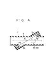
- Fig. 4 shows an another arrangement of a measuring conduit of the invention.
- the light beam which transmits through the light transmitting windows 5a and 5b does not cross the cross point of the central line of the conduit 2 and the central line of the ultrasonic beam transmitted and received between the ultrasonic transducers 4a and 4b; however, the light transmitting windows 5a and 5b are attached in the wall of the conduit 2 in the region between the ultrasonic transducers 4a and 4b.
Landscapes
- Health & Medical Sciences (AREA)
- General Health & Medical Sciences (AREA)
- Pulmonology (AREA)
- Engineering & Computer Science (AREA)
- Anesthesiology (AREA)
- Biomedical Technology (AREA)
- Heart & Thoracic Surgery (AREA)
- Hematology (AREA)
- Public Health (AREA)
- Animal Behavior & Ethology (AREA)
- Emergency Medicine (AREA)
- Life Sciences & Earth Sciences (AREA)
- Veterinary Medicine (AREA)
- Physics & Mathematics (AREA)
- Electromagnetism (AREA)
- Fluid Mechanics (AREA)
- General Physics & Mathematics (AREA)
- Investigating Or Analysing Materials By Optical Means (AREA)
- Investigating Or Analyzing Materials By The Use Of Ultrasonic Waves (AREA)
- Measuring Volume Flow (AREA)
- Measurement Of The Respiration, Hearing Ability, Form, And Blood Characteristics Of Living Organisms (AREA)
Abstract
Description
- The present invention relates to a measuring conduit which is used to simultaneously measure the flow rate of a fluid such as a respiratory gas and the concentration of a particular component in the fluid.
- In the case of a fluid containing various kinds of components, there is often a demand for the measurement of the flow rate of a particular component. For example, when air or gas in which oxygen is artificially added to the air, such as a respiratory gas, is inhaled and the gas containing carbon dioxide is exhaled, the flow rate of carbon dioxide in the expiratory gas is used as carbon dioxide production for the evaluation of a respiration function.
- A method which has been conventionally performed to measure carbon dioxide production is called the Douglas bag method. According to this method, an expired gas is collected into an airtight bag, and the product of its volume v and the carbon dioxide concentration FC02 is obtained. Finally, carbon dioxide production is determined by the average value during measuring period.
- Due to the recent advancement in methods for measuring the flow rate of a fluid and for analyzing a component, the real-time measurement of the flow rate of the component has been made possible. For instance, to measure carbon dioxide production VC02(t), the instantaneous flow rate v(t) of expired gas and the instantaneous concentration of carbon dioxide FC02(t) are simultaneously measured, and carbon dioxide production VC02(t) is computed in the form of:

- The flow-rate measurement and the concentration measurement are each performed while a fluid is flowing through a measuring conduit. To measure the flow rate and the concentration at a time, therefore, a measuring conduit for measuring the flow rate and a measuring conduit for measuring the concentration must be coupled in tandem. However, such a coupling of two measuring conduits makes the dead space in the respiration circuit fairly large. The resultant dead space equals the sum of the capacities of the measuring conduits. This puts a great burden on the respiratory organ of an examinee, causing difficulty in the examination of a serious patient.
- In addition, the tandem coupling of the measuring conduits also causes a problem of measurement accuracy. A reason for such a problem is that both measuring times are slightly different due to the distance between two measuring points. Namely, assuming that the distance from the flow-rate measuring point to the concentration measuring point is L and a flow velocity of the fluid is V, the time td (time difference) required for a lump of fluid undergoing the flow-rate measurement to reach the concentration measuring point is given by:


- It is an object of the present invention to provide a measuring conduit which enables the simultaneous measurements of the flow rate of a fluid containing a measured component and the concentration of the component.
- Another object of the invention is to provide a measuring conduit adapted to measure the flow rate of a respiratory gas and the concentration of a gas component in the respiratory gas with as little as possible dead space in order to lighten the burden of a patient.
- Still another object of the invention is to provide a measuring conduit adapted to measure the flow rate of a respiratory gas and the concentration of a gas component in the respiratory gas without causing a substantial time difference between the measurements.
- The present invention is applied to a measuring conduit which is adapted to measure the flow rate of a fluid in an ultrasonic measuring manner, and the concentration of a particular gas component in the fluid in an optical measuring manner. The measuring conduit of the present invention comprises a single conduit through which a fluid flows; two ultrasonic transducers for measuring the flow rate of the fluid which are attached to the conduit so as to face each other along a line slanted with respect to the flow direction of the fluid; and a pair of light transmitting windows which are airtightly provided in walls of the conduit positioned between the ultrasonic transducers so as to face each other. One of the light transmitting windows introduces light from an external light source into the conduit, and the light transmitted through the fluid flowing through the conduit goes through the other light transmitting window and into a photo detecting element in an external concentration measuring apparatus.
- Preferably, the two ultrasonic transducers and the two light transmitting windows are arranged so that the crossing point of the central line of the axis of the conduit and the central line of the ultrasonic beam which is transmitted and received between the ultrasonic transducers coincides with the central line of the light beam which passes through the pair of light transmitting windows.
- According to the present invention, the flow rate and concentration measurements are performed at substantially the same locations in the conduit; in other words, they are performed almost simultaneously. Therefore, a time difference between the flow rate measurement and the concentration measurement can be minimized. Further, since the flow rate and the concentration can be measured by use of a single conduit with little dead space, the burden for a patient is remarkably reduced.
- This invention can be more fully understood from the following detailed description when taken in conjunction with the accompanying drawings, in which:
- Fig. 1 shows an apparatus for measuring the flow rate and concentration of a fluid which includes a measuring conduit embodying the present invention;
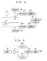
- Fig. 2 is a block diagram of a measuring apparatus for measuring the flow rate of a fluid flowing through the conduit;
- Fig. 3 is a block diagram showing a concentration measuring apparatus for a particular component which is contained in the fluid to be measured; and
- Fig. 4 illustrates a modified form of the measuring conduit of the invention.
- Referring to Fig. 1, a reference numeral 1 denotes a measuring conduit (about 8 cm long) adapted for simultaneously measuring the flow rate and concentration. Ultrasonic transducers for measuring the flow rate and an optical sensor for measuring the concentration are associated with a
conduit member 2 through which a fluid to be measured, for example, a respiratory gas, flows. Themember 2 has a inner diameter of 13 mm and is made of a chemical-resistant, transparent resin such as a polysulfone, which permits the observation of its inner stains. That is, a pair ofultrasonic transducers conduit 2. Theultrasonic transducers conduit 2 so as to protrude therein; however, in the embodiment,recesses conduit 2 and theultrasonic transducers - On the other hand, a pair of light transmitting
windows 5a and 5b made of sapphire are airtightly attached to wall of theconduit 2 in a region between theultrasonic transducers windows 5a and 5b are provided to transmit light for measuring the concentration. In the embodiment, theultrasonic transducers windows 5a and 5b are arranged in a manner such that the central line of a light beam passing through the light transmittingwindows 5a and 5b crosses the cross point P of the central line of the axis of theconduit 2 and the central line of the ultrasonic wave beam which is transmitted and received between theultrasonic transducers - The apparatus for simultaneously measuring the flow rate and the concentration is constituted as follows. A flow measuring circuit 6 is connected to the pair of
ultrasonic transducers - A basic arrangement of the flow rate measurement based on the propagation time difference method will be described with reference to Fig. 2.
- The
ultrasonic transducers drivers conduit member 2 are received by the otherultrasonic transducers receivers 22a and 22b. These signals are sent to a timedifference calculating circuit 24 throughwaveform shaping circuits 23a and 23b, thereby obtaining the propagation time difference between the ultrasonic wave propagating vice versa. By multiplying this difference by a predetermined constant, the flow-rate signal V(t) is derived. - On the other hand, the concentration is measured based on the principle disclosed in, for example, Japanese Laid-Open Patent publication No. 23843/82. That is, a
light source 8 which is lit by a power source 7 is provided on the outside of the light transmitting window 5a. The light from thelight source 8 is introduced into theconduit 2 through the light transmitting window 5a. The light introduced into theconduit 2 is transmitted through the fluid flowing through theconduit 2, and thereafter it is led to the outside through the otherlight transmitting window 5b. The light introduced to the outside reaches arotatable chopper 10 which is driven at a constant rotating speed by a motor 9. Afirst filter 11 and asecond filter 12 are arranged in therotatable chopper 10 at different locations in the circumferential direction. Thefirst filter 11 transmits only the light of a wavelength which is absorbed by a particular component, e.g., carbon dioxide contained in the fluid. Thesecond filter 12 transmits light of which is not absorbed by any components contained in the fluid. The light transmitted through thefilters detector 13 by which they are converted to an electrical signal. Thereafter, the signal is supplied to a componentconcentration measuring circuit 14. - The concentration measuring
circuit 14 is constituted as shown in, for instance, Fig. 3. After a pulse output signal from the photo-detector 13 is amplified by anamplifier 31, it is applied to first and secondsynchronous detectors 32a and 32b. The peak value of the pulse signal indicating the light amount transmitted through thefirst filter 11 and the peak value of the pulse signal representing the light amount transmitted through thesecond filter 12 are respectively detected by thesynchronous detectors 32a and 32b synchronously with the rotation of therotatable chopper 10. The ratio between the peak values of the pulse signals detected by thedetectors 32a and 32b is calculated by adivider 33. Further, an output signal from the divider is amplified by alogarithm amplifier 34, thereby obtaining a signal FC02(t) which indicates the concentration of a particular component, e.g., carbon dioxide. - In this way, the flow rate signal v(t) and the concentration signal FCn2(t) are simultaneously derived from the flow measuring circuit 6 and the component
concentration measuring circuit 14, respectively. - As described above, according to the present invention, the flow rate and the concentration of a particular component can be simultaneously measured by the same measuring conduit, so that the dead space of the overall measuring system to the fluid can be made smaller than when individual measuring conduits are coupled in tandem. Thus, the burden for a patient is largely reduced. This provides a great advantage in performing a respiration control for a serious patient.
- In addition, since the measurements of the flow rate and the concentration of a component are performed by the same measuring conduit, these measuring points are close, so that the time difference in both measurements remarkably reduces. Consequently, there is an advantage such that the signal processing for measurement is simplified. In particular, in the foregoing embodiment, the flow measuring point and the component concentration measuring point coincide with each other at the cross point of the central line of the axis of the conduit member and the central line of the ultrasonic beam which is transmitted and received between the pair of ultrasonic transducers, so that this time difference becomes substantially zero. Therefore, it is not necessary at all to perform a processing of the correction for such time difference.
- It is not always necessary that the flow measuring point and the component concentration measuring point accurately coincide. An almost similar effect will be obtained even if the cross point of the central line of the axis of the conduit and the central line of the ultrasonic beam transmitted and received between the ultrasonic transducers crosses a part of the light beam which transmits through the light transmitting windows.
- Further, in the above embodiment, the plane defined by the central line of the
conduit member 2 and the central line of the ultrasonic beam substantially coincides with the plane defined by the central line of the light beam and the central line of theconduit member 2. In other words, theultrasonic transducers light transmitting windows 5a and 5b are located on a plane on which the central line of theconduit member 2 extends. Therefore, by disposing the measuring conduit 1 so that this plane is set horizontally, even in the case when the fluid flowing through theconduit member 2 is a gas such as a respiratory gas and where such a gas is liquefied in theconduit 2 and the resulting liquid remains in the bottom portion, neither the ultrasonic wave nor the light transmitting thewindows 5a and 5b is not blocked by the liquid. Thus, the propagation of the ultrasonic wave and the transmission of the light are not adversely affected, and the measurement can be stably executed. - Fig. 4 shows an another arrangement of a measuring conduit of the invention. In this embodiment, the light beam which transmits through the
light transmitting windows 5a and 5b does not cross the cross point of the central line of theconduit 2 and the central line of the ultrasonic beam transmitted and received between theultrasonic transducers light transmitting windows 5a and 5b are attached in the wall of theconduit 2 in the region between theultrasonic transducers conduit 2 between theultrasonic transducers
Claims (4)
Applications Claiming Priority (2)
| Application Number | Priority Date | Filing Date | Title |
|---|---|---|---|
| JP226131/83 | 1983-11-30 | ||
| JP58226131A JPS60117131A (en) | 1983-11-30 | 1983-11-30 | Measuring tube for simultaneously measuring flow rate and concentration of fluid |
Publications (3)
| Publication Number | Publication Date |
|---|---|
| EP0145384A2 true EP0145384A2 (en) | 1985-06-19 |
| EP0145384A3 EP0145384A3 (en) | 1986-02-26 |
| EP0145384B1 EP0145384B1 (en) | 1989-01-25 |
Family
ID=16840327
Family Applications (1)
| Application Number | Title | Priority Date | Filing Date |
|---|---|---|---|
| EP84308135A Expired EP0145384B1 (en) | 1983-11-30 | 1984-11-23 | Measuring conduit for flow rate and concentration of fluid |
Country Status (4)
| Country | Link |
|---|---|
| US (1) | US4581942A (en) |
| EP (1) | EP0145384B1 (en) |
| JP (1) | JPS60117131A (en) |
| DE (1) | DE3476451D1 (en) |
Cited By (4)
| Publication number | Priority date | Publication date | Assignee | Title |
|---|---|---|---|---|
| US5816242A (en) * | 1995-05-05 | 1998-10-06 | Siemens Elema Ab | Device for transmitting information via a patient tube in an intensive care or anesthetic machine |
| EP0874238A1 (en) * | 1997-04-21 | 1998-10-28 | Siemens-Elema AB | A measuring device for simultaneous determination of the flow in a circulating gasmixture and the concentration of a specific gas in the gas mixture |
| US6095986A (en) * | 1998-07-28 | 2000-08-01 | Square One Technology, Inc. | Disposable anti-fog airway adapter |
| WO2010040332A1 (en) * | 2008-10-07 | 2010-04-15 | Ganshorn Medizin Electronic Gmbh | Method for measuring dead lung space |
Families Citing this family (33)
| Publication number | Priority date | Publication date | Assignee | Title |
|---|---|---|---|---|
| FI82367C (en) * | 1988-02-11 | 1991-03-11 | Instrumentarium Oy | Spirometer coupled to intubation tube and sampling connection in g asanalyzer |
| US5029584A (en) * | 1989-09-21 | 1991-07-09 | Cornelius Smith | Method and apparatus for measuring patient blood loss |
| US5060514A (en) * | 1989-11-30 | 1991-10-29 | Puritan-Bennett Corporate | Ultrasonic gas measuring device |
| US5369998A (en) * | 1989-12-12 | 1994-12-06 | Commonwealth Scientific And Industrial Research Organisation | Ultrasonic mass flow meter for solids suspended in a gas stream |
| US5115670A (en) * | 1990-03-09 | 1992-05-26 | Chevron Research & Technology Company | Measurement of fluid properties of two-phase fluids using an ultrasonic meter |
| US5067492A (en) * | 1990-08-07 | 1991-11-26 | Critikon, Inc. | Disposable airway adapter |
| DE4140572C2 (en) * | 1990-12-10 | 1995-09-21 | Heinz Selic | Method for determining the flow rate of a flowing medium that is temporarily available as a one- or two-phase flow |
| US5287851A (en) * | 1991-09-11 | 1994-02-22 | Beran Anthony V | Endotracheal tube connector with integral pneumotach transducer |
| US5456102A (en) * | 1993-03-19 | 1995-10-10 | Moorehead; Jack | Method and apparatus for particle counting and counter calibration |
| US5585729A (en) * | 1993-05-13 | 1996-12-17 | Gamma Precision Technology, Inc. | Fluid concentration detecting apparatus |
| DE4318690A1 (en) * | 1993-06-04 | 1995-01-05 | Ndd Medizintechnik Gmbh | Method for measuring the molar mass of gases or gas mixtures and device for carrying out this method |
| EP0646346A3 (en) * | 1993-09-30 | 1998-06-17 | NDD Medizintechnik GmbH | Device for measuring respiratory gas parameters |
| US5789660A (en) * | 1996-07-15 | 1998-08-04 | Novametrix Medical Systems, Inc. | Multiple function airway adapter |
| US7335164B2 (en) | 1996-07-15 | 2008-02-26 | Ntc Technology, Inc. | Multiple function airway adapter |
| US20070225612A1 (en) * | 1996-07-15 | 2007-09-27 | Mace Leslie E | Metabolic measurements system including a multiple function airway adapter |
| SE9801430D0 (en) | 1998-04-23 | 1998-04-23 | Siemens Elema Ab | Ultrasonic flowmeter |
| JP2002529183A (en) * | 1998-11-17 | 2002-09-10 | ジェームズ アール モールト | Invasive determination method and apparatus for cardiac output |
| US7168597B1 (en) * | 1999-03-12 | 2007-01-30 | Smithkline Beecham Corporation | Aerosol metering valve |
| DE19944047C2 (en) * | 1999-09-14 | 2003-09-25 | Schubert & Salzer Control Syst | Device for measuring concentration or density as well as particles |
| DE10106046A1 (en) * | 2001-02-09 | 2002-08-29 | Draeger Medical Ag | Combined breath flow sensor |
| SE0301226D0 (en) * | 2003-04-28 | 2003-04-28 | Siemens Elema Ab | Acoustic Determination of Moisture Content of a Gas Mixture |
| DE10352652A1 (en) * | 2003-11-12 | 2005-06-30 | Dräger Medical AG & Co. KGaA | Breathing apparatus breath flow volume sensor has bidirectional ultrasonic sensor in fY piece flow chamber |
| US8146592B2 (en) * | 2004-02-26 | 2012-04-03 | Ameriflo, Inc. | Method and apparatus for regulating fluid flow or conserving fluid flow |
| US7617826B1 (en) | 2004-02-26 | 2009-11-17 | Ameriflo, Inc. | Conserver |
| US7448594B2 (en) | 2004-10-21 | 2008-11-11 | Ameriflo, Inc. | Fluid regulator |
| DE102008060922A1 (en) * | 2008-12-06 | 2010-06-10 | Ganshorn Medizin Electronic Gmbh | Lung diagnostic device with two ultrasonic measuring sections |
| DE102008063503A1 (en) * | 2008-12-17 | 2010-08-05 | Ganshorn Medizin Electronic Gmbh | Lung diagnostic device with four ultrasonic elements |
| US10508937B2 (en) * | 2012-04-12 | 2019-12-17 | Texas Instruments Incorporated | Ultrasonic flow meter |
| DE102013114475B4 (en) * | 2013-12-19 | 2021-04-08 | Sick Ag | Ultrasonic measuring device and method for determining the flow velocity |
| US10393638B2 (en) * | 2014-01-29 | 2019-08-27 | Jp3 Measurement, Llc | System and method for determining vapor pressure of produced hydrocarbon streams via spectroscopy |
| DE102014111732A1 (en) * | 2014-08-18 | 2016-02-18 | Endress + Hauser Flowtec Ag | Field device for automation technology |
| CN110291391B (en) * | 2017-01-30 | 2023-10-27 | 乔杜里·F·拉希姆 | Ultrasonic gas sensor system using machine learning |
| US10610659B2 (en) | 2017-03-23 | 2020-04-07 | General Electric Company | Gas mixer incorporating sensors for measuring flow and concentration |
Citations (3)
| Publication number | Priority date | Publication date | Assignee | Title |
|---|---|---|---|---|
| JPS5723843A (en) * | 1980-07-21 | 1982-02-08 | Nippon Koden Corp | Measuring apparatus of concentration of respiratory gas |
| EP0051293A1 (en) * | 1980-10-31 | 1982-05-12 | Kabushiki Kaisha Toshiba | Respiration flowmeter |
| EP0072770A1 (en) * | 1981-08-18 | 1983-02-23 | DEUTSCHE FORSCHUNGSANSTALT FÜR LUFT- UND RAUMFAHRT e.V. | Method and apparatus for measuring transit time differences of ultrasonic pulses for determining flow patterns |
Family Cites Families (6)
| Publication number | Priority date | Publication date | Assignee | Title |
|---|---|---|---|---|
| US3901078A (en) * | 1973-09-07 | 1975-08-26 | Westinghouse Electric Corp | Ultrasonic system for fluid flow measurement |
| US3906791A (en) * | 1973-10-01 | 1975-09-23 | Panametrics | Area averaging ultrasonic flowmeters |
| JPS5250784A (en) * | 1975-10-22 | 1977-04-23 | Yokogawa Hokushin Electric Corp | Ultrasonic type flow and density meter |
| JPS5418065A (en) * | 1977-07-11 | 1979-02-09 | Toko Inc | Method of making smalllsize high frequency coil |
| JPS5777914A (en) * | 1980-10-31 | 1982-05-15 | Toshiba Corp | Fluid measuring apparatus |
| JPS58223040A (en) * | 1982-06-22 | 1983-12-24 | Nippon Koden Corp | Apparatus for measuring concentration of respiration gas |
-
1983
- 1983-11-30 JP JP58226131A patent/JPS60117131A/en active Pending
-
1984
- 1984-11-23 EP EP84308135A patent/EP0145384B1/en not_active Expired
- 1984-11-23 DE DE8484308135T patent/DE3476451D1/en not_active Expired
- 1984-11-27 US US06/675,231 patent/US4581942A/en not_active Expired - Lifetime
Patent Citations (3)
| Publication number | Priority date | Publication date | Assignee | Title |
|---|---|---|---|---|
| JPS5723843A (en) * | 1980-07-21 | 1982-02-08 | Nippon Koden Corp | Measuring apparatus of concentration of respiratory gas |
| EP0051293A1 (en) * | 1980-10-31 | 1982-05-12 | Kabushiki Kaisha Toshiba | Respiration flowmeter |
| EP0072770A1 (en) * | 1981-08-18 | 1983-02-23 | DEUTSCHE FORSCHUNGSANSTALT FÜR LUFT- UND RAUMFAHRT e.V. | Method and apparatus for measuring transit time differences of ultrasonic pulses for determining flow patterns |
Non-Patent Citations (1)
| Title |
|---|
| PATENTS ABSTRACTS OF JAPAN, vol. 6, no. 88 (P-118) [966], 26th May 1982; & JP-A-57 023 843 (NIPPON KOUDEN KOGYO K.K.) 08-02-1982 * |
Cited By (4)
| Publication number | Priority date | Publication date | Assignee | Title |
|---|---|---|---|---|
| US5816242A (en) * | 1995-05-05 | 1998-10-06 | Siemens Elema Ab | Device for transmitting information via a patient tube in an intensive care or anesthetic machine |
| EP0874238A1 (en) * | 1997-04-21 | 1998-10-28 | Siemens-Elema AB | A measuring device for simultaneous determination of the flow in a circulating gasmixture and the concentration of a specific gas in the gas mixture |
| US6095986A (en) * | 1998-07-28 | 2000-08-01 | Square One Technology, Inc. | Disposable anti-fog airway adapter |
| WO2010040332A1 (en) * | 2008-10-07 | 2010-04-15 | Ganshorn Medizin Electronic Gmbh | Method for measuring dead lung space |
Also Published As
| Publication number | Publication date |
|---|---|
| EP0145384A3 (en) | 1986-02-26 |
| EP0145384B1 (en) | 1989-01-25 |
| JPS60117131A (en) | 1985-06-24 |
| US4581942A (en) | 1986-04-15 |
| DE3476451D1 (en) | 1989-03-02 |
Similar Documents
| Publication | Publication Date | Title |
|---|---|---|
| EP0145384B1 (en) | Measuring conduit for flow rate and concentration of fluid | |
| US5645071A (en) | Method for the measurement of the molar mass of gases or gas mixtures and an apparatus for the performance of the method | |
| US5479019A (en) | Apparatus for determining the 13 CO2 /12 CO2 ratio of concentrations in a gas sample | |
| EP0551142B1 (en) | Improved multichannel gas analyzer | |
| US5282473A (en) | Sidestream infrared gas analyzer requiring small sample volumes | |
| US6493567B1 (en) | Single light sensor optical probe for monitoring blood parameters and cardiovascular measurements | |
| US7734322B2 (en) | Blood volume determination and sensor calibration | |
| US4902896A (en) | Infrared fluid analyzer | |
| US7235054B2 (en) | Measuring head for a gas analyser | |
| US9849225B2 (en) | Self calibrating blood chamber | |
| JPS6258251B2 (en) | ||
| EP0405841A2 (en) | Method and apparatus for gas analysis | |
| CN104970795A (en) | Device for measurement and analysis of multiple breath nitrogen washout process | |
| JPH11290452A (en) | Dialysis liquid supply device and monitoring method for selected dialysis liquid parameter | |
| EP1764036A1 (en) | Method for the determination of the time-delay between a main-stream ultrasonic flow sensor and a side-stream gas analyzer | |
| US20030188580A1 (en) | Acoustic gas monitor | |
| JP2012239690A (en) | Oxygen meter using ultrasonic flowmeter | |
| US7127936B2 (en) | Acoustic analysis of gas mixtures | |
| JPS60117149A (en) | Apparatus for measuring flow rate of component | |
| JP2580585Y2 (en) | Pure water dilution sampling device | |
| JPS60227733A (en) | Respiration monitor apparatus | |
| GB2084321A (en) | Apparatus for Measuring Respiratory Replacement | |
| JPH09276270A (en) | Bloodstream measuring device | |
| CN117045231A (en) | Turbine type multifunctional spirometer | |
| JPS61359A (en) | Respiration monitor apparatus |
Legal Events
| Date | Code | Title | Description |
|---|---|---|---|
| PUAI | Public reference made under article 153(3) epc to a published international application that has entered the european phase |
Free format text: ORIGINAL CODE: 0009012 |
|
| 17P | Request for examination filed |
Effective date: 19841204 |
|
| AK | Designated contracting states |
Designated state(s): DE FR GB NL SE |
|
| PUAL | Search report despatched |
Free format text: ORIGINAL CODE: 0009013 |
|
| AK | Designated contracting states |
Designated state(s): DE FR GB NL SE |
|
| 17Q | First examination report despatched |
Effective date: 19871021 |
|
| GRAA | (expected) grant |
Free format text: ORIGINAL CODE: 0009210 |
|
| AK | Designated contracting states |
Kind code of ref document: B1 Designated state(s): DE FR GB NL SE |
|
| REF | Corresponds to: |
Ref document number: 3476451 Country of ref document: DE Date of ref document: 19890302 |
|
| ET | Fr: translation filed | ||
| PLBE | No opposition filed within time limit |
Free format text: ORIGINAL CODE: 0009261 |
|
| STAA | Information on the status of an ep patent application or granted ep patent |
Free format text: STATUS: NO OPPOSITION FILED WITHIN TIME LIMIT |
|
| 26N | No opposition filed | ||
| EAL | Se: european patent in force in sweden |
Ref document number: 84308135.7 |
|
| PGFP | Annual fee paid to national office [announced via postgrant information from national office to epo] |
Ref country code: FR Payment date: 19971008 Year of fee payment: 14 |
|
| PGFP | Annual fee paid to national office [announced via postgrant information from national office to epo] |
Ref country code: GB Payment date: 19971114 Year of fee payment: 14 |
|
| PGFP | Annual fee paid to national office [announced via postgrant information from national office to epo] |
Ref country code: SE Payment date: 19971117 Year of fee payment: 14 |
|
| PGFP | Annual fee paid to national office [announced via postgrant information from national office to epo] |
Ref country code: NL Payment date: 19971130 Year of fee payment: 14 |
|
| PGFP | Annual fee paid to national office [announced via postgrant information from national office to epo] |
Ref country code: DE Payment date: 19980128 Year of fee payment: 14 |
|
| PG25 | Lapsed in a contracting state [announced via postgrant information from national office to epo] |
Ref country code: GB Free format text: LAPSE BECAUSE OF NON-PAYMENT OF DUE FEES Effective date: 19981123 |
|
| PG25 | Lapsed in a contracting state [announced via postgrant information from national office to epo] |
Ref country code: SE Free format text: LAPSE BECAUSE OF NON-PAYMENT OF DUE FEES Effective date: 19981124 |
|
| PG25 | Lapsed in a contracting state [announced via postgrant information from national office to epo] |
Ref country code: NL Free format text: LAPSE BECAUSE OF NON-PAYMENT OF DUE FEES Effective date: 19990601 |
|
| GBPC | Gb: european patent ceased through non-payment of renewal fee |
Effective date: 19981123 |
|
| PG25 | Lapsed in a contracting state [announced via postgrant information from national office to epo] |
Ref country code: FR Free format text: LAPSE BECAUSE OF NON-PAYMENT OF DUE FEES Effective date: 19990730 |
|
| EUG | Se: european patent has lapsed |
Ref document number: 84308135.7 |
|
| NLV4 | Nl: lapsed or anulled due to non-payment of the annual fee |
Effective date: 19990601 |
|
| REG | Reference to a national code |
Ref country code: FR Ref legal event code: ST |
|
| PG25 | Lapsed in a contracting state [announced via postgrant information from national office to epo] |
Ref country code: DE Free format text: LAPSE BECAUSE OF NON-PAYMENT OF DUE FEES Effective date: 19990901 |