EP0155857A2 - Knee laxity evaluator and motion module/digitizer arrangement - Google Patents
Knee laxity evaluator and motion module/digitizer arrangement Download PDFInfo
- Publication number
- EP0155857A2 EP0155857A2 EP85400145A EP85400145A EP0155857A2 EP 0155857 A2 EP0155857 A2 EP 0155857A2 EP 85400145 A EP85400145 A EP 85400145A EP 85400145 A EP85400145 A EP 85400145A EP 0155857 A2 EP0155857 A2 EP 0155857A2
- Authority
- EP
- European Patent Office
- Prior art keywords
- link arm
- motion
- transducer
- point
- measuring
- Prior art date
- Legal status (The legal status is an assumption and is not a legal conclusion. Google has not performed a legal analysis and makes no representation as to the accuracy of the status listed.)
- Ceased
Links
Images


Classifications
-
- A—HUMAN NECESSITIES
- A61—MEDICAL OR VETERINARY SCIENCE; HYGIENE
- A61B—DIAGNOSIS; SURGERY; IDENTIFICATION
- A61B5/00—Measuring for diagnostic purposes; Identification of persons
- A61B5/103—Detecting, measuring or recording devices for testing the shape, pattern, colour, size or movement of the body or parts thereof, for diagnostic purposes
-
- A—HUMAN NECESSITIES
- A61—MEDICAL OR VETERINARY SCIENCE; HYGIENE
- A61B—DIAGNOSIS; SURGERY; IDENTIFICATION
- A61B5/00—Measuring for diagnostic purposes; Identification of persons
- A61B5/45—For evaluating or diagnosing the musculoskeletal system or teeth
- A61B5/4528—Joints
-
- A—HUMAN NECESSITIES
- A61—MEDICAL OR VETERINARY SCIENCE; HYGIENE
- A61B—DIAGNOSIS; SURGERY; IDENTIFICATION
- A61B5/00—Measuring for diagnostic purposes; Identification of persons
- A61B5/103—Detecting, measuring or recording devices for testing the shape, pattern, colour, size or movement of the body or parts thereof, for diagnostic purposes
- A61B5/11—Measuring movement of the entire body or parts thereof, e.g. head or hand tremor, mobility of a limb
- A61B5/1107—Measuring contraction of parts of the body, e.g. organ, muscle
-
- A—HUMAN NECESSITIES
- A61—MEDICAL OR VETERINARY SCIENCE; HYGIENE
- A61B—DIAGNOSIS; SURGERY; IDENTIFICATION
- A61B5/00—Measuring for diagnostic purposes; Identification of persons
- A61B5/22—Ergometry; Measuring muscular strength or the force of a muscular blow
-
- G—PHYSICS
- G01—MEASURING; TESTING
- G01B—MEASURING LENGTH, THICKNESS OR SIMILAR LINEAR DIMENSIONS; MEASURING ANGLES; MEASURING AREAS; MEASURING IRREGULARITIES OF SURFACES OR CONTOURS
- G01B7/00—Measuring arrangements characterised by the use of electric or magnetic techniques
- G01B7/004—Measuring arrangements characterised by the use of electric or magnetic techniques for measuring coordinates of points
-
- G—PHYSICS
- G01—MEASURING; TESTING
- G01B—MEASURING LENGTH, THICKNESS OR SIMILAR LINEAR DIMENSIONS; MEASURING ANGLES; MEASURING AREAS; MEASURING IRREGULARITIES OF SURFACES OR CONTOURS
- G01B7/00—Measuring arrangements characterised by the use of electric or magnetic techniques
- G01B7/30—Measuring arrangements characterised by the use of electric or magnetic techniques for measuring angles or tapers; for testing the alignment of axes
-
- A—HUMAN NECESSITIES
- A61—MEDICAL OR VETERINARY SCIENCE; HYGIENE
- A61B—DIAGNOSIS; SURGERY; IDENTIFICATION
- A61B2562/00—Details of sensors; Constructional details of sensor housings or probes; Accessories for sensors
- A61B2562/04—Arrangements of multiple sensors of the same type
- A61B2562/046—Arrangements of multiple sensors of the same type in a matrix array
-
- A—HUMAN NECESSITIES
- A61—MEDICAL OR VETERINARY SCIENCE; HYGIENE
- A61B—DIAGNOSIS; SURGERY; IDENTIFICATION
- A61B5/00—Measuring for diagnostic purposes; Identification of persons
- A61B5/68—Arrangements of detecting, measuring or recording means, e.g. sensors, in relation to patient
- A61B5/6801—Arrangements of detecting, measuring or recording means, e.g. sensors, in relation to patient specially adapted to be attached to or worn on the body surface
- A61B5/6813—Specially adapted to be attached to a specific body part
- A61B5/6828—Leg
-
- A—HUMAN NECESSITIES
- A61—MEDICAL OR VETERINARY SCIENCE; HYGIENE
- A61B—DIAGNOSIS; SURGERY; IDENTIFICATION
- A61B5/00—Measuring for diagnostic purposes; Identification of persons
- A61B5/68—Arrangements of detecting, measuring or recording means, e.g. sensors, in relation to patient
- A61B5/6801—Arrangements of detecting, measuring or recording means, e.g. sensors, in relation to patient specially adapted to be attached to or worn on the body surface
- A61B5/6813—Specially adapted to be attached to a specific body part
- A61B5/6829—Foot or ankle
-
- A—HUMAN NECESSITIES
- A61—MEDICAL OR VETERINARY SCIENCE; HYGIENE
- A61B—DIAGNOSIS; SURGERY; IDENTIFICATION
- A61B5/00—Measuring for diagnostic purposes; Identification of persons
- A61B5/70—Means for positioning the patient in relation to the detecting, measuring or recording means
- A61B5/702—Posture restraints
-
- Y—GENERAL TAGGING OF NEW TECHNOLOGICAL DEVELOPMENTS; GENERAL TAGGING OF CROSS-SECTIONAL TECHNOLOGIES SPANNING OVER SEVERAL SECTIONS OF THE IPC; TECHNICAL SUBJECTS COVERED BY FORMER USPC CROSS-REFERENCE ART COLLECTIONS [XRACs] AND DIGESTS
- Y10—TECHNICAL SUBJECTS COVERED BY FORMER USPC
- Y10S—TECHNICAL SUBJECTS COVERED BY FORMER USPC CROSS-REFERENCE ART COLLECTIONS [XRACs] AND DIGESTS
- Y10S482/00—Exercise devices
- Y10S482/901—Exercise devices having computer circuitry
Definitions
- the invention relates to a novel knee laxity evaluator (KLE) system.
- the invention also relates to a motion module/digitizer combination which can be used in the KLE, or which can be used independently or in other systems. More specifically, the invention relates to such a combination which can measure, in three dimensional space, and relative to the position of a first point or body or coordinate system, position or motion of a second point or body, as well as position or motion of the second point or body relative to a third, fourth, fifth ... nth points, or positions of the second body, or combinations thereof.
- a KLE includes a motion module, that is, a module for measuring, in three dimensional space, movement of a point or body relative to a fixed point or body.
- Modules of this type are known in the art as is illustrated, for example, in U.S. Patent 3 944 798, Eaton, March 16, 1976, U.S. Patent 4 057 806, Furnadjiev et al, November 8, 1977, and U.S. Patent 4 205 308, Haley et al, May 27, 1980.
- a knee laxity evaluator comprises an instrumented seat for seating a patient and restraint means for restraining a portion of the patient to the instrumented seat whereby to measure forces applied to the patient at an unrestrained part thereof.
- Motion module means measure the motion of the unrestrained part of the patient relative to the restrained part thereof, and processor means analyze outputs of the instrumented seat and the motion module means and provide indications of applied force and motion of the unrestrained part relative to the restrained part.
- a motion module/digitizer combination comprises an elongated member having a first end and a second end and comprising a first link arm and a second link arm and means movably connecting the first link arm to the second link arm so as to permit translation motion between the first end and the second end, the means for connecting being disposed intermediate the first and second ends, the means also including first transducer means for measuring the translational motion.
- First mounting means are provided at the first end for mounting the first end at a first point, body or coordinate system and second mounting means are provided at the second end for mounting the second end at a second point or body.
- Second transducer means are provided at the first end for measuring three dimendio- nal rotational motion of the first link arm relative to the first point or body and a third transducer means is provided at the second end for measuring three dimensional rotational motion of the second link arm relative to the second point or body.
- a portion of the second link arm is detachable from the remainder of the second link arm and the second mounting means and means are connectable to the remainder of the second link arm.
- measurements can be performed to determine the position in space of the second point or body relative to the position of the first point or body or the position in space of the second point or body relative to the third, fourth, fifth ... nth points or positions of the second body or combinations thereof.
- a dynanometer for determining the magnitude and direction of an applied force.
- the dynanometer includes three spaced beams and support means on each of the beams.
- Platform means are disposed on and supported by the support means for receiving and being deflected by the applied force. The deflection of the platform is transmitted to the beams to cause deflection of the beams.
- Means are provided for measuring the deflection of the beams in two directions thereof.
- the beams are arranged such that no two redundant directions of deflection of the beams are permissible.
- the KLE system includes a thigh restraint means 7, an instrumented seat 9 and a motion module 11.
- the motion module is connected at one end 13 to the instrumented seat which, as will be seen below, constitutes a fixed point or body.
- the other end 15 is connected to a second point or body.
- the purpose of the instrument is to determine the movement of the second point or body relative to the first point or body in three dimensional space.
- the instrumented seat may be mounted on an examining table 17 and consists of a dynanometer 19 which measures applied forces. Instruments for measuring force are described in MEASUREMENT SYSTEMS : APPLICATION AND DESIGN by E. 0. Doebelin, McGraw Hill, pps. 333-350.
- the instrumented seat may also have an adjustable seat back arrangement 18 as is well known in the art.
- the thigh restraint 7 comprises two or mode pairs of off-set straps, which are fastened to each other by fastening means 8, and which displace soft tissue and may also provide a torquing of the tissue about the femur in order to minimize movement of the femur relative to the seat.
- the lower leg attachment illustrated best in Figures 4 and 5, comprises a strap member 21, for example a velcro strap on which is carried the attachment 15a for the end 15 of the motion module.
- the lower leg attachment functions by referencing the motion module to three bony pro- minences of the lower leg, namely, the tibial crest 23 and the medial and lateral malleoli, 25 and 27 respectively.
- Rollers 29 align themselves to the bony contours of the tibial crest, and balls in malleolar cups 31 do the same at the malleoli. These balls and rollers allow the skin to move between the attachment of the bone so that the attachment will move only with the bone which is important in attaining a true bone position measurement.
- the system also includes a microprocessor based monitor 33 which receives outputs from the dynanometer and the motion module.
- the KLE is capable of sensing and measuring applied loads of displacements existing during the use of all standard'knee evaluation techniques.
- the present KLE is designed to minimize the effects of soft tissue while still permitting the physician to hold, palpate and manipulate the joint as in normal procedures while the KLE provides accurate applied force and tibial- femoral motion readings in displayed and printed form.
- the dynanometer force plate measures forces and moments in basic directions and permits the physician to know exactly to what levels the knee is being stressed. This is important when measuring laxity since the amount of relative bone motion depends on the.stress applied. Knowledge of the forces is of utmost importance to the objective interpretation of joint laxity.
- the motion module measures the true three dimensional position of the tibia relative to the seat, and hence, as the thigh is restrained, to the femur.
- the motion module is an electromechanical device which functions on the principle that-at least six measurements are required to totally define the position of an object in space as will be further discussed below. It will consist of a means capable of measuring six degrees of freedom, three dimensional motion of one point or body relative to another point or body and preferably comprises a unique arrangement of electronic components capable of measuring rotational or translational displacements. A specific module is described below in association with Figures 6 to 8. Generally speaking, the two points or bodies between which relative motions are being measured are connected by a single rigid telescopic arm, or a single arm having a joint between its two ends.
- the force measurement on the dynanometer is accomplished through the principles of opposite and equal reaction forces.
- the forces applied to the knee of the patient are reacted to by the femur and thigh which are in turn transmitted to the dynanometer.
- knowledge of the relative position of the knee and the dynanometer, provided by the motion module permits a theoretical interpretation of the forces and their representation in the coordinate system of the knee.
- FIG. 6 there is illustrated a particular motion module/digitizer combination which can be used in the KLE environment.
- the combination can be used in other systems or it can be used independently.
- it could be used in association with machine tools and other mechanical systems where it is necessary to be able to measure displacement of a first point or body relative to a second point or body.
- the measurements can constitute six unique rotational measurements or six unique translational measurements or combinations thereof, i. e., four rotational and two translational, etc.
- the combination in accordance with the invention takes five unique measurements of rotational motion and one measurement of translational motion.
- the combination includes an elongated member 101 having a first end 103 and a second end 105.
- the elongated member comprises a first link arm 107 and a second link arm 109.
- the link arms 107 and 109 are joined together at 111 to permit relative translational movement as between 103 and 105 and to measure this translational movement.
- the link arms are connected for pivotal motion whereby to permit remative translational motion of 103 and 105, and a rotary transducer means is used to measure this translational motion as will be discussed below.
- one of the arms could include a sleeve for overlying the other arm and for permitting movement of the other arm into and out of the sleeve.
- a translational transducer means could be included in the sleeve for measuring the translational motion.
- Examples of rotary transducer means which can be used are resistive potentiometers, variable inductance transformers, syncro resolvers, inductance potentiometers and variable reluctance transducers.
- Examples of translational transducers which could be used are dial indicators, resistive potentiometers, variable inductance transformers, capacitance transducers, piezoelectric transducers, ionization transducers and optical transducers.
- a first rotary potentiometer 113 Disposed at the end 103 is a first rotary potentiometer 113 which is disposed in line with the arm 103 and rotatable about an axis at right angles to the arm 103.
- a second rotary potentiometer 115 is disposed at right angles to the potentiometer 113 and is rotatable about an axis at right angles to the axis of the potentiometer 113.
- Potentiometer 115 is mounted on mounting block 117 for mounting the arrangement at one end thereof.
- a third rotary potentiometer 119 Disposed at second end 105 is a third rotary potentiometer 119 which is in line with the second link arm 109 and which rotates about an axis at right angles to the second link arm 109.
- a fourth rotary potentiometer 121 is disposed at right angles to potentiometer 119 and is rotatable about an axis at right angles to the axis of potentiometer 119.
- a fifth rotary potentiometer 123 is also disposed at right angles to potentiometer 119 and is rotatable about an axis at right angles to the axis of potentiometer 119. Potentiometer 123 is also at right angles to potentiometer 121 and its axis of rotation is also at right angles to the axis of potentiometer 121.
- Potentiometer 123 is connected to mounting block 25 for mounting the arrangement at a second point.
- arms 107 and 109 are connected at 111 by a sixth rotary potentiometer 127 which is in line with both arms 107 and 109 and whose axis of rotation is at right angles to both arms 107 and 109.
- the arrangement as thus far described can measure the motion in three dimensional space of end 105 relative to end 103 or vice-versa and is referred to as motion module.
- motion module there is provided the potential for digitizing the positions of third, fourth, fifth ... nth points or bodies (henceforth, the use of the term points will be used and understood to refer to points or bodies) in three dimensional space, or combinations thereof, and of then measuring the motion or position of one of the points 103 or 105 relative to the position of the other point or relative to the third, fourth, fifth ... nth points, or positions of the second body, or combinations thereof.
- This potential is achieved by making one of the link arms disconnectable from its respective mounting block and reconnectable again thereto.
- link arm 109 is disconnectable from mounting block 125.
- the protrusion 129 which extends from potentiometer 119 is insertable into a receptacle 131.
- the protrusion is also removable from the receptacle, and other inserts, such as those illustrated in Figures 8A, 8B, etc. can be inserted into the receptacle for digitizing the positions of other points in space.
- potentiometers 113, 115 and 127 define a spherical coordinate system about O.
- potentiometers 113 and 115 provide the conventional angles e and respectively, while the potentiometer 127, combined with 107 and 109, provide the length of the vector R. (Knowing the length of 107 and 109, and knowing the angle therebetween, it is quite easy to determine the length of the vector R).
- Point B is defined as the intersection of the axes of potentiometers 119, 121 and 123 and is considered the origin of the "moving body" coordinate system.
- 0 is considered to origin of a "fixed" body or coordinate system.
- mounting block 125 would be mounted on a moving body.
- Mounting block 117 would be mounted on the fixed body or coordinate system, and the measurement of the movement of 105 relative to 103 would define the motion of the moving body relative to the fixed body or coordinate system.
- the final description of the moving body motion is contained in the three finite rotations provided by the potentiometers 119, 121 and 123.
- the protrusion 119 is removed from the receptacle 131, and one of the digitizer tips illustrated in Figure 8 is inserted into the receptacle in place of the protrusion 119.
- the tip is then pointed at points of interest, namely, a third, fourth, fifth ... nth points above-mentioned, and a reading is taken of the three dimensional.position in space of these points.
- conductive leads from the potentiometers will be brought to a connecting board, which could be disposed on the mounting blocks 117, so that the electrical signals developed at the potentiometers can be brought to a processing means such as the processing means illustrated schematically at 133 in Figure 1. It will, of course, be necessary to provide DC power to the potentiometer to measure the changing resistance thereof, as well known in the art, and this DC power could also be provided from the processing means 1330
- the potentiometers will provide the data for determining the extent and direction of the motion of point 105. In order to determine the direction and extent, the data must be processed. Preferably, the data is processed by computer means. A flow chart for controlling such a computer is illustrated in Figure 8.
- DIGMAT digital transformation matrix
- DIGIT digitalization
- NEWTIP support routine for user defined tip
- the protrusion 129 is removed from the receptacle 131, and one of a variety of tips is inserted in the receptacle.
- the mounting blocks 117 must be firmly mounted at a position which both permits easy access to most points of interest and is also appropriate for any subsequent motion measurement using both upper and lower components of the motion module. A position of interest is then pointed at with the tip.
- the physical characteristics are inputted into the computer memory, and a code is then presented to the computer to let it know which of the tips is being used.
- the program Upon pointing at the position with the tip, the program must be activated either through a remote switch or a keyboard entry.
- the control program will then scan the signals in the potentiometer, and then in sequence, call the subroutine DIGMAT, which uses as input the voltage values of potentiometers 113, 115 and 127, as well as the voltage of the power supply.
- DIGMAT outputs to transformation matrices which are used in the subroutine digit which is the next subroutine to be called.
- DIGIT actually computes the position of DTIP in the global coordinate system using as input the output of DIGMAT and DTIP coordinates in potentiometer 127 coordinate system.
- the TIP is then removed from the receptacle 131 and the protrusion 129 is again inserted in the receptacle.
- the subroutine LOCTRN which computes the coordinates of the digitized points in the local coordinate system (that is, with the point B as an origin) is then called. These points are then outputted to the GLOTRN subroutine which will be discussed below.
- the mounting block 125 would have been attached to the point of interest. Displacements of this point are performed, and the potentiometer signals are once again scanned. This data is communicated to the computer and the subroutine DISMAT is called. DISMAT computes the contents of the transformation matrix describing the body in three dimensional space. The subroutine GLOTRN is then called and outputs new positions of those points previously digitized on the body or analytically generated points, in the global system. This procedure continues as the point of interest moves through different positions.
- This subroutine computes matrix DT12 as well as matrix DT3 which locates the position of potentiometer-113 and potentiometer-127 coordinate systems, respectively.
- This subroutine computes the coordinates of the digitizer tip with respect to the global coordinate system.
- -DPNTRF (3) are the coordinates of the tip with respect to the global coordinate system. (Note 2 & 3)
- the main purpose of this subroutine is to define the coordinates of any user-designed tip with respect to potentiometer-127 coordinate system without independently measuring the tip dimensions.
- first mount tip number 1 see 8b
- touch a point Note 1
- the coordinates of the point are computed by tip #1 and are used to compute the constants for the new tip.
- DISMAT computes the position of the local coordinate system with respect to the global coordinate system.
- the local coordinate system is in line with indicated edges of upper mounting block.
- DMAT2 (4,3) consists of : DMAT2 (4,1), DMAT2 (4,2) and DMAT2 (4,3) are the coordinates of point B in global coordinate system. DMAT2 (3,3) defines the position of the local coordinate system with respect to the global coordinate system. (Note 1) DMAT2 (4,3) is input only to subroutines LOCTRN and GLOTRN, and has no significance to the user.
- LOCTRN computes the coordinates of the digitized points in local coordinate system.
- 2-In the coordinate arrays 1, 2 and 3 are X, Y and Z coordinates, respectively.
- GLOTRN computes the new coordinates of the points in the global coordinate system.
- the dynanometer comprises a supporting frame 201 which, in the illustrated embodiment, comprises a four walled structure. Disposed centrally of one wall is a first spherical or rectangular beam 203. Second and third rectangular or spherical beams 205 and 207 are disposed in the corners opposite the wall of the 203 beam.
- each beam comprises a vertical support portion 209 and horizontal deflection member 211.
- the vertical and horizontal members are joined by spherical/linear bearings 213.
- the bearings are the key to the proper operation of this triple beam system since they release all moments at the beams permitting the moments to be measured at various beams through their respective bending deflections, rather than being lost as axial beam compression or pure moments.
- each deflection member 211 is the perpendicular bisector of a respective side of an equilateral triangle. This particular arrangement is convenient for subsequent analyses.
- a platform 215. Supported at the top surfaces of the vertical members is a platform 215.
- the platform can be of any convenient shape, so long as it is supported by the top surfaces of the vertical members.
- the platform 215 forms an equilateral triangle, and a beam is disposed at each corner of the triangle.
- the horizontal member of the beam is perpendicular to the side of the triangle opposite its corner.
- the beams are at the corners of an equilateral triangle, any arrangement of three beams where there are no two redundant directions of deflections are permissible for two reasons :
- Devices illustrated schematically at 217 and 219 with respect to beam 203, 221, 223 with respect to beam 207 and 225, 227 with respect to beam 205 are used to measure the deflection of the beams.
- the devices can comprise conventional displacement transducer devices and they would be mounted onto the rigid support frame and in such a manner that deflections in only the two planes of interest are measured for each beam.
- the resulting force measurements would be the minimum required to fully define all the external forces and moments acting on the platform.
- the necessary formulations for equilibrium of rigid body are the subject of numerous engineering text.
- the deflections for each beam will be resolved in two directions through each beam.
- One direction is parallel to the axis of the vertical member and consists of the forces labelled F2, F4, F6, and the other direction is perpendicular to the first direction as illustrated by the arrows labelled Fl, F3 and F5.
- the devices 217, 221 and 227 measure the forces in the direction F2, F4 and F6, while the devices 217, 223 and 225 measure the forces in the direction Fl, F3 and F5.
- the beams 203, 205 and 207 When a force is applied to the platform 215, depending on the magnitude of the force and the direction of the application thereof, the beams 203, 205 and 207 will be deflected by different amounts.
- the magnitudes of deflection are resolved in the two directions as above-described, and the magnitudes in the respective directions are measured by the devices 217 to 227. Using this technology and wellknown mathematical vector transformations, the force applied at the platform can be calculated.
Abstract
Description
- The invention relates to a novel knee laxity evaluator (KLE) system.
- The invention also relates to a motion module/digitizer combination which can be used in the KLE, or which can be used independently or in other systems. More specifically, the invention relates to such a combination which can measure, in three dimensional space, and relative to the position of a first point or body or coordinate system, position or motion of a second point or body, as well as position or motion of the second point or body relative to a third, fourth, fifth ... nth points, or positions of the second body, or combinations thereof.
- Currently, the practice of measuring knee laxity is limited to a subjective evaluation by a physician of relative displacements at the knee. Through such an examination, damage to ligaments could be ascertained as a function of excess laxity or joint movement during passive loading by the physician. The limitations of this technique are : (a) a high level of subjectivity; (b) no quantitative or reproducible results; (c) no knowledge of applied forces; and (d) there are complicated motions which cannot be evaluated by human feel alone and hence there is important information being lost.
- In accordance with the present invention, a KLE includes a motion module, that is, a module for measuring, in three dimensional space, movement of a point or body relative to a fixed point or body. Modules of this type are known in the art as is illustrated, for example, in U.S.
Patent 3 944 798, Eaton, March 16, 1976, U.S. Patent 4 057 806, Furnadjiev et al, November 8, 1977, and U.S. Patent 4 205 308, Haley et al, May 27, 1980. - Electrical and electronic digitizers are also known in the art. For example, a two dimensional digitizer is illustrated in U.S.
Patent 3 956 588, Whetstone et al, May 11, 1976. - However, there are no teachings in the art for combining the first systems, usually referred to as motion modules, and digitizers, whereby it is possible to measure the position or motion of a second point or body relative to the position of a first point or body and also relative to third, fourth, fifth ... nth points or positions of the second body or combinations thereof.
- It is therefore an object of the invention to provide a novel knee laxity evaluator system.
- It is a further object of the invention to provide a knee laxity evaluator system which uses a motion module.
- It is a still further object of the invention to provide a combined electronic motion module/digitizer combination which can be used in the KLE or which can be used independently or in other systems.
- It is a still further object of the invention to provide a novel dynamometer which can be used in the KLE or which can be used independently.
- It is a more specific objet of the invention to provide such a combination which will measure, in three dimensional space, and relative to the position of a first point or body, position or motion of a second point or body as well as position or motion of the second point or body relative to the third, fourth, fifth ... nth points, or positions of the second body or combinations thereof.
- In accordance with a particular embodiment of the invention, a knee laxity evaluator comprises an instrumented seat for seating a patient and restraint means for restraining a portion of the patient to the instrumented seat whereby to measure forces applied to the patient at an unrestrained part thereof. Motion module means measure the motion of the unrestrained part of the patient relative to the restrained part thereof, and processor means analyze outputs of the instrumented seat and the motion module means and provide indications of applied force and motion of the unrestrained part relative to the restrained part.
- From a different aspect, and in accordance with the invention, a motion module/digitizer combination comprises an elongated member having a first end and a second end and comprising a first link arm and a second link arm and means movably connecting the first link arm to the second link arm so as to permit translation motion between the first end and the second end, the means for connecting being disposed intermediate the first and second ends, the means also including first transducer means for measuring the translational motion. First mounting means are provided at the first end for mounting the first end at a first point, body or coordinate system and second mounting means are provided at the second end for mounting the second end at a second point or body. Second transducer means are provided at the first end for measuring three dimendio- nal rotational motion of the first link arm relative to the first point or body and a third transducer means is provided at the second end for measuring three dimensional rotational motion of the second link arm relative to the second point or body. In accordance with the invention, a portion of the second link arm is detachable from the remainder of the second link arm and the second mounting means and means are connectable to the remainder of the second link arm. Whereby, the combination of the first link arm, the remainder of the second link arm, and the means connectable, can be used to measure the position in space of third, fourth, fifth ... nth points or combinations thereof. And whereby, when the remainder of the link arm is reattached to the portion of the second link arm and the second mounting means, measurements can be performed to determine the position in space of the second point or body relative to the position of the first point or body or the position in space of the second point or body relative to the third, fourth, fifth ... nth points or positions of the second body or combinations thereof.
- From a still different aspect, and in accordance with the invention, there is provided a dynanometer for determining the magnitude and direction of an applied force. The dynanometer includes three spaced beams and support means on each of the beams. Platform means are disposed on and supported by the support means for receiving and being deflected by the applied force. The deflection of the platform is transmitted to the beams to cause deflection of the beams. Means are provided for measuring the deflection of the beams in two directions thereof. In accordance with the invention, the beams are arranged such that no two redundant directions of deflection of the beams are permissible.
- The invention will be better understood by an examination of the following description, together with the accompanying drawings, in which :
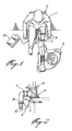
- Figure 1 is a three dimensional view of a patient, with KLE attached, being examined by a physician.
- Figure 2 is a side view of the patient.
- Figure 3 is a more detailed side view of the patient.
- Figure 4 is a front view of the leg showing motion/module digitizer attachment.
- Figure 5 is a rear view of the leg showing the electro- goniometer attachment.
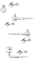
- Figure 6 is a front view of an electronic motion module/digitizer combination in accordance with the invention.
- Figure 7 is a side view of the combination.
- Figure 8 illustrates examples of inserts.
- Figure 9 is a flow chart of software for processing the electrical outputs of the combination to achieve the desired results.
- Figure 10 illustrates a dynanometer in accordance with a further aspect of the invention; and
- Figure 11 illustrates in greater detail one of the beams of the inventive dynanometer.
- Turning first to Figures 1 to 5, there is illustrated a patient 1 having a KLE attached and being examined by a
physician 3. The KLE system includes a thigh restraint means 7, an instrumented seat 9 and a motion module 11. The motion module is connected at oneend 13 to the instrumented seat which, as will be seen below, constitutes a fixed point or body. Theother end 15 is connected to a second point or body. The purpose of the instrument is to determine the movement of the second point or body relative to the first point or body in three dimensional space. - The instrumented seat may be mounted on an examining table 17 and consists of a
dynanometer 19 which measures applied forces. Instruments for measuring force are described in MEASUREMENT SYSTEMS : APPLICATION AND DESIGN by E. 0. Doebelin, McGraw Hill, pps. 333-350. The instrumented seat may also have an adjustableseat back arrangement 18 as is well known in the art. - The thigh restraint 7 comprises two or mode pairs of off-set straps, which are fastened to each other by
fastening means 8, and which displace soft tissue and may also provide a torquing of the tissue about the femur in order to minimize movement of the femur relative to the seat. - The lower leg attachment, illustrated best in Figures 4 and 5, comprises a
strap member 21, for example a velcro strap on which is carried the attachment 15a for theend 15 of the motion module. The lower leg attachment functions by referencing the motion module to three bony pro- minences of the lower leg, namely, the tibial crest 23 and the medial and lateral malleoli, 25 and 27 respectively.Rollers 29 align themselves to the bony contours of the tibial crest, and balls inmalleolar cups 31 do the same at the malleoli. These balls and rollers allow the skin to move between the attachment of the bone so that the attachment will move only with the bone which is important in attaining a true bone position measurement. - The system also includes a microprocessor based
monitor 33 which receives outputs from the dynanometer and the motion module. Thus, the KLE is capable of sensing and measuring applied loads of displacements existing during the use of all standard'knee evaluation techniques. In addition, the present KLE is designed to minimize the effects of soft tissue while still permitting the physician to hold, palpate and manipulate the joint as in normal procedures while the KLE provides accurate applied force and tibial- femoral motion readings in displayed and printed form. - The dynanometer force plate measures forces and moments in basic directions and permits the physician to know exactly to what levels the knee is being stressed. This is important when measuring laxity since the amount of relative bone motion depends on the.stress applied. Knowledge of the forces is of utmost importance to the objective interpretation of joint laxity.
- The motion module measures the true three dimensional position of the tibia relative to the seat, and hence, as the thigh is restrained, to the femur.
- The motion module is an electromechanical device which functions on the principle that-at least six measurements are required to totally define the position of an object in space as will be further discussed below. It will consist of a means capable of measuring six degrees of freedom, three dimensional motion of one point or body relative to another point or body and preferably comprises a unique arrangement of electronic components capable of measuring rotational or translational displacements. A specific module is described below in association with Figures 6 to 8. Generally speaking, the two points or bodies between which relative motions are being measured are connected by a single rigid telescopic arm, or a single arm having a joint between its two ends.
- The force measurement on the dynanometer is accomplished through the principles of opposite and equal reaction forces. The forces applied to the knee of the patient are reacted to by the femur and thigh which are in turn transmitted to the dynanometer. Inasmuch as the forces are of a different arrangement in the dynanometer as compared to the knee, knowledge of the relative position of the knee and the dynanometer, provided by the motion module, permits a theoretical interpretation of the forces and their representation in the coordinate system of the knee.
- In operation, a patient is seated in the instrumented seat and the thigh of the leg of interest is restrained as shown in Figure 1. The lower leg attachment is then mounted on the same leg as illustrated in the drawings, and the motion module is connected between the seat and the lower leg attachments. The physician can then twist the lower leg, and he will receive outputs indicating relative displacement as well as force applied.
- Turning now to Figures 6 to 8, there is illustrated a particular motion module/digitizer combination which can be used in the KLE environment. However, as also mentioned, the combination can be used in other systems or it can be used independently. For example, it could be used in association with machine tools and other mechanical systems where it is necessary to be able to measure displacement of a first point or body relative to a second point or body.
- To measure the motion of a body in three dimensional space, six unique measurements are required relating to the six degrees of freedom of motion in three dimensional space. The measurements can constitute six unique rotational measurements or six unique translational measurements or combinations thereof, i. e., four rotational and two translational, etc. The combination in accordance with the invention takes five unique measurements of rotational motion and one measurement of translational motion.
- Referring now to Figures 6 and 7, the combination includes an
elongated member 101 having afirst end 103 and asecond end 105. The elongated member comprises afirst link arm 107 and asecond link arm 109. Thelink arms - As will be obvious, other means could be used for so connecting
arms - Examples of rotary transducer means which can be used are resistive potentiometers, variable inductance transformers, syncro resolvers, inductance potentiometers and variable reluctance transducers. Examples of translational transducers which could be used are dial indicators, resistive potentiometers, variable inductance transformers, capacitance transducers, piezoelectric transducers, ionization transducers and optical transducers.
- In describing the illustrated embodiment, rotary and translational potentiometers, respectively, are utilized.
- Accordingly, these will be henceforth referred to. However, it is to be understood that such translational and rotary potentiometers could be replaced by respective ones of the above-mentioned transducers.
- Disposed at the
end 103 is a firstrotary potentiometer 113 which is disposed in line with thearm 103 and rotatable about an axis at right angles to thearm 103. A secondrotary potentiometer 115 is disposed at right angles to thepotentiometer 113 and is rotatable about an axis at right angles to the axis of thepotentiometer 113.Potentiometer 115 is mounted on mountingblock 117 for mounting the arrangement at one end thereof. - Disposed at
second end 105 is a thirdrotary potentiometer 119 which is in line with thesecond link arm 109 and which rotates about an axis at right angles to thesecond link arm 109. A fourthrotary potentiometer 121 is disposed at right angles topotentiometer 119 and is rotatable about an axis at right angles to the axis ofpotentiometer 119. A fifthrotary potentiometer 123 is also disposed at right angles topotentiometer 119 and is rotatable about an axis at right angles to the axis ofpotentiometer 119.Potentiometer 123 is also at right angles topotentiometer 121 and its axis of rotation is also at right angles to the axis ofpotentiometer 121. -
Potentiometer 123 is connected to mountingblock 25 for mounting the arrangement at a second point. - In the illustrated embodiment,
arms rotary potentiometer 127 which is in line with botharms arms - The arrangement as thus far described can measure the motion in three dimensional space of
end 105 relative to end 103 or vice-versa and is referred to as motion module. In accordance with the invention, there is provided the potential for digitizing the positions of third, fourth, fifth ... nth points or bodies (henceforth, the use of the term points will be used and understood to refer to points or bodies) in three dimensional space, or combinations thereof, and of then measuring the motion or position of one of thepoints link arm 109 is disconnectable from mountingblock 125. Specifically, the protrusion 129 which extends frompotentiometer 119 is insertable into areceptacle 131. The protrusion is also removable from the receptacle, and other inserts, such as those illustrated in Figures 8A, 8B, etc. can be inserted into the receptacle for digitizing the positions of other points in space. - For an understanding as to how the combination operates, we will take the intersection of the axes of
potentiometers potentiometers potentiometers potentiometer 127, combined with 107 and 109, provide the length of the vector R. (Knowing the length of 107 and 109, and knowing the angle therebetween, it is quite easy to determine the length of the vector R). Point B is defined as the intersection of the axes ofpotentiometers block 125 would be mounted on a moving body. Mountingblock 117 would be mounted on the fixed body or coordinate system, and the measurement of the movement of 105 relative to 103 would define the motion of the moving body relative to the fixed body or coordinate system. - The final description of the moving body motion is contained in the three finite rotations provided by the
potentiometers - To illustrate how the combination is used as a digitizer, the
protrusion 119 is removed from thereceptacle 131, and one of the digitizer tips illustrated in Figure 8 is inserted into the receptacle in place of theprotrusion 119. The tip is then pointed at points of interest, namely, a third, fourth, fifth ... nth points above-mentioned, and a reading is taken of the three dimensional.position in space of these points. - As will be understood, conductive leads from the potentiometers will be brought to a connecting board, which could be disposed on the mounting
blocks 117, so that the electrical signals developed at the potentiometers can be brought to a processing means such as the processing means illustrated schematically at 133 in Figure 1. It will, of course, be necessary to provide DC power to the potentiometer to measure the changing resistance thereof, as well known in the art, and this DC power could also be provided from the processing means 1330 - The potentiometers will provide the data for determining the extent and direction of the motion of
point 105. In order to determine the direction and extent, the data must be processed. Preferably, the data is processed by computer means. A flow chart for controlling such a computer is illustrated in Figure 8. - Three basic subroutines are employed in digitization, two of which are illustrated in the flow chart. The DIGMAT (digitization transformation matrix) and DIGIT (digitization) are shown in the flow chart while NEWTIP (support routine for user defined tip) must be provided by the user and takes into account the dimensions and shape of the user supplied tip.
- While the user must write a program employing the subroutines in a manner appropriate to his specific application, in all cases the following procedure must be used.
- The protrusion 129 is removed from the
receptacle 131, and one of a variety of tips is inserted in the receptacle. The mounting blocks 117 must be firmly mounted at a position which both permits easy access to most points of interest and is also appropriate for any subsequent motion measurement using both upper and lower components of the motion module. A position of interest is then pointed at with the tip. - The physical characteristics are inputted into the computer memory, and a code is then presented to the computer to let it know which of the tips is being used.
- Upon pointing at the position with the tip, the program must be activated either through a remote switch or a keyboard entry. The control program will then scan the signals in the potentiometer, and then in sequence, call the subroutine DIGMAT, which uses as input the voltage values of
potentiometers potentiometer 127 coordinate system. - An output is then provided of the points in the global coordinate system, that is, relative to the point 0.
- This procedure is repeated until all of the points of interest have been digitized. The TIP is then removed from the
receptacle 131 and the protrusion 129 is again inserted in the receptacle. The subroutine LOCTRN, which computes the coordinates of the digitized points in the local coordinate system (that is, with the point B as an origin) is then called. These points are then outputted to the GLOTRN subroutine which will be discussed below. - In the meantime, the mounting
block 125 would have been attached to the point of interest. Displacements of this point are performed, and the potentiometer signals are once again scanned. This data is communicated to the computer and the subroutine DISMAT is called. DISMAT computes the contents of the transformation matrix describing the body in three dimensional space. The subroutine GLOTRN is then called and outputs new positions of those points previously digitized on the body or analytically generated points, in the global system. This procedure continues as the point of interest moves through different positions. - The following are the technical specifications of the subroutines :
- This subroutine computes matrix DT12 as well as matrix DT3 which locates the position of potentiometer-113 and potentiometer-127 coordinate systems, respectively.
- These two matrices are strictly inputs to subroutines DIGIT and NEWTIP, and have no significance to the user.
- -DVOL (4), voltages of potentiometers-115, 113 and 127, and the power supply, respectively. (Note 1)
- - DT12 (3,3) and DT3 (3,3) are the above-mentioned matrices. (Note 1)
- 1-all the variable names starting with D in each subroutine, are double precision.
- This subroutine computes the coordinates of the digitizer tip with respect to the global coordinate system.
-
- -DT12 (3,3), and DT3 (3,3) locate the position of potentiometer-113 and potentiometer-127 coordinate systems, respectively. (Refer to subroutine DIGMAT). (Note 3)
- -DTIP (3) are the coordinates of the tip in use with respect to the potentiometer-127 coordinate system. (Note 1, 2 & 3)
- -DPNTRF (3) are the coordinates of the tip with respect to the global coordinate system. (Note 2 & 3)
-
- 1-The coordinates of the digitizer tips are provided as part of the Digitizer Unit. For the coordinates of User tip, use subroutine NEWTIP. (Refer to subroutine NEWTIP)
- 2-In all coordinate arrays 1, 2 & 3 are X, Y and Z coordinates, respectively. (e.g. DTIP(l) = X coordinate)
- 3-All variable names starting with D are in double precision.
- The main purpose of this subroutine is to define the coordinates of any user-designed tip with respect to potentiometer-127 coordinate system without independently measuring the tip dimensions. In order to find the tip constants, first mount tip number 1 (see 8b) and touch a point (Note 1). Then mount the new tip and touch the same point. Through the software the coordinates of the point are computed by tip #1 and are used to compute the constants for the new tip.
- (Refer to the Control Program Flow Chart).
- 1-For best results, use a point within 6 to 8 inches from the base of the digitizer.
-
- - DT12 (3,3), and DT3 (3,3) locate the position of potentiometer-113 and potentiometer-127 coordinate systems, respectively. (Note 1)
- - DPNTRF(3) : coordinates of the digitized point by tip #1 with respect to global coordinate system. (Note 1 & 2).
- - DTIP(3) : coordinates of the tip with respect to potentiometer-127 coordinate system, or better known as the new tip constants. (Note 1 & 2)
-
- 1-All variable names starting with D are double precision.
- 2-In the coordinate system arrays 1, 2 & 3 are X, Y and Z coordinates, respectively.
- DISMAT computes the position of the local coordinate system with respect to the global coordinate system. The local coordinate system is in line with indicated edges of upper mounting block.
- - DVOL(7) voltage readings of potentiometers-113, 127, 115, 119, 121, 123 and the power supply line, respectively. (Note 1)
- - DMAT2 (4,3) consists of : DMAT2 (4,1), DMAT2 (4,2) and DMAT2 (4,3) are the coordinates of point B in global coordinate system. DMAT2 (3,3) defines the position of the local coordinate system with respect to the global coordinate system. (Note 1) DMAT2 (4,3) is input only to subroutines LOCTRN and GLOTRN, and has no significance to the user.
- 1-All variable names starting with D are double precision.
- LOCTRN computes the coordinates of the digitized points in local coordinate system.
- These coordinates are constant as long as the upper mounting block is fixed to the bone or some other chosen mounting base.
- If the upper mounting block is shifted these coordinates should be computed again by calling subroutine LOCTRN. (Refer to the Control Program Flow Chart)
-
- - DMAT2 (4,3), from subroutine DISMAT (refer to subroutine DISMAT). (Note 1)
- - N is number of points; integer.
- - DPOINT (3,N) : coordinates of the digitized and analytical points in the global coordinate system. (Note 1 & 2)
- - DPNTLC (3,N) coordinates of the points with respect to the local coordinate system. (Note 1 & 2)
- 1-All variable names starting with D are double precision.
- 2-In the coordinate
arrays 1, 2 and 3 are X, Y and Z coordinates, respectively. - GLOTRN computes the new coordinates of the points in the global coordinate system.
-
- -DMAT 2 (4,3), from subroutine DISMAT (refer to subroutine DISMAT). (Note 1)
- -N number of points; integer.
- -DPNTLC (3,N) : coordinates of the points in local coordinate system. (Note 1 & 2)
- - DPNTGL (3,N) new coordinates of the points in global coordinate system. (Note 1 & 2)
-
- 1-All variable names starting with D are double precision.
- 2-In the coordinate
arrays 1, 2 and 3 are X, Y and Z coordinates, respectively. - Although reference was made to dynanometers above, in accordance with a further aspect of the invention, there is provided a novel dynanometer, comprising a triple beam support system, illustrated in Figures 10 and 11 hereof. As seen in these Figures, the dynanometer comprises a supporting
frame 201 which, in the illustrated embodiment, comprises a four walled structure. Disposed centrally of one wall is a first spherical orrectangular beam 203. Second and third rectangular orspherical beams - As seen in Figure 11, each beam comprises a
vertical support portion 209 andhorizontal deflection member 211. The vertical and horizontal members are joined by spherical/linear bearings 213. The bearings are the key to the proper operation of this triple beam system since they release all moments at the beams permitting the moments to be measured at various beams through their respective bending deflections, rather than being lost as axial beam compression or pure moments. - The beams are arranged such that the longitudinal axis of each
deflection member 211 is the perpendicular bisector of a respective side of an equilateral triangle. This particular arrangement is convenient for subsequent analyses. - Supported at the top surfaces of the vertical members is a
platform 215. The platform can be of any convenient shape, so long as it is supported by the top surfaces of the vertical members. In the illustrated embodiment, theplatform 215 forms an equilateral triangle, and a beam is disposed at each corner of the triangle. The horizontal member of the beam is perpendicular to the side of the triangle opposite its corner. - Forces are measured by their application through the
platform 215. These forces result in the deflection of the beams. The deflections are measured as an indicator of the forces. - Although in the illustrated embodiment the beams are at the corners of an equilateral triangle, any arrangement of three beams where there are no two redundant directions of deflections are permissible for two reasons :
- a) Such an arrangement will provide a rigid mechanical mechanism; and
- b) The minimum of six non-redundant forces required for the solution of the equilibrium equations will be measured.
- Devices, illustrated schematically at 217 and 219 with respect to
beam beam beam 205 are used to measure the deflection of the beams. The devices can comprise conventional displacement transducer devices and they would be mounted onto the rigid support frame and in such a manner that deflections in only the two planes of interest are measured for each beam. The resulting force measurements would be the minimum required to fully define all the external forces and moments acting on the platform. The necessary formulations for equilibrium of rigid body are the subject of numerous engineering text. - Conventional displacement transducers which can comprise the
items 217 to 227 are : - - Capacitance gauge
- - Linear variable differential transformer (LVDT)
- - Hall effect detector
- - Reflected/interrupted light intensity
- - Rectilinear potentiometer.
- With the set-up as illustrated, the deflections for each beam will be resolved in two directions through each beam. One direction is parallel to the axis of the vertical member and consists of the forces labelled F2, F4, F6, and the other direction is perpendicular to the first direction as illustrated by the arrows labelled Fl, F3 and F5. The
devices devices - When a force is applied to the
platform 215, depending on the magnitude of the force and the direction of the application thereof, thebeams devices 217 to 227. Using this technology and wellknown mathematical vector transformations, the force applied at the platform can be calculated. - Although particular embodiments have been described, this was for the purpose of illustrating but not limiting the invention. Various modifications, which.will come readily to the mind of one skilled in the art, are within the scope of the invention as defined in the appended claims.
Claims (21)
Applications Claiming Priority (2)
| Application Number | Priority Date | Filing Date | Title |
|---|---|---|---|
| US581432 | 1984-01-27 | ||
| US06/581,432 US4549555A (en) | 1984-02-17 | 1984-02-17 | Knee laxity evaluator and motion module/digitizer arrangement |
Publications (2)
| Publication Number | Publication Date |
|---|---|
| EP0155857A2 true EP0155857A2 (en) | 1985-09-25 |
| EP0155857A3 EP0155857A3 (en) | 1988-10-26 |
Family
ID=24325180
Family Applications (1)
| Application Number | Title | Priority Date | Filing Date |
|---|---|---|---|
| EP85400145A Ceased EP0155857A3 (en) | 1984-02-17 | 1985-01-29 | Knee laxity evaluator and motion module/digitizer arrangement |
Country Status (6)
| Country | Link |
|---|---|
| US (1) | US4549555A (en) |
| EP (1) | EP0155857A3 (en) |
| JP (1) | JPS60188134A (en) |
| KR (1) | KR880001186B1 (en) |
| CA (2) | CA1206048A (en) |
| IL (1) | IL74327A (en) |
Cited By (44)
| Publication number | Priority date | Publication date | Assignee | Title |
|---|---|---|---|---|
| WO1987005789A1 (en) * | 1986-03-27 | 1987-10-08 | Gregory James Roger | Measurement of laxity of anterior cruciate ligament |
| EP0244274A1 (en) * | 1986-03-31 | 1987-11-04 | Faro Medical Technologies Inc. | 3-Dimensional digitizer for skeletal analysis |
| FR2645730A1 (en) * | 1989-04-14 | 1990-10-19 | Exercice Labo Physiologie Gip | Kinetic measurement apparatus permitting the study of movement in the human being |
| FR2664489A1 (en) * | 1990-07-10 | 1992-01-17 | Mathieu Roland | Method for measuring the free internal and external rotational movements of the knee |
| EP0469966A1 (en) * | 1990-07-31 | 1992-02-05 | Faro Medical Technologies (Us) Inc. | Computer-aided surgery apparatus |
| US5251127A (en) * | 1988-02-01 | 1993-10-05 | Faro Medical Technologies Inc. | Computer-aided surgery apparatus |
| US5305203A (en) * | 1988-02-01 | 1994-04-19 | Faro Medical Technologies Inc. | Computer-aided surgery apparatus |
| FR2770992A1 (en) * | 1997-11-14 | 1999-05-21 | Als | Physical form gauge for human subject |
| US6076008A (en) | 1990-10-19 | 2000-06-13 | St. Louis University | System for indicating the position of a surgical probe within a head on an image of the head |
| US6381485B1 (en) | 1999-10-28 | 2002-04-30 | Surgical Navigation Technologies, Inc. | Registration of human anatomy integrated for electromagnetic localization |
| US6725080B2 (en) | 2000-03-01 | 2004-04-20 | Surgical Navigation Technologies, Inc. | Multiple cannula image guided tool for image guided procedures |
| DE10031887B4 (en) * | 2000-06-30 | 2008-02-07 | Stryker Leibinger Gmbh & Co. Kg | System for implantation of knee joint prostheses |
| US7998062B2 (en) | 2004-03-29 | 2011-08-16 | Superdimension, Ltd. | Endoscope structures and techniques for navigating to a target in branched structure |
| US8452068B2 (en) | 2008-06-06 | 2013-05-28 | Covidien Lp | Hybrid registration method |
| US8473032B2 (en) | 2008-06-03 | 2013-06-25 | Superdimension, Ltd. | Feature-based registration method |
| US8611984B2 (en) | 2009-04-08 | 2013-12-17 | Covidien Lp | Locatable catheter |
| US8663088B2 (en) | 2003-09-15 | 2014-03-04 | Covidien Lp | System of accessories for use with bronchoscopes |
| US8764725B2 (en) | 2004-02-09 | 2014-07-01 | Covidien Lp | Directional anchoring mechanism, method and applications thereof |
| US8838199B2 (en) | 2002-04-04 | 2014-09-16 | Medtronic Navigation, Inc. | Method and apparatus for virtual digital subtraction angiography |
| US8905920B2 (en) | 2007-09-27 | 2014-12-09 | Covidien Lp | Bronchoscope adapter and method |
| US8932207B2 (en) | 2008-07-10 | 2015-01-13 | Covidien Lp | Integrated multi-functional endoscopic tool |
| US9055881B2 (en) | 2004-04-26 | 2015-06-16 | Super Dimension Ltd. | System and method for image-based alignment of an endoscope |
| US9504530B2 (en) | 1999-10-28 | 2016-11-29 | Medtronic Navigation, Inc. | Method and apparatus for surgical navigation |
| US9575140B2 (en) | 2008-04-03 | 2017-02-21 | Covidien Lp | Magnetic interference detection system and method |
| USRE46409E1 (en) | 1997-11-20 | 2017-05-23 | Medtronic Navigation, Inc. | Image guided awl/tap/screwdriver |
| US9675424B2 (en) | 2001-06-04 | 2017-06-13 | Surgical Navigation Technologies, Inc. | Method for calibrating a navigation system |
| US9757087B2 (en) | 2002-02-28 | 2017-09-12 | Medtronic Navigation, Inc. | Method and apparatus for perspective inversion |
| US9867721B2 (en) | 2003-01-30 | 2018-01-16 | Medtronic Navigation, Inc. | Method and apparatus for post-operative tuning of a spinal implant |
| US10418705B2 (en) | 2016-10-28 | 2019-09-17 | Covidien Lp | Electromagnetic navigation antenna assembly and electromagnetic navigation system including the same |
| US10426555B2 (en) | 2015-06-03 | 2019-10-01 | Covidien Lp | Medical instrument with sensor for use in a system and method for electromagnetic navigation |
| US10446931B2 (en) | 2016-10-28 | 2019-10-15 | Covidien Lp | Electromagnetic navigation antenna assembly and electromagnetic navigation system including the same |
| US10478254B2 (en) | 2016-05-16 | 2019-11-19 | Covidien Lp | System and method to access lung tissue |
| US10517505B2 (en) | 2016-10-28 | 2019-12-31 | Covidien Lp | Systems, methods, and computer-readable media for optimizing an electromagnetic navigation system |
| US10582834B2 (en) | 2010-06-15 | 2020-03-10 | Covidien Lp | Locatable expandable working channel and method |
| US10597178B2 (en) | 2006-01-18 | 2020-03-24 | Medtronic Navigation, Inc. | Method and apparatus for providing a container to a sterile environment |
| US10615500B2 (en) | 2016-10-28 | 2020-04-07 | Covidien Lp | System and method for designing electromagnetic navigation antenna assemblies |
| US10638952B2 (en) | 2016-10-28 | 2020-05-05 | Covidien Lp | Methods, systems, and computer-readable media for calibrating an electromagnetic navigation system |
| US10722311B2 (en) | 2016-10-28 | 2020-07-28 | Covidien Lp | System and method for identifying a location and/or an orientation of an electromagnetic sensor based on a map |
| US10751126B2 (en) | 2016-10-28 | 2020-08-25 | Covidien Lp | System and method for generating a map for electromagnetic navigation |
| US10792106B2 (en) | 2016-10-28 | 2020-10-06 | Covidien Lp | System for calibrating an electromagnetic navigation system |
| US10952593B2 (en) | 2014-06-10 | 2021-03-23 | Covidien Lp | Bronchoscope adapter |
| US11006914B2 (en) | 2015-10-28 | 2021-05-18 | Medtronic Navigation, Inc. | Apparatus and method for maintaining image quality while minimizing x-ray dosage of a patient |
| US11219489B2 (en) | 2017-10-31 | 2022-01-11 | Covidien Lp | Devices and systems for providing sensors in parallel with medical tools |
| US11331150B2 (en) | 1999-10-28 | 2022-05-17 | Medtronic Navigation, Inc. | Method and apparatus for surgical navigation |
Families Citing this family (81)
| Publication number | Priority date | Publication date | Assignee | Title |
|---|---|---|---|---|
| US5269318A (en) * | 1982-08-16 | 1993-12-14 | Neurocom International Inc. | Apparatus and method for movement coordination analysis |
| US4649934A (en) * | 1985-06-07 | 1987-03-17 | Faro Medical Technologies, Inc. | Joint laxity measurement |
| US4667685A (en) * | 1985-09-23 | 1987-05-26 | Fine Edward J | Goniometric feedback device and method for monitoring angles of body joints |
| AU585710B2 (en) * | 1986-03-27 | 1989-06-22 | Mervin John Cross | Measurement of laxity of anterior cruciate ligament |
| US4742832A (en) * | 1987-02-12 | 1988-05-10 | Richard Kauffmann | Muscle measuring apparatus and method |
| US4848152A (en) * | 1987-05-04 | 1989-07-18 | Pratt Jr G Andrew | Biofeedback lifting monitor |
| US4912638A (en) * | 1987-05-04 | 1990-03-27 | Pratt Jr G Andrew | Biofeedback lifting monitor |
| US4922925A (en) * | 1988-02-29 | 1990-05-08 | Washington University | Computer based upper extremity evaluation system |
| US5099859A (en) * | 1988-12-06 | 1992-03-31 | Bell Gene D | Method and apparatus for comparative analysis of videofluoroscopic joint motion |
| US4915374A (en) * | 1989-02-02 | 1990-04-10 | Medmetric Corporation | Recumbent exercise cycle with articulated pedals |
| FR2652928B1 (en) | 1989-10-05 | 1994-07-29 | Diadix Sa | INTERACTIVE LOCAL INTERVENTION SYSTEM WITHIN A AREA OF A NON-HOMOGENEOUS STRUCTURE. |
| ATE196234T1 (en) | 1990-10-19 | 2000-09-15 | Univ St Louis | LOCALIZATION SYSTEM FOR A SURGICAL PROBE FOR USE ON THE HEAD |
| US6347240B1 (en) | 1990-10-19 | 2002-02-12 | St. Louis University | System and method for use in displaying images of a body part |
| US5040522A (en) * | 1990-11-30 | 1991-08-20 | Michael Daniels | Passive flexion chair for physical therapy |
| US5228454A (en) * | 1991-08-01 | 1993-07-20 | Drexel University | Apparatus and method for determining load-displacement and flexibility characteristics of a joint |
| US5603318A (en) | 1992-04-21 | 1997-02-18 | University Of Utah Research Foundation | Apparatus and method for photogrammetric surgical localization |
| US5263492A (en) * | 1992-04-30 | 1993-11-23 | Guy Voyce | Recording goniometer |
| ES2115776T3 (en) | 1992-08-14 | 1998-07-01 | British Telecomm | POSITION LOCATION SYSTEM. |
| US5333604A (en) * | 1992-09-16 | 1994-08-02 | Sutter Corporation | Patella exercising apparatus |
| US5348025A (en) * | 1993-02-22 | 1994-09-20 | Yale University | Apparatus and method for measuring mobility of the scaphoid |
| US5402800A (en) * | 1993-08-02 | 1995-04-04 | Hollis; J. Marcus | Ankle laxity measurement system |
| US5435321A (en) * | 1993-12-10 | 1995-07-25 | E.V.C. | Joint displacement measurement apparatus |
| US5803089A (en) | 1994-09-15 | 1998-09-08 | Visualization Technology, Inc. | Position tracking and imaging system for use in medical applications |
| US5556374A (en) * | 1994-10-04 | 1996-09-17 | Grace; Kathleen J. | Patellar alignment device |
| AU3950595A (en) | 1994-10-07 | 1996-05-06 | St. Louis University | Surgical navigation systems including reference and localization frames |
| US6978166B2 (en) | 1994-10-07 | 2005-12-20 | Saint Louis University | System for use in displaying images of a body part |
| US5662591A (en) * | 1995-05-26 | 1997-09-02 | The Johns Hopkins University | Apparatus for exercising and measuring strength of a patient's limb and an adjustable pivot clamp |
| US6167145A (en) | 1996-03-29 | 2000-12-26 | Surgical Navigation Technologies, Inc. | Bone navigation system |
| US5713821A (en) * | 1996-08-07 | 1998-02-03 | Nissen; George | Portable exercise device |
| US6226548B1 (en) | 1997-09-24 | 2001-05-01 | Surgical Navigation Technologies, Inc. | Percutaneous registration apparatus and method for use in computer-assisted surgical navigation |
| US5911695A (en) * | 1997-11-03 | 1999-06-15 | Medmetric Corporation | Shoulder tester |
| US6348058B1 (en) | 1997-12-12 | 2002-02-19 | Surgical Navigation Technologies, Inc. | Image guided spinal surgery guide, system, and method for use thereof |
| US6013039A (en) * | 1998-02-18 | 2000-01-11 | Medmetric Corporation | Patella displacement tester |
| US6118845A (en) | 1998-06-29 | 2000-09-12 | Surgical Navigation Technologies, Inc. | System and methods for the reduction and elimination of image artifacts in the calibration of X-ray imagers |
| US6477400B1 (en) | 1998-08-20 | 2002-11-05 | Sofamor Danek Holdings, Inc. | Fluoroscopic image guided orthopaedic surgery system with intraoperative registration |
| US6470207B1 (en) | 1999-03-23 | 2002-10-22 | Surgical Navigation Technologies, Inc. | Navigational guidance via computer-assisted fluoroscopic imaging |
| US6493573B1 (en) | 1999-10-28 | 2002-12-10 | Winchester Development Associates | Method and system for navigating a catheter probe in the presence of field-influencing objects |
| US8239001B2 (en) | 2003-10-17 | 2012-08-07 | Medtronic Navigation, Inc. | Method and apparatus for surgical navigation |
| US7366562B2 (en) | 2003-10-17 | 2008-04-29 | Medtronic Navigation, Inc. | Method and apparatus for surgical navigation |
| US6235038B1 (en) | 1999-10-28 | 2001-05-22 | Medtronic Surgical Navigation Technologies | System for translation of electromagnetic and optical localization systems |
| US6499488B1 (en) | 1999-10-28 | 2002-12-31 | Winchester Development Associates | Surgical sensor |
| US6474341B1 (en) | 1999-10-28 | 2002-11-05 | Surgical Navigation Technologies, Inc. | Surgical communication and power system |
| US6535756B1 (en) | 2000-04-07 | 2003-03-18 | Surgical Navigation Technologies, Inc. | Trajectory storage apparatus and method for surgical navigation system |
| US7085400B1 (en) | 2000-06-14 | 2006-08-01 | Surgical Navigation Technologies, Inc. | System and method for image based sensor calibration |
| US6948502B2 (en) | 2002-05-09 | 2005-09-27 | Mayo Foundation For Medical Education And Research | Method and apparatus for positioning a forearm for imaging and analysis |
| US7697972B2 (en) | 2002-11-19 | 2010-04-13 | Medtronic Navigation, Inc. | Navigation system for cardiac therapies |
| US7599730B2 (en) | 2002-11-19 | 2009-10-06 | Medtronic Navigation, Inc. | Navigation system for cardiac therapies |
| US6966882B2 (en) * | 2002-11-25 | 2005-11-22 | Tibion Corporation | Active muscle assistance device and method |
| US7542791B2 (en) | 2003-01-30 | 2009-06-02 | Medtronic Navigation, Inc. | Method and apparatus for preplanning a surgical procedure |
| US20040260208A1 (en) * | 2003-06-20 | 2004-12-23 | Robert Laprade | Knee laxity measurement |
| US7179234B2 (en) * | 2003-07-10 | 2007-02-20 | Neurocom International, Inc. | Apparatus and method for characterizing contributions of forces associated with a body part of a subject |
| US7313430B2 (en) | 2003-08-28 | 2007-12-25 | Medtronic Navigation, Inc. | Method and apparatus for performing stereotactic surgery |
| US7835778B2 (en) | 2003-10-16 | 2010-11-16 | Medtronic Navigation, Inc. | Method and apparatus for surgical navigation of a multiple piece construct for implantation |
| US7840253B2 (en) | 2003-10-17 | 2010-11-23 | Medtronic Navigation, Inc. | Method and apparatus for surgical navigation |
| US7567834B2 (en) | 2004-05-03 | 2009-07-28 | Medtronic Navigation, Inc. | Method and apparatus for implantation between two vertebral bodies |
| US7771319B1 (en) | 2004-05-10 | 2010-08-10 | Michael G. Lannon | Exercising apparatus |
| US20180008865A9 (en) | 2004-05-10 | 2018-01-11 | Koko Fitness, Inc. | Exercising apparatus |
| US8105207B1 (en) | 2004-05-10 | 2012-01-31 | Michael G. Lannon | Exercising apparatus |
| US7835784B2 (en) | 2005-09-21 | 2010-11-16 | Medtronic Navigation, Inc. | Method and apparatus for positioning a reference frame |
| US7811189B2 (en) | 2005-12-30 | 2010-10-12 | Tibion Corporation | Deflector assembly |
| US8112292B2 (en) | 2006-04-21 | 2012-02-07 | Medtronic Navigation, Inc. | Method and apparatus for optimizing a therapy |
| US8660635B2 (en) | 2006-09-29 | 2014-02-25 | Medtronic, Inc. | Method and apparatus for optimizing a computer assisted surgical procedure |
| US8353854B2 (en) | 2007-02-14 | 2013-01-15 | Tibion Corporation | Method and devices for moving a body joint |
| US7543511B2 (en) * | 2007-07-27 | 2009-06-09 | Align Technology Inc. | Concurrently measuring a force exerted upon each of a plurality of teeth |
| US8265949B2 (en) * | 2007-09-27 | 2012-09-11 | Depuy Products, Inc. | Customized patient surgical plan |
| EP2957244B1 (en) | 2007-09-30 | 2020-04-15 | DePuy Products, Inc. | Method of generating a customized patient-specific orthopaedic surgical instrumentation |
| US8357111B2 (en) * | 2007-09-30 | 2013-01-22 | Depuy Products, Inc. | Method and system for designing patient-specific orthopaedic surgical instruments |
| CA2706728A1 (en) * | 2007-11-26 | 2009-06-04 | Ecole De Technologie Superieure | Harness system for kinematic analysis of the knee |
| US8052629B2 (en) | 2008-02-08 | 2011-11-08 | Tibion Corporation | Multi-fit orthotic and mobility assistance apparatus |
| US20090306548A1 (en) | 2008-06-05 | 2009-12-10 | Bhugra Kern S | Therapeutic method and device for rehabilitation |
| US8058823B2 (en) | 2008-08-14 | 2011-11-15 | Tibion Corporation | Actuator system with a multi-motor assembly for extending and flexing a joint |
| US8274244B2 (en) | 2008-08-14 | 2012-09-25 | Tibion Corporation | Actuator system and method for extending a joint |
| US8165658B2 (en) | 2008-09-26 | 2012-04-24 | Medtronic, Inc. | Method and apparatus for positioning a guide relative to a base |
| KR200450657Y1 (en) * | 2008-10-10 | 2010-10-20 | 박휘영 | knee joint relaxation measurement chair |
| US8175681B2 (en) | 2008-12-16 | 2012-05-08 | Medtronic Navigation Inc. | Combination of electromagnetic and electropotential localization |
| US20100185202A1 (en) * | 2009-01-16 | 2010-07-22 | Lester Mark B | Customized patient-specific patella resectioning guide |
| US8639455B2 (en) | 2009-02-09 | 2014-01-28 | Alterg, Inc. | Foot pad device and method of obtaining weight data |
| US8494614B2 (en) | 2009-08-31 | 2013-07-23 | Regents Of The University Of Minnesota | Combination localization system |
| US8494613B2 (en) | 2009-08-31 | 2013-07-23 | Medtronic, Inc. | Combination localization system |
| WO2014151584A1 (en) | 2013-03-15 | 2014-09-25 | Alterg, Inc. | Orthotic device drive system and method |
| US11051829B2 (en) | 2018-06-26 | 2021-07-06 | DePuy Synthes Products, Inc. | Customized patient-specific orthopaedic surgical instrument |
Citations (13)
| Publication number | Priority date | Publication date | Assignee | Title |
|---|---|---|---|---|
| US3020639A (en) * | 1960-10-14 | 1962-02-13 | Peter V Karpovich | Method and apparatus for measuring angles of body joints |
| US3037286A (en) * | 1957-01-28 | 1962-06-05 | North American Aviation Inc | Vector gage |
| US3944798A (en) * | 1974-04-18 | 1976-03-16 | Eaton-Leonard Corporation | Method and apparatus for measuring direction |
| EP0001686A1 (en) * | 1977-10-20 | 1979-05-02 | Imperial Chemical Industries Plc | An industrial manipulator for placing articles in close proximity to adjacent articles and a method of close packing articles therewith |
| GB2008287A (en) * | 1977-11-21 | 1979-05-31 | Fmc Corp | Apparatus for sensing the position of an articulated arm |
| US4161874A (en) * | 1978-08-08 | 1979-07-24 | The United States Of America As Represented By The Secretary Of The Air Force | Head and neck impact measurement system |
| EP0016668A1 (en) * | 1979-03-22 | 1980-10-01 | Regie Nationale Des Usines Renault | Six-axes manipulator |
| US4306571A (en) * | 1980-03-31 | 1981-12-22 | Orthopaedic Research Institute, Inc. | Dynamic joint motion analysis technique |
| US4331954A (en) * | 1980-10-10 | 1982-05-25 | Bauman Verne W | Planar coordinate resolving system |
| US4436099A (en) * | 1981-08-14 | 1984-03-13 | The University Of Toledo | Instrument for measuring the range of motion associated with a human body joint |
| US4477973A (en) * | 1982-07-14 | 1984-10-23 | Micro Control Systems, Inc. | Three dimensional graphics tablet |
| EP0132163A1 (en) * | 1983-05-06 | 1985-01-23 | HISPANO-SUIZA Société anonyme dite: | Sensor for measuring force and moment components equivalent to an applied force system |
| JPS6098325A (en) * | 1983-11-02 | 1985-06-01 | Sumitomo Electric Ind Ltd | Force sensing sensor |
Family Cites Families (3)
| Publication number | Priority date | Publication date | Assignee | Title |
|---|---|---|---|---|
| US3258007A (en) * | 1963-07-19 | 1966-06-28 | Peter V Karpovich | Rotary electrogoniometer for measuring degree of rotation of the forearm |
| SU733653A1 (en) * | 1978-02-08 | 1980-05-15 | Войсковая Часть 63559 | Apparatus for registrating angular parameters of operator's posture |
| SU719609A1 (en) * | 1978-06-12 | 1980-03-05 | Коми филиал АН СССР | Device for studying muscular activity in animals |
-
1984
- 1984-02-17 US US06/581,432 patent/US4549555A/en not_active Expired - Fee Related
- 1984-12-12 CA CA000469958A patent/CA1206048A/en not_active Expired
-
1985
- 1985-01-28 KR KR1019850000515A patent/KR880001186B1/en not_active IP Right Cessation
- 1985-01-29 EP EP85400145A patent/EP0155857A3/en not_active Ceased
- 1985-02-13 IL IL74327A patent/IL74327A/en unknown
- 1985-02-18 JP JP60030150A patent/JPS60188134A/en active Granted
- 1985-09-26 CA CA000491613A patent/CA1210251A/en not_active Expired
Patent Citations (14)
| Publication number | Priority date | Publication date | Assignee | Title |
|---|---|---|---|---|
| US3037286A (en) * | 1957-01-28 | 1962-06-05 | North American Aviation Inc | Vector gage |
| US3020639A (en) * | 1960-10-14 | 1962-02-13 | Peter V Karpovich | Method and apparatus for measuring angles of body joints |
| US3944798A (en) * | 1974-04-18 | 1976-03-16 | Eaton-Leonard Corporation | Method and apparatus for measuring direction |
| EP0001686A1 (en) * | 1977-10-20 | 1979-05-02 | Imperial Chemical Industries Plc | An industrial manipulator for placing articles in close proximity to adjacent articles and a method of close packing articles therewith |
| US4205308A (en) * | 1977-11-21 | 1980-05-27 | Fmc Corporation | Programmable alarm system for marine loading arms |
| GB2008287A (en) * | 1977-11-21 | 1979-05-31 | Fmc Corp | Apparatus for sensing the position of an articulated arm |
| US4161874A (en) * | 1978-08-08 | 1979-07-24 | The United States Of America As Represented By The Secretary Of The Air Force | Head and neck impact measurement system |
| EP0016668A1 (en) * | 1979-03-22 | 1980-10-01 | Regie Nationale Des Usines Renault | Six-axes manipulator |
| US4306571A (en) * | 1980-03-31 | 1981-12-22 | Orthopaedic Research Institute, Inc. | Dynamic joint motion analysis technique |
| US4331954A (en) * | 1980-10-10 | 1982-05-25 | Bauman Verne W | Planar coordinate resolving system |
| US4436099A (en) * | 1981-08-14 | 1984-03-13 | The University Of Toledo | Instrument for measuring the range of motion associated with a human body joint |
| US4477973A (en) * | 1982-07-14 | 1984-10-23 | Micro Control Systems, Inc. | Three dimensional graphics tablet |
| EP0132163A1 (en) * | 1983-05-06 | 1985-01-23 | HISPANO-SUIZA Société anonyme dite: | Sensor for measuring force and moment components equivalent to an applied force system |
| JPS6098325A (en) * | 1983-11-02 | 1985-06-01 | Sumitomo Electric Ind Ltd | Force sensing sensor |
Non-Patent Citations (3)
| Title |
|---|
| ISA TRANSACTIONS, vol. 17, no. 1, 1978, pages 13-19, E.Y.S. CHAO et al.: "Instrumented measurement of human joint motion". * |
| MEDICAL & BIOLOGICAL ENGINEERING AND COMPUTING, vol. 15, no. 5, September 1977, pages 548-552; P.J. LOWE et al.: "Knee analyser: An objective method of evaluating mediolateral stability in the knee". * |
| PATENT ABSTRACTS OF JAPAN, vol. 9, no. 246 (P-393)(1969) 3 October 1985; & JP-A-60 098 325 (SUMITOMO DENKI KOGYO K.K.) 01-06-1985 * |
Cited By (83)
| Publication number | Priority date | Publication date | Assignee | Title |
|---|---|---|---|---|
| US4913163A (en) * | 1986-03-27 | 1990-04-03 | Roger Gregory J | Measurement of laxity of anterior cruciate ligament |
| WO1987005789A1 (en) * | 1986-03-27 | 1987-10-08 | Gregory James Roger | Measurement of laxity of anterior cruciate ligament |
| EP0244274A1 (en) * | 1986-03-31 | 1987-11-04 | Faro Medical Technologies Inc. | 3-Dimensional digitizer for skeletal analysis |
| US5251127A (en) * | 1988-02-01 | 1993-10-05 | Faro Medical Technologies Inc. | Computer-aided surgery apparatus |
| US5748767A (en) * | 1988-02-01 | 1998-05-05 | Faro Technology, Inc. | Computer-aided surgery apparatus |
| US5305203A (en) * | 1988-02-01 | 1994-04-19 | Faro Medical Technologies Inc. | Computer-aided surgery apparatus |
| FR2645730A1 (en) * | 1989-04-14 | 1990-10-19 | Exercice Labo Physiologie Gip | Kinetic measurement apparatus permitting the study of movement in the human being |
| FR2664489A1 (en) * | 1990-07-10 | 1992-01-17 | Mathieu Roland | Method for measuring the free internal and external rotational movements of the knee |
| EP0469966A1 (en) * | 1990-07-31 | 1992-02-05 | Faro Medical Technologies (Us) Inc. | Computer-aided surgery apparatus |
| US6076008A (en) | 1990-10-19 | 2000-06-13 | St. Louis University | System for indicating the position of a surgical probe within a head on an image of the head |
| FR2770992A1 (en) * | 1997-11-14 | 1999-05-21 | Als | Physical form gauge for human subject |
| USRE46422E1 (en) | 1997-11-20 | 2017-06-06 | Medtronic Navigation, Inc. | Image guided awl/tap/screwdriver |
| USRE46409E1 (en) | 1997-11-20 | 2017-05-23 | Medtronic Navigation, Inc. | Image guided awl/tap/screwdriver |
| US11331150B2 (en) | 1999-10-28 | 2022-05-17 | Medtronic Navigation, Inc. | Method and apparatus for surgical navigation |
| US6381485B1 (en) | 1999-10-28 | 2002-04-30 | Surgical Navigation Technologies, Inc. | Registration of human anatomy integrated for electromagnetic localization |
| US9504530B2 (en) | 1999-10-28 | 2016-11-29 | Medtronic Navigation, Inc. | Method and apparatus for surgical navigation |
| US7657300B2 (en) | 1999-10-28 | 2010-02-02 | Medtronic Navigation, Inc. | Registration of human anatomy integrated for electromagnetic localization |
| US6725080B2 (en) | 2000-03-01 | 2004-04-20 | Surgical Navigation Technologies, Inc. | Multiple cannula image guided tool for image guided procedures |
| US10898153B2 (en) | 2000-03-01 | 2021-01-26 | Medtronic Navigation, Inc. | Multiple cannula image guided tool for image guided procedures |
| DE10031887B4 (en) * | 2000-06-30 | 2008-02-07 | Stryker Leibinger Gmbh & Co. Kg | System for implantation of knee joint prostheses |
| US9675424B2 (en) | 2001-06-04 | 2017-06-13 | Surgical Navigation Technologies, Inc. | Method for calibrating a navigation system |
| US9757087B2 (en) | 2002-02-28 | 2017-09-12 | Medtronic Navigation, Inc. | Method and apparatus for perspective inversion |
| US8838199B2 (en) | 2002-04-04 | 2014-09-16 | Medtronic Navigation, Inc. | Method and apparatus for virtual digital subtraction angiography |
| US10743748B2 (en) | 2002-04-17 | 2020-08-18 | Covidien Lp | Endoscope structures and techniques for navigating to a target in branched structure |
| US8696548B2 (en) | 2002-04-17 | 2014-04-15 | Covidien Lp | Endoscope structures and techniques for navigating to a target in branched structure |
| US9642514B2 (en) | 2002-04-17 | 2017-05-09 | Covidien Lp | Endoscope structures and techniques for navigating to a target in a branched structure |
| US9867721B2 (en) | 2003-01-30 | 2018-01-16 | Medtronic Navigation, Inc. | Method and apparatus for post-operative tuning of a spinal implant |
| US11684491B2 (en) | 2003-01-30 | 2023-06-27 | Medtronic Navigation, Inc. | Method and apparatus for post-operative tuning of a spinal implant |
| US11707363B2 (en) | 2003-01-30 | 2023-07-25 | Medtronic Navigation, Inc. | Method and apparatus for post-operative tuning of a spinal implant |
| US9089261B2 (en) | 2003-09-15 | 2015-07-28 | Covidien Lp | System of accessories for use with bronchoscopes |
| US10383509B2 (en) | 2003-09-15 | 2019-08-20 | Covidien Lp | System of accessories for use with bronchoscopes |
| US8663088B2 (en) | 2003-09-15 | 2014-03-04 | Covidien Lp | System of accessories for use with bronchoscopes |
| US8764725B2 (en) | 2004-02-09 | 2014-07-01 | Covidien Lp | Directional anchoring mechanism, method and applications thereof |
| US7998062B2 (en) | 2004-03-29 | 2011-08-16 | Superdimension, Ltd. | Endoscope structures and techniques for navigating to a target in branched structure |
| US10321803B2 (en) | 2004-04-26 | 2019-06-18 | Covidien Lp | System and method for image-based alignment of an endoscope |
| US9055881B2 (en) | 2004-04-26 | 2015-06-16 | Super Dimension Ltd. | System and method for image-based alignment of an endoscope |
| US10597178B2 (en) | 2006-01-18 | 2020-03-24 | Medtronic Navigation, Inc. | Method and apparatus for providing a container to a sterile environment |
| US9986895B2 (en) | 2007-09-27 | 2018-06-05 | Covidien Lp | Bronchoscope adapter and method |
| US10390686B2 (en) | 2007-09-27 | 2019-08-27 | Covidien Lp | Bronchoscope adapter and method |
| US8905920B2 (en) | 2007-09-27 | 2014-12-09 | Covidien Lp | Bronchoscope adapter and method |
| US10980400B2 (en) | 2007-09-27 | 2021-04-20 | Covidien Lp | Bronchoscope adapter and method |
| US9668639B2 (en) | 2007-09-27 | 2017-06-06 | Covidien Lp | Bronchoscope adapter and method |
| US9575140B2 (en) | 2008-04-03 | 2017-02-21 | Covidien Lp | Magnetic interference detection system and method |
| US10096126B2 (en) | 2008-06-03 | 2018-10-09 | Covidien Lp | Feature-based registration method |
| US11783498B2 (en) | 2008-06-03 | 2023-10-10 | Covidien Lp | Feature-based registration method |
| US8473032B2 (en) | 2008-06-03 | 2013-06-25 | Superdimension, Ltd. | Feature-based registration method |
| US11074702B2 (en) | 2008-06-03 | 2021-07-27 | Covidien Lp | Feature-based registration method |
| US9659374B2 (en) | 2008-06-03 | 2017-05-23 | Covidien Lp | Feature-based registration method |
| US10285623B2 (en) | 2008-06-06 | 2019-05-14 | Covidien Lp | Hybrid registration method |
| US9271803B2 (en) | 2008-06-06 | 2016-03-01 | Covidien Lp | Hybrid registration method |
| US8452068B2 (en) | 2008-06-06 | 2013-05-28 | Covidien Lp | Hybrid registration method |
| US8467589B2 (en) | 2008-06-06 | 2013-06-18 | Covidien Lp | Hybrid registration method |
| US10674936B2 (en) | 2008-06-06 | 2020-06-09 | Covidien Lp | Hybrid registration method |
| US10478092B2 (en) | 2008-06-06 | 2019-11-19 | Covidien Lp | Hybrid registration method |
| US11931141B2 (en) | 2008-06-06 | 2024-03-19 | Covidien Lp | Hybrid registration method |
| US11234611B2 (en) | 2008-07-10 | 2022-02-01 | Covidien Lp | Integrated multi-functional endoscopic tool |
| US10912487B2 (en) | 2008-07-10 | 2021-02-09 | Covidien Lp | Integrated multi-function endoscopic tool |
| US10070801B2 (en) | 2008-07-10 | 2018-09-11 | Covidien Lp | Integrated multi-functional endoscopic tool |
| US8932207B2 (en) | 2008-07-10 | 2015-01-13 | Covidien Lp | Integrated multi-functional endoscopic tool |
| US11241164B2 (en) | 2008-07-10 | 2022-02-08 | Covidien Lp | Integrated multi-functional endoscopic tool |
| US9113813B2 (en) | 2009-04-08 | 2015-08-25 | Covidien Lp | Locatable catheter |
| US10154798B2 (en) | 2009-04-08 | 2018-12-18 | Covidien Lp | Locatable catheter |
| US8611984B2 (en) | 2009-04-08 | 2013-12-17 | Covidien Lp | Locatable catheter |
| US10582834B2 (en) | 2010-06-15 | 2020-03-10 | Covidien Lp | Locatable expandable working channel and method |
| US10952593B2 (en) | 2014-06-10 | 2021-03-23 | Covidien Lp | Bronchoscope adapter |
| US10426555B2 (en) | 2015-06-03 | 2019-10-01 | Covidien Lp | Medical instrument with sensor for use in a system and method for electromagnetic navigation |
| US11801024B2 (en) | 2015-10-28 | 2023-10-31 | Medtronic Navigation, Inc. | Apparatus and method for maintaining image quality while minimizing x-ray dosage of a patient |
| US11006914B2 (en) | 2015-10-28 | 2021-05-18 | Medtronic Navigation, Inc. | Apparatus and method for maintaining image quality while minimizing x-ray dosage of a patient |
| US11786317B2 (en) | 2016-05-16 | 2023-10-17 | Covidien Lp | System and method to access lung tissue |
| US10478254B2 (en) | 2016-05-16 | 2019-11-19 | Covidien Lp | System and method to access lung tissue |
| US11160617B2 (en) | 2016-05-16 | 2021-11-02 | Covidien Lp | System and method to access lung tissue |
| US10792106B2 (en) | 2016-10-28 | 2020-10-06 | Covidien Lp | System for calibrating an electromagnetic navigation system |
| US10446931B2 (en) | 2016-10-28 | 2019-10-15 | Covidien Lp | Electromagnetic navigation antenna assembly and electromagnetic navigation system including the same |
| US11672604B2 (en) | 2016-10-28 | 2023-06-13 | Covidien Lp | System and method for generating a map for electromagnetic navigation |
| US10418705B2 (en) | 2016-10-28 | 2019-09-17 | Covidien Lp | Electromagnetic navigation antenna assembly and electromagnetic navigation system including the same |
| US10517505B2 (en) | 2016-10-28 | 2019-12-31 | Covidien Lp | Systems, methods, and computer-readable media for optimizing an electromagnetic navigation system |
| US11759264B2 (en) | 2016-10-28 | 2023-09-19 | Covidien Lp | System and method for identifying a location and/or an orientation of an electromagnetic sensor based on a map |
| US10615500B2 (en) | 2016-10-28 | 2020-04-07 | Covidien Lp | System and method for designing electromagnetic navigation antenna assemblies |
| US10751126B2 (en) | 2016-10-28 | 2020-08-25 | Covidien Lp | System and method for generating a map for electromagnetic navigation |
| US11786314B2 (en) | 2016-10-28 | 2023-10-17 | Covidien Lp | System for calibrating an electromagnetic navigation system |
| US10722311B2 (en) | 2016-10-28 | 2020-07-28 | Covidien Lp | System and method for identifying a location and/or an orientation of an electromagnetic sensor based on a map |
| US10638952B2 (en) | 2016-10-28 | 2020-05-05 | Covidien Lp | Methods, systems, and computer-readable media for calibrating an electromagnetic navigation system |
| US11219489B2 (en) | 2017-10-31 | 2022-01-11 | Covidien Lp | Devices and systems for providing sensors in parallel with medical tools |
Also Published As
| Publication number | Publication date |
|---|---|
| IL74327A (en) | 1991-06-30 |
| JPS60188134A (en) | 1985-09-25 |
| EP0155857A3 (en) | 1988-10-26 |
| CA1210251A (en) | 1986-08-26 |
| KR850005769A (en) | 1985-09-26 |
| US4549555A (en) | 1985-10-29 |
| KR880001186B1 (en) | 1988-07-02 |
| CA1206048A (en) | 1986-06-17 |
| IL74327A0 (en) | 1985-05-31 |
| JPH0449420B2 (en) | 1992-08-11 |
Similar Documents
| Publication | Publication Date | Title |
|---|---|---|
| US4571834A (en) | Knee laxity evaluator and motion module/digitizer arrangement | |
| US4549555A (en) | Knee laxity evaluator and motion module/digitizer arrangement | |
| PANJABI et al. | An analysis of errors in kinematic parameters associated with in vivo functional radiographs | |
| US4922925A (en) | Computer based upper extremity evaluation system | |
| EP0204639B1 (en) | Joint laxity measurement | |
| US5408754A (en) | Method and apparatus for measuring sleeping positions | |
| US5313968A (en) | Joint range of motion analyzer using euler angle | |
| US6524260B2 (en) | Contour mapping system and method particularly useful as a spine analyzer and probe therefor | |
| Legnani et al. | A model of an electro-goniometer and its calibration for biomechanical applications | |
| US6059784A (en) | Capacitive extensometer particularly suited for measuring in vivo bone strain | |
| US5082001A (en) | Enhanced computer based upper extremity evaluation system | |
| Kaigle et al. | A method for the intravital measurement of interspinous kinematics | |
| Kaleps et al. | Measurement of Hybrid III dummy properties and analytical simulation data base development | |
| Erdman et al. | Kinematic and kinetic analysis of the human wrist by stereoscopic instrumentation | |
| Rohling et al. | Calibrating the human hand for haptic interfaces | |
| US4667520A (en) | Dynamometer arrangement | |
| Mooring et al. | Aspects of robot repeatability | |
| Engin et al. | Kinematic and force data collection in biomechanics by means of sonic emitters—I: Kinematic data collection methodology | |
| CA1208091A (en) | Knee laxity evaluator and motion module/digitizer arrangement | |
| KR880001185B1 (en) | Inspection apparatus on the knee laxity evaluator | |
| Gilad et al. | A technique for assessment of torso kinesiology | |
| Thurston | Repeatability studies of a television/computer system for measuring spinal and pelvic movements | |
| KR880001184B1 (en) | Arrangement of motion module and digitizer | |
| US6450027B1 (en) | Device for determining a strength profile of a human limb | |
| Runciman et al. | Strain gauged six-component load transducer for use in upper limb biomechanics |
Legal Events
| Date | Code | Title | Description |
|---|---|---|---|
| PUAI | Public reference made under article 153(3) epc to a published international application that has entered the european phase |
Free format text: ORIGINAL CODE: 0009012 |
|
| AK | Designated contracting states |
Designated state(s): AT BE CH DE FR GB IT LI LU NL SE |
|
| RAP1 | Party data changed (applicant data changed or rights of an application transferred) |
Owner name: FARO MEDICAL TECHNOLOGIES INC. |
|
| PUAL | Search report despatched |
Free format text: ORIGINAL CODE: 0009013 |
|
| AK | Designated contracting states |
Kind code of ref document: A3 Designated state(s): AT BE CH DE FR GB IT LI LU NL SE |
|
| 17P | Request for examination filed |
Effective date: 19890418 |
|
| 17Q | First examination report despatched |
Effective date: 19891212 |
|
| STAA | Information on the status of an ep patent application or granted ep patent |
Free format text: STATUS: THE APPLICATION HAS BEEN REFUSED |
|
| 18R | Application refused |
Effective date: 19910624 |
|
| RIN1 | Information on inventor provided before grant (corrected) |
Inventor name: RAAB, SIMON Inventor name: FRASER, GREGORY A. |