EP0160942A2 - Elliptical cross-section slotted-tube radio-frequency resonator for nuclear magnetic resonance imaging - Google Patents
Elliptical cross-section slotted-tube radio-frequency resonator for nuclear magnetic resonance imaging Download PDFInfo
- Publication number
- EP0160942A2 EP0160942A2 EP85105377A EP85105377A EP0160942A2 EP 0160942 A2 EP0160942 A2 EP 0160942A2 EP 85105377 A EP85105377 A EP 85105377A EP 85105377 A EP85105377 A EP 85105377A EP 0160942 A2 EP0160942 A2 EP 0160942A2
- Authority
- EP
- European Patent Office
- Prior art keywords
- resonator
- portions
- outer structure
- wing
- elliptical cross
- Prior art date
- Legal status (The legal status is an assumption and is not a legal conclusion. Google has not performed a legal analysis and makes no representation as to the accuracy of the status listed.)
- Ceased
Links
Images
Classifications
-
- G—PHYSICS
- G01—MEASURING; TESTING
- G01R—MEASURING ELECTRIC VARIABLES; MEASURING MAGNETIC VARIABLES
- G01R33/00—Arrangements or instruments for measuring magnetic variables
- G01R33/20—Arrangements or instruments for measuring magnetic variables involving magnetic resonance
-
- G—PHYSICS
- G01—MEASURING; TESTING
- G01R—MEASURING ELECTRIC VARIABLES; MEASURING MAGNETIC VARIABLES
- G01R33/00—Arrangements or instruments for measuring magnetic variables
- G01R33/20—Arrangements or instruments for measuring magnetic variables involving magnetic resonance
- G01R33/28—Details of apparatus provided for in groups G01R33/44 - G01R33/64
- G01R33/32—Excitation or detection systems, e.g. using radio frequency signals
- G01R33/34—Constructional details, e.g. resonators, specially adapted to MR
- G01R33/345—Constructional details, e.g. resonators, specially adapted to MR of waveguide type
-
- A—HUMAN NECESSITIES
- A61—MEDICAL OR VETERINARY SCIENCE; HYGIENE
- A61B—DIAGNOSIS; SURGERY; IDENTIFICATION
- A61B6/00—Apparatus for radiation diagnosis, e.g. combined with radiation therapy equipment
-
- G—PHYSICS
- G01—MEASURING; TESTING
- G01R—MEASURING ELECTRIC VARIABLES; MEASURING MAGNETIC VARIABLES
- G01R33/00—Arrangements or instruments for measuring magnetic variables
- G01R33/20—Arrangements or instruments for measuring magnetic variables involving magnetic resonance
- G01R33/28—Details of apparatus provided for in groups G01R33/44 - G01R33/64
- G01R33/32—Excitation or detection systems, e.g. using radio frequency signals
- G01R33/34—Constructional details, e.g. resonators, specially adapted to MR
- G01R33/343—Constructional details, e.g. resonators, specially adapted to MR of slotted-tube or loop-gap type
-
- G—PHYSICS
- G01—MEASURING; TESTING
- G01R—MEASURING ELECTRIC VARIABLES; MEASURING MAGNETIC VARIABLES
- G01R33/00—Arrangements or instruments for measuring magnetic variables
- G01R33/20—Arrangements or instruments for measuring magnetic variables involving magnetic resonance
- G01R33/28—Details of apparatus provided for in groups G01R33/44 - G01R33/64
- G01R33/32—Excitation or detection systems, e.g. using radio frequency signals
- G01R33/36—Electrical details, e.g. matching or coupling of the coil to the receiver
- G01R33/3628—Tuning/matching of the transmit/receive coil
-
- Y—GENERAL TAGGING OF NEW TECHNOLOGICAL DEVELOPMENTS; GENERAL TAGGING OF CROSS-SECTIONAL TECHNOLOGIES SPANNING OVER SEVERAL SECTIONS OF THE IPC; TECHNICAL SUBJECTS COVERED BY FORMER USPC CROSS-REFERENCE ART COLLECTIONS [XRACs] AND DIGESTS
- Y10—TECHNICAL SUBJECTS COVERED BY FORMER USPC
- Y10S—TECHNICAL SUBJECTS COVERED BY FORMER USPC CROSS-REFERENCE ART COLLECTIONS [XRACs] AND DIGESTS
- Y10S505/00—Superconductor technology: apparatus, material, process
- Y10S505/825—Apparatus per se, device per se, or process of making or operating same
- Y10S505/842—Measuring and testing
- Y10S505/843—Electrical
- Y10S505/844—Nuclear magnetic resonance, NMR, system or device
Definitions
- the present application relates to nuclear magnetic resonance (NMR) imaging and, more particularly, to a novel slotted-tube radio-frequency (RF) resonator having an ellip-tical cross-section, for use in obtaining NMR images in a NMR imaging system.
- NMR nuclear magnetic resonance
- RF radio-frequency
- a slotted-tube resonator has been used at an even higher frequency of 300 MHz., for small-sample 1 H NMR analysis, but this resonator (described by D. Alderman et al., in "An Efficient Decoupler Coil Design which Reduces Heating in Conductive Samples in Safer Conducting Spectrometers", Volume 36, J. of Mag. Resonance, pp. 447-451, 1979), has such a small working volume diameter (e.g. about .72”) as to preclude access of the human head, extremities and/or torso therein for imaging purposes.
- a small working volume diameter e.g. about .72
- the coil loss noise-inducing term (aR c 2 F 1 ⁇ 2 ) can be considered optimal when its noise contribution is insignificant compared to the inductive losses in the body sample being imaged.
- the observed losses in the imaged object e.g. the patient's head, were only about 0.4 times the coil losses.
- the coil noise contribution in this experiment is not insignificant compared to the body loss contribution and coil noise cannot be considered optimized.
- a radio-frequency coil for NMR imaging which will not only be capable of operation at the Larmor frequencies (between about 20 MHz. to about 100 MHz.) associated with static magnetic fields of magnitude greater than about 0.5 Tesla, but will also have a relatively insignificant loss contribution compared to the losses introduced by the object being imaged.
- the ratio of the RF coil quality Q factor measured with the NMR coil substantially filled or loaded by the body (Q L ) can be compared to the Q factor measured with the coil empty or unloaded (Q u ) and is a measure of the relative noise contribution from the RF coil. Therefore, a high Q U/QL ratio is most desirable to optimize the signal-to-noise ratio for NMR imaging.
- a radio-frequency coil for nuclear magnetic resonance imaging at Larmor frequencies associated with.a static magnetic field of magnitude greater than about 0.5 Tesla, comprises a slotted-tube radio-frequency resonator having an elliptical cross-section.
- the resonator contains first and second complementary outer structure portions having relatively wide bands connecting juxtaposed wing structures, with the end of each of the four wings (leftwardly and rightwardly arranged respectively at the top and bottom of each outer structure portion band) being spaced from a complementary one of the wing portions of the other outer structure portion band and capacitively coupled thereto.
- An inner guard structure utilizes a pair of elliptical rings placed substantially in registration with the elliptical portions of the outer structure formed by the capacitively-coupled juxtaposed upper or lower wing portions.
- the resonator wings and band portions define a pair of complementary windows, which may be placed upon either the regions of greatest or least curvature of the elliptical cross-sectioned resonator.
- One of the guard rings is directly connected to system common potential while radio-frequency energy is coupled to one of the complementary outer section portions at an edge substantially at the midpoint of a band portion thereof.
- the eccentricity ratio of the elliptical cross-section of the resonator and the resonator dimensions are arranged to provide an interior volume into which a human head or body extremity can be placed and which human body portion fills the interior volume of the resonator to an extent such that the quality factor Q L of the resonator is reduced by about one order of magnitude with respect to the unloaded resonator quality factor.
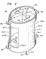
- a first presently preferred embodiment 10 of our novel elliptical cross-section slotted-tube radio-frequency resonator for nuclear magnetic resonance imaging is illustrated.
- the resonator has a central axis 10a; the resonator is normally positioned with the NMR static field parallel to axis 10a.
- Resonator 10 comprises first and second outer structure portions 11-1 and 11-2 formed about an inner structure comprised of a lower guard ring 12a and an upper guard ring 12b.
- the guard rings are-continuous conductors of substantially identical shape, but spaced from one another in the direction of the central axis 10a of the resonator.
- a guard ring feed terminal 12-0 is connected to that edge of lower guard ring 12a furthest from upper guard ring 12b, at a position thereon underlying a resonator outer structure feed point 11-0.
- a dielectric member 14 is interposed between at least each of lower and upper guard rings 12a and 12b and the overlying portions of outer structure portions 11-1 and 11-2.
- the dielectric member 14 is a one-piece member having an elliptical cross-section in planes substantially orthogonal to the direction of resonator central axis 10-a, and extends from at least the lower edge of lower guard ring 12a to the upper-edge of upper guard ring 12b; the presence of the insulative material of member 14 in a pair of window areas lOw-1 and lOw-2, devoid of any portion of outer structure 11 or inner structure 12, does not substantially affect the radio-frequency operation of the resonator, yet provides additional structural integrity thereto.
- Member 14 can be fabricated of any suitable material having a low loss factor at the frequency of use; plastic, glass or ceramic material can be used.
- Each of outer structure portions 11-1 and 11-2 (best viewed in Figure la) comprises an I-shaped electrode each having a relatively wide central band lla-1 or lla-2 which has wing portions extending to the right and left thereof at both the upper and lower central band side edges lla-la and lla-lb or lla-2a and lla-2b.
- central band lla-1 extended from the respective lower right and left peripheral edges lla-la and lla-lb, respectively, of central band lla-1 are respective lower right wing portion llw-la and lower left wing portion llw-la' and extended from the upper portions of central band side edges lla-la and lla-lb, respectively are respective upper right wing portion llw-lb and upper left wing portion llw-lb'.
- lower left wing portion llw-2a and lower right wing portion llw-2a' respectively extend from the lower peripheries of second central band sides lla-2a and lla-2b, respectively, while respective upper left wing portion llw-2b and upper right wing portion llw-2b' respectively extend from the respective upper sides of second central band lla-2.
- the outer structure feed portion 11-0 extends from the lower edge of first central band lla-1, substantially along a line midway between the side edges thereof (e.g. substantially at one of the points of maximum cross-section curvature).
- Each of outer structure portions 11-1 and 11-2 are advantageously fabricated from a flat sheet, typically having a thickness on the order of about 5 milli-inches (i.e..005"), of a highly conductive material, such as copper and the like.
- Each outer structure section 11-1 and 11-2 may have a substantially rectangular central band section lla-1 and lla-2, and substantially rectangular wing sections llw-la, llw-la', llw-lb and llw-lb' or llw-2a, llw-2a', llw-2b and llw-2b'.
- central band sides lla-la and lla-lb or lla-2a and lla-2b lie along straight lines either parallel to the resonator central axis 10a (as illustrated) or skewed at some angle thereto, or to deviate from a substantially straight edge, so as to be concave, convex or of more complex convoluted form with respect to a line joining the end points of the central band sides.
- each of wing portions llw-la, llw-la', llw-2a, llw-2a', llw-lb, llw-lb', llw-2b and llw-2b' are advantageously formed as rectangular extensions from the associated central band sides, but may have the upper and lower edges thereof formed, when the pair of outer structure electrodes 11-1 and 11-2 are bent to the desired elliptical cross-sectioned shape, to be either in one of a number of parallel planes substantially orthogonal to the resonator central axis 10a or to be skewed therefrom; advantageously, each of outer structure portions 11-1 and 11-2 will be symmetrical about resonator axis 10a and complementary to the other outer structure portion.
- the wing edges 16-la, 16-la', 16-lb, 16-lb', 16-2a, 16-2a', 16-2b and 16-2b' are straight edges lying parallel to resonator axis 10a such that adjacent pair of edges (e.g. wing edge pairs 16-la and 16-2a, 16-la' and 16-2a', 16-lb and 16-2b, and 16-lb' and 16-2b') are parallel to one another but spaced apart over the wing edge lengths W thereof, to form associated outer structure wing gaps llg-1, 11g'-1, llg-2 and llg'-2, respectively.
- adjacent pair of edges e.g. wing edge pairs 16-la and 16-2a, 16-la' and 16-2a', 16-lb and 16-2b, and 16-lb' and 16-2b'
- the distance of each of gaps llg-1, llg-2, llg'-l and llg'-2 are on the order of one-eighth inch.
- Outer resonator structure portions 11-1 and 11-2 are, as previously mentioned hereinabove, formed into a tube having an elliptical cross-section, in planes substantially perpendicular to resonator central axis 10a. This geometry has a better fit to the cross-section of the body or head to be imaged and allows for a better coil-filling-factor, than does a round cross-section.
- the central band portions lla-1 and lla-2 of the two outer structure portions 11-1 and 11-2 respectively, subtend angles 0 to each side of the major axis M; advantageously, angle 0 is in the range of 30-50° and is most preferably about 40°.
- each of windows lOw-1 and lOw-2 subtend an angle of (180-20)°, e.g. about 100°, if 0 is 40°.
- the principal useful RF magnetic field generated by the resonator is substantially directed parallel to an axis drawn through the centers of windows lOw-1 and lOw-2, i.e. in a direction perpendicular to the resonator axis 10a.
- Each of inner structure lower and upper guard rings 12a and 12b are also formed of a highly conductive material, e.g. copper and the like, typically as_a band of a conductive foil, having a thickness on the order of 5 milli-inches, and attached to the interior surface of the elliptical cross-section dielectric member 14.
- a single strip of foil may be utilized to fabricate each of bands 12a or 12b, with the foil ends being joined together in essentially conductive manner to complete each of the elliptical guard rings.
- Each ring has a dimension W' which is substantially, though not necessarily exactly, equal to the dimension W of the overlying outer structure wing portions.
- each elliptically cross-sectioned guard ring has a major axis M' of dimension slightly less than the dimension M of the major axis of the outer structure, by an amount substantially equal to twice the thickness G of dielectric member 14, and has a minor axis M' of dimension slightly less than the minor axis M of the outer structure, by an amount substantially equal to twice the thickness G of the interposed dielectric member 14.
- the dielectric member thickness G is chosen, typically in the range of about 1/32" to about 5/8", to tune the natural unloaded resonance of the resonator to a frequency about 10% higher than the desired NMR imaging frequency to be used.
- a first coupling capacitor 18a is connected between the ends of adjacent wings llw-la and llw-2a and a second coupling capacitor 18b is connected between the ends of wings llw-lb and llw-2b.
- a third coupling capacitor 18b' is connected (Figure 1c) between the ends of adjacent wings llw-lb' and llw-2b', across the gap llg'-2 therebetween, while a -fourth capacitive coupling element 18a' (not visible in the views of Figures 1 and 1a-1c) is connected between the ends of lower wings llw-la' and llw-2a', across the gap llg'-l therebetween.
- Each of the four wing-gap capacitances (selected to tune, in conjunction with the member 14 thickness G dimension, the resonator to resonance at or slightly above the desired NMR imaging frequency of operation) may be a fixed or variable type and should possess as high a quality Q factor as possible at the frequency of intended use.
- Each coupling capacitance 18 may be of any form desired, such as the fixed-value, tubular capacitances 18a and 18b shown in Figure 1, the fixed-value chip capacitor structures 18b and 18b' shown in Figure lc or of suitable variable configuration, such as air, quartz, sapphire and the like dielectric variable trimmer capacitors, of piston or other types well known to the variable capacitor arts.
- suitable variable configuration such as air, quartz, sapphire and the like dielectric variable trimmer capacitors, of piston or other types well known to the variable capacitor arts.
- variable capacitance can take either of the forms shown in Figure 1d; the total inter-wing coupling capacitance can be formed either by the parallel combination of a variable capacitance 18-bl and a fixed capacitance 18-b2, where the total capacitance required is greater than the maximum capacitance of variable capacitor 18-bl alone, or by the series connection of variable capacitor 18-bl' and fixed capacitor 18-b2', where the minimum capacitance required may be less than the minimum capacitance available from variable capacitor 18-bl' alone.
- a particularly rugged wing-gap tuning capacitance 18' can be fabricated as shown in Figure le, by use of double-sided printed circuit board material.
- the printed circuit board capacitor 18' is moved adjacent to wing ends 16-lb and 16-2b, between which the gap llg-2 has been previously adjusted to equal the thickness T of the printed circuit capacitor dielectric thickness.
- the wing ends 16-lb and 16-2b are respectively joined to the abutting ends of circuit board conductor portions 18w-1 and 18w-2, as by soldering, welding and the like processes.
- Capacitor 18' is, advantageously, fabricated of a printed circuit board having a very low loss- tangent substrate 18c material, such as glass-Teflon R and the like, and with the substrate 18c of a standard thickness, such as 1/32 inch, 1/16 inch and the like.
- Each printed circuit capacitor 18' can be tuned by trimming the length X thereof, by cutting, filing and the like processes, whereby the total equivalent capacitance C of each of the four capacitors 18 can be adjusted for the desired symmetry of the radio-frequency field within the resonator.
- the same adjustment of the four wing-gap bridging capacitances C can be effected by use of either method shown in Figure ld or by selection of the exact values of fixed value capacitance, if variable capacitance cannot, for some reason, be utilized.
- an elliptical cross-section slotted-tube radio-frequency resonator 10 for body imaging has a major axis M' dimension of about 17 inches and a minor axis m dimension of about 13 inches, for an eccentricity ratio e of about 1.3, with a height H of about 21 inches, a wing end height W of about 4 inches and a window height S of 13 inches.
- Dielectric tube 14 may have a thickness G of between 1/32 inch and about 5/8 inch, whereby the inner guard ring major axis M' dimension is between about 15 3/4inches and about 17 inches and the minor axis m is between about 11 3/4 inches and about 13 inches, dependent upon the actual dielectric tube thickness G utilized and the thickness of the outer structure and inner guard ring electrodes.
- the inner guard ring height W' is also about 4 inches and the spacing S' therebetween is about 13 inches. This resonator is relatively easily tuned to the approximately 64 MHz. resonance frequency for 1 H imaging at a field of 1.5 Tesla.
- an elliptical cross-section, slotted-tube radio-frequency resonator 10 was built utilizing a tube 14 of about 5/16 inch thickness G, with an outer structure major axis M dimension of about 11 3/8 inches and minor axis m dimension of about 8 3/4 inches; the resonator height H is about 11 1/4 inches with wing height W and inner guard ring height W' of about 1 3/4 inches, a window height S and inner guard ring separation S' of about 7 3/4 inches and a window periphery, between complementary band portion edges lla-la and lla-2a or lla-lb and lla-2b of about 8 1/4 inches.
- variable capacitors 18 are tuned using variable capacitors 18 across all four inter-wing gaps llg-1, llg'l, llg-2 and llg'-2.
- NMR frequencies in the complete range of about 20 MHz. to 75 MHz. are accessible using the variable wing-gap capacitors 18 alone, without requiring readjustment of the inner ring to outer electrode gap distance G.
- resonator 10 provides an unloaded quality factor Q U of about 225 in the 60 MHz. range and a loaded quality factor Q L of about 25 when loaded by the insertion of a patient's head within the interior resonator volume.
- the ratio of loaded to unloaded Q is thus about one-ninth, assuring that the resonator provides significantly less noise/loss contribution than the body portion being imaged.
- the first and second outer vertical bands 11a-1' and lla-2' of the respective first and second outer structure portions 11-1' and 11-2' are, as shown in Figure 2, placed about the portion of least curvature of the elliptical cross-section, rather than about the greatest curvature ends of the resonator, as in the embodiment 10.
- the angle e' is formed between each of the central band edges lla-la', lla-lb', Ila-2a' and lla-2b', and the minor axis m, and is again preferably on the order of 40°.
- Embodiment 20 offers windows 20w-1 and 20w-2 of somewhat reduced area and may provide a somewhat reduced loaded quality factor Q L , resulting in reduced resonator loss/noise contributions due to the greater optimization of filling factor obtained when a portion of a patient's body, such as the head, arm, leg and the like, fills the elliptical cross section of resonator 20, as opposed to the decrease in loaded quality factor Q L of resonator 10.
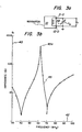
- Figure 3b illustrates the terminal impedance Z r of the resonator connected in the circuit of Figure 3a, plotted along ordinate 40, for frequencies, plotted along abscessa 42, in the range from about 30 MHz. to about 100 MHz., for a 1 H resonator at an unloaded resonant frequency of about 63 MHz. and tuned to resonance with an additional variable parallel capacitance C p of about 30 picofarad maximum value, shown in Figure 3a.
- the extrema of curve 45 at about 41 MHz., 63 MHz.
- each of these extrema corresponds to a frequency at which the reactive component of the resonator impedance Z r is zero. It will be seen that two of these extrema correspond to minima of the measured impedance Z , and a third extrema 45a corresponds to a maxima.
- the resonances corresponding to Z r minima it is more desirable to use the high-impedance parallel-resonance point 45a, at which the impedance Z r is on the order of 400 ohms in this example, because the resistance of connecting cables is likely to be comparable to the values of Z r at the minima.
- the connecting cables could therefore contribute a more significant proportion of noise to the detected NMR signal.
- the elliptically cross-sectioned slotted-tube radio-frequency resonator of the present invention provides a minimal --noise/loss contribution to the NMR imaging signal. This is particularly important in that a single radio-frequency resonator is normally utilized, with an external " transmit/receive switch.(not shown) for both excitation of the imaged sample and subsequent reception of the image return signal. Thus, the proportion of the excitation signal dissipated by the resonator is reduced, while the signal-to-noise ratio of the image return signal is maximized.
- a very course adjustment factor is provided by varying the distance G between the inner guard rings 12 and outer electrodes 11-1 and 11-2.
- the particular resonator resonance frequency to be used e.g. point 45a
- the desired NMR frequency e.g. is at about 70-90 MHz. if it is desired to operate at about 63 MHz.
- the capacitance between inner guard ring members 12 and outer electrode portions 11-1 and 11-2 is inversely proportional to distance G, the larger the value of distance G, the higher the natural resonator frequency obtained.
- the four inter-wing gap capacitors 18 are added between the wing portions of the outer electrodes. These gap capacitors are adjusted to lower the particular resonator resonance frequency substantially to, but not below, the NMR frequency.
- a final adjustment factor is provided by the parallel capacitance C p of input capacitor 38 (see Figure 3a).
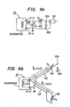
- the circuit of Figure 4a schematically illustrates the final circuit utilized to match resonator 10 (or resonator 20 of Figure 2) to the system impedance Z , between antenna terminals 10a and lOb.
- a series tuning capacitance 48 is connected between antenna feed terminal 10a and resonator feed terminal 11-0 and the associated terminal of capacitor 38.
- instrumentation would be provided between antenna coaxial cable 50 and the antenna terminals 10a and lOb, to measure forward and reflected power and allow capacitors 38 and 48 to be adjusted for minimum reflected power at the desired frequency of operation, with a resonator loaded by the sample to be imaged.
- impedance adjustment and matching circuitry may be equally as well utilized and may contain-inductive, in lieu of, or in addition to, capacitive elements.
- each of cables 52 and/or 54 is a coaxial cable having a physical length 1 1 or 1 2 equal to one-half of an effective cable wavelength ( ⁇ e /2) at the frequency of operation or equal to an integral multiple of one-half of an effective cable wavelength. It is well known to the art to calculate the effective wavelength of a particular cable, e.g. for a 50 ohm coaxial cable having an effective velocity of propagation of about 0.666, a one-half wavelength line at about 60 MHz. (i.e. a wavelength of about 5 meters) has a length 1 of about 65 1/2" and allows the adjusting personnel to be positioned at a distance of almost 5 1/2' from the loaded resonator.
- each of cables 52 and 54 can be increased in multiples of one-half wavelength and still have the value of capacitors 38 and 48 be the same as that required if the capacitor were connected directly to resonator terminal 11-0, capacitors 38 and 48 can easily be located outside of the imaging magnet bore and the loaded resonator can be adjusted in the exact location of use, compensating for substantially all loading elements.
Abstract
Description
- The present application relates to nuclear magnetic resonance (NMR) imaging and, more particularly, to a novel slotted-tube radio-frequency (RF) resonator having an ellip-tical cross-section, for use in obtaining NMR images in a NMR imaging system.
- There has hitherto been wide speculation in NMR publications (such as "Radio Frequency Coil Technology NMR Scanning", D. Hoult, Proc. Internat. Symp. on NMR Imaging (1982), pages 33-39; "NMR Imaging and Biomedicine", P. Mansfield et al., Academic Press (1982), pages 174-187; "Positron Tomography and Nuclear Magnetic Resonance Imaging", G. Brownel et al., Science, (1982) issue 215, pages 619-626; "NMR Imaging in Medicine", I. Pykett, Scientific American (1982) issue 246, pages 78-88; and other publications) that hydrogen head and/or body imaging would be unfeasible in a static NMR imaging field of magnitude much above about 0.5 Tesla (T), at least in part due to the problem of providing suitable NMR imaging coils at the Larmor frequencies, typically in the range from about 20 MHz. to about 100 MHz., associated with the greater static field magnitudes. It is well known that conventional "half turn" saddle coil, Helmholtz and solenoidal geometries are generally unsuited and precluded for head and body-sized NMR imaging coils at frequencies above about 30 MHz. due to their self-resonant properties, and thus would be unusable at the approximately 64 MHz. imaging frequency for 1 H resonance in an imaging system utilizing a static field of about 1.5 T magnitude.
- A slotted-tube resonator has been used at an even higher frequency of 300 MHz., for small-sample 1H NMR analysis, but this resonator (described by D. Alderman et al., in "An Efficient Decoupler Coil Design which Reduces Heating in Conductive Samples in Safer Conducting Spectrometers", Volume 36, J. of Mag. Resonance, pp. 447-451, 1979), has such a small working volume diameter (e.g. about .72") as to preclude access of the human head, extremities and/or torso therein for imaging purposes.
- It is also well known that the frequency dependence of the signal-to-noise ratio (S/N) in an NMR imaging system in which system noise contributions and dielectric losses in the sample have been minimized, is given by the formula:

- Accordingly, it is desirable to provide a radio-frequency coil for NMR imaging which will not only be capable of operation at the Larmor frequencies (between about 20 MHz. to about 100 MHz.) associated with static magnetic fields of magnitude greater than about 0.5 Tesla, but will also have a relatively insignificant loss contribution compared to the losses introduced by the object being imaged. The ratio of the RF coil quality Q factor measured with the NMR coil substantially filled or loaded by the body (QL) can be compared to the Q factor measured with the coil empty or unloaded (Qu) and is a measure of the relative noise contribution from the RF coil. Therefore, a high QU/QL ratio is most desirable to optimize the signal-to-noise ratio for NMR imaging.
- In accordance with the invention, a radio-frequency coil, for nuclear magnetic resonance imaging at Larmor frequencies associated with.a static magnetic field of magnitude greater than about 0.5 Tesla, comprises a slotted-tube radio-frequency resonator having an elliptical cross-section. The resonator contains first and second complementary outer structure portions having relatively wide bands connecting juxtaposed wing structures, with the end of each of the four wings (leftwardly and rightwardly arranged respectively at the top and bottom of each outer structure portion band) being spaced from a complementary one of the wing portions of the other outer structure portion band and capacitively coupled thereto. An inner guard structure utilizes a pair of elliptical rings placed substantially in registration with the elliptical portions of the outer structure formed by the capacitively-coupled juxtaposed upper or lower wing portions. The resonator wings and band portions define a pair of complementary windows, which may be placed upon either the regions of greatest or least curvature of the elliptical cross-sectioned resonator. One of the guard rings is directly connected to system common potential while radio-frequency energy is coupled to one of the complementary outer section portions at an edge substantially at the midpoint of a band portion thereof. The eccentricity ratio of the elliptical cross-section of the resonator and the resonator dimensions are arranged to provide an interior volume into which a human head or body extremity can be placed and which human body portion fills the interior volume of the resonator to an extent such that the quality factor QL of the resonator is reduced by about one order of magnitude with respect to the unloaded resonator quality factor.
- In presently preferred embodiments, for 1 H and 19 F imaging at about 64 megacycles and about 60 MHz., respectively, in a 1.5 Tesla static imaging field, elliptical eccentricity ratios of about 1.3:1 are utilized.
- Accordingly, it is one object of-the present invention to provide a novel slotted-tube radio-frequency resonator having an elliptical cross-section for use in a nuclear magnetic resonance imaging system.
- This and other objects of the present invention will become apparent upon reading of the following detailed description, when read in conjunction with the drawings.
-
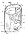
- Figure 1 is a perspective view of a first presently preferred embodiment of an elliptical cross-section, slotted-tube radio-frequency resonator for NMR imaging, in accordance with the principles of the present invention;
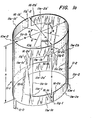
- Figure la is a perspective view of the outer portions of the resonator of Figure 1, and useful in appreciating the various terms of resonator technology utilized herein;
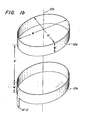
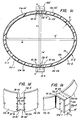
- Figure 1b is a perspective view of the inner guard ring structure of the resonator of Figure 1;
- Figure lc is a top view of the resonator of Figure 1, and particularly illustrating the capacitive coupling utilized between registered complementary wing end portions of the resonator outer structure;
- Figures ld and le are portions of the complementary wing end structures, illustrating various means of capacitive coupling therebetween;
- Figure 2 is a perspective view of another presently preferred resonator embodiment, in which the outer structure band portions are arranged about the portions of minimal curvature and the resonator windows are arranged at portions of maximum resonator curvature;
- Figure 3a is a circuit representation illustrating the tuning of the resonator of the present invention;
- Figure 3b is a graph of the impedance versus frequency of the tuned resonator of Figure 3a;
- Figure 4a is a circuit diagram illustrating the circuit for simultaneously tuning and matching of a resonator to a standard coaxial cable; and
- Figure 4b is a schematic diagram illustrating a presently preferred configuration for achieving the circuit of Figure 4a, with tuning and matching capacitances both remotely located from the resonator and having minimal effect thereon during capacitor adjustments.
- Referring initially to Figures 1 and la-lc, a first presently preferred
embodiment 10 of our novel elliptical cross-section slotted-tube radio-frequency resonator for nuclear magnetic resonance imaging is illustrated. The resonator has acentral axis 10a; the resonator is normally positioned with the NMR static field parallel toaxis 10a.Resonator 10 comprises first and second outer structure portions 11-1 and 11-2 formed about an inner structure comprised of alower guard ring 12a and anupper guard ring 12b. The guard rings are-continuous conductors of substantially identical shape, but spaced from one another in the direction of thecentral axis 10a of the resonator. A guard ring feed terminal 12-0 is connected to that edge oflower guard ring 12a furthest fromupper guard ring 12b, at a position thereon underlying a resonator outer structure feed point 11-0. Adielectric member 14 is interposed between at least each of lower andupper guard rings dielectric member 14 is a one-piece member having an elliptical cross-section in planes substantially orthogonal to the direction of resonator central axis 10-a, and extends from at least the lower edge oflower guard ring 12a to the upper-edge ofupper guard ring 12b; the presence of the insulative material ofmember 14 in a pair of window areas lOw-1 and lOw-2, devoid of any portion of outer structure 11 or inner structure 12, does not substantially affect the radio-frequency operation of the resonator, yet provides additional structural integrity thereto.Member 14 can be fabricated of any suitable material having a low loss factor at the frequency of use; plastic, glass or ceramic material can be used. - Each of outer structure portions 11-1 and 11-2 (best viewed in Figure la) comprises an I-shaped electrode each having a relatively wide central band lla-1 or lla-2 which has wing portions extending to the right and left thereof at both the upper and lower central band side edges lla-la and lla-lb or lla-2a and lla-2b. Thus, extended from the respective lower right and left peripheral edges lla-la and lla-lb, respectively, of central band lla-1 are respective lower right wing portion llw-la and lower left wing portion llw-la' and extended from the upper portions of central band side edges lla-la and lla-lb, respectively are respective upper right wing portion llw-lb and upper left wing portion llw-lb'. Similarly, lower left wing portion llw-2a and lower right wing portion llw-2a' respectively extend from the lower peripheries of second central band sides lla-2a and lla-2b, respectively, while respective upper left wing portion llw-2b and upper right wing portion llw-2b' respectively extend from the respective upper sides of second central band lla-2. The outer structure feed portion 11-0 extends from the lower edge of first central band lla-1, substantially along a line midway between the side edges thereof (e.g. substantially at one of the points of maximum cross-section curvature). Each of outer structure portions 11-1 and 11-2 are advantageously fabricated from a flat sheet, typically having a thickness on the order of about 5 milli-inches (i.e..005"), of a highly conductive material, such as copper and the like. Each outer structure section 11-1 and 11-2 may have a substantially rectangular central band section lla-1 and lla-2, and substantially rectangular wing sections llw-la, llw-la', llw-lb and llw-lb' or llw-2a, llw-2a', llw-2b and llw-2b'. It is entirely within the scope of the present invention to have the central band sides lla-la and lla-lb or lla-2a and lla-2b lie along straight lines either parallel to the resonator
central axis 10a (as illustrated) or skewed at some angle thereto, or to deviate from a substantially straight edge, so as to be concave, convex or of more complex convoluted form with respect to a line joining the end points of the central band sides. Similarly, each of wing portions llw-la, llw-la', llw-2a, llw-2a', llw-lb, llw-lb', llw-2b and llw-2b' are advantageously formed as rectangular extensions from the associated central band sides, but may have the upper and lower edges thereof formed, when the pair of outer structure electrodes 11-1 and 11-2 are bent to the desired elliptical cross-sectioned shape, to be either in one of a number of parallel planes substantially orthogonal to the resonatorcentral axis 10a or to be skewed therefrom; advantageously, each of outer structure portions 11-1 and 11-2 will be symmetrical aboutresonator axis 10a and complementary to the other outer structure portion. It is highly advantageous that the wing edges 16-la, 16-la', 16-lb, 16-lb', 16-2a, 16-2a', 16-2b and 16-2b' are straight edges lying parallel toresonator axis 10a such that adjacent pair of edges (e.g. wing edge pairs 16-la and 16-2a, 16-la' and 16-2a', 16-lb and 16-2b, and 16-lb' and 16-2b') are parallel to one another but spaced apart over the wing edge lengths W thereof, to form associated outer structure wing gaps llg-1, 11g'-1, llg-2 and llg'-2, respectively. Dependent upon the height H from the bottom to top edges of the outer structure portions 11-1 and 11-2, a pair of complementary windows are formed of height S, where S=H-2W. For the resonators of presently preferred embodiments, the distance of each of gaps llg-1, llg-2, llg'-l and llg'-2 are on the order of one-eighth inch. - Outer resonator structure portions 11-1 and 11-2 are, as previously mentioned hereinabove, formed into a tube having an elliptical cross-section, in planes substantially perpendicular to resonator
central axis 10a. This geometry has a better fit to the cross-section of the body or head to be imaged and allows for a better coil-filling-factor, than does a round cross-section. The tube has a major axis M and a minor axis m, defining an eccentricity ratio e, where e=M/m; eccentricity ratio e is always greater than 1 (where e=l defines a resonator of circular cross-section) and is preferredly in the range of 1.1-2.0, and more preferably in the range of 1.2-1,4. For any chosen eccentricity ratio, the central band portions lla-1 and lla-2 of the two outer structure portions 11-1 and 11-2, respectively, subtend angles 0 to each side of the major axis M; advantageously, angle 0 is in the range of 30-50° and is most preferably about 40°. Thus, each of windows lOw-1 and lOw-2 subtend an angle of (180-20)°, e.g. about 100°, if 0 is 40°. The principal useful RF magnetic field generated by the resonator is substantially directed parallel to an axis drawn through the centers of windows lOw-1 and lOw-2, i.e. in a direction perpendicular to theresonator axis 10a. - Each of inner structure lower and
upper guard rings dielectric member 14. A single strip of foil may be utilized to fabricate each ofbands lower guard ring 12a is separated from the lower edge ofupper guard ring 12b by a spacing distance S', which is substantially equal to the window dimension S of the outer structure. Each elliptically cross-sectioned guard ring has a major axis M' of dimension slightly less than the dimension M of the major axis of the outer structure, by an amount substantially equal to twice the thickness G ofdielectric member 14, and has a minor axis M' of dimension slightly less than the minor axis M of the outer structure, by an amount substantially equal to twice the thickness G of the interposeddielectric member 14. The dielectric member thickness G is chosen, typically in the range of about 1/32" to about 5/8", to tune the natural unloaded resonance of the resonator to a frequency about 10% higher than the desired NMR imaging frequency to be used. - One of a plurality of capacitive coupling means 18, such as a fixed-capacitance chip capacitor and the like, is connected between the ends of adjacent wings. Thus, a
first coupling capacitor 18a is connected between the ends of adjacent wings llw-la and llw-2a and asecond coupling capacitor 18b is connected between the ends of wings llw-lb and llw-2b. Athird coupling capacitor 18b' is connected (Figure 1c) between the ends of adjacent wings llw-lb' and llw-2b', across the gap llg'-2 therebetween, while a -fourthcapacitive coupling element 18a' (not visible in the views of Figures 1 and 1a-1c) is connected between the ends of lower wings llw-la' and llw-2a', across the gap llg'-l therebetween. Each of the four wing-gap capacitances, (selected to tune, in conjunction with themember 14 thickness G dimension, the resonator to resonance at or slightly above the desired NMR imaging frequency of operation) may be a fixed or variable type and should possess as high a quality Q factor as possible at the frequency of intended use. Eachcoupling capacitance 18 may be of any form desired, such as the fixed-value,tubular capacitances chip capacitor structures resonator 10 both to a desired degree of symmetrical or assymetrical RF field homogenity and to a resonant condition at a particular operating frequency determined by the particular imaging system with which the resonator is to be used, it is highly desirable to provide a variable capacitance at at least one of the four inter-wing gaps. The variable capacitance can take either of the forms shown in Figure 1d; the total inter-wing coupling capacitance can be formed either by the parallel combination of a variable capacitance 18-bl and a fixed capacitance 18-b2, where the total capacitance required is greater than the maximum capacitance of variable capacitor 18-bl alone, or by the series connection of variable capacitor 18-bl' and fixed capacitor 18-b2', where the minimum capacitance required may be less than the minimum capacitance available from variable capacitor 18-bl' alone. - Most advantageously, we have found that a particularly rugged wing-gap tuning capacitance 18' can be fabricated as shown in Figure le, by use of double-sided printed circuit board material. The printed circuit board material is cut into a strip of width W " , approximately equal to the dimension W of the wing ends (to avoid discontinuities at the interface between the wings and end-capacitor 18'), and with a length X somewhat greater than the length calculated to provide a capacitance, based on the capacitive plate area A (A = X x W") and the dielectric constant of the printed circuit dielectric insulative substrate 18c sandwiched between the first and
second conductors 18w-1 and 18w-2. The printed circuit board capacitor 18' is moved adjacent to wing ends 16-lb and 16-2b, between which the gap llg-2 has been previously adjusted to equal the thickness T of the printed circuit capacitor dielectric thickness. The wing ends 16-lb and 16-2b are respectively joined to the abutting ends of circuitboard conductor portions 18w-1 and 18w-2, as by soldering, welding and the like processes. Capacitor 18' is, advantageously, fabricated of a printed circuit board having a very low loss- tangent substrate 18c material, such as glass-Teflon R and the like, and with the substrate 18c of a standard thickness, such as 1/32 inch, 1/16 inch and the like. Each printed circuit capacitor 18' can be tuned by trimming the length X thereof, by cutting, filing and the like processes, whereby the total equivalent capacitance C of each of the fourcapacitors 18 can be adjusted for the desired symmetry of the radio-frequency field within the resonator. The same adjustment of the four wing-gap bridging capacitances C can be effected by use of either method shown in Figure ld or by selection of the exact values of fixed value capacitance, if variable capacitance cannot, for some reason, be utilized. - By way of example only, in a nuclear magnetic resonance whole-body imaging system utilizing a 1.5 T superconducting magnet, an elliptical cross-section slotted-tube radio-
frequency resonator 10 for body imaging has a major axis M' dimension of about 17 inches and a minor axis m dimension of about 13 inches, for an eccentricity ratio e of about 1.3, with a height H of about 21 inches, a wing end height W of about 4 inches and a window height S of 13 inches.Dielectric tube 14 may have a thickness G of between 1/32 inch and about 5/8 inch, whereby the inner guard ring major axis M' dimension is between about 15 3/4inches and about 17 inches and the minor axis m is between about 11 3/4 inches and about 13 inches, dependent upon the actual dielectric tube thickness G utilized and the thickness of the outer structure and inner guard ring electrodes. The inner guard ring height W' is also about 4 inches and the spacing S' therebetween is about 13 inches. This resonator is relatively easily tuned to the approximately 64 MHz. resonance frequency for 1 H imaging at a field of 1.5 Tesla. For 1H or 19 F head imaging in the same system, at.an imaging frequency of about 64 or 60 MHz., respectively, an elliptical cross-section, slotted-tube radio-frequency resonator 10 was built utilizing atube 14 of about 5/16 inch thickness G, with an outer structure major axis M dimension of about 11 3/8 inches and minor axis m dimension of about 8 3/4 inches; the resonator height H is about 11 1/4 inches with wing height W and inner guard ring height W' of about 1 3/4 inches, a window height S and inner guard ring separation S' of about 7 3/4 inches and a window periphery, between complementary band portion edges lla-la and lla-2a or lla-lb and lla-2b of about 8 1/4 inches. The precise NMR frequency desired is tuned usingvariable capacitors 18 across all four inter-wing gaps llg-1, llg'l, llg-2 and llg'-2. In fact, NMR frequencies in the complete range of about 20 MHz. to 75 MHz. are accessible using the variable wing-gap capacitors 18 alone, without requiring readjustment of the inner ring to outer electrode gap distance G. - Typically,
resonator 10 provides an unloaded quality factor QU of about 225 in the 60 MHz. range and a loaded quality factor QL of about 25 when loaded by the insertion of a patient's head within the interior resonator volume. The ratio of loaded to unloaded Q is thus about one-ninth, assuring that the resonator provides significantly less noise/loss contribution than the body portion being imaged. - In another presently preferred
embodiment 20 of our novel elliptically cross-sectioned, slotted-tube radio-frequency resonator, the first and second outervertical bands 11a-1' and lla-2' of the respective first and second outer structure portions 11-1' and 11-2' are, as shown in Figure 2, placed about the portion of least curvature of the elliptical cross-section, rather than about the greatest curvature ends of the resonator, as in theembodiment 10. Inresonator 20, the angle e' is formed between each of the central band edges lla-la', lla-lb', Ila-2a' and lla-2b', and the minor axis m, and is again preferably on the order of 40°.Embodiment 20 offerswindows 20w-1 and 20w-2 of somewhat reduced area and may provide a somewhat reduced loaded quality factor QL, resulting in reduced resonator loss/noise contributions due to the greater optimization of filling factor obtained when a portion of a patient's body, such as the head, arm, leg and the like, fills the elliptical cross section ofresonator 20, as opposed to the decrease in loaded quality factor QL ofresonator 10. - Figure 3b illustrates the terminal impedance Zr of the resonator connected in the circuit of Figure 3a, plotted along
ordinate 40, for frequencies, plotted alongabscessa 42, in the range from about 30 MHz. to about 100 MHz., for a 1H resonator at an unloaded resonant frequency of about 63 MHz. and tuned to resonance with an additional variable parallel capacitance Cp of about 30 picofarad maximum value, shown in Figure 3a. The extrema ofcurve 45, at about 41 MHz., 63 MHz. and 71 MHz., are natural resonant frequencies of the resonator structure, that is, each of these extrema corresponds to a frequency at which the reactive component of the resonator impedance Zr is zero. It will be seen that two of these extrema correspond to minima of the measured impedance Z , and athird extrema 45a corresponds to a maxima. Although it is possible to use the resonances corresponding to Zr minima for NMR applications, it is more desirable to use the high-impedance parallel-resonance point 45a, at which the impedance Zr is on the order of 400 ohms in this example, because the resistance of connecting cables is likely to be comparable to the values of Zr at the minima. In this instance, the connecting cables could therefore contribute a more significant proportion of noise to the detected NMR signal. We therefore preferentially use thehigh impedance resonance 45a, which parallel-resonance point is tuned to coincide with the NMR frequency. It has been found that, with a human head present inside this elliptically cross-sectioned slotted-tube resonator, the resonant resistance of about 400 ohms falls to a value on the order of 40 ohms, indicative of the resonator providing only about 12% of the total noise/loss contributions and the object-to-be-imaged, e.g. the human head, accounting for about 88% of the noise/loss contributions. Thus, the elliptically cross-sectioned slotted-tube radio-frequency resonator of the present invention provides a minimal --noise/loss contribution to the NMR imaging signal. This is particularly important in that a single radio-frequency resonator is normally utilized, with an external "transmit/receive switch.(not shown) for both excitation of the imaged sample and subsequent reception of the image return signal. Thus, the proportion of the excitation signal dissipated by the resonator is reduced, while the signal-to-noise ratio of the image return signal is maximized. - It will be seen that three factors are provided for tuning the resonator to the NMR frequency. Initially, a very course adjustment factor is provided by varying the distance G between the inner guard rings 12 and outer electrodes 11-1 and 11-2. We presently prefer to use a sufficiently large distance G that the particular resonator resonance frequency to be used (
e.g. point 45a) is substantially above the desired NMR frequency (e.g. is at about 70-90 MHz. if it is desired to operate at about 63 MHz.), in the absence of anyinter-wing gap capacitors 18. Since the capacitance between inner guard ring members 12 and outer electrode portions 11-1 and 11-2 is inversely proportional to distance G, the larger the value of distance G, the higher the natural resonator frequency obtained. As a second factor, the fourinter-wing gap capacitors 18 are added between the wing portions of the outer electrodes. These gap capacitors are adjusted to lower the particular resonator resonance frequency substantially to, but not below, the NMR frequency. A final adjustment factor is provided by the parallel capacitance Cp of input capacitor 38 (see Figure 3a). - Because of the change in load resistance, as well as the change in resonant frequency, represented by the sample- loaded resonator with respect to the unloaded resonator, the total impedance must be adjusted for a low-reflectivity match to the system impedance, which is typically on the order of 50 ohms. The circuit of Figure 4a schematically illustrates the final circuit utilized to match resonator 10 (or
resonator 20 of Figure 2) to the system impedance Z , betweenantenna terminals 10a and lOb. In addition to theparallel capacitance 38, of capacitor magnitude Cp (also shown in Figure 3a), aseries tuning capacitance 48, of capacitive magnitude C , is connected betweenantenna feed terminal 10a and resonator feed terminal 11-0 and the associated terminal ofcapacitor 38. As is well known in the art, instrumentation (not shown) would be provided between antennacoaxial cable 50 and theantenna terminals 10a and lOb, to measure forward and reflected power and allowcapacitors - Referring now to Figure 4b, because it is often inconvenient to adjust the final tuning capacitance and matching circuit reactance at the resonator input terminals 11-0 and 12-10 with the NMR sample in place and the entire structure located within the main static field of the imaging magnet, it is desirable that imaging test personnel be spatially removed from the location of
resonator 10 during the tuning procedure. In order to accomplish this spatial separation, yet have either theparallel capacitance 38 or theseries capacitance 48 appear to be connected to resonator feed terminal 11-0, at the frequency of operation, either or both of capacitors-38 and/or 48 can be connected between resonator terminals 11-0 and 12-0 by associatedcables 52 and/or 54, respectively. Advantageously, each ofcables 52 and/or 54, if used, is a coaxial cable having aphysical length length 1 of about 65 1/2" and allows the adjusting personnel to be positioned at a distance of almost 5 1/2' from the loaded resonator. Since thelength cables capacitors capacitors - While our novel elliptically cross-sectioned slotted-tube radio-frequency resonator for nuclear magnetic resonance imaging has been described with respect to several presently preferred embodiments thereof, many modifications and variations will now become apparent to those skilled in the art. It is our intent, therefore, to be limited only by the scope of the appending claims and not by the particular details and instrumentalities presented by way description of these presently preferred embodiments.
Claims (21)
Applications Claiming Priority (2)
| Application Number | Priority Date | Filing Date | Title |
|---|---|---|---|
| US06/609,043 US4641097A (en) | 1984-05-10 | 1984-05-10 | Elliptical cross-section slotted-tube radio-frequency resonator for nuclear magnetic resonance imaging |
| US609043 | 2009-10-30 |
Publications (2)
| Publication Number | Publication Date |
|---|---|
| EP0160942A2 true EP0160942A2 (en) | 1985-11-13 |
| EP0160942A3 EP0160942A3 (en) | 1987-04-15 |
Family
ID=24439133
Family Applications (1)
| Application Number | Title | Priority Date | Filing Date |
|---|---|---|---|
| EP85105377A Ceased EP0160942A3 (en) | 1984-05-10 | 1985-05-02 | Elliptical cross-section slotted-tube radio-frequency resonator for nuclear magnetic resonance imaging |
Country Status (6)
| Country | Link |
|---|---|
| US (1) | US4641097A (en) |
| EP (1) | EP0160942A3 (en) |
| JP (1) | JPS612404A (en) |
| KR (1) | KR850008093A (en) |
| FI (1) | FI851163L (en) |
| IL (1) | IL75025A0 (en) |
Cited By (11)
| Publication number | Priority date | Publication date | Assignee | Title |
|---|---|---|---|---|
| EP0171972A2 (en) * | 1984-08-16 | 1986-02-19 | Picker International, Inc. | Nuclear magnetic resonance radio frequency antenna |
| EP0222982A1 (en) * | 1985-11-18 | 1987-05-27 | Siemens Aktiengesellschaft | Surface coil for nuclear magnetic resonance analysis |
| US4720680A (en) * | 1986-02-18 | 1988-01-19 | Mitsubishi Denki Kabushiki Kaisha | Adjustable radio frequency coil for nuclear magnetic resonance imaging |
| EP0256370A1 (en) * | 1986-08-12 | 1988-02-24 | Siemens Aktiengesellschaft | Antenna arrangement for exciting and recording nuclear magnetic resonance |
| EP0257782A2 (en) * | 1986-08-07 | 1988-03-02 | Picker International, Inc. | Magnetic resonance apparatus |
| EP0268083A1 (en) * | 1986-10-28 | 1988-05-25 | Siemens Aktiengesellschaft | Surface resonator for nuclear spin tomography |
| US4755756A (en) * | 1986-02-18 | 1988-07-05 | Mitsubishi Denki Kabushiki Kaisha | Radio frequency coil for nuclear magnetic resonance imaging |
| US4837515A (en) * | 1986-09-26 | 1989-06-06 | Mitsubishi Denki Kabushiki Kaisha | Radio frequency coil for nuclear magnetic resonance imaging |
| WO1991000528A1 (en) * | 1989-07-05 | 1991-01-10 | MAX-PLANCK-Gesellschaft zur Förderung der Wissenschaften e.V. | Probe head for whole-body nuclear-resonance tomography or local in vivo nuclear-resonance spectroscopy |
| GB2258046A (en) * | 1991-07-10 | 1993-01-27 | Bruker Medizintech | Coil arrangement for measurements using magnetic resonance |
| US5542424A (en) * | 1993-03-25 | 1996-08-06 | Rochester Institute Of Technology | Resonator for magnetic resonance imaging |
Families Citing this family (32)
| Publication number | Priority date | Publication date | Assignee | Title |
|---|---|---|---|---|
| DE3579773D1 (en) * | 1984-07-31 | 1990-10-25 | Oxford Research Systems Ltd | METHOD AND DEVICE FOR DETERMINING MAGNETIC NUCLEAR RESONANCE SPECTRA AND COILS USED THEREOF. |
| JPS6144560U (en) * | 1984-08-27 | 1986-03-24 | 株式会社島津製作所 | High frequency signal transmitting/receiving terminal element for NMR imaging equipment |
| US4725780A (en) * | 1984-10-19 | 1988-02-16 | Mitsubishi Denki Kabushiki Kaisha | RF field generator and detector |
| JPS61176841A (en) * | 1985-02-01 | 1986-08-08 | Jeol Ltd | Coil for nmr probe |
| DE3515190A1 (en) * | 1985-04-26 | 1986-11-06 | Siemens AG, 1000 Berlin und 8000 München | CORE SPIN TOMOGRAPHY UNIT |
| US4950993A (en) * | 1985-11-29 | 1990-08-21 | Thomson-Cgr | Device and method for adjusting a radiofrequency antenna of a nuclear magnetic resonance apparatus |
| JPH0728857B2 (en) * | 1986-03-07 | 1995-04-05 | 株式会社日立製作所 | Inspection device using nuclear magnetic resonance |
| IL78767A (en) * | 1986-05-13 | 1989-09-10 | Elscint Ltd | Probe for nuclear magnetic resonance systems |
| JPH0423529Y2 (en) * | 1986-09-04 | 1992-06-02 | ||
| NL8603252A (en) * | 1986-12-22 | 1988-07-18 | Philips Nv | MAGNETIC RESONANCE DEVICE WITH CONVENIENT RF COIL. |
| US4875013A (en) * | 1987-03-13 | 1989-10-17 | Hitachi, Ltd. | High-frequency coil for nuclear magnetic imaging |
| JP2602223B2 (en) * | 1987-03-13 | 1997-04-23 | 株式会社日立製作所 | High frequency coil for nuclear magnetic resonance imaging |
| US4751464A (en) * | 1987-05-04 | 1988-06-14 | Advanced Nmr Systems, Inc. | Cavity resonator with improved magnetic field uniformity for high frequency operation and reduced dielectric heating in NMR imaging devices |
| JPS63292949A (en) * | 1987-05-25 | 1988-11-30 | Yokogawa Medical Syst Ltd | Rf coil for nuclear magnetic resonance imaging apparatus |
| US4783629A (en) * | 1987-10-07 | 1988-11-08 | The Regents Of The University Of California | RF coil for MRI with self-tracking ganged coupling capacitors |
| US5024229A (en) * | 1987-11-16 | 1991-06-18 | The University Of Rochester | Resonators for magnetic resonance imaging |
| US5139024A (en) * | 1987-11-16 | 1992-08-18 | The University Of Rochester | Resonators for magnetic resonance imaging |
| US4827219A (en) * | 1988-01-07 | 1989-05-02 | The Regents Of The University Of California | Remotely adjustable MRI RF coil impedance matching circuit with mutualy coupled resonators |
| US4833412A (en) * | 1988-04-08 | 1989-05-23 | Varian Associates, Inc. | Double tuned circuit for distributed lumped capacitance observe coils |
| JPH01299542A (en) * | 1988-05-27 | 1989-12-04 | Hitachi Ltd | Inspecting device using nuclear magnetic resonance |
| JPH0619102Y2 (en) * | 1988-09-22 | 1994-05-18 | 日本電子株式会社 | NMR probe |
| IL89107A (en) * | 1989-01-27 | 1992-07-15 | Elscint Ltd | Miniaturized surface coil |
| JPH02203839A (en) * | 1989-02-03 | 1990-08-13 | Hitachi Ltd | Inspection device using nuclear magnetic resonance |
| DE4221759C2 (en) * | 1991-10-11 | 1997-11-20 | Hitachi Medical Corp | Reception coil device for a magnetic resonance imaging device |
| DE4218635C2 (en) * | 1992-06-05 | 1996-05-23 | Siemens Ag | Radio-frequency receiving antenna of a device for magnetic resonance imaging with at least one capacitor |
| US5453692A (en) * | 1992-08-06 | 1995-09-26 | Hitachi, Ltd. | RF probe for nuclear magnetic resonance imaging (MRI) devices |
| US5515855A (en) * | 1994-08-05 | 1996-05-14 | Sloan-Kettering Institute For Cancer Research | Dome-shaped resonator for nuclear magnetic resonance imaging and spectroscopy |
| US5744957A (en) * | 1995-08-15 | 1998-04-28 | Uab Research Foundation | Cavity resonator for NMR systems |
| US6008650A (en) * | 1998-05-15 | 1999-12-28 | Varian, Inc. | Slotted RF shields for NMR probes |
| NO20053093D0 (en) * | 2005-06-23 | 2005-06-23 | Radiumhospitalets Forskningsst | A device for MRI solenoid coils and method for adjusting same. |
| DE102006046044B4 (en) * | 2006-09-28 | 2010-04-08 | Siemens Ag | High-frequency transmission arrangement of a magnetic resonance system |
| JP6048868B2 (en) * | 2012-06-29 | 2016-12-21 | 国立研究開発法人理化学研究所 | RF coil for measuring nuclear magnetic resonance phenomena |
Family Cites Families (4)
| Publication number | Priority date | Publication date | Assignee | Title |
|---|---|---|---|---|
| US4398149A (en) * | 1981-02-02 | 1983-08-09 | Varian Associates, Inc. | NMR Probe coil system |
| US4435680A (en) * | 1981-10-09 | 1984-03-06 | Medical College Of Wisconsin | Microwave resonator structure |
| US4480239A (en) * | 1983-02-07 | 1984-10-30 | The Medical College Of Wisconsin Inc. | Loop-gap resonator network |
| US4517516A (en) * | 1983-04-08 | 1985-05-14 | Varian Associates, Inc. | NMR Probe coil form structure |
-
1984
- 1984-05-10 US US06/609,043 patent/US4641097A/en not_active Expired - Fee Related
-
1985
- 1985-03-22 FI FI851163A patent/FI851163L/en not_active Application Discontinuation
- 1985-04-22 KR KR1019850002694A patent/KR850008093A/en not_active Application Discontinuation
- 1985-04-26 IL IL75025A patent/IL75025A0/en unknown
- 1985-05-02 EP EP85105377A patent/EP0160942A3/en not_active Ceased
- 1985-05-07 JP JP60095676A patent/JPS612404A/en active Pending
Non-Patent Citations (1)
| Title |
|---|
| REVIEW OF SCIENTIFIC INSTRUMENTS, vol. 48, no. 1, January 1977, pages 68-73, American Institute of Physics, New York, US; H.J. SCHNEIDER et al.: "Slotted tube resonator: A new NMR probe head at high observing frequencies" * |
Cited By (15)
| Publication number | Priority date | Publication date | Assignee | Title |
|---|---|---|---|---|
| EP0171972A3 (en) * | 1984-08-16 | 1987-04-15 | Picker International, Inc. | Nuclear magnetic resonance radio frequency antenna |
| EP0171972A2 (en) * | 1984-08-16 | 1986-02-19 | Picker International, Inc. | Nuclear magnetic resonance radio frequency antenna |
| EP0222982A1 (en) * | 1985-11-18 | 1987-05-27 | Siemens Aktiengesellschaft | Surface coil for nuclear magnetic resonance analysis |
| US4720680A (en) * | 1986-02-18 | 1988-01-19 | Mitsubishi Denki Kabushiki Kaisha | Adjustable radio frequency coil for nuclear magnetic resonance imaging |
| US4755756A (en) * | 1986-02-18 | 1988-07-05 | Mitsubishi Denki Kabushiki Kaisha | Radio frequency coil for nuclear magnetic resonance imaging |
| EP0257782A3 (en) * | 1986-08-07 | 1989-09-20 | Picker International, Inc. | Magnetic resonance apparatus |
| EP0257782A2 (en) * | 1986-08-07 | 1988-03-02 | Picker International, Inc. | Magnetic resonance apparatus |
| EP0256370A1 (en) * | 1986-08-12 | 1988-02-24 | Siemens Aktiengesellschaft | Antenna arrangement for exciting and recording nuclear magnetic resonance |
| US4837515A (en) * | 1986-09-26 | 1989-06-06 | Mitsubishi Denki Kabushiki Kaisha | Radio frequency coil for nuclear magnetic resonance imaging |
| EP0268083A1 (en) * | 1986-10-28 | 1988-05-25 | Siemens Aktiengesellschaft | Surface resonator for nuclear spin tomography |
| US4841249A (en) * | 1986-10-28 | 1989-06-20 | Siemens Aktiengesellschaft | Truncated cone shaped surface resonator for nuclear magnetic resonance tomography |
| WO1991000528A1 (en) * | 1989-07-05 | 1991-01-10 | MAX-PLANCK-Gesellschaft zur Förderung der Wissenschaften e.V. | Probe head for whole-body nuclear-resonance tomography or local in vivo nuclear-resonance spectroscopy |
| GB2258046A (en) * | 1991-07-10 | 1993-01-27 | Bruker Medizintech | Coil arrangement for measurements using magnetic resonance |
| GB2258046B (en) * | 1991-07-10 | 1995-08-09 | Bruker Medizintech | Coil arrangement for measurements using nuclear magnetic resonance |
| US5542424A (en) * | 1993-03-25 | 1996-08-06 | Rochester Institute Of Technology | Resonator for magnetic resonance imaging |
Also Published As
| Publication number | Publication date |
|---|---|
| FI851163A0 (en) | 1985-03-22 |
| JPS612404A (en) | 1986-01-08 |
| EP0160942A3 (en) | 1987-04-15 |
| FI851163L (en) | 1985-11-11 |
| US4641097A (en) | 1987-02-03 |
| IL75025A0 (en) | 1985-08-30 |
| KR850008093A (en) | 1985-12-13 |
Similar Documents
| Publication | Publication Date | Title |
|---|---|---|
| US4641097A (en) | Elliptical cross-section slotted-tube radio-frequency resonator for nuclear magnetic resonance imaging | |
| US4746866A (en) | High-frequency coil system for a magnetic resonance imaging apparatus | |
| US7023209B2 (en) | Method and apparatus for magnetic resonance imaging and spectroscopy using microstrip transmission line coils | |
| US4594566A (en) | High frequency rf coil for NMR device | |
| EP0180121B1 (en) | Mutual inductance nmr rf coil matching device | |
| US4621237A (en) | Radiofrequency transducer and method of using same | |
| US4740751A (en) | Whole body MRI resonator | |
| EP0171972A2 (en) | Nuclear magnetic resonance radio frequency antenna | |
| US4987370A (en) | Rf quadrature coil system for an MRI apparatus | |
| Kuhns et al. | Inductive coupling and tuning in NMR probes; applications | |
| US7106063B1 (en) | Axially constrained RF probe coil | |
| US4641098A (en) | Parallel single turn saddle resonator for nuclear magnetic resonance signal reception | |
| EP1555539A2 (en) | NMR probe circuit for generating close frequency resonances | |
| US7135866B2 (en) | Multifrequency power circuit and probe and NMR spectrometer comprising such a circuit | |
| US5162739A (en) | Balanced multi-tuned high-power broadband coil for nmr | |
| US6175237B1 (en) | Center-fed paralleled coils for MRI | |
| US7196522B2 (en) | Power circuit of a coil and probe and NMR spectrometer comprising such a circuit | |
| Gonord et al. | Twin‐horseshoe resonator—An investigation | |
| US6605944B2 (en) | NMR probehead with a line resonator configured as a delay line | |
| US4721915A (en) | High frequency antenna system for nuclear magnetic resonance tomography devices | |
| US6366093B1 (en) | Re-entrant RF cavity resonator for magnetic resonance | |
| Stensgaard | Planar quadrature coil design using shielded-loop resonators | |
| US20240004012A1 (en) | Nmr probehead | |
| JP2874988B2 (en) | Sample coil for NMR | |
| CA2244847C (en) | Center-fed paralleled coils for mri |
Legal Events
| Date | Code | Title | Description |
|---|---|---|---|
| PUAI | Public reference made under article 153(3) epc to a published international application that has entered the european phase |
Free format text: ORIGINAL CODE: 0009012 |
|
| AK | Designated contracting states |
Designated state(s): CH DE FR GB IT LI NL SE |
|
| PUAL | Search report despatched |
Free format text: ORIGINAL CODE: 0009013 |
|
| AK | Designated contracting states |
Kind code of ref document: A3 Designated state(s): CH DE FR GB IT LI NL SE |
|
| 17P | Request for examination filed |
Effective date: 19870923 |
|
| 17Q | First examination report despatched |
Effective date: 19880119 |
|
| STAA | Information on the status of an ep patent application or granted ep patent |
Free format text: STATUS: THE APPLICATION HAS BEEN REFUSED |
|
| 18R | Application refused |
Effective date: 19880715 |
|
| RIN1 | Information on inventor provided before grant (corrected) |
Inventor name: SCHENCK, JOHN FREDERIC Inventor name: BOTTOMLEY, PAUL ARTHUR |