EP0164733A2 - Bank note cartridge identification system for cash dispensor - Google Patents
Bank note cartridge identification system for cash dispensor Download PDFInfo
- Publication number
- EP0164733A2 EP0164733A2 EP85107204A EP85107204A EP0164733A2 EP 0164733 A2 EP0164733 A2 EP 0164733A2 EP 85107204 A EP85107204 A EP 85107204A EP 85107204 A EP85107204 A EP 85107204A EP 0164733 A2 EP0164733 A2 EP 0164733A2
- Authority
- EP
- European Patent Office
- Prior art keywords
- bank note
- cartridge
- dispensing machine
- bank
- code
- Prior art date
- Legal status (The legal status is an assumption and is not a legal conclusion. Google has not performed a legal analysis and makes no representation as to the accuracy of the status listed.)
- Ceased
Links
Images
Classifications
-
- G—PHYSICS
- G07—CHECKING-DEVICES
- G07F—COIN-FREED OR LIKE APPARATUS
- G07F19/00—Complete banking systems; Coded card-freed arrangements adapted for dispensing or receiving monies or the like and posting such transactions to existing accounts, e.g. automatic teller machines
- G07F19/20—Automatic teller machines [ATMs]
-
- G—PHYSICS
- G07—CHECKING-DEVICES
- G07D—HANDLING OF COINS OR VALUABLE PAPERS, e.g. TESTING, SORTING BY DENOMINATIONS, COUNTING, DISPENSING, CHANGING OR DEPOSITING
- G07D11/00—Devices accepting coins; Devices accepting, dispensing, sorting or counting valuable papers
- G07D11/10—Mechanical details
- G07D11/12—Containers for valuable papers
-
- G—PHYSICS
- G07—CHECKING-DEVICES
- G07D—HANDLING OF COINS OR VALUABLE PAPERS, e.g. TESTING, SORTING BY DENOMINATIONS, COUNTING, DISPENSING, CHANGING OR DEPOSITING
- G07D11/00—Devices accepting coins; Devices accepting, dispensing, sorting or counting valuable papers
- G07D11/20—Controlling or monitoring the operation of devices; Data handling
- G07D11/30—Tracking or tracing valuable papers or cassettes
-
- G—PHYSICS
- G07—CHECKING-DEVICES
- G07F—COIN-FREED OR LIKE APPARATUS
- G07F19/00—Complete banking systems; Coded card-freed arrangements adapted for dispensing or receiving monies or the like and posting such transactions to existing accounts, e.g. automatic teller machines
- G07F19/20—Automatic teller machines [ATMs]
- G07F19/202—Depositing operations within ATMs
Definitions
- the present invention relates to a bank note cartridge identification system for a bank note dispensing machine such as an automatic teller machine and a bank note cartridge or cartridges which are to be fitted thereto, and in particular relates to such a bank note cartridge identification system which can keep good track of various bank note cartridges and can check that the correct cartridge or cartridges is fitted to such a bank note dispensing machine, at all times.
- bank note dispensing machines such as automatic teller machines and the like are replenished with bank notes by being charged with cartridges which are themselves beforehand loaded with bank notes at an operations center or some such place where security is excellent. And typically in fact such a bank note dispensing machine is charged with a different cartridge for each denomination of notes which it dispenses.
- a bank note cartridge identification system for a bank note dispensing machine and a bank note cartridge which can be fitted to said bank note dispensing machine, comprising: (a) a means, incorporated in said bank note cartridge, for setting an identification code; (b) a means, incorporated in said bank note cartridge, for generating a signal representative of said identification code set by said setting means and for transmitting it to said bank note dispensing machine, when said bank note cartridge is fitted to said bank note dispensing machine; and (c) a means, incorporated in said bank note dispensing machine, for checking said signal, outputted by said generating means, representative of said identification code set by said setting means.
- each bank note cartridge which is to be used in this system by the use of its above defined code setting means, a unique code, and this code can include information such as an attendance code, a cartridge serial number, and so on.
- the generating means when a bank note cartridge is charged to the bank note dispensing machine, then the generating means generates a signal representative of this code and sends it to the bank note dispensing machine.
- the checking means checks this signal and verifies that the code set to this bank note cartridge is correett, i.e. that the correct and appropriate bank note cartridge has been charged to the bank note dispensing machine.
- said checking means comprises a means for communicating with a distant center for verifying the validity of said identification code set to said bank note cartridge. by said setting means.
- this distant operations center can keep track of the proper bank note cartridges to be fitted to a plurality of bank note dispensing machines, and can receive and provide the information necessary for up to the minute checking of each bank note cartridge charged to each of these bank note dispensing machines. Thus, mistakes in the charging of the bank note dispensing machines are kept to a minimum.
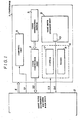
- Fig. 1 is a schematic block diagram showing a bank note cartridge 1 and the main body 2 of a bank note dispensing machine, together incorporating said preferred embodiment of the bank note cartridge identification system according to the present invention; and in this figure the internal structure of the bank note cartridge 1 is schematically shown in a block diagrammatical form.
- the activation of this bank note cartridge 1 is commenced when it is physically inserted into the main body 2 of the bank note dispensing machine and receives a supply of electrical energy therefrom as shown by "E" in Fig. I; and the bank note cartridge 1 comprises a code generating switch 3, a code conversion unit 4, and a control unit 5.
- the code generating switch 3 is for setting up an attendance code; the code conversion unit 4 is for converting the code set up on the code generating switch 3 into a code signal 52 and sending this code signal S2 to the main body 2 of the bank note dispensing machine; and the control unit 5 is for controlling the code generating switch 3 and the code conversion unit 4. Further, the control unit 5 is operated by receiving a control signal S1 from the main body 2 of the bank note dispensing machine, when as explained above the bank note cartridge 1 is physically inserted into said main body 2 of the bank note dispensing machine.
- the bank note cartridge 1 there is provided a bank note storage unit 9 in which bank notes are put and stored, and the take out side of this bank note storage unit 9 is provided with a note take out sensor 10 which detects when a bank note or notes is or are taken out of the bank note storage unit 9 and produces an output signal S4 indicative thereof which is sent to the main body 2 of the bank note dispensing machine.
- the bank note cartridge 1 further comprises a take out unit 6 for taking out bank notes from this bank note storage unit 9, which comprises a clutch 7 for a take out roller not shown in the drawings, and a brake 8. The clutch 7 and the clutch brake 8 are turned ON and OFF according to a control signal S3 which is dispatched from the main body 2 of the bank note dispensing machine.
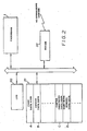
- Fig. 2 shows in schematic form the internal struct re of the main body 2 of the bank note dispening machine.
- a control unit thereof comprises a microcomputer system comprising a CPU 20 and a memory means 21, which are interconnected via a common bus. And via this common bus the CPU 20 and the memory means 1 are interconnected with the cartridge 1 for the bank note dispenser, for the transmission of the signals Sl, S2, S3, and S4 of Fig. 1 therebetween, said bank note cartridg 1 being connected to said bus when said bank note cartridge 1 is fitted into the bank note dispenser.
- a modem 22 is connected to the common bus, and its other side is connected via a transmission line with an operations center (not illustrated in the figures) which controls the operation of this bank note dispensing machine among others.
- the area A is used as a code data area for storing attendance code data as dispatched from the code conversion unit 4; the area B is used as an output data area for data from the note take out sensor 10; the area C is used as a operations center directions data area for storing data representing instructions from the operations center as dispatched from said operations center via the modem 22; and the area D is used as a banknote number data area for storing data representing the number of banknotes to be dispensed to the current user of the bank note dispenser machine, as dispatched from the operations center via the modem 22.
- the operations center maintains a file of data for managing the numbers and denominations of bank notes in each of the cartridges in each of the bank note dispenser machines which are managed by the center.
- the main body 2 of the bank note dispensing machine is provided with a CR T display for displaying operating instructions and results, facing towards the customer of the bank note dispensing machine, but this is not particularly shown in the figures.
- an attendant sets up a particular attendance code for the cartridge 1 by setting it using the code generating switch 3.
- This particular attendance code may have any of a variety of particular significances, but typically will specify a particular episode of charging of the cartridge 1, and this episode will be associated in the abovementioned file kept by the operations center with a particular target bank note dispensing machine for fitting of this cartridge 1, with a particular denomination of bank note and number of such bank notes charged into the cartridge 1, and so on.
- the operations center will be apprised of all necessary data about the cartridge 1.
- the cartridge 1 typically is removed from the operations center and is conveyed under guard to the vicinity of the particular bank note dispensing machine for which it is destined; and said cartridge 1 is then physically inserted into the main body 2 of said appropriate bank note dispensing machine and receives a supply of electrical energy therefrom as shown by "E" in Fig. 1.
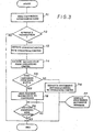
- the operation of the program illustrated in Fig. 3 is started, in the START block.
- the first thing that now happens is that the CPU 20 outputs a command signal Sl to the control unit 5 which causes it to so control the code generating switch 3 and the code conversion unit 4 that the aforesaid attendance data set up by the code generating switch 3 are processed by the code conversion unit 4 and are converted to a code signal S2 which is dispatched from the cartridge 1 to the main body 2 of the bank note dispensing machine, and the data in this code signal 5 2 is received by the C PU 20 and is stored in the area A of the memory means 21; this step is denoted by the step nl of the Fig. 3 flow chart.
- step n2 a test is made as to whether or not a transaction is present; if not, the program terminates, but if a transaction is ready to be processed then the designation of the dispensing transaction for the customer and the inputting of the sum of money to be dispensed in the form of bank notes are performed, and thus the transaction process is executed.
- step n3 communications are initiated with the operations center and the above information is dispatched thereto; and next in the step n4 information is received from the operations center: a cartridge code for the denominations corresponding to the sum to be dispensed to the customer of the bank note dispensing machine, and data relating to the number of bank notes to be so dispensed for each of the cartridges.
- the cartridge code data designated by the operations center is stored in the area C of the memory means 21, while the number of bank notes to be dispensed designated by the operations center is stored in the area D of the memory means 21.
- step n5 matching is made by the CPU 20 of the cartridge code data.
- the CPU 20 determines whether or not the cartridge designated by the center is loaded into the bank note dispenser machine.
- the flow of control passes to the step n6, in which a signal is dispatched to the operation center informing said operation center of this situation, and next the flow of control passes to the step n7, in which a "processing impossible" message is displayed on the CRT display (not shown) in order to inform the customer that dispensation of bank notes is impossible; and then the opration of the Fig. 3 program is terminated.
- the cartridge which is loaded is the one designated by the center, i.e. the cartridge designated by the center is loaded, i.e. if the result of the test in the decision block n5 is YES, then it is determined that it is in fact possible to continue with the processing of the dispensation of bank notes to the customer, and the flow of control passes to the step n8, in which appropriate signals S3 are dispatched to the clutch 7 and to the brake 8 of the take out unit 6 of the cartridge 1 for taking out the appropriate number of bank notes from the bank note storage unit 9; this appropriate number is the number of bank notes recorded in the area D of the memory means 21 of the bank note dispensing machine control system.
- step n9 in which a test is made as to whether the bank note dispensing operation by said take out unit 6 has been completed or not, which is ascertained according to the signals S4 received from the note take out sensor 10 provided to the bank note storage unit 9, which indicate the actual taking out of each bank note in an ongoing manner. Track of these output signals is kept by using the area B of the memory means 21 of the bank note dispensing machine control system.
- step n9 until the count of the dispensed bank notes is completed, the program loops back; and on the other hand, when said count of the dispensed bank notes is completed, so that the appropriate number of banknotes has definitely been dispensed to the customer, the flow of control passes to the END block of the Fig. 3 program.
- each bank note cartridge which is to be used in this system by the use of its code setting means, a unique code, and this code can include information such as an attendance code, a cartridge serial number, and so on.
- the generating means generates a signal representative of this code and sends it to the bank note dispensing machine.
- the checking means checks this signal and verifies that the code set to this bank note cartridge is correct, i.e. that the correct and appropriate bank note cartridge has been charged to the bank note dispensing machine.
Abstract
Description
- The present invention relates to a bank note cartridge identification system for a bank note dispensing machine such as an automatic teller machine and a bank note cartridge or cartridges which are to be fitted thereto, and in particular relates to such a bank note cartridge identification system which can keep good track of various bank note cartridges and can check that the correct cartridge or cartridges is fitted to such a bank note dispensing machine, at all times.
- Conventionally, bank note dispensing machines such as automatic teller machines and the like are replenished with bank notes by being charged with cartridges which are themselves beforehand loaded with bank notes at an operations center or some such place where security is excellent. And typically in fact such a bank note dispensing machine is charged with a different cartridge for each denomination of notes which it dispenses. However, since a conventional such cartridge for bank notes does not show on its outside the various details relating to it, such as how many bank notes it is currently charged with, their denomination, and for what automatic bank note dispensing machine (out of a plurality of automatic bank note dispensing machines typically handled by the operations center) said bank note cartridge is destined, the problem arises that, when various bank note cartridges are being distributed from such an operations center for being charged to various different automatic bank note dispensing machines, it is difficult to identify which cartridge to charge to which bank note dispensing machine, and mistakes are liable to occur with the charging process. Such mistakes can lead to serious lapses of security, and provide a fertile ground for fraud, waste, and abuse. Further, if a cartrige should happen to be lost in transit, as after being removed from a bank note dispensing machine, it cannot be readily determined which cartridge has been lost.
- Accordingly, it is the primary object of the present invention to provide a bank note cartridge - identification system which can overcome the above identified problems.
- It is a further object of the present invention to provide such a bank note cartridge identification system which can reliably match bank note cartridges with the appropriate,bank note dispensing machine for which they are destined.
- It is a further object of the present invention to provide such a bank note cartridge identification system which ensures that if a bank note cartridge is lost after being removed from a bank note dispensing machine it is possible easily to determine which such bank note cartridge has been lost.
- It is a yet further object of the present invention to provide such a bank note cartridge identification system which can help to prevent waste.
- It is a yet further object of the present invention to provide such a bank note cartridge identification system which improves protection against fraud.
- It is a yet further object of the present invention to provide such a bank note cartridge identification system which provides good security.
- According to the most general aspect of the present invention, these and other objects are accomplished by a bank note cartridge identification system, for a bank note dispensing machine and a bank note cartridge which can be fitted to said bank note dispensing machine, comprising: (a) a means, incorporated in said bank note cartridge, for setting an identification code; (b) a means, incorporated in said bank note cartridge, for generating a signal representative of said identification code set by said setting means and for transmitting it to said bank note dispensing machine, when said bank note cartridge is fitted to said bank note dispensing machine; and (c) a means, incorporated in said bank note dispensing machine, for checking said signal, outputted by said generating means, representative of said identification code set by said setting means.
- According to such a structure, it is possible to set on each bank note cartridge which is to be used in this system, by the use of its above defined code setting means, a unique code, and this code can include information such as an attendance code, a cartridge serial number, and so on. And when a bank note cartridge is charged to the bank note dispensing machine, then the generating means generates a signal representative of this code and sends it to the bank note dispensing machine. And in the bank note dispensing machine the checking means then checks this signal and verifies that the code set to this bank note cartridge is correett, i.e. that the correct and appropriate bank note cartridge has been charged to the bank note dispensing machine. As a result, a considerable improvement can be made in terms of handling and security by allowing reliable identification of the charged cartridge from the side of the bank note dispenser and by aiding with the instantaneous determination of any lost cartridge which may have been lost in transit. Thus, fraud, waste, and abuse are made very difficult.
- Further, according to a more particular aspect of the present invention, these and other objects are more particularly and concretely accomplished by such a bank note cartridge identification system as described above, wherein said checking means comprises a means for communicating with a distant center for verifying the validity of said identification code set to said bank note cartridge. by said setting means.
- According to such a structure, this distant operations center can keep track of the proper bank note cartridges to be fitted to a plurality of bank note dispensing machines, and can receive and provide the information necessary for up to the minute checking of each bank note cartridge charged to each of these bank note dispensing machines. Thus, mistakes in the charging of the bank note dispensing machines are kept to a minimum.
- The present invention will now be shown and described with reference to the preferred embodiment thereof, and with reference to the illustrative drawings. It should be clearly understood, however, that the description of the embodiment, and the drawings, are all of them given purely for the purposes of explanation and exemplification only, and are none of them intended to be limitative of the scope of the present invention in any way, since the scope of the present invention is to be defined solely by the legitimate and proper scope of the appended claims. In the drawings, like parts and spaces and so on are denoted by like reference symbols in the various figures thereof, and:
-
- Fig. 1 is a schematic block diagram showing the main body of a bank note dispensing machine and in block diagrammatical form the internal structure of a bank note cartridge therefor, these together incorporating said preferred embodiment of the bank note cartridge identification system' according to the present invention;
- Fig. 2 is a schematic block diagram showing part of the internal structure of a control system for the bank note dispensing machine, and also showing the cartridge; and
- Fig. 3 is a flow chart illustrating the operation of a program stored in a microcomputer incorporated in the control system illustrated in Fig. 2, for explaining the operation of the bank note cartridge identification system according to the present invention.
- The present invention will now be described with reference to the preferred embodiment thereof, and with reference to the appended drawings. Fig. 1 is a schematic block diagram showing a
bank note cartridge 1 and themain body 2 of a bank note dispensing machine, together incorporating said preferred embodiment of the bank note cartridge identification system according to the present invention; and in this figure the internal structure of thebank note cartridge 1 is schematically shown in a block diagrammatical form. The activation of thisbank note cartridge 1 is commenced when it is physically inserted into themain body 2 of the bank note dispensing machine and receives a supply of electrical energy therefrom as shown by "E" in Fig. I; and thebank note cartridge 1 comprises acode generating switch 3, acode conversion unit 4, and a control unit 5. Thecode generating switch 3 is for setting up an attendance code; thecode conversion unit 4 is for converting the code set up on thecode generating switch 3 into a code signal 52 and sending this code signal S2 to themain body 2 of the bank note dispensing machine; and the control unit 5 is for controlling thecode generating switch 3 and thecode conversion unit 4. Further, the control unit 5 is operated by receiving a control signal S1 from themain body 2 of the bank note dispensing machine, when as explained above thebank note cartridge 1 is physically inserted into saidmain body 2 of the bank note dispensing machine. - Moreover, within the
bank note cartridge 1 there is provided a bank note storage unit 9 in which bank notes are put and stored, and the take out side of this bank note storage unit 9 is provided with a note take outsensor 10 which detects when a bank note or notes is or are taken out of the bank note storage unit 9 and produces an output signal S4 indicative thereof which is sent to themain body 2 of the bank note dispensing machine. And thebank note cartridge 1 further comprises a take out unit 6 for taking out bank notes from this bank note storage unit 9, which comprises a clutch 7 for a take out roller not shown in the drawings, and abrake 8. The clutch 7 and theclutch brake 8 are turned ON and OFF according to a control signal S3 which is dispatched from themain body 2 of the bank note dispensing machine. - Fig. 2 shows in schematic form the internal struct re of the
main body 2 of the bank note dispening machine. A control unit thereof comprises a microcomputer system comprising aCPU 20 and a memory means 21, which are interconnected via a common bus. And via this common bus theCPU 20 and the memory means 1 are interconnected with thecartridge 1 for the bank note dispenser, for the transmission of the signals Sl, S2, S3, and S4 of Fig. 1 therebetween, saidbank note cartridg 1 being connected to said bus when saidbank note cartridge 1 is fitted into the bank note dispenser. Further, amodem 22 is connected to the common bus, and its other side is connected via a transmission line with an operations center (not illustrated in the figures) which controls the operation of this bank note dispensing machine among others. - In the
memory 21 there are areas A, B, C, and D. The area A is used as a code data area for storing attendance code data as dispatched from thecode conversion unit 4; the area B is used as an output data area for data from the note take outsensor 10; the area C is used as a operations center directions data area for storing data representing instructions from the operations center as dispatched from said operations center via themodem 22; and the area D is used as a banknote number data area for storing data representing the number of banknotes to be dispensed to the current user of the bank note dispenser machine, as dispatched from the operations center via themodem 22. - Although it is not so shown in the drawings, the operations center maintains a file of data for managing the numbers and denominations of bank notes in each of the cartridges in each of the bank note dispenser machines which are managed by the center. Also, the
main body 2 of the bank note dispensing machine is provided with a CRT display for displaying operating instructions and results, facing towards the customer of the bank note dispensing machine, but this is not particularly shown in the figures. - Next, the operation of the preferred embodiment of the bank note cartridge identification system according to the present invention, and the operation of this bank note dispensing machine when it is loaded with the
cartridge 1, will be explained, with reference to the flow chart shown in Fig. 3 of the operation of the microcomputer shown in Fig. 2. - Initially, when the
cartridge 1 is separate from themain body 2 of the bank note dispensing machine, typically at the time that it is being charged with a new supply of bank notes which may be performed at the operations center, an attendant sets up a particular attendance code for thecartridge 1 by setting it using thecode generating switch 3. This particular attendance code may have any of a variety of particular significances, but typically will specify a particular episode of charging of thecartridge 1, and this episode will be associated in the abovementioned file kept by the operations center with a particular target bank note dispensing machine for fitting of thiscartridge 1, with a particular denomination of bank note and number of such bank notes charged into thecartridge 1, and so on. Thus, when provided with the particular attendance code set up for thecartridge 1, the operations center will be apprised of all necessary data about thecartridge 1. - Next, the
cartridge 1 typically is removed from the operations center and is conveyed under guard to the vicinity of the particular bank note dispensing machine for which it is destined; and saidcartridge 1 is then physically inserted into themain body 2 of said appropriate bank note dispensing machine and receives a supply of electrical energy therefrom as shown by "E" in Fig. 1. At this time, the operation of the program illustrated in Fig. 3 is started, in the START block. - The first thing that now happens is that the
CPU 20 outputs a command signal Sl to the control unit 5 which causes it to so control thecode generating switch 3 and thecode conversion unit 4 that the aforesaid attendance data set up by thecode generating switch 3 are processed by thecode conversion unit 4 and are converted to a code signal S2 which is dispatched from thecartridge 1 to themain body 2 of the bank note dispensing machine, and the data in thiscode signal 52 is received by theC PU 20 and is stored in the area A of the memory means 21; this step is denoted by the step nl of the Fig. 3 flow chart. - Next, in the step n2, a test is made as to whether or not a transaction is present; if not, the program terminates, but if a transaction is ready to be processed then the designation of the dispensing transaction for the customer and the inputting of the sum of money to be dispensed in the form of bank notes are performed, and thus the transaction process is executed.
- Next, in the step n3, communications are initiated with the operations center and the above information is dispatched thereto; and next in the step n4 information is received from the operations center: a cartridge code for the denominations corresponding to the sum to be dispensed to the customer of the bank note dispensing machine, and data relating to the number of bank notes to be so dispensed for each of the cartridges. The cartridge code data designated by the operations center is stored in the area C of the memory means 21, while the number of bank notes to be dispensed designated by the operations center is stored in the area D of the memory means 21.
- Next, in the step n5, matching is made by the
CPU 20 of the cartridge code data. In other words, by determination of matching or not matching of the code data in the area A of the memory means 21 with the code data in the area C thereof, it is determined whether or not the cartridge designated by the center is loaded into the bank note dispenser machine. - If the cartridge which is loaded is not the one designated by the center, or the cartridge designated by the center is not loaded, i.e. if the result of the test in the decision block n5 is NO, then it is determined that it is impossible to continue with the processing of the dispensation of bank notes to the customer, and the flow of control passes to the step n6, in which a signal is dispatched to the operation center informing said operation center of this situation, and next the flow of control passes to the step n7, in which a "processing impossible" message is displayed on the CRT display (not shown) in order to inform the customer that dispensation of bank notes is impossible; and then the opration of the Fig. 3 program is terminated.
- On the other hand, if the cartridge which is loaded is the one designated by the center, i.e. the cartridge designated by the center is loaded, i.e. if the result of the test in the decision block n5 is YES, then it is determined that it is in fact possible to continue with the processing of the dispensation of bank notes to the customer, and the flow of control passes to the step n8, in which appropriate signals S3 are dispatched to the clutch 7 and to the
brake 8 of the take out unit 6 of thecartridge 1 for taking out the appropriate number of bank notes from the bank note storage unit 9; this appropriate number is the number of bank notes recorded in the area D of the memory means 21 of the bank note dispensing machine control system. Next, the flow of control passes to the step n9, in which a test is made as to whether the bank note dispensing operation by said take out unit 6 has been completed or not, which is ascertained according to the signals S4 received from the note take outsensor 10 provided to the bank note storage unit 9, which indicate the actual taking out of each bank note in an ongoing manner. Track of these output signals is kept by using the area B of the memory means 21 of the bank note dispensing machine control system. In this step n9, until the count of the dispensed bank notes is completed, the program loops back; and on the other hand, when said count of the dispensed bank notes is completed, so that the appropriate number of banknotes has definitely been dispensed to the customer, the flow of control passes to the END block of the Fig. 3 program. - By this operation, therefore, dispensation of the appropriate number of bank notes corresponding to the sum to be dispensed to the customer of the bank note dispensing machine is performed from the
cartridge 1, for which the attendance code is set up on thecode generation switch 3. In other words, because the attendance code can be arbitrarily and appropriately set up for thecartridge 1, and because the checking of the code on thecartridge 1 is performed as explained above when thecartridge 1 is loaded into themain body 2 of the bank note dispensing machine, it becomes possible for the operations center to manage the bank note cartridges for each of the codes, for a plurality of various bank note dispensing machines if need be, and the management of these bank note dispensing machines is made smoother with additional advantages relating to the improvement of security. - Thus it is seen that according to the shown structure it is possible to set on each bank note cartridge which is to be used in this system, by the use of its code setting means, a unique code, and this code can include information such as an attendance code, a cartridge serial number, and so on. And when a bank note cartridge is charged to the bank note dispensing machine, then the generating means generates a signal representative of this code and sends it to the bank note dispensing machine. And in the bank note dispensing machine the checking means then checks this signal and verifies that the code set to this bank note cartridge is correct, i.e. that the correct and appropriate bank note cartridge has been charged to the bank note dispensing machine. As a result, a considerable improvement can be made in terms of handling and security by allowing reliable identification of the charged cartridge from the side of the bank note dispenser and by aiding with the instantaneous determination of any lost cartridge which may have been lost in transit. Thus, fraud, waste, and abuse are made very difficult.
- Although the present invention has been shown and described with reference to the preferred embodiment thereof, and in terms of the illustrative drawings, it should not be considered as limited thereby. Various possible modifications, omissions, and alterations could be conceived of by one skilled in the art to the form and the content of any particular embodiment, without departing from the scope of the present invention. For example, although in the above described preferred embodiment the code set for the cartridge was an attendance code, in other possible embodiments the code could be of some other sort, as long as it is an indication code which is required by the operations center for managing the cartridge: this code could be a cartridge serial number, for instance. Other modifications are also possible. Therefore it is desired that the scope of the present invention, and of the protection sought to be granted by Letters Patent, should be defined not by any of the perhaps purely fortuitous details of the shown preferred embodiment, or of the drawings, but solely by the scope of the appended claims, which follow.
Claims (3)
Applications Claiming Priority (2)
| Application Number | Priority Date | Filing Date | Title |
|---|---|---|---|
| JP120929/84 | 1984-06-11 | ||
| JP59120929A JPS60262736A (en) | 1984-06-11 | 1984-06-11 | Cartridge for bank note dispenser |
Publications (2)
| Publication Number | Publication Date |
|---|---|
| EP0164733A2 true EP0164733A2 (en) | 1985-12-18 |
| EP0164733A3 EP0164733A3 (en) | 1987-10-21 |
Family
ID=14798465
Family Applications (1)
| Application Number | Title | Priority Date | Filing Date |
|---|---|---|---|
| EP85107204A Ceased EP0164733A3 (en) | 1984-06-11 | 1985-06-11 | Bank note cartridge identification system for cash dispensor |
Country Status (3)
| Country | Link |
|---|---|
| US (1) | US4808801A (en) |
| EP (1) | EP0164733A3 (en) |
| JP (1) | JPS60262736A (en) |
Cited By (12)
| Publication number | Priority date | Publication date | Assignee | Title |
|---|---|---|---|---|
| EP0307375A2 (en) * | 1987-08-11 | 1989-03-15 | Inter Innovation AB | A system for transferring quickly and reliably to a centrally located monetary institution at least the value of valuable documents |
| EP0355238A1 (en) * | 1988-08-25 | 1990-02-28 | Scheidt & Bachmann Gmbh | Assembly of a plurality of product or service vending machines |
| EP0493127A2 (en) * | 1990-12-28 | 1992-07-01 | Fujitsu Limited | Cash processing system |
| US5321242A (en) * | 1991-12-09 | 1994-06-14 | Brinks, Incorporated | Apparatus and method for controlled access to a secured location |
| US5451757A (en) * | 1990-04-22 | 1995-09-19 | Brink's Incorporated | Apparatus and method for controlled access to a secured location |
| WO2003100735A1 (en) | 2002-05-27 | 2003-12-04 | Japan Cash Machine Co., Ltd. | Bill handling device |
| WO2011067374A1 (en) * | 2009-12-04 | 2011-06-09 | Wincor Nixdorf International Gmbh | Device for handling value documents |
| US8967361B2 (en) | 2013-02-27 | 2015-03-03 | Outerwall Inc. | Coin counting and sorting machines |
| US9022841B2 (en) | 2013-05-08 | 2015-05-05 | Outerwall Inc. | Coin counting and/or sorting machines and associated systems and methods |
| US9036890B2 (en) | 2012-06-05 | 2015-05-19 | Outerwall Inc. | Optical coin discrimination systems and methods for use with consumer-operated kiosks and the like |
| US9235945B2 (en) | 2014-02-10 | 2016-01-12 | Outerwall Inc. | Coin input apparatuses and associated methods and systems |
| EP2324462B1 (en) * | 2008-09-03 | 2016-05-11 | Wincor Nixdorf International GmbH | Arrangement and method for preventing manipulations on a transport container for notes of value |
Families Citing this family (10)
| Publication number | Priority date | Publication date | Assignee | Title |
|---|---|---|---|---|
| US5099423A (en) * | 1985-06-27 | 1992-03-24 | Diebold, Incorporated | Method and apparatus for account settlement in an ATM |
| JPS62184591A (en) * | 1986-02-10 | 1987-08-12 | オムロン株式会社 | Automatic cash transaction processor |
| US5695038A (en) * | 1995-07-24 | 1997-12-09 | Brink's, Incorporated | Drop safe |
| US6067530A (en) * | 1995-10-13 | 2000-05-23 | Brooks Armored Car Services, Inc. | Cash management system |
| US6822550B1 (en) | 1998-01-12 | 2004-11-23 | At Systems, Inc. | Intelligent rolled coin dispenser |
| US6003008A (en) * | 1998-03-20 | 1999-12-14 | Skyteller L.L.C. | Point of sale device |
| JP4372919B2 (en) * | 1999-10-26 | 2009-11-25 | 富士通株式会社 | Automatic cash transaction apparatus and method |
| JP3999476B2 (en) * | 2001-06-21 | 2007-10-31 | 日立オムロンターミナルソリューションズ株式会社 | Banknote handling equipment |
| DE102005037343A1 (en) * | 2005-08-04 | 2007-02-15 | Wincor Nixdorf International Gmbh | System for entering and issuing notes of value |
| EP1832632A1 (en) | 2006-03-07 | 2007-09-12 | DSM IP Assets B.V. | Conductive ink |
Citations (5)
| Publication number | Priority date | Publication date | Assignee | Title |
|---|---|---|---|---|
| US3833885A (en) * | 1973-05-24 | 1974-09-03 | Docutel Corp | Automatic banking system |
| FR2443405A1 (en) * | 1978-12-08 | 1980-07-04 | De La Rue Syst | CASSETTE FOR BANKNOTES |
| EP0030413A1 (en) * | 1979-11-29 | 1981-06-17 | Leif Lundblad | A system for the handling of documents within a monetary establishment |
| EP0004436B1 (en) * | 1978-03-21 | 1981-07-22 | Leif Lundblad | An arrangement for handling banknotes or the like |
| US4380316A (en) * | 1981-07-14 | 1983-04-19 | Qonaar Corporation | Electronic interlock for a cash collection receptacle |
Family Cites Families (7)
| Publication number | Priority date | Publication date | Assignee | Title |
|---|---|---|---|---|
| JPS56111967A (en) * | 1980-02-07 | 1981-09-04 | Omron Tateisi Electronics Co | Transaction process system |
| US4437660A (en) * | 1981-11-16 | 1984-03-20 | Datapoint Corporation | Word processor--controlled printer output scanner mechanism |
| JPS5887692A (en) * | 1981-11-20 | 1983-05-25 | オムロン株式会社 | Transaction processor |
| JPS58138340U (en) * | 1982-03-15 | 1983-09-17 | 黒谷 信子 | Carrier for cleaning and etching wafers |
| US4650977A (en) * | 1983-12-21 | 1987-03-17 | International Business Machines Corporation | Automatic self service machine system and method |
| US4577763A (en) * | 1984-03-28 | 1986-03-25 | Ncr Corporation | Cash dispensing system |
| GB2165383B (en) * | 1984-10-03 | 1988-05-25 | Ncr Co | Data sensing system for currency cassettes |
-
1984
- 1984-06-11 JP JP59120929A patent/JPS60262736A/en active Pending
-
1985
- 1985-06-10 US US06/743,151 patent/US4808801A/en not_active Expired - Lifetime
- 1985-06-11 EP EP85107204A patent/EP0164733A3/en not_active Ceased
Patent Citations (5)
| Publication number | Priority date | Publication date | Assignee | Title |
|---|---|---|---|---|
| US3833885A (en) * | 1973-05-24 | 1974-09-03 | Docutel Corp | Automatic banking system |
| EP0004436B1 (en) * | 1978-03-21 | 1981-07-22 | Leif Lundblad | An arrangement for handling banknotes or the like |
| FR2443405A1 (en) * | 1978-12-08 | 1980-07-04 | De La Rue Syst | CASSETTE FOR BANKNOTES |
| EP0030413A1 (en) * | 1979-11-29 | 1981-06-17 | Leif Lundblad | A system for the handling of documents within a monetary establishment |
| US4380316A (en) * | 1981-07-14 | 1983-04-19 | Qonaar Corporation | Electronic interlock for a cash collection receptacle |
Cited By (29)
| Publication number | Priority date | Publication date | Assignee | Title |
|---|---|---|---|---|
| EP0307375A3 (en) * | 1987-08-11 | 1990-02-28 | Inter Innovation AB | A system for transferring quickly and reliably to a centrally located monetary institution at least the value of valuable documents |
| EP0307375A2 (en) * | 1987-08-11 | 1989-03-15 | Inter Innovation AB | A system for transferring quickly and reliably to a centrally located monetary institution at least the value of valuable documents |
| EP0355238A1 (en) * | 1988-08-25 | 1990-02-28 | Scheidt & Bachmann Gmbh | Assembly of a plurality of product or service vending machines |
| US5056643A (en) * | 1988-08-25 | 1991-10-15 | Scheidt & Bachmann Gesellschaft Mit Beschrankter Haftung | Method for recording the placement of replaceable, self-filling coin-storing units |
| US5451757A (en) * | 1990-04-22 | 1995-09-19 | Brink's Incorporated | Apparatus and method for controlled access to a secured location |
| US6523742B1 (en) | 1990-12-28 | 2003-02-25 | Fujitsu Limited | Cash processing system for automatically performing cash handling with limited operator handling of cash |
| EP0493127A3 (en) * | 1990-12-28 | 1993-03-03 | Fujitsu Limited | Cash processing system |
| EP0718810A2 (en) * | 1990-12-28 | 1996-06-26 | Fujitsu Limited | Cash handling apparatus |
| EP0718810A3 (en) * | 1990-12-28 | 1996-07-24 | Fujitsu Ltd | |
| US5606157A (en) * | 1990-12-28 | 1997-02-25 | Fujitsu Limited | Cash processing system for automatically performing cash handling operations associated with banking services |
| US5777304A (en) * | 1990-12-28 | 1998-07-07 | Fujitsu Limited | Cash processing system for automatically performing cash handling operations associated with banking services |
| US5864826A (en) * | 1990-12-28 | 1999-01-26 | Fujitsu Limited | Cash processing system for handling unretrieved cash |
| US5900607A (en) * | 1990-12-28 | 1999-05-04 | Fujitsu Limited | Cash processing system for automatically performing cash handling operations associated with banking services |
| EP0493127A2 (en) * | 1990-12-28 | 1992-07-01 | Fujitsu Limited | Cash processing system |
| US5321242A (en) * | 1991-12-09 | 1994-06-14 | Brinks, Incorporated | Apparatus and method for controlled access to a secured location |
| EP1510978A1 (en) * | 2002-05-27 | 2005-03-02 | Japan Cash Machine Co., Ltd. | Bill handling device |
| WO2003100735A1 (en) | 2002-05-27 | 2003-12-04 | Japan Cash Machine Co., Ltd. | Bill handling device |
| EP1510978A4 (en) * | 2002-05-27 | 2007-08-01 | Nippon Kinsen Kikai Kk | Bill handling device |
| EP2324462B1 (en) * | 2008-09-03 | 2016-05-11 | Wincor Nixdorf International GmbH | Arrangement and method for preventing manipulations on a transport container for notes of value |
| WO2011067374A1 (en) * | 2009-12-04 | 2011-06-09 | Wincor Nixdorf International Gmbh | Device for handling value documents |
| CN102792342A (en) * | 2009-12-04 | 2012-11-21 | 德利多富国际有限责任公司 | Device for handling value documents |
| US8869966B2 (en) | 2009-12-04 | 2014-10-28 | Wincor Nixdorf International Gmbh | Device for handling value documents |
| US9379464B2 (en) | 2009-12-04 | 2016-06-28 | Wincor Nixdorf International Gmbh | Device for handling value documents |
| CN102792342B (en) * | 2009-12-04 | 2015-07-01 | 德利多富国际有限责任公司 | Device for handling value documents |
| US9036890B2 (en) | 2012-06-05 | 2015-05-19 | Outerwall Inc. | Optical coin discrimination systems and methods for use with consumer-operated kiosks and the like |
| US9230381B2 (en) | 2013-02-27 | 2016-01-05 | Outerwall Inc. | Coin counting and sorting machines |
| US8967361B2 (en) | 2013-02-27 | 2015-03-03 | Outerwall Inc. | Coin counting and sorting machines |
| US9022841B2 (en) | 2013-05-08 | 2015-05-05 | Outerwall Inc. | Coin counting and/or sorting machines and associated systems and methods |
| US9235945B2 (en) | 2014-02-10 | 2016-01-12 | Outerwall Inc. | Coin input apparatuses and associated methods and systems |
Also Published As
| Publication number | Publication date |
|---|---|
| EP0164733A3 (en) | 1987-10-21 |
| US4808801A (en) | 1989-02-28 |
| JPS60262736A (en) | 1985-12-26 |
Similar Documents
| Publication | Publication Date | Title |
|---|---|---|
| US4808801A (en) | Bank note cartridge identification system for cash dispenser | |
| US6523742B1 (en) | Cash processing system for automatically performing cash handling with limited operator handling of cash | |
| US6378770B1 (en) | Automated teller machines and method of replenishing the same | |
| US4314352A (en) | Banking machine | |
| EP2101301B1 (en) | Paper currency handling apparatus and automated teller machine | |
| US4225779A (en) | Banking apparatus and method | |
| US20020107800A1 (en) | Automated teller machine and centralized managing system | |
| US7036722B2 (en) | Automatic transaction machine | |
| US4249163A (en) | Automatic money dispenser and method | |
| CN102087764B (en) | Automatic transaction processing apparatus and automatic transaction processing system | |
| US4511794A (en) | System for performing transactions | |
| CN102346927B (en) | Paper sheet identifying apparatus | |
| US9640007B2 (en) | Medium transaction device | |
| EP1271425A2 (en) | Bill handling machine | |
| CN103514660B (en) | Currency processing unit and device for automatic processing of transactions | |
| US4546240A (en) | System for performing transactions | |
| CN110852613A (en) | Banknote adding method, device, equipment and medium | |
| EP0005941A1 (en) | Teller machines and methods of operation thereof | |
| JP4403725B2 (en) | Cash processing system and program thereof | |
| JP5255458B2 (en) | Banknote transaction device and banknote transaction system | |
| JP7405631B2 (en) | Money processing device, money processing system, and money processing method | |
| JPH0351030B2 (en) | ||
| CN106652250A (en) | Automatic transaction system and automatic account checking method thereof | |
| JPS5945580A (en) | Transaction processing device | |
| JPH0379749B2 (en) |
Legal Events
| Date | Code | Title | Description |
|---|---|---|---|
| PUAI | Public reference made under article 153(3) epc to a published international application that has entered the european phase |
Free format text: ORIGINAL CODE: 0009012 |
|
| 17P | Request for examination filed |
Effective date: 19850611 |
|
| AK | Designated contracting states |
Designated state(s): AT BE CH DE FR GB IT LI LU NL SE |
|
| PUAL | Search report despatched |
Free format text: ORIGINAL CODE: 0009013 |
|
| AK | Designated contracting states |
Kind code of ref document: A3 Designated state(s): AT BE CH DE FR GB IT LI LU NL SE |
|
| 17Q | First examination report despatched |
Effective date: 19880105 |
|
| STAA | Information on the status of an ep patent application or granted ep patent |
Free format text: STATUS: THE APPLICATION HAS BEEN REFUSED |
|
| 18R | Application refused |
Effective date: 19920525 |
|
| RIN1 | Information on inventor provided before grant (corrected) |
Inventor name: NAKAGAWA, MASAKATZSUC/O OMRON TATEISI ELEC. CO. |