EP0171275A2 - Carton and blank therefor of polymeric material - Google Patents
Carton and blank therefor of polymeric material Download PDFInfo
- Publication number
- EP0171275A2 EP0171275A2 EP85305533A EP85305533A EP0171275A2 EP 0171275 A2 EP0171275 A2 EP 0171275A2 EP 85305533 A EP85305533 A EP 85305533A EP 85305533 A EP85305533 A EP 85305533A EP 0171275 A2 EP0171275 A2 EP 0171275A2
- Authority
- EP
- European Patent Office
- Prior art keywords
- carton
- blank
- flaps
- panels
- fold lines
- Prior art date
- Legal status (The legal status is an assumption and is not a legal conclusion. Google has not performed a legal analysis and makes no representation as to the accuracy of the status listed.)
- Granted
Links
Images


Classifications
-
- B—PERFORMING OPERATIONS; TRANSPORTING
- B65—CONVEYING; PACKING; STORING; HANDLING THIN OR FILAMENTARY MATERIAL
- B65D—CONTAINERS FOR STORAGE OR TRANSPORT OF ARTICLES OR MATERIALS, e.g. BAGS, BARRELS, BOTTLES, BOXES, CANS, CARTONS, CRATES, DRUMS, JARS, TANKS, HOPPERS, FORWARDING CONTAINERS; ACCESSORIES, CLOSURES, OR FITTINGS THEREFOR; PACKAGING ELEMENTS; PACKAGES
- B65D5/00—Rigid or semi-rigid containers of polygonal cross-section, e.g. boxes, cartons or trays, formed by folding or erecting one or more blanks made of paper
- B65D5/42—Details of containers or of foldable or erectable container blanks
- B65D5/4279—Joints, seams, leakproof joints or corners, special connections between panels
-
- B—PERFORMING OPERATIONS; TRANSPORTING
- B65—CONVEYING; PACKING; STORING; HANDLING THIN OR FILAMENTARY MATERIAL
- B65D—CONTAINERS FOR STORAGE OR TRANSPORT OF ARTICLES OR MATERIALS, e.g. BAGS, BARRELS, BOTTLES, BOXES, CANS, CARTONS, CRATES, DRUMS, JARS, TANKS, HOPPERS, FORWARDING CONTAINERS; ACCESSORIES, CLOSURES, OR FITTINGS THEREFOR; PACKAGING ELEMENTS; PACKAGES
- B65D5/00—Rigid or semi-rigid containers of polygonal cross-section, e.g. boxes, cartons or trays, formed by folding or erecting one or more blanks made of paper
- B65D5/42—Details of containers or of foldable or erectable container blanks
- B65D5/72—Contents-dispensing means
- B65D5/74—Spouts
- B65D5/741—Spouts for containers having a tubular body
- B65D5/742—Spouts formed by deforming or tearing the closure flaps or severed or incised parts of the closure flaps
Definitions
- This invention relates generally to a six-sided carton which is formed from a generally rigid, unitary, foldable, sheet-like blank of polymeric material, and more particularly to a carton of such character in which at least some of the corners are sealed by means, which are a part of such blank, to seal the contents of the carton and to thereby prevent the egress of the contents of the carton and the entry of oxygen and moisture from the atmosphere into the carton.
- a six-sided carton which is formed by folding a generally rigid, unitary, foldable, sheet-like blank of paperboard or other fibrous material for many packaging applications, for example in the packaging of breakfast cereals and in the packaging of powdered laundry detergents.
- These cartons usually require separate means to help prevent the contents of the carton from escaping through the gaps or spaces which are normally formed at the corners of such cartons, and to help prevent oxygen and moisture from the atmosphere from attacking the contents of the carton.
- Such separate means may take the form, for example, of a separate sealed bag which is placed in the carton and in which, in turn, the packaged product is placed.
- the present invention seeks to avoid the necessity for such separate means.
- a six-sided carton which is formed from a unitary die-cast blank of a sheet-like, generally rigid, foldable material, which carton comprises four sides formed in a tubular configuration from four serially connected panels in such blank by bending along fold lines at the junctures between such panels, the first and fourth of such panels being joined to one another in a joint, and having means for closing one end of the tubular configuration.
- the carton of the invention is characterised in that the material is polymeric and the carton comprises a self-sealing end structure formed at the other end of said tubular configuration by the inward folding of four flaps which comprise portions of the blank, each of said flaps depending from and being foldable with respect to one of said panels along fold lines at the junctures therebetween, the flaps being separated from one another by slots which extend from the marginal edges of the flaps only partially-to the fold lines at the juncture between the flaps and the panels to define, between the unslotted portions of the flaps and the fold lines at the junctures between the panels and flaps, gusset areas each of which, when the end structure is formed by the inwardly folding of the flaps to the panels, lies between an adjacent pair of said flaps to seal the corner therebetween.
- At least a major portion of the blank comprises an expanded polymeric material, which has thickness, strength, rigidity and weight characteristics that are suitable for the packaging of many products which are now packaged in paperboard cartons, and which, because of the compressibility of such expanded polymeric materials, can be provided with integral means to seal the corners of such cartons, thereby eliminating the need for an inner bag or other separate means for accomplishing the sealing of the corners.
- an expanded polymeric material which has thickness, strength, rigidity and weight characteristics that are suitable for the packaging of many products which are now packaged in paperboard cartons, and which, because of the compressibility of such expanded polymeric materials, can be provided with integral means to seal the corners of such cartons, thereby eliminating the need for an inner bag or other separate means for accomplishing the sealing of the corners.
- Such sealing function is accomplished by providing the afore-mentioned gussets in at least some of the end flap portions of the blanks adjacent the scored lines therein which define the lines along which the blank is folded to form the carton, and by compressing these webbed areas or gussets to permit them to be folded into relatively thin sealing means lying between the folded over end flaps which define one or both of a pair of the sides of the carton, usually the top and bottom, at the corners of such sides.
- a die-cut blank generally indicated by reference numeral 11, from which a parallelepiped or six-sided carton may be formed.
- blank 11 may be advantageously formed from expanded general purpose or impact polystyrene in a thickness of the order of 36-40 mils (0.036-0.040 in.) and of a density of the order of 6-8 pounds per cubic foot.
- Preferably blank 11 is also provided with thin layers of a non-expanded polymeric material such as polyethylene on the opposed surfaces thereof for improved resistance to moisture vapour transmission.
- the blank comprises serially connected rectangularly-shaped panels 12, 13, 14, 15 which are integrally connected to one another and which are formed by scoring blank 11 along fold lines 16, 17 and 18. Also formed in blank 11 is a flap 19 which is integrally connected to panel 15 along fold line 21, which may also be formed by scoring.
- the forming of a carton from blank 11 involves folding the blank along fold lines 16, 17, 18 and 21 into a tubular configuration, to bring panel 12 into a position overlying flap 19 to form the side seam of the carton.
- Panel 12 and flap 19 are joined to one another in this tubular configuration by heat sealing or by the use of an adhesive, or by other known means for forming a joint in a carton.
- the portion of the carton which normally comprises the bottom of the carton when it is in an upright position is formed by a series of flaps 22, 23, 24 and 25 which are integrally attached to panels 12, 13, 14 and 15, respectively, along fold lines 26, 27, 28 and 29. Flaps 22, 23, 24 and 25 are separated from one another by slots 31, 32 and 33 which, to form the corner sealing means in the corners of the bottom structure of the carton, extend only partially to the fold line comprising fold lines 26, 27, 28 and 29. For the same reason, the outermost marginal portion of the edge 22a of flap 22 is inwardly offset from the edge 12a of blank 11 to form slot 34 in conjunction with edge 19b of extension 19a of flap 19 on assembly.
- Slot 31 helps to define, with an extension 16a of fold line 16 and a fold line 16b extending from the juncture of fold lines 27 and 16 outwardly to flap 22, a generally triangularly shaped gusset portion 35 in blank 11.
- This gusset is compressed to substantially less than its original thickness in the die-cutting operation which is utilized to form blank 11, for example to about the thickness of the scored fold lines or about no more than one half the original thickness of blank 11.
- Similar triangularly shaped compressed gusset areas 36 and 37 are formed between the ends of slots 32 and 33, respectively, and another triangularly-shaped compressed gusset area 39 is formed in the extension 19a which extends beyond score line 29, almost to the end of flap 25.
- the end structure for the carton to be formed from blank 11 is formed by folding end flaps 22 (and 24) to extend inwardly from panels 12 (and 14) and generally at right angles thereto.
- One of the remaining flaps, shown as flap 25, is then inwardly folded to overlie flaps 22 (and 24), and the remaining flap, shown as flap 23, is then inwardly folded to overlie flap 25.
- the innermost of flaps 23 and 25, shown as flap 25, may be advantageously provided with triangularly-shaped notched areas 25a and 25b in its outer corners to engage one of the pair of gusset areas, shown as gusset areas 36 and 35 respectively, to help rigidify the corner areas of the bottom of the carton.
- gusset areas 35 and 39 are brought into positions overlying flap 22, and gusset areas 36 and 37 are brought into position overlying flap 24, to effectively seal the corners formed at the bottom of the carton.
- the superimposed flaps may then be joined to one another, as by heat-sealing, to permanently secure the bottom structure of the carton.
- top structure of the carton formed from blank 11 may be identical to the heretofore described bottom structure, in a preferred embodiment it is provided at one end thereof with a reclosable pour-out spout in accordance with the invention covered in co-pending United States Patent Application Serial No. 638,145.
- the top corner away from the reclosable pour-out spout is formed by flap 42 which is attached to panel 12 along fold line 46 similar to the attachment of flap 22 along fold line 26, and by partial flaps 43 and 4-5 which are attached to panels 13 and 15 along fold lines 47 and 49, respectively, flap 43 being separated from flap 42 by partial depth slot 51 (which is similar to slot 31).
- the pour-out feature is provided by irregularly shaped flap 44 which is attached partially to panel 14 along fold line 48 and partially to panels 13 and 15 along inwardly extending portions 47a and 49a of fold lines 47 and 49, respectively.
- Flap 44 is comprised of a rectangularly-shaped central portion 44a and generally L-shaped portions 44b and 44c which extend outwardly from opposite sides of central portion 44a and which are foldable relative to central portion 44a along fold lines 18a and 17a respectively.
- Fold lines 18a and 17a in turn, respectively comprise extensions of fold lines 18 and 17.
- Flap 44 also comprises an outwardly extending marginal tab portion 44d which is attached to central portion 44a along fold line 44e. Additionally, the legs of L-shaped portions 44b and 44c are separated from one another along fold lines 44f and 44g, respectively, and the edges of flap 44 are separated from flaps 43 and 45 by narrow slots 52 and 53 respectively.
- L-shaped portions 44b and 44c of flap 4 are folded outwardly along lines 44f and 44g, respectively, as is shown in Figures 6 and 7, to bring the now-folded L-shaped portions 44b and 44c into positions extending outwardly from central portion 44a.
- the-outwardly projecting folded L-shaped portions are then folded downwardly to overlie carton sides 15 and 13, respectively, and they are secured in these positions until the first opening of the carton by means of a short length of removable pressure sensitive tape 61.
- the package is shown in a partially inverted position in Figure 9 and in an opened position with the structure formed from flap 44 constituting a pour-out spout, and the package can be reclosed, as is desirable when only a portion of the contents is withdrawn, by reclosing the pour-out spout into the configuration depicted in Figure 8, and the reclosed carton can be secured in such position without the need for reapplying tape 61, or a replacement therefor, by bending tab portion 44d of flap 44 downwardly to insert it in the slot defined by slots 52 and 53 of blank 11.
- FIG. 10 and 11 An alternative assembly of the top structure of the carton is shown in Figures 10 and 11, wherein the L-shaped portions 44b and 44c are folded inwardly along lines 44f and 44g respectively upon themselves, thereby avoiding the overlap on sides 15 and 13 resulting from the assembly shown in and described with reference to Figures 8 and 9.
Landscapes
- Engineering & Computer Science (AREA)
- Mechanical Engineering (AREA)
- Laminated Bodies (AREA)
- Cartons (AREA)
Abstract
Description
- This invention relates generally to a six-sided carton which is formed from a generally rigid, unitary, foldable, sheet-like blank of polymeric material, and more particularly to a carton of such character in which at least some of the corners are sealed by means, which are a part of such blank, to seal the contents of the carton and to thereby prevent the egress of the contents of the carton and the entry of oxygen and moisture from the atmosphere into the carton.
- It is quite common to utilize a six-sided carton which is formed by folding a generally rigid, unitary, foldable, sheet-like blank of paperboard or other fibrous material for many packaging applications, for example in the packaging of breakfast cereals and in the packaging of powdered laundry detergents. These cartons usually require separate means to help prevent the contents of the carton from escaping through the gaps or spaces which are normally formed at the corners of such cartons, and to help prevent oxygen and moisture from the atmosphere from attacking the contents of the carton. Such separate means may take the form, for example, of a separate sealed bag which is placed in the carton and in which, in turn, the packaged product is placed.
- The present invention seeks to avoid the necessity for such separate means.
- Generally rigid polymeric materials, including expanded or foamed polymeric materials, offer many advantages over paperboard as a material of construction; including attractive appearance, relatively low cost, moisture imperviousness and good strength and rigidity characteristics in relationship to thickness and weight, and for these reasons these materials have captured important segments of packaging markets which were once held by paperboard. To date, however, polymeric materials have not been able to displace paperboard or other fibrous materials as the material of construction for folding boxes or cartons for breakfast cereals and other dry or particulate products to any great extent, this being at least in part due to the problems which relate to the sealing of the corners of such cartons.
- According to the present invention then, there is provided a six-sided carton which is formed from a unitary die-cast blank of a sheet-like, generally rigid, foldable material, which carton comprises four sides formed in a tubular configuration from four serially connected panels in such blank by bending along fold lines at the junctures between such panels, the first and fourth of such panels being joined to one another in a joint, and having means for closing one end of the tubular configuration. The carton of the invention is characterised in that the material is polymeric and the carton comprises a self-sealing end structure formed at the other end of said tubular configuration by the inward folding of four flaps which comprise portions of the blank, each of said flaps depending from and being foldable with respect to one of said panels along fold lines at the junctures therebetween, the flaps being separated from one another by slots which extend from the marginal edges of the flaps only partially-to the fold lines at the juncture between the flaps and the panels to define, between the unslotted portions of the flaps and the fold lines at the junctures between the panels and flaps, gusset areas each of which, when the end structure is formed by the inwardly folding of the flaps to the panels, lies between an adjacent pair of said flaps to seal the corner therebetween.
- Preferably, at least a major portion of the blank comprises an expanded polymeric material, which has thickness, strength, rigidity and weight characteristics that are suitable for the packaging of many products which are now packaged in paperboard cartons, and which, because of the compressibility of such expanded polymeric materials, can be provided with integral means to seal the corners of such cartons, thereby eliminating the need for an inner bag or other separate means for accomplishing the sealing of the corners. Such sealing function is accomplished by providing the afore-mentioned gussets in at least some of the end flap portions of the blanks adjacent the scored lines therein which define the lines along which the blank is folded to form the carton, and by compressing these webbed areas or gussets to permit them to be folded into relatively thin sealing means lying between the folded over end flaps which define one or both of a pair of the sides of the carton, usually the top and bottom, at the corners of such sides.
- Also according to the present invention a sheet-like, generally rigid, unitary die-cut blank of foldable material which is adapted to be formed into a six-sided carton comprises four serially connected and generally rectangularly-shaped panels foldably separated from one another along scored fold lines therebetween, a flap depending from an edge of each of the panels and foldably separated therefrom along scored fold lines respectively, to form a bottom structure for the carton, is characterised in that the material is polymeric and the flaps are partially separated from one another by slots extending from the marginal edges of the flaps only partially to the scored fold lines separating adjacent flaps from the panels to which they are foldably separated, the slots defining, with the scored fold lines, gusset areas which are adapted to seal the corners of the bottom structure formed from the depending flaps when said blank is folded into a carton, and that means extending from the opposite edges of the panels are provided and are adapted to form a top structure of the carton when said blank is folded into a carton.
- The present invention will now be further described by way of example, with reference to the accompanying drawings, in which:-
- Fig.l is a plan view of a preferred embodiment of a blank in accordance with the present invention, viewed from its outer face,
- Fig.2 is an enlarged fragmentary schematic view showing a portion of the blank of Fig.l,
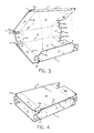
- Fig.3 is a schematic view showing the blank of Fig.l in a preliminary stage of the forming of a carton therefrom,
- Fig.4 is a schematic view showing a partially formed carton which has been formed from the blank of Fig.l,
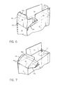
- Fig.5 is an enlarged fragmentary schematic view showing a portion of a carton as it is being formed from the blank of Fig.l,
- Fig.6 is a further enlarged fragmentary schematic view of a portion of a carton as it is being formed from the blank of Fig.l,
- Fig.7 is an enlarged fragmentary schematic view of the portion of the carton which is. depicted in Fig.6 at a subsequent stage of its formation,
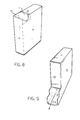
- Fig.8 is a schematic view of the assembled carton which has been formed from the blank of Fig.l,
- Fig.9 is a schematic view showing a pour-out spout feature of the carton which has been formed from the blank of Fig.l,
- Fig.lO is an enlarged fragmentary schematic view of a portion of a carton as it is being formed in an alternative manner from the blank of Fig.l, and
- Fig.11 is an enlarged fragmentary schematic view of the carton which is depicted in Fig.10 at a subsequent stage of its formation.
- As is shown in Fig.l, there is provided a die-cut blank, generally indicated by reference numeral 11, from which a parallelepiped or six-sided carton may be formed. In the case of a blank for a carton for the packaging of a breakfast cereal, blank 11 may be advantageously formed from expanded general purpose or impact polystyrene in a thickness of the order of 36-40 mils (0.036-0.040 in.) and of a density of the order of 6-8 pounds per cubic foot. Preferably blank 11 is also provided with thin layers of a non-expanded polymeric material such as polyethylene on the opposed surfaces thereof for improved resistance to moisture vapour transmission. These surface layers, for example 1.5 mils in thickness on the outside surface and 0.5 mils in thickness on the inside surface, can be formed on a core of expanded polystyrene by co-extrusion, extrusion coating or lamination in a known manner, and preferably involve the use of a suitable agent to effect bonding of these dissimilar materials, such as ethylene vinyl acetate, which can be utilized between the layers or in one or both of the adjoining layers. In any case, the blank comprises serially connected rectangularly-
shaped panels fold lines flap 19 which is integrally connected topanel 15 alongfold line 21, which may also be formed by scoring. - As is depicted in Figures 3 and 4, the forming of a carton from blank 11 involves folding the blank along
fold lines panel 12 into a position overlyingflap 19 to form the side seam of the carton.Panel 12 andflap 19 are joined to one another in this tubular configuration by heat sealing or by the use of an adhesive, or by other known means for forming a joint in a carton. - The portion of the carton which normally comprises the bottom of the carton when it is in an upright position is formed by a series of
flaps panels fold lines Flaps slots fold lines edge 22a offlap 22 is inwardly offset from the edge 12a of blank 11 to formslot 34 in conjunction with edge 19b ofextension 19a offlap 19 on assembly.Slot 31 helps to define, with anextension 16a offold line 16 and afold line 16b extending from the juncture offold lines gusset portion 35 in blank 11. This gusset is compressed to substantially less than its original thickness in the die-cutting operation which is utilized to form blank 11, for example to about the thickness of the scored fold lines or about no more than one half the original thickness of blank 11. Similar triangularly shapedcompressed gusset areas slots compressed gusset area 39 is formed in theextension 19a which extends beyondscore line 29, almost to the end offlap 25. - As is partially shown in Figure 5, the end structure for the carton to be formed from blank 11 is formed by folding end flaps 22 (and 24) to extend inwardly from panels 12 (and 14) and generally at right angles thereto. One of the remaining flaps, shown as
flap 25, is then inwardly folded to overlie flaps 22 (and 24), and the remaining flap, shown asflap 23, is then inwardly folded to overlieflap 25. The innermost offlaps flap 25, may be advantageously provided with triangularly-shaped notchedareas gusset areas gusset areas positions overlying flap 22, andgusset areas position overlying flap 24, to effectively seal the corners formed at the bottom of the carton. The superimposed flaps may then be joined to one another, as by heat-sealing, to permanently secure the bottom structure of the carton. - While the top structure of the carton formed from blank 11 may be identical to the heretofore described bottom structure, in a preferred embodiment it is provided at one end thereof with a reclosable pour-out spout in accordance with the invention covered in co-pending United States Patent Application Serial No. 638,145. Thus, the top corner away from the reclosable pour-out spout is formed by
flap 42 which is attached topanel 12 alongfold line 46 similar to the attachment offlap 22 alongfold line 26, and bypartial flaps 43 and 4-5 which are attached topanels fold lines flap 43 being separated fromflap 42 by partial depth slot 51 (which is similar to slot 31). The pour-out feature is provided by irregularly shapedflap 44 which is attached partially topanel 14 alongfold line 48 and partially topanels portions fold lines Flap 44 is comprised of a rectangularly-shapedcentral portion 44a and generally L-shaped portions central portion 44a and which are foldable relative tocentral portion 44a alongfold lines Fold lines fold lines Flap 44 also comprises an outwardly extendingmarginal tab portion 44d which is attached tocentral portion 44a alongfold line 44e. Additionally, the legs of L-shaped portions fold lines flap 44 are separated fromflaps narrow slots - In one assembly of the top structure of the carton, after the tubular structure of Figure 4 has been formed, L-
shaped portions lines shaped portions central portion 44a. As is shown in Figure 8, the-outwardly projecting folded L-shaped portions are then folded downwardly to overliecarton sides sensitive tape 61. - The package is shown in a partially inverted position in Figure 9 and in an opened position with the structure formed from
flap 44 constituting a pour-out spout, and the package can be reclosed, as is desirable when only a portion of the contents is withdrawn, by reclosing the pour-out spout into the configuration depicted in Figure 8, and the reclosed carton can be secured in such position without the need for reapplyingtape 61, or a replacement therefor, bybending tab portion 44d offlap 44 downwardly to insert it in the slot defined byslots - An alternative assembly of the top structure of the carton is shown in Figures 10 and 11, wherein the L-
shaped portions lines sides - The best mode known to carry out this invention has been described above in terms sufficiently full, clear, concise and exact as to enable any person skilled in the art to make and use the same. It is to be understood, however, that certain modifications of the above-described mode of practicing the invention can be made by a skilled artisan without departing from the scope of invention as defined by the appended claims.
Claims (9)
Priority Applications (1)
| Application Number | Priority Date | Filing Date | Title |
|---|---|---|---|
| AT85305533T ATE42525T1 (en) | 1984-08-06 | 1985-08-02 | POLYMERIC MATERIAL CONTAINER AND CUTTING FOR ITS MANUFACTURE. |
Applications Claiming Priority (2)
| Application Number | Priority Date | Filing Date | Title |
|---|---|---|---|
| US63814484A | 1984-08-06 | 1984-08-06 | |
| US638144 | 1984-08-06 |
Publications (3)
| Publication Number | Publication Date |
|---|---|
| EP0171275A2 true EP0171275A2 (en) | 1986-02-12 |
| EP0171275A3 EP0171275A3 (en) | 1987-03-25 |
| EP0171275B1 EP0171275B1 (en) | 1989-04-26 |
Family
ID=24558826
Family Applications (1)
| Application Number | Title | Priority Date | Filing Date |
|---|---|---|---|
| EP85305533A Expired EP0171275B1 (en) | 1984-08-06 | 1985-08-02 | Carton and blank therefor of polymeric material |
Country Status (4)
| Country | Link |
|---|---|
| EP (1) | EP0171275B1 (en) |
| AT (1) | ATE42525T1 (en) |
| AU (1) | AU558448B2 (en) |
| DE (1) | DE3569715D1 (en) |
Cited By (5)
| Publication number | Priority date | Publication date | Assignee | Title |
|---|---|---|---|---|
| WO1989005267A1 (en) * | 1987-12-11 | 1989-06-15 | Schouw Packing A/S | A packaging container, in particular for dry, tricklable products |
| EP0531581A1 (en) * | 1991-09-10 | 1993-03-17 | The Procter & Gamble Company | Flip top bag-in-box |
| EP0536103A1 (en) * | 1991-10-04 | 1993-04-07 | AB AKERLUND & RAUSING | Package made of cardboard or other foldable material |
| EP0881152A1 (en) * | 1997-05-28 | 1998-12-02 | SCA Packaging Limited | Carton with leak-proof corner construction and blank therefor |
| EP4169845A1 (en) * | 2021-10-21 | 2023-04-26 | Good !D bv | Packaging for pet food kibble |
Citations (4)
| Publication number | Priority date | Publication date | Assignee | Title |
|---|---|---|---|---|
| US1987647A (en) * | 1933-01-04 | 1935-01-15 | Charles P Wellman | Container |
| DE1704922A1 (en) * | 1967-07-19 | 1971-06-03 | Papierfabrik Gmbh | Process for producing collapsible containers such as boxes, boxes and other packaging units from a collapsible material |
| FR2253675A1 (en) * | 1973-12-06 | 1975-07-04 | Focke Pfuhl Verpack Automat | Cigarette packing from foldable material - with triangular section between long and short end flaps sealing packing corners |
| US3907193A (en) * | 1974-04-08 | 1975-09-23 | Autoplex Corp | Plastic folding containers and process and apparatus for making same |
-
1985
- 1985-08-02 AU AU45725/85A patent/AU558448B2/en not_active Ceased
- 1985-08-02 AT AT85305533T patent/ATE42525T1/en not_active IP Right Cessation
- 1985-08-02 DE DE8585305533T patent/DE3569715D1/en not_active Expired
- 1985-08-02 EP EP85305533A patent/EP0171275B1/en not_active Expired
Patent Citations (4)
| Publication number | Priority date | Publication date | Assignee | Title |
|---|---|---|---|---|
| US1987647A (en) * | 1933-01-04 | 1935-01-15 | Charles P Wellman | Container |
| DE1704922A1 (en) * | 1967-07-19 | 1971-06-03 | Papierfabrik Gmbh | Process for producing collapsible containers such as boxes, boxes and other packaging units from a collapsible material |
| FR2253675A1 (en) * | 1973-12-06 | 1975-07-04 | Focke Pfuhl Verpack Automat | Cigarette packing from foldable material - with triangular section between long and short end flaps sealing packing corners |
| US3907193A (en) * | 1974-04-08 | 1975-09-23 | Autoplex Corp | Plastic folding containers and process and apparatus for making same |
Cited By (7)
| Publication number | Priority date | Publication date | Assignee | Title |
|---|---|---|---|---|
| WO1989005267A1 (en) * | 1987-12-11 | 1989-06-15 | Schouw Packing A/S | A packaging container, in particular for dry, tricklable products |
| US5322211A (en) * | 1987-12-11 | 1994-06-21 | Schouw Packing A/S | Packaging carton for dry, flowable products |
| EP0531581A1 (en) * | 1991-09-10 | 1993-03-17 | The Procter & Gamble Company | Flip top bag-in-box |
| EP0536103A1 (en) * | 1991-10-04 | 1993-04-07 | AB AKERLUND & RAUSING | Package made of cardboard or other foldable material |
| EP0881152A1 (en) * | 1997-05-28 | 1998-12-02 | SCA Packaging Limited | Carton with leak-proof corner construction and blank therefor |
| EP4169845A1 (en) * | 2021-10-21 | 2023-04-26 | Good !D bv | Packaging for pet food kibble |
| BE1029867B1 (en) * | 2021-10-21 | 2023-05-23 | Good !D Bv | PACKAGING FOR PET FOOD KITCHES |
Also Published As
| Publication number | Publication date |
|---|---|
| AU558448B2 (en) | 1987-01-29 |
| EP0171275A3 (en) | 1987-03-25 |
| AU4572585A (en) | 1986-03-27 |
| EP0171275B1 (en) | 1989-04-26 |
| DE3569715D1 (en) | 1989-06-01 |
| ATE42525T1 (en) | 1989-05-15 |
Similar Documents
| Publication | Publication Date | Title |
|---|---|---|
| US4989780A (en) | Blank for sealed carton with integral reclosable pour-out spout | |
| US6216943B1 (en) | Fresh fold package | |
| US2983421A (en) | Compartmented carton | |
| RU2134652C1 (en) | Carton reinforced handle | |
| US3667666A (en) | Foldable storage box | |
| US2473055A (en) | Reclosing carton | |
| US2239398A (en) | Packaging | |
| US2473492A (en) | Reclosable carton | |
| US4319710A (en) | Reinforced end sealed container | |
| US3133688A (en) | Reclosable angle spout carton | |
| US4657177A (en) | Carton formed from blank of expanded polymer material and blank therefor | |
| US4121757A (en) | Flap arrangement for a carrier carton | |
| US5758971A (en) | Container made of flexible material with a handle system formed without external added material | |
| US4195765A (en) | Carton with integral handle | |
| US3459358A (en) | Prewrapped gift carton | |
| US3185374A (en) | Carton and blank therefor | |
| EP0171275A2 (en) | Carton and blank therefor of polymeric material | |
| US3735914A (en) | Sift-proof dispensing carton | |
| GB2321236A (en) | Cartons | |
| US3189249A (en) | Container and blank therefor | |
| US2516085A (en) | Container | |
| US3764058A (en) | Pour spout carton having a hinged reclosable lid | |
| US3058645A (en) | Carton for ice cream or the like | |
| US4802620A (en) | Gable top carton for preventing wicking | |
| US3616987A (en) | Carton with reclosable corner portion |
Legal Events
| Date | Code | Title | Description |
|---|---|---|---|
| PUAI | Public reference made under article 153(3) epc to a published international application that has entered the european phase |
Free format text: ORIGINAL CODE: 0009012 |
|
| AK | Designated contracting states |
Designated state(s): AT BE CH DE FR GB IT LI LU NL SE |
|
| PUAL | Search report despatched |
Free format text: ORIGINAL CODE: 0009013 |
|
| AK | Designated contracting states |
Kind code of ref document: A3 Designated state(s): AT BE CH DE FR GB IT LI LU NL SE |
|
| 17P | Request for examination filed |
Effective date: 19870918 |
|
| 17Q | First examination report despatched |
Effective date: 19871204 |
|
| RAP1 | Party data changed (applicant data changed or rights of an application transferred) |
Owner name: OWENS-ILLINOIS PLASTIC PRODUCTS INC. |
|
| GRAA | (expected) grant |
Free format text: ORIGINAL CODE: 0009210 |
|
| AK | Designated contracting states |
Kind code of ref document: B1 Designated state(s): AT BE CH DE FR GB IT LI LU NL SE |
|
| PG25 | Lapsed in a contracting state [announced via postgrant information from national office to epo] |
Ref country code: SE Effective date: 19890426 Ref country code: NL Effective date: 19890426 Ref country code: LI Effective date: 19890426 Ref country code: IT Free format text: LAPSE BECAUSE OF FAILURE TO SUBMIT A TRANSLATION OF THE DESCRIPTION OR TO PAY THE FEE WITHIN THE PRESCRIBED TIME-LIMIT;WARNING: LAPSES OF ITALIAN PATENTS WITH EFFECTIVE DATE BEFORE 2007 MAY HAVE OCCURRED AT ANY TIME BEFORE 2007. THE CORRECT EFFECTIVE DATE MAY BE DIFFERENT FROM THE ONE RECORDED. Effective date: 19890426 Ref country code: FR Free format text: THE PATENT HAS BEEN ANNULLED BY A DECISION OF A NATIONAL AUTHORITY Effective date: 19890426 Ref country code: CH Effective date: 19890426 Ref country code: BE Effective date: 19890426 Ref country code: AT Effective date: 19890426 |
|
| REF | Corresponds to: |
Ref document number: 42525 Country of ref document: AT Date of ref document: 19890515 Kind code of ref document: T |
|
| REF | Corresponds to: |
Ref document number: 3569715 Country of ref document: DE Date of ref document: 19890601 |
|
| REG | Reference to a national code |
Ref country code: CH Ref legal event code: PL |
|
| PG25 | Lapsed in a contracting state [announced via postgrant information from national office to epo] |
Ref country code: LU Free format text: LAPSE BECAUSE OF NON-PAYMENT OF DUE FEES Effective date: 19890831 |
|
| EN | Fr: translation not filed | ||
| NLV1 | Nl: lapsed or annulled due to failure to fulfill the requirements of art. 29p and 29m of the patents act | ||
| PLBE | No opposition filed within time limit |
Free format text: ORIGINAL CODE: 0009261 |
|
| STAA | Information on the status of an ep patent application or granted ep patent |
Free format text: STATUS: NO OPPOSITION FILED WITHIN TIME LIMIT |
|
| 26N | No opposition filed | ||
| PGFP | Annual fee paid to national office [announced via postgrant information from national office to epo] |
Ref country code: GB Payment date: 19920710 Year of fee payment: 8 |
|
| PGFP | Annual fee paid to national office [announced via postgrant information from national office to epo] |
Ref country code: DE Payment date: 19920828 Year of fee payment: 8 |
|
| PG25 | Lapsed in a contracting state [announced via postgrant information from national office to epo] |
Ref country code: GB Effective date: 19930802 |
|
| GBPC | Gb: european patent ceased through non-payment of renewal fee |
Effective date: 19930802 |
|
| PG25 | Lapsed in a contracting state [announced via postgrant information from national office to epo] |
Ref country code: DE Effective date: 19940503 |