EP0180904A2 - Cooling device - Google Patents
Cooling device Download PDFInfo
- Publication number
- EP0180904A2 EP0180904A2 EP85113773A EP85113773A EP0180904A2 EP 0180904 A2 EP0180904 A2 EP 0180904A2 EP 85113773 A EP85113773 A EP 85113773A EP 85113773 A EP85113773 A EP 85113773A EP 0180904 A2 EP0180904 A2 EP 0180904A2
- Authority
- EP
- European Patent Office
- Prior art keywords
- cooling device
- suction
- subcooler
- line
- refrigerant
- Prior art date
- Legal status (The legal status is an assumption and is not a legal conclusion. Google has not performed a legal analysis and makes no representation as to the accuracy of the status listed.)
- Granted
Links
Images

Classifications
-
- F—MECHANICAL ENGINEERING; LIGHTING; HEATING; WEAPONS; BLASTING
- F25—REFRIGERATION OR COOLING; COMBINED HEATING AND REFRIGERATION SYSTEMS; HEAT PUMP SYSTEMS; MANUFACTURE OR STORAGE OF ICE; LIQUEFACTION SOLIDIFICATION OF GASES
- F25B—REFRIGERATION MACHINES, PLANTS OR SYSTEMS; COMBINED HEATING AND REFRIGERATION SYSTEMS; HEAT PUMP SYSTEMS
- F25B7/00—Compression machines, plants or systems, with cascade operation, i.e. with two or more circuits, the heat from the condenser of one circuit being absorbed by the evaporator of the next circuit
-
- F—MECHANICAL ENGINEERING; LIGHTING; HEATING; WEAPONS; BLASTING
- F25—REFRIGERATION OR COOLING; COMBINED HEATING AND REFRIGERATION SYSTEMS; HEAT PUMP SYSTEMS; MANUFACTURE OR STORAGE OF ICE; LIQUEFACTION SOLIDIFICATION OF GASES
- F25B—REFRIGERATION MACHINES, PLANTS OR SYSTEMS; COMBINED HEATING AND REFRIGERATION SYSTEMS; HEAT PUMP SYSTEMS
- F25B1/00—Compression machines, plants or systems with non-reversible cycle
-
- F—MECHANICAL ENGINEERING; LIGHTING; HEATING; WEAPONS; BLASTING
- F25—REFRIGERATION OR COOLING; COMBINED HEATING AND REFRIGERATION SYSTEMS; HEAT PUMP SYSTEMS; MANUFACTURE OR STORAGE OF ICE; LIQUEFACTION SOLIDIFICATION OF GASES
- F25B—REFRIGERATION MACHINES, PLANTS OR SYSTEMS; COMBINED HEATING AND REFRIGERATION SYSTEMS; HEAT PUMP SYSTEMS
- F25B2400/00—General features or devices for refrigeration machines, plants or systems, combined heating and refrigeration systems or heat-pump systems, i.e. not limited to a particular subgroup of F25B
- F25B2400/07—Details of compressors or related parts
- F25B2400/074—Details of compressors or related parts with multiple cylinders
-
- F—MECHANICAL ENGINEERING; LIGHTING; HEATING; WEAPONS; BLASTING
- F25—REFRIGERATION OR COOLING; COMBINED HEATING AND REFRIGERATION SYSTEMS; HEAT PUMP SYSTEMS; MANUFACTURE OR STORAGE OF ICE; LIQUEFACTION SOLIDIFICATION OF GASES
- F25B—REFRIGERATION MACHINES, PLANTS OR SYSTEMS; COMBINED HEATING AND REFRIGERATION SYSTEMS; HEAT PUMP SYSTEMS
- F25B2400/00—General features or devices for refrigeration machines, plants or systems, combined heating and refrigeration systems or heat-pump systems, i.e. not limited to a particular subgroup of F25B
- F25B2400/13—Economisers
-
- F—MECHANICAL ENGINEERING; LIGHTING; HEATING; WEAPONS; BLASTING
- F25—REFRIGERATION OR COOLING; COMBINED HEATING AND REFRIGERATION SYSTEMS; HEAT PUMP SYSTEMS; MANUFACTURE OR STORAGE OF ICE; LIQUEFACTION SOLIDIFICATION OF GASES
- F25B—REFRIGERATION MACHINES, PLANTS OR SYSTEMS; COMBINED HEATING AND REFRIGERATION SYSTEMS; HEAT PUMP SYSTEMS
- F25B2400/00—General features or devices for refrigeration machines, plants or systems, combined heating and refrigeration systems or heat-pump systems, i.e. not limited to a particular subgroup of F25B
- F25B2400/23—Separators
-
- F—MECHANICAL ENGINEERING; LIGHTING; HEATING; WEAPONS; BLASTING
- F25—REFRIGERATION OR COOLING; COMBINED HEATING AND REFRIGERATION SYSTEMS; HEAT PUMP SYSTEMS; MANUFACTURE OR STORAGE OF ICE; LIQUEFACTION SOLIDIFICATION OF GASES
- F25B—REFRIGERATION MACHINES, PLANTS OR SYSTEMS; COMBINED HEATING AND REFRIGERATION SYSTEMS; HEAT PUMP SYSTEMS
- F25B2600/00—Control issues
- F25B2600/25—Control of valves
- F25B2600/2509—Economiser valves
Definitions
- the invention relates to a cooling device with a piston compressor having a plurality of cylinders, a condenser, an expansion element and an evaporator, with a line connecting the piston compressor, the condenser, the expansion element and the evaporator to one another for an evaporable refrigerant liquid, and with an in the line between the condenser and expansion element, provided with a vaporizable coolant subcooler for the refrigerant.
- the object is achieved in that part of the refrigerant is used as the coolant for the subcooler, and an outlet opening of the subcooler for evaporated coolant is connected via an additional suction line to the suction side of part of the cylinders of the piston compressor.
- a multi-cylinder, motor-driven compressor 1 sucks vapor Refrigerant via a so-called suction line 2 from an evaporator 3 at a relatively low pressure and compresses the steam to a relatively high pressure in order to convey it via a so-called compressed gas line 4 into a condenser 5.
- a heat transfer medium for example air, water or the like
- the liquefied (and slightly subcooled) refrigerant is passed via a liquid line 6 to an expansion device 7, the function of which is to feed an amount of refrigerant liquid adapted to the respective operating conditions into the evaporator 3.
- the expansion element 7 is also a throttling point between high and low pressure.
- the liquid refrigerant fed into the evaporator 3 and kept at low pressure evaporates by supplying heat and is then sucked off again by the compressor 1 via the suction line 2, either dry saturated or slightly overheated.
- cooling capacity the amount of heat absorbed in the evaporator 3
- the subcooler 8 has its own coolant circuit with compressor 11, suction line 12, pressure line 14,
- the circuit of the subcooler 8 also contains a solenoid valve 19.
- the refrigerant circuit connected to the compressor 1 is also referred to as the main circuit, the coolant circuit connected to the compressor 11 as a secondary circuit. Both circuits work physically in the same way.
- the delivery volume of the compressor 11 required for the secondary or subcooling circuit need only be approximately 10 to 25% of the delivery volume of the compressor 1 in order to achieve the desired liquid subcooling.
- the core of which is a compressor which combines the functions of the compressors 1 and 11.
- the common piston compressor 21 has six cylinders. Of these six cylinders, only a few (e.g. five cylinders) draw vaporous refrigerant via the suction line 22 from the evaporator 23 and, in the same way as previously described with reference to the main circuit of FIG. 1, convey via the compressed gas line 24 into the common condenser 25. After leaving the condenser 25, the liquefied refrigerant is passed directly through the subcooler 28 to the expansion element 27 via a first line A of the liquid line 26 and is fed by the latter into the evaporator 23 in a controlled manner and, after evaporation, is sucked off again by the piston compressor 21.
- a few e.g. five cylinders
- a partial flow of the liquefied refrigerant is fed into the subcooler 28 in a controlled manner via a further line B of the liquid line 26 via a remotely controlled solenoid valve 29 and through a further expansion element 30.
- the refrigerant evaporates due to this partial stream of the heat supply by the relatively warmer K älteschierikeit of the strand A and is then used as an additional suction vapor, with an outlet opening 31 of the subcooler 28 pumped connected suction line 32.
- This pumping takes place according to the invention via the cylinder or cylinders of the piston compressor 21-, the suction chambers of which are not connected to the line 22 but to the line 32. From the suction side of this or these cylinders, the suction steam is then conveyed to a common pressure chamber of the piston compressor 21 and mixed there with the steam of the main compressor part (originating from the suction line 22). This process causes the refrigerant liquid to be subcooled in the subcooler 8 with the aforementioned increase in performance resulting therefrom.
- FIG. 3 shows a modified arrangement in which the subcooler 38 is designed as an "open liquid collector", ie does not act as a heat exchanger like the subcooler 28 in the case of FIG. 2. Corresponding parts are provided with the same reference numerals in FIGS. 2 and 3.
- the principle of operation of the "open" subcooler 38 is based on the fact that part of the liquid refrigerant contained therein is sucked off in vapor form by the relevant part of the compressor 21 via the additional suction line 32.
- the K included in the sub-cooler 38 älteffentechnik is subcooled thereby.
- the solenoid valve 29 has the task of interrupting the refrigerant flow during the standstill periods and is opened with a certain delay after the start.
- a regulator 39 in the additional suction line 32 controls the pressure and the flowing amount of refrigerant.
- a pressure regulator 4o is provided in the system according to FIG. 3, which is required to maintain a certain condensing pressure.
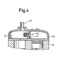
- FIG. 4 shows one of the twin cylinder heads.
- the other cylinder heads of the compressor are designed in the usual way.
- the suction chamber of the cylinder head shown in FIG. 4 is divided into two suction chambers 42 and 43 by a partition 41.
- the chamber 42 is connected to the subcooler via the additional suction line 32 in the manner described.
- the suction chamber 43 like the suction chambers of the other cylinders, is connected to the evaporator 23 via the suction line 22.
- One of the pistons 44 of the compressor is visible in FIG. 3. All cylinders of the arrangement are connected to a common pressure chamber (not shown) in the usual way.
- a valve device 45 is arranged in the partition 41, which is designed either (as shown) as a check valve 46 or as a solenoid valve can be.
- the compressor compressor 21
- the subcooler is first pumped down to a suction pressure that corresponds to that of the other cylinders.
- the check valve opens automatically, the cylinder in question then works in parallel with the other compressor part.
- valve device 41 as a solenoid valve, this must already be opened when the solenoid valve 29 closes.
- the cooling device described offers the following advantages: at the start, the system can initially stabilize by delayed opening of the solenoid valve 29. The risk of refrigerant transfer from the subcooler to the compressor during the Start-up phase is avoided by the aforementioned empty pumping. By switching the supercooling circuit on and off, power control is possible without affecting the application limits. By combining the main circuit with its secondary circuit, there is no need for second compressors and condensers with accessories. This also results in a simplified line assembly. A subsequent retrofitting of the compressor to the embodiment according to FIG. 4 is possible.
Abstract
Description
Die Erfindung betrifft eine Kühlvorrichtung mit einem mehrere Zylinder aufweisenden Kolbenverdichter, einem Verflüssiger, einem Expansionsorgan und einem Ver- da.mpfer, mit einer den Kolbenverdichter, den Verflüssiger, das Expansionsorgan und den Verdampfer miteinander verbindenden Leitung für eine verdampfbare Kälteflüssigkeit, und mit einem in der Leitung zwischen Verflüssiger und Expansionsorgan vorgesehenem, mit einem verdampfbaren Kühlmittel arbeitenden Unterkühler für die Kälteflüssigkeit.The invention relates to a cooling device with a piston compressor having a plurality of cylinders, a condenser, an expansion element and an evaporator, with a line connecting the piston compressor, the condenser, the expansion element and the evaporator to one another for an evaporable refrigerant liquid, and with an in the line between the condenser and expansion element, provided with a vaporizable coolant subcooler for the refrigerant.
Bei bekannten Kühlvorrichtungen oder Kälteanlagen dieser Art werden Leistung und Wirkungsgrad manchmal durch einen zusätzlichen Unterkühlungskreislauf gesteigert, insbesondere bei Systemen mit relativ großer Differenz zwischen kalter und warmer Seite.In known cooling devices or refrigeration systems of this type, performance and efficiency are sometimes increased by an additional supercooling circuit, in particular in systems with a relatively large difference between the cold and the warm side.
Hierzu wird neben dem Hauptkreislauf der Kälteflüssigkeit ein Nebenkreislauf für das Kühlmittel des Unterkühlers mit eigenem Verdichter, Verflüssiger und Expansionsorgan benötigt, wobei der Unterkühler dann als Verdampfer wirkt.For this purpose, a secondary circuit for the coolant of the subcooler with its own compressor, condenser and Expansion device needed, the subcooler then acts as an evaporator.
Diese Kühlvorrichtungen mit Unterkühlung der Kälteflüssigkeit haben sich wegen des erforderlichen hohen Aufwandes bisher noch nicht durchgesetzt. Abgesehen von dem hohen Aufwand ist der Verdichter des den Unterkühler enthaltenden Nebenkreislaufes auch einer erhöhten Gefahr von Kälteflüssigkeitsverlagerung ins Schmieröl während der Stillstandsphasen ausgesetzt. Der Grund dafür liegt darin, daß der Nebenkreislauf etwas zeitverzögert .zum Hauptkreislauf in Betrieb gesetzt wird. Bei der Inbetriebnahme des Hauptkreislaufes erwärmen sich dessen Kälteflüssigkeitsleitung und der Unterkühler, wodurch eine Kühlmittelverlagerung in Saugleitung und Verdichter des Nebenkreislaufes hervorgerufen werden. Als Folge hiervon können mangelhafte Schmierung sowie öl- und Flüssigkeitsschläge beim Start auftreten.These cooling devices with subcooling of the cooling liquid have not yet become established because of the high outlay required. Apart from the high cost of the compressor is exposed to the subcooler containing by-cycle also an increased danger of refrigerant liquid shift to the lubricating oil during lactation Stan d sphasen. The reason for this is that the secondary circuit is started with a slight delay to the main circuit. When the main circuit is started up, its refrigerant line and the subcooler heat up, causing a coolant shift in the suction line and compressor of the secondary circuit. As a result, poor lubrication as well as oil and liquid slugs can occur at the start.
Es ist daher Aufgabe der Erfindung, eine gattungsgemäße Kühlvorrichtung mit Unterkühlung der Kälteflüssigkeit derart zu verbessern, daß unter Beibehaltung ihrer Vorteile der zu treffende Aufwand gegenüber bekannten Vorrichtungen erheblich reduziert ist und Betriebsstörungen der genannten Art (mangelhafte Schmierung sowie öl- und Flüssigkeitsschläge beim Start) ausgeschaltet sind.It is therefore an object of the invention to improve a generic cooling device with subcooling of the refrigerant in such a way that, while maintaining its advantages, the effort to be taken is considerably reduced compared to known devices and operational malfunctions of the type mentioned (inadequate lubrication and oil and liquid strikes at start) are eliminated are.
Die Aufgabe wird erfindungsgemäß dadurch gelöst, daß als Kühlmittel für den Unterkühler ein Teil der Kälteflüssigkeit verwendet ist, und eine Auslaßöffnung des Unterkühlers für verdampftes Kühlmittel über eine zusätzliche Saugleitung mit der Saugseite eines Teiles der Zylinder des Kolbenverdichters verbunden ist.The object is achieved in that part of the refrigerant is used as the coolant for the subcooler, and an outlet opening of the subcooler for evaporated coolant is connected via an additional suction line to the suction side of part of the cylinders of the piston compressor.
Die nachstehende Beschreibung bevorzugter Ausführungsformen der Erfindung dient im Zusammenhang mit beiliegender Zeichnung der weiteren Erläuterung. Es zeigen:
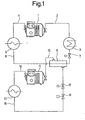
- Fig. 1 eine herkömmliche Kühlvorrichtung mit Unterkühlung der Kälteflüssigkeit;
- Fig. 2 eine erste Ausführungsform einer Kühlvorrichtung mit verbesserter Unterkühlung der Kälteflüssigkeit;
- Fig. 3 eine zweite Ausführungsform einer Kühlvorrichtung mit verbesserter Unterkühlung der Kälteflüssigkeit und
- Fig. 4 eine Ventilanordnung an der Saugseite zweier Zylinder eines Kolbenverdichters.
- 1 shows a conventional cooling device with subcooling of the refrigerant.
- 2 shows a first embodiment of a cooling device with improved subcooling of the refrigerant liquid;
- Fig. 3 shows a second embodiment of a cooling device with improved sub-cooling of the refrigerant and
- Fig. 4, a valve assembly on the suction side of two cylinders of a K olbenverdichters.
Bei der in Fig. 1 dargestellten herkömmlichen Kühlvorrichtung saugt ein mehrere Zylinder aufweisender, motorisch angetriebener Verdichter 1 dampfförmiges Kältemittel über eine sogenannte Saugleitung 2 aus einem Verdampfer 3 bei relativ niedrigem Druck ab und komprimiert den Dampf auf einen realtiv hohen Druck, um ihn über eine sogenannte Druckgasleitung 4 in einen Verflüssiger 5 zu fördern. Im Verflüssiger 5 wird über ein Wärmeträgermedium (z. B. Luft, Wasser od. dgl.) Wärme abgeführt, so daß der unter hohem Druck stehende Dampf kondensiert. über eine Flüssigkeitsleitung 6 wird das verflüssigte (und geringfügig unterkühlte) Kältemittel zu einem Expansionsorgan 7 geleitet, dessen Aufgabe darin besteht, eine den jeweiligen Betriebsbedingungen angepaßte Menge an Kältemittelflüssigkeit in den Verdampfer 3 einzuspeisen. Das Expansionsorgan 7 ist zugleich Drosselstelle zwischen Hoch- und Niederdruck. Das in den Verdampfer 3 eingespeiste, auf niedrigem Druck gehaltene, flüssige Kältemittel verdampft durch Wärmezufuhr und wird anschließend wieder über die Saugleitung 2 - entweder trocken gesättigt oder geringfügig überhitzt - vom Verdichter 1 abgesaugt.In the conventional cooling device shown in FIG. 1, a multi-cylinder, motor-driven compressor 1 sucks vapor Refrigerant via a so-called
Es läßt sich zeigen, daß die im Verdampfer 3 aufgenommene Wärmemenge ("Kälteleistung") um so größer ist, je tiefer die Temperatur des Kältemittels vor dem Expansionsorgan 7 liegt. Daher ist es bekannt, in der Flüssigkeitsleitung 6 einen sogenannten Unterkühler 8 vorzusehen, der das flüssige Kältemittel abkühlt. Dem Unterkühler 8 ist ein eigener Kühlmittelkreislauf mit Verdichter 11, Saugleitung 12, Druckleitung 14,It can be shown that the amount of heat absorbed in the evaporator 3 (“cooling capacity”) is greater the lower the temperature of the refrigerant in front of the
Verflüssiger 15, Flüssigkeitsleitung 16 und Expansionsorgan 17 zugeordnet, wobei der Unterkühler 8 als "Verdampfer" wirkt und das Kältemittel in der Leitung 6 kühlt. Der Kreislauf des Unterkühlers 8 enthält weiterhin ein Magnetventil 19. Der an den Verdichter 1 angeschlossene Kältemittelkreislauf wird auch als Hauptkreislauf, der an den Verdichter 11 angeschlossene Kühlmittelkreislauf als Nebenkreislauf bezeichnet. Beide Kreisläufe wirken physikalisch in der gleichen Weise.
Da der Verdampfungsvorgang im Unterkühler 8 aufgrund der relativ hohen Flüssigkeitstemperatur des Hauptkreislaufes bei einem deutlich höheren Temperaturniveau erfolgen kann als der Verdampfungsvorgang im Verdampfer 3, liegen sowohl der relative Massenstrom wie auch der Wirkungsgrad des Nebenkreislaufes höher als im Hauptkreislauf. Daraus resultiert, daß das für den Neben- oder Unterkühlungskreislauf erforderliche Fördervolumen des Verdichters 11 lediglich etwa 10 bis 25 % des Fördervolumens des Verdichters 1 betragen muß, um die gewünschte Flüssigkeitsunterkühlung zu erzielen. Dies ist Ansatzpunkt der Erfindung, deren Kernstück ein Verdichter ist, der die Funktionen der Verdichter 1 und 11 in sich vereinigt. Nachdem ein solcher einziger Verdichter, wie noch beschrieben werden wird, nur in seinem Zylinderbereich, und zwar saugseitig, unterteilt ist, jedoch einen gemeinsamen Antrieb (Kurbeltrieb) und eine gemeinsame Druckkammer besitzt, kann ohne Nachteile auf die Betriebssicherheit auch ein gemeinsamer, einziger Verflüssiger statt der Verflüssiger 5 und 15 verwendet werden.Since the evaporation process in the
Die Erfindung wird nachstehend anhand zweier Ausführungsbeispiele gemäß Fig. 2 und 3 weiter erläutert.The invention is further explained below using two exemplary embodiments according to FIGS. 2 and 3.
In Fig. 2 hat der gemeinsame Kolbenverdichter 21 sechs Zylinder. Von diesen sechs Zylindern saugen lediglich einige (z. B. fünf Zylinder) dampfförmiges Kältemittel über die Saugleitung 22 aus dem Verdampfer 23 und fördern in gleicher Weise, wie zuvor anhand des Hauptkreislaufes der Fig. 1 beschrieben, über die Druckgasleitung 24 in den gemeinsamen Verflüssiger 25. Das verflüssigte Kältemittel wird nach dem Austritt aus dem Verflüssiger 25 über einen ersten Strang A der Flüssigkeitsleitung 26 direkt durch den Unterkühler 28 zum Expansionsorgan 27 geführt und von diesem geregelt in den Verdampfer 23 eingespeist sowie nach der Verdampfung vom Kolbenverdichter 21 wieder abgesaugt. Ein Teilstrom des verflüssigten Kältemittels wird über einen weiteren Strang B der Flüssigkeitsleitung 26 über ein ferngesteuertes Magnetventil 29 und durch ein weiteres Expansionsorgan 3o geregelt in den Unterkühler 28 eingespeist. Das Kältemittel dieses Teilstroms verdampft aufgrund der Wärmezufuhr durch die relativ wärmere Kältemittelflüssigkeit des Stranges A und wird dann als Saugdampf über eine zusätzliche, mit einer Auslaßöffnung 31 des Unterkühlers 28 verbundenen Saugleitung 32 abgepumpt.In Fig. 2 the
Dieses Abpumpen erfolgt erfindungsgemäß über den oder die Zylinder des Kolbenverdichters 21-, deren Saugkammern nicht mit der Leitung 22, sondern an die Leitung 32 angeschlossen sind. Von der Saugseite dieses oder dieser Zylinder wird der Saugdampf dann zu einer gemeinsamen Druckkammer des Kolbenverdichters 21 gefördert und dort mit dem Dampf des Hauptverdichterteils (aus der Saugleitung 22 stammend) vermischt. Dieser Vorgang bewirkt eine Unterkühlung der Kältemittelflüssigkeit im Unterkühler 8 mit der bereits erwähnten, hieraus resultierenden Leistungserhöhung.This pumping takes place according to the invention via the cylinder or cylinders of the piston compressor 21-, the suction chambers of which are not connected to the
Die Fig. 3 zeigt eine abgewandelte Anordnung, bei welcher der Unterkühler 38 als "offener Flüssigkeitssammler" ausgebildet ist, also nicht als Wärmetauscher wie der Unterkühler 28 im Falle der Fig. 2 wirkt. Einander entsprechende Teile sind in Fig. 2 und 3 mit den gleichen Bezugszeichen versehen.FIG. 3 shows a modified arrangement in which the
Das Wirkungsprinzip des "offenen" Unterkühlers 38 beruht darauf, daß ein Teil des darin befindlichen flüssigen Kältemittels vom betreffenden Teil des Verdichters 21 über die zusätzliche Saugleitung 32 dampfförmig abgesaugt wird. Die im Unterkühler 38 enthaltene Kältemittelflüssigkeit wird dadurch unterkühlt.The principle of operation of the "open"
Das Magnetventil 29 hat die Aufgabe, den Kältemittelfluß während der Stillstandsperioden zu unterbrechen und wird mit einer gewissen Verzögerung nach dem Start geöffnet. Ein Regler 39 in der zusätzlichen Saugleitung 32 kontrolliert den Druck und die strömende Kältemittelmenge. Zusätzlich ist im System gemäß Fig. 3 ein Druckregler 4o vorgesehen, der zur Aufrechterhaltung eines bestimmten Verflüssigungsdruckes benötigt wird.The
Die Fig. 4 zeigt einen der Twin-Zylinderköpfe eines . Vier-, Sechs- oder Acht-Zylinderkompressors in V-, W- oder WW-Ausführung. Die anderen Zylinderköpfe des Kompressors sind in üblicher Weise ausgeführt. Die Saugkammer des in Fig. 4 dargestellten Zylinderkopfes ist durch eine Trennwand 41 in zwei Saugkammern 42 und 43 unterteilt. Die Kammer 42 steht über die zusätzliche Saugleitung 32 in der beschriebenen Weise mit dem Unterkühler in Verbindung. Die Saugkammer 43 ist ebenso wie die Saugkammern der übrigen Zylinder über die Saugleitung 22 an den Verdampfer 23 angeschlossen. Einer der Kolben 44 des Kompressors ist in Fig. 3 sichtbar. Sämtliche Zylinder der Anordnung stehen mit einer gemeinsamen Druckkammer (nicht dargestellt) in der üblichen Weise in Verbindung.4 shows one of the twin cylinder heads. Four, six or eight cylinder compressors in V, W or WW design. The other cylinder heads of the compressor are designed in the usual way. The suction chamber of the cylinder head shown in FIG. 4 is divided into two
In der Trennwand 41 ist eine Ventileinrichtung 45 angeordnet, die entweder (wie dargestellt) als Rückschlagventil 46 oder auch als Magnetventil ausgeführt sein kann. Durch diese Ventileinrichtung ist der Kompressor (Verdichter 21) in der Lage, mit seinen sämtlichen Zylindern auch direkt auf den Verdampfer 23 zu arbeiten, solange das Ventil 29 geschlossen bleibt. In diesem Fall wird der Unterkühler zunächst bis zu einem Saugdruck leergepumpt, der demjenigen der anderen Zylinder entspricht. Das Rückschlagventil öffnet automatisch, der betreffende Zylinder arbeitet dann parallel zum anderen Verdichterteil.A
Wenn andererseits nach einer gewissen Stabilisierungsphase das Magnetventil 29 geöffnet wird, verdampft ein Teil des flüssigen Kältemittels im Unterkühler. Der Unterkühlungskreislauf arbeitet bei höherem Saugdruck (höhere Kälteleistung und Leistungszahl), so daß das Rückschlagventil im Zylinderkopf automatisch geschlossen bleibt. Der betreffende Zylinder hat dann keine Verbindung mehr zum Nachbarzylinder und bedient nur noch den Unterkühlungskreislauf.On the other hand, if the
Bei alternativer Ausbildung der Ventileinrichtung 41 als Magnetventil muß dieses beim Schließen des Magnetventils 29 bereits geöffnet werden.In an alternative embodiment of the valve device 41 as a solenoid valve, this must already be opened when the
Die beschriebene Kühlvorrichtung bietet folgende Vorteile: beim Start kann sich das System durch verzögertes öffnen des Magnetventils 29 zunächst einmal stabilisieren. Die Gefahr einer Kältemittelverlagerung aus dem Unterkühler in den Verdichter während der Anlaufphase wird durch das vorerwähnte Leerpumpen vermieden. Durch Zu- und Abschalten des Unterkühlungskreislaufes ist eine Leistungsregelung ohne Beeinträchtigung der Anwendungsgrenzen möglich. Durch die Kombination des Haupt- mit seinem Nebenkreislauf können zweite Verdichter und Verflüssiger mit Zubehör entfallen. Es ergibt sich somit auch eine vereinfachte Leitungsmontage. Ein nachträgliches Umrüsten des Verdichters auf die Ausführungsform gemäß Fig. 4 ist möglich.The cooling device described offers the following advantages: at the start, the system can initially stabilize by delayed opening of the
Claims (10)
Priority Applications (1)
| Application Number | Priority Date | Filing Date | Title |
|---|---|---|---|
| AT85113773T ATE46026T1 (en) | 1984-11-03 | 1985-10-29 | COOLING DEVICE. |
Applications Claiming Priority (2)
| Application Number | Priority Date | Filing Date | Title |
|---|---|---|---|
| DE3440253 | 1984-11-03 | ||
| DE19843440253 DE3440253A1 (en) | 1984-11-03 | 1984-11-03 | COOLING DEVICE |
Publications (3)
| Publication Number | Publication Date |
|---|---|
| EP0180904A2 true EP0180904A2 (en) | 1986-05-14 |
| EP0180904A3 EP0180904A3 (en) | 1986-10-08 |
| EP0180904B1 EP0180904B1 (en) | 1989-08-30 |
Family
ID=6249455
Family Applications (1)
| Application Number | Title | Priority Date | Filing Date |
|---|---|---|---|
| EP85113773A Expired EP0180904B1 (en) | 1984-11-03 | 1985-10-29 | Cooling device |
Country Status (3)
| Country | Link |
|---|---|
| EP (1) | EP0180904B1 (en) |
| AT (1) | ATE46026T1 (en) |
| DE (2) | DE3440253A1 (en) |
Cited By (9)
| Publication number | Priority date | Publication date | Assignee | Title |
|---|---|---|---|---|
| ES2092424A1 (en) * | 1992-09-16 | 1996-11-16 | Ornaque Carlos Gutierrez | Mixed-unit safety cooling system |
| EP0898128A2 (en) * | 1997-08-22 | 1999-02-24 | Carrier Corporation | Variariable refrigerant, intrastage compression heat pump |
| EP0837291A3 (en) * | 1996-08-22 | 2000-10-04 | Denso Corporation | Vapor compression type refrigerating system |
| EP1139039A1 (en) * | 2000-03-27 | 2001-10-04 | Carrier Corporation | Economizer circuit enhancement |
| EP1498667A2 (en) * | 2003-07-18 | 2005-01-19 | Star Refrigeration Ltd. | Improved transcritical refrigeration cycle |
| WO2005008148A1 (en) * | 2003-07-14 | 2005-01-27 | Carrier Corporation | Refrigerant compression system with selective subcooling |
| WO2006015741A1 (en) * | 2004-08-09 | 2006-02-16 | Linde Kältetechnik Gmbh | Refrigeration circuit and method for operating a refrigeration circuit |
| DE102005009173A1 (en) * | 2005-02-17 | 2006-08-24 | Bitzer Kühlmaschinenbau Gmbh | refrigeration plant |
| US8113008B2 (en) | 2004-08-09 | 2012-02-14 | Carrier Corporation | Refrigeration circuit and method for operating a refrigeration circuit |
Families Citing this family (4)
| Publication number | Priority date | Publication date | Assignee | Title |
|---|---|---|---|---|
| US4702086A (en) * | 1986-06-11 | 1987-10-27 | Turbo Coils Inc. | Refrigeration system with hot gas pre-cooler |
| US5095712A (en) * | 1991-05-03 | 1992-03-17 | Carrier Corporation | Economizer control with variable capacity |
| DE19826291A1 (en) * | 1998-06-12 | 1999-12-16 | Linde Ag | Process for operating a pump to convey boiling refrigerants or refrigerants |
| US10253766B2 (en) | 2015-05-13 | 2019-04-09 | Carrier Corporation | Economized reciprocating compressor |
Citations (8)
| Publication number | Priority date | Publication date | Assignee | Title |
|---|---|---|---|---|
| CH101888A (en) * | 1922-06-26 | 1923-10-16 | Sulzer Ag | Compression refrigeration machine. |
| US2320097A (en) * | 1941-08-20 | 1943-05-25 | Servel Inc | Refrigeration |
| FR2287666A1 (en) * | 1974-10-11 | 1976-05-07 | Primore Sales Inc | AUTOMATIC VALVE EQUIPPED WITH A REFRIGERANT COMPRESSOR |
| FR2304041A1 (en) * | 1975-03-11 | 1976-10-08 | Kvaerner Brug Kjoleavdelning | Gas liquefaction machine for refrigeration plant - has compact intercooler which encloses liquefied gas separator for shortening pipework |
| US4197719A (en) * | 1976-01-29 | 1980-04-15 | Dunham-Bush, Inc. | Tri-level multi-cylinder reciprocating compressor heat pump system |
| US4230470A (en) * | 1977-01-21 | 1980-10-28 | Hitachi, Ltd. | Air conditioning system |
| FR2503841A1 (en) * | 1981-04-09 | 1982-10-15 | Guillemin Georges | Heat extraction pump for heating buildings - has reservoir to compressor connection allowing lower exit temperatures from condenser |
| DE3301304A1 (en) * | 1982-02-26 | 1983-09-15 | Hitachi, Ltd., Tokyo | COOLING SYSTEM WITH A COMPRESSOR IN SPIRAL DESIGN |
-
1984
- 1984-11-03 DE DE19843440253 patent/DE3440253A1/en not_active Withdrawn
-
1985
- 1985-10-29 EP EP85113773A patent/EP0180904B1/en not_active Expired
- 1985-10-29 DE DE8585113773T patent/DE3572721D1/en not_active Expired
- 1985-10-29 AT AT85113773T patent/ATE46026T1/en not_active IP Right Cessation
Patent Citations (8)
| Publication number | Priority date | Publication date | Assignee | Title |
|---|---|---|---|---|
| CH101888A (en) * | 1922-06-26 | 1923-10-16 | Sulzer Ag | Compression refrigeration machine. |
| US2320097A (en) * | 1941-08-20 | 1943-05-25 | Servel Inc | Refrigeration |
| FR2287666A1 (en) * | 1974-10-11 | 1976-05-07 | Primore Sales Inc | AUTOMATIC VALVE EQUIPPED WITH A REFRIGERANT COMPRESSOR |
| FR2304041A1 (en) * | 1975-03-11 | 1976-10-08 | Kvaerner Brug Kjoleavdelning | Gas liquefaction machine for refrigeration plant - has compact intercooler which encloses liquefied gas separator for shortening pipework |
| US4197719A (en) * | 1976-01-29 | 1980-04-15 | Dunham-Bush, Inc. | Tri-level multi-cylinder reciprocating compressor heat pump system |
| US4230470A (en) * | 1977-01-21 | 1980-10-28 | Hitachi, Ltd. | Air conditioning system |
| FR2503841A1 (en) * | 1981-04-09 | 1982-10-15 | Guillemin Georges | Heat extraction pump for heating buildings - has reservoir to compressor connection allowing lower exit temperatures from condenser |
| DE3301304A1 (en) * | 1982-02-26 | 1983-09-15 | Hitachi, Ltd., Tokyo | COOLING SYSTEM WITH A COMPRESSOR IN SPIRAL DESIGN |
Cited By (17)
| Publication number | Priority date | Publication date | Assignee | Title |
|---|---|---|---|---|
| ES2092424A1 (en) * | 1992-09-16 | 1996-11-16 | Ornaque Carlos Gutierrez | Mixed-unit safety cooling system |
| EP0837291A3 (en) * | 1996-08-22 | 2000-10-04 | Denso Corporation | Vapor compression type refrigerating system |
| EP0898128A2 (en) * | 1997-08-22 | 1999-02-24 | Carrier Corporation | Variariable refrigerant, intrastage compression heat pump |
| EP0898128A3 (en) * | 1997-08-22 | 2001-09-05 | Carrier Corporation | Variariable refrigerant, intrastage compression heat pump |
| EP1139039A1 (en) * | 2000-03-27 | 2001-10-04 | Carrier Corporation | Economizer circuit enhancement |
| WO2005008148A1 (en) * | 2003-07-14 | 2005-01-27 | Carrier Corporation | Refrigerant compression system with selective subcooling |
| EP1498667A3 (en) * | 2003-07-18 | 2006-05-17 | Star Refrigeration Ltd. | Improved transcritical refrigeration cycle |
| EP1498667A2 (en) * | 2003-07-18 | 2005-01-19 | Star Refrigeration Ltd. | Improved transcritical refrigeration cycle |
| US7845190B2 (en) | 2003-07-18 | 2010-12-07 | Star Refrigeration Limited | Transcritical refrigeration cycle |
| WO2006015741A1 (en) * | 2004-08-09 | 2006-02-16 | Linde Kältetechnik Gmbh | Refrigeration circuit and method for operating a refrigeration circuit |
| US8113008B2 (en) | 2004-08-09 | 2012-02-14 | Carrier Corporation | Refrigeration circuit and method for operating a refrigeration circuit |
| US8844303B2 (en) | 2004-08-09 | 2014-09-30 | Carrier Corporation | Refrigeration circuit and method for operating a refrigeration circuit |
| US9476614B2 (en) | 2004-08-09 | 2016-10-25 | Carrier Corporation | Refrigeration circuit and method for operating a refrigeration circuit |
| US9494345B2 (en) | 2004-08-09 | 2016-11-15 | Carrier Corporation | Refrigeration circuit and method for operating a refrigeration circuit |
| DE102005009173A1 (en) * | 2005-02-17 | 2006-08-24 | Bitzer Kühlmaschinenbau Gmbh | refrigeration plant |
| WO2006087075A1 (en) * | 2005-02-17 | 2006-08-24 | Bitzer Kühlmaschinenbau Gmbh | Refrigeration plant |
| US7451617B2 (en) | 2005-02-17 | 2008-11-18 | Bitzer Kuhlmaschinenbau Gmbh | Refrigeration system |
Also Published As
| Publication number | Publication date |
|---|---|
| ATE46026T1 (en) | 1989-09-15 |
| DE3440253A1 (en) | 1986-05-15 |
| EP0180904B1 (en) | 1989-08-30 |
| DE3572721D1 (en) | 1989-10-05 |
| EP0180904A3 (en) | 1986-10-08 |
Similar Documents
| Publication | Publication Date | Title |
|---|---|---|
| DE2508417C2 (en) | Refrigeration system | |
| EP1789732B1 (en) | Refrigeration circuit and method for operating a refrigeration circuit | |
| DE60011196T2 (en) | Combined heat exchanger with evaporator, accumulator and suction line | |
| DE3046549C2 (en) | Device for liquefying natural gas or synthesis gas with low boiling point | |
| DE60113363T2 (en) | Refrigeration system with phase separation | |
| EP0180904A2 (en) | Cooling device | |
| DE2157079A1 (en) | Two-stage refrigeration system | |
| DE112004002189T5 (en) | Cooling system with evaporator and compressor | |
| WO2006015741A1 (en) | Refrigeration circuit and method for operating a refrigeration circuit | |
| DE3521060A1 (en) | Method for cooling and liquefying gases | |
| DE2709343A1 (en) | COUNTERFLOW AIR CONDITIONING | |
| EP0190319B1 (en) | Refrigerator or heat pump and jet pump therefor | |
| EP0021205B1 (en) | Hybrid compression-absorption method for operating heat pumps or refrigeration machines | |
| DE4122889C1 (en) | ||
| DE2261091A1 (en) | ARRANGEMENT FOR OIL COOLING IN REFRIGERATING COMPRESSORS OF THE ROTATION TYPE | |
| EP2215412A1 (en) | System for refrigeration, heating or air-conditioning technology, particularly refrigeration systems | |
| DE3431452A1 (en) | Cooling or freezing apparatus used as a heat pump | |
| DE2438418A1 (en) | Rotating vane gas compressor for refrigerating plant - has means for injecting the gas in liquid state into the compression chamber | |
| DE2837695A1 (en) | METHOD AND DEVICE FOR IMPROVING EFFICIENCY IN A REFRIGERATION SYSTEM | |
| DE2825076A1 (en) | HEAT PUMP SYSTEM | |
| DE19832682A1 (en) | Defrosting unit for evaporator of heat pump of air conditioner has line connecting one expansion valve to second expansion valve | |
| DE2200553A1 (en) | Relaxation and evaporation device for cooling machines | |
| CH665708A5 (en) | METHOD FOR OPERATING A REFRIGERANT CIRCUIT AND REFRIGERANT CIRCUIT FOR CARRYING OUT THE METHOD. | |
| DE2822965A1 (en) | METHOD AND DEVICE FOR COMPRESSION HEATING OR COOLING | |
| DE2839529A1 (en) | CLOSED CIRCULAR PROCESS FOR HEAT TRANSFER AND SYSTEM FOR ITS EXECUTION |
Legal Events
| Date | Code | Title | Description |
|---|---|---|---|
| PUAI | Public reference made under article 153(3) epc to a published international application that has entered the european phase |
Free format text: ORIGINAL CODE: 0009012 |
|
| AK | Designated contracting states |
Kind code of ref document: A2 Designated state(s): AT BE DE FR GB IT NL SE |
|
| PUAL | Search report despatched |
Free format text: ORIGINAL CODE: 0009013 |
|
| AK | Designated contracting states |
Kind code of ref document: A3 Designated state(s): AT BE DE FR GB IT NL SE |
|
| 17P | Request for examination filed |
Effective date: 19870404 |
|
| 17Q | First examination report despatched |
Effective date: 19880108 |
|
| GRAA | (expected) grant |
Free format text: ORIGINAL CODE: 0009210 |
|
| AK | Designated contracting states |
Kind code of ref document: B1 Designated state(s): AT BE DE FR GB IT NL SE |
|
| PG25 | Lapsed in a contracting state [announced via postgrant information from national office to epo] |
Ref country code: SE Effective date: 19890830 Ref country code: NL Effective date: 19890830 Ref country code: BE Effective date: 19890830 |
|
| REF | Corresponds to: |
Ref document number: 46026 Country of ref document: AT Date of ref document: 19890915 Kind code of ref document: T |
|
| ITF | It: translation for a ep patent filed |
Owner name: BARZANO' E ZANARDO MILANO S.P.A. |
|
| GBT | Gb: translation of ep patent filed (gb section 77(6)(a)/1977) | ||
| REF | Corresponds to: |
Ref document number: 3572721 Country of ref document: DE Date of ref document: 19891005 |
|
| PG25 | Lapsed in a contracting state [announced via postgrant information from national office to epo] |
Ref country code: AT Effective date: 19891029 |
|
| ET | Fr: translation filed | ||
| NLV1 | Nl: lapsed or annulled due to failure to fulfill the requirements of art. 29p and 29m of the patents act | ||
| PLBE | No opposition filed within time limit |
Free format text: ORIGINAL CODE: 0009261 |
|
| STAA | Information on the status of an ep patent application or granted ep patent |
Free format text: STATUS: NO OPPOSITION FILED WITHIN TIME LIMIT |
|
| 26N | No opposition filed | ||
| ITTA | It: last paid annual fee | ||
| PGFP | Annual fee paid to national office [announced via postgrant information from national office to epo] |
Ref country code: GB Payment date: 19941028 Year of fee payment: 10 Ref country code: FR Payment date: 19941028 Year of fee payment: 10 |
|
| PGFP | Annual fee paid to national office [announced via postgrant information from national office to epo] |
Ref country code: DE Payment date: 19941121 Year of fee payment: 10 |
|
| PG25 | Lapsed in a contracting state [announced via postgrant information from national office to epo] |
Ref country code: GB Effective date: 19951029 |
|
| GBPC | Gb: european patent ceased through non-payment of renewal fee |
Effective date: 19951029 |
|
| PG25 | Lapsed in a contracting state [announced via postgrant information from national office to epo] |
Ref country code: FR Effective date: 19960628 |
|
| PG25 | Lapsed in a contracting state [announced via postgrant information from national office to epo] |
Ref country code: DE Effective date: 19960702 |
|
| REG | Reference to a national code |
Ref country code: FR Ref legal event code: ST |