EP0180951A2 - Electronic clinical thermometer - Google Patents
Electronic clinical thermometer Download PDFInfo
- Publication number
- EP0180951A2 EP0180951A2 EP85114000A EP85114000A EP0180951A2 EP 0180951 A2 EP0180951 A2 EP 0180951A2 EP 85114000 A EP85114000 A EP 85114000A EP 85114000 A EP85114000 A EP 85114000A EP 0180951 A2 EP0180951 A2 EP 0180951A2
- Authority
- EP
- European Patent Office
- Prior art keywords
- clinical thermometer
- electronic clinical
- case body
- metal cap
- thermometer according
- Prior art date
- Legal status (The legal status is an assumption and is not a legal conclusion. Google has not performed a legal analysis and makes no representation as to the accuracy of the status listed.)
- Granted
Links
Images


Classifications
-
- G—PHYSICS
- G01—MEASURING; TESTING
- G01K—MEASURING TEMPERATURE; MEASURING QUANTITY OF HEAT; THERMALLY-SENSITIVE ELEMENTS NOT OTHERWISE PROVIDED FOR
- G01K13/00—Thermometers specially adapted for specific purposes
- G01K13/20—Clinical contact thermometers for use with humans or animals
- G01K13/25—Protective devices therefor, e.g. sleeves preventing contamination
-
- G—PHYSICS
- G01—MEASURING; TESTING
- G01K—MEASURING TEMPERATURE; MEASURING QUANTITY OF HEAT; THERMALLY-SENSITIVE ELEMENTS NOT OTHERWISE PROVIDED FOR
- G01K13/00—Thermometers specially adapted for specific purposes
- G01K13/20—Clinical contact thermometers for use with humans or animals
-
- Y—GENERAL TAGGING OF NEW TECHNOLOGICAL DEVELOPMENTS; GENERAL TAGGING OF CROSS-SECTIONAL TECHNOLOGIES SPANNING OVER SEVERAL SECTIONS OF THE IPC; TECHNICAL SUBJECTS COVERED BY FORMER USPC CROSS-REFERENCE ART COLLECTIONS [XRACs] AND DIGESTS
- Y10—TECHNICAL SUBJECTS COVERED BY FORMER USPC
- Y10S—TECHNICAL SUBJECTS COVERED BY FORMER USPC CROSS-REFERENCE ART COLLECTIONS [XRACs] AND DIGESTS
- Y10S220/00—Receptacles
- Y10S220/19—Rubber plugs and caps
Definitions
- This invention relates to an electronic clinical thermometer, of approximately the same size as a mercury thermometer and having a water-tight casing, for sensing body temperature electronically and for displaying the temperature in digital form.
- An electronic clinical thermometer typically comprises a temperature sensing element which converts body temperature information into an electric signal, a measuring unit for converting the electric signal from the temperature sensing element into a digital signal, an arithmetic unit for computing body temperature from the digital signal, a display unit for displaying the temperature computed by the arithmetic unit, a battery for supplying the abovementioned components with electric power, and a plastic casing for housing these components.
- thermometers With the minaturization of LSIs and other electronic components, circuit techniques have made it possible to achieve a significant reduction in the size of electronic clinical thermometers of the foregoing type.
- a treatment such as sterilization or washing of the outer surface of the thermometer is essential in order to prevent the transmission of infection among patients through the medium of the thermometer.
- Clinical electronic thermometers having a watertight structure which permits such sterilization and washing are now available.
- the casing of an electronic thermometer includes a number of joints at the location of such parts as a transparent plastic display window through which body temperature is read and a metal cap situated at the tip of the thermometer, it is necessary that these joints be made watertight in order to realize a waterproof structure.
- the inventor has succeeded in integrally molding such portions as the display window with the casing proper by a multiple-color injection molding technique, thereby obtaining a perfect waterproof property at these portions.
- achieving a waterproof condition at the temperature sensing tip of the thermometer covered by the metal cap has presented problems. Specifically, the conventional metal cap is attached to the extended, slender tip of the casing by using an adhesive.
- the adhesive cannot be applied evenly and smoothly between the metal cap and the casing, local gaps are formed that allow aqueous solutions to flow into or infiltrate the interior of the casing owing to such phenomena as capillary action. Furthermore, the metal cap tends to separate from the adhesive due to thermal expansion and contraction of the adhesive caused by changes in the outside temperature. This allow aqueous solutions to seep in through small voids which develop between the adhesive and cap.
- An object of the present invention is to provide an electronic clinical thermometer having an improved waterproof property in which the infiltration of water as by capillary action is prevented by providing an air-filled chamber between the thermometer casing and the metal cap covering the tip of the casing without the use of an adhesive.
- Another object of the present invention is to provide an electronic clinical thermometer formed to include a temperature display window without use of an adhesive.
- Still another object of the present invention is to provide an electronic clinical thermometer having a temperature display window that can be formed with facility.
- Still another object of the present invention is to provide an electronic clinical thermometer adapted to prevent the inflow or infiltration of liquids from a temperature display window.
- a further object of the present invention is to provide an electronic clinical thermometer capable of being. assembled by the press-fitting of the metal cap without use of an adhesive.
- a yet further object of the present invention is to provide an electronic clinical thermometer featuring improved thermal conduction between the metal cap and a temperature sensing element, as well as improved impact resistance for the temperature sensing element.
- an electronic clinical thermometer comprising an elongate casing having an extended slender tip at an end thereof, a metal cap covering a distal end of the extended slender tip, a temperature sensing unit arranged inside the metal cap, electronic circuit means connected to the temperature sensing unit for detecting temperature, and a battery housed in the elongated casing for supplying the electronic circuit means with electric power, the distal end of the extended slender tip having an outer periphery provided with at least two annular ribs, an air-filled chamber being formed between the annular ribs and an inner surface of the metal cap when the annular ribs are covered by the metal cap.
- the air-filled chamber is annular in shape and extends toward the distal end of the extended slender tip.
- the casing comprises an inner case body molded from a transparent resin and an outer case body molded from an opaque resin, the inner case body and the outer case body being formed integral with each other by multiple-color injection molding.
- the outer case body is partially cut away to form a temperature display window or, alternatively, the inner case body is watertightly formed to include a temperature display window.
- the metal cap has an inner diameter smaller than the outer diameter of the annular ribs.
- the outer diameter of each of the annular ribs is gradually larger in a direction coinciding with a direction in which the metal cap is fitted onto the distal end of the extended slender tip.
- a thermally conductive potting material is filled in a space between the metal cap and the temperature sensing unit.
- a temperature sensing element is fixed inside the potting material.
- the temperature sensing element is a thermister.
- an electronic clinical thermometer embodying the present invention indicated generally by the reference numeral 1 includes an elongated casing 4 comprising a transparent inner case body 2 and an outer case body 3.
- the transparent inner case body 2 is molded in the form of a cylindrical body by using a multiple-color injection molding machine.
- the outer case body 3 is then molded from an opaque resin so as to cover the outer surface of the inner case body 2 forming the casing 4.
- the outer case body 3 is provided with a display window 25.
- the outer case body 3 is extended longitudinally to form a slender tip at one end of the casing 4, this end being referred to as a probe end.
- the distal end of the slender tip is provided with a temperature sensing unit, and a metal probe cap 51 for protecting the temperature sensing unit.
- the other or base end of the casing 4 is closed by a rear cap 81 attached to the casing via a battery holder 85.
- the electronic clinical thermometer 1 includes a temperature sensing element 9 such as a thermister constituting part of the aforementioned temperature sensing unit for converting body temperature information into an electric signal.
- the element 9 is housed inside the casing 4 at the probe end thereof and is connected to electronic circuit elements including an arithmetic unit 6 powered by a battery 8 accommodated in the battery holder 85.
- the arithmetic unit 6 converts the electric signal from the temperature sensing element 9 into a digital signal and processes the digital signal so that the sensed temperature may be displayed by a display unit 7.
- the arithmetic unit 6 may be constituted by known measurement circuitry for providing a direct reading of temperature or for predicting final temperature. Connected between the arithmetic unit 6 and battery 8 is a switching means, not shown, utilizing a magnet reed relay or the like.
- the arithmetic unit 6, display unit 7, battery 8 and temperature sensing element 9 are housed in the casing 4.
- the probe cap 51 Covering the distal or probe end of the casing 4 is the probe cap 51, made of a metal such as stainless steel aluminum.
- a porting material 55 fills the interior of the distal end of casing 4 around the periphery of the temperature sensing element 9 and serves to improve the thermal conduction between the temperature sensing element 9 and the probe cap 51 covering it.
- the battery 8 housed in the battery holder 85 at the base end of the casing 4 is retained by the rear cap 81 bonded to the battery holder 85 by an adhesive.
- the bond can also be achieved by ultrasonic sealing if proper selection of plastic materials is made.
- the outer case body 3 constituting the casing 4, the rear cap 81 and the battery holder 85 are formed of an opaque resin, or a resin made opaque by coloring.
- resins are polyethers such as polyphenylene oxide, polyesters such as polyethylene terephthalate and polybutylene terephthalate, acrylic resins such as polyacetal and polymethyl methacrylate, polystyrene resins such as ABS resin, polyolefins such as poly-2-methylpentene and polypropylene, and polycarbonate resin.
- the inner case body 2 is formed of a transparent resin.
- a transparent resin examples are polystyrene resins such as polystyrene, polyolefins such as poly-2-methylpentene and polypropylene, acrylic resins such as polymethyl methacrylate, cellulose esters such as cellulose acetate, and polyesters such as polyethylene terephthalate.
- the probe cap 51 is made of a metal such as stainless steel or aluminum.
- the inner case body 2 made of the transparent resin and the outer case body 3 made of. the opaque resin are formed integral with each other so that the outer case body 3 contacts the display window 25 of the inner case body 2 liquid tightly. Accordingly, the inner case body 2 can be formed to have a plate-like configuration rather than the cylindrical configuration mentioned above.
- a so-called two-color injection molding operation using a molding machine be adopted to integrate the two case bodies 2, 3, as will be described below, in which case adopting the cylindrical configuration for the inner case body 2 is preferred since this will widen the area of liquid-tight contact and, hence, provide an even greater degree of waterproofness.
- the display window 25 is formed on the outer side of the inner case body 2 having the cylindrical configuration. It is preferred that the display window 25 be of generally trapzoidal form projecting outwardly from the cylindrical case body 2, as shown in Figs. 2 through 4. Adopting such an arrangement provides the rim of the window 25 with a step-like portion engaged by the opaque resin case body 3 to form an excellent connection between the two.
- a multiple-color injection molding machine specifically a two-color injection molding machine in the illustrated embodiment, is used to mold the casing 4.
- the molding process includes molding the cylindrical inner case body 2 and then molding the outer case body 3 to cover the outer surface of the inner case body 2, whereby the case bodies 2, 3 are joined to each other liquid tightly to prevent the intrusion of liquids.
- a primary injection molding device has a mold including a cavity of a shape which corresponds to the outer wall of the inner case body 2 and a core of a shape which corresponds to the inner wall of the casing 4. Any suitable transparent resin is injected into the mold cavity of the primary injection molding machine. The resulting inner case body 2 together with the core is taken out of the cavity and turned toward a secondary injection molding device.
- the secondary injection molding device has a mold defining a cavity of a shape which corresponds to the outer surface of the outer case body 3.
- the core having the transparent inner case body 2 molded thereon is inserted into the cavity, and a suitable opaque resin is then injected into the cavity.
- the injected opaque resin intimately contacts or adheres to the inner case body 2 except at the display window 25.
- the inner case body 2 is thus tightly joined with the outer case body 3 to form a distinctive, but one-piece casing. That is, the inner case body 2 is integrated with the outer case body 3 into a unit, but the distinctive characteristics of each of the plastics are uneffected.
- the thus integrally molded casing 4 is removed from the cavity together with the core and the -core is then removed, obtaining the casing 4 which consists of the inner case body 2 and the outer case body 3 mutually integrated.
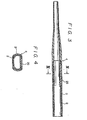
- Fig. 3 shows the casing molded in this way
- Fig. 4 shows a cross-section taken along lines IV-IV in Fig. 3.
- the casing 4 has a tip portion 4A on which is fitted the probe cap 51 covering the slender, extended front end portion 5 of the thermometer.
- the outer periphery of the tip portion 4A is formed to include three annular ribs 4B each having a diameter which gradually increases from the front end toward the back end of the casing, thus providing each rib 4B with a generally flared configuration.
- Each rib 4B has an outer edge portion 4C the diameter whereof is slightly larger than the inner diameter of the probe cap 51.
- Fig. 6 depicts the probe cap 51 fitted over the tip portion 4A to cover the ribs-4B.
- the outer edge portion 4C of each rib 4B where it contacts the inner surface of the probe cap 51 is deformed and flattened, so that the cap 51 fits snugly on the tip portion 4A without leaving any gaps between each rib 4B and the inner surface of the cap.
- annular air-filled chambers 60 are formed between the cap 51 and the tip portion 4A.
- the probe cap 51 is connected to the tip portion 4A liquid tightly, and liquids will not flow or seep into the thermometer through capillary action so long as the air chambers 60 remain intact.
- the potting material 55 filling the interior of the probe cap contributes to the liquid-tight integrity of the probe cap structure. This assures that the joint between the probe cap 51 and the casing 4 will be waterproof.
- ribs 4B are necessary to form the air-filled chamber 60. Increasing the number of ribs 4B produces a greater number of the air-filled chambers 60, thus affording a correspondingly higher degree of liquid tightness.
- the electronic clinical thermometer of the present invention was soaked for two weeks in aqueous solutions of ethanol, hypal No.20 from Dai Nihon Seiyaku K.K, hibitane (chlorhexidine gluconate) from ICI Pharma K .K, tekysant (sodium hypochlorite) from SHIOE Seiyaku K.K, commercially available diamidol (benzalkonium chloride) and milton.
- the experimental results revealed absolutely no failure or loss in precision by the thermister.
- thermometers in accordance with the present invention were soaked for 5 min in an aqueous solution of 0.02% hibitane at a temperature of 55°C. Each thermometer was then extracted from the solution and dried for 5 min. This procedure was repeated for each thermometer to determine the sealing property and waterproofness of the thermometers based on the failure rate (including any deterioration in precision) of the thermometers. The results are shown in the following table.
- the annular air-filled chambers 60 are formed at the joint between the metal probe cap 51 and the casing 4, thus preventing the intrusion of liquid through capillary action when the thermometer is sterilized or washed. This assures that the precision of the thermometer will not be adversely influenced by the invasion of liquid.
- the temperature display window 25 is formed without using an adhesive, as in the prior art. And -since the display window 25 and casing 4 are integrally formed by multiple-color injection molding, the liquidproof properties of the thermometer obtained are excellent.
- the thermometer can be assembled in a simple manner merely by press-fitting the metal cap 51 onto the end of the casing without use of an adhesive. This provides an electronic clinical thermometer with excellent thermal contact between the metal cap 51 and the temperature sensing element 9.
Abstract
Description
- This invention relates to an electronic clinical thermometer, of approximately the same size as a mercury thermometer and having a water-tight casing, for sensing body temperature electronically and for displaying the temperature in digital form.
- An electronic clinical thermometer typically comprises a temperature sensing element which converts body temperature information into an electric signal, a measuring unit for converting the electric signal from the temperature sensing element into a digital signal, an arithmetic unit for computing body temperature from the digital signal, a display unit for displaying the temperature computed by the arithmetic unit, a battery for supplying the abovementioned components with electric power, and a plastic casing for housing these components.
- With the minaturization of LSIs and other electronic components, circuit techniques have made it possible to achieve a significant reduction in the size of electronic clinical thermometers of the foregoing type. When such thermometers are used at institutions such as hospitals and clinics, a treatment such as sterilization or washing of the outer surface of the thermometer is essential in order to prevent the transmission of infection among patients through the medium of the thermometer. Clinical electronic thermometers having a watertight structure which permits such sterilization and washing are now available.
- Since the casing of an electronic thermometer includes a number of joints at the location of such parts as a transparent plastic display window through which body temperature is read and a metal cap situated at the tip of the thermometer, it is necessary that these joints be made watertight in order to realize a waterproof structure. To this end, the inventor has succeeded in integrally molding such portions as the display window with the casing proper by a multiple-color injection molding technique, thereby obtaining a perfect waterproof property at these portions. However, achieving a waterproof condition at the temperature sensing tip of the thermometer covered by the metal cap has presented problems. Specifically, the conventional metal cap is attached to the extended, slender tip of the casing by using an adhesive. Since the adhesive cannot be applied evenly and smoothly between the metal cap and the casing, local gaps are formed that allow aqueous solutions to flow into or infiltrate the interior of the casing owing to such phenomena as capillary action. Furthermore, the metal cap tends to separate from the adhesive due to thermal expansion and contraction of the adhesive caused by changes in the outside temperature. This allow aqueous solutions to seep in through small voids which develop between the adhesive and cap.
- The foregoing inflow or infiltration of aqueous solutions results in the moisture-induced malfunction of, e.g., a thermister serving as the thermometer temperature sensor. Another drawback is the trouble involved in assembling the thermometer owing to use of the adhesive.
- An object of the present invention is to provide an electronic clinical thermometer having an improved waterproof property in which the infiltration of water as by capillary action is prevented by providing an air-filled chamber between the thermometer casing and the metal cap covering the tip of the casing without the use of an adhesive.
- Another object of the present invention is to provide an electronic clinical thermometer formed to include a temperature display window without use of an adhesive.
- Still another object of the present invention is to provide an electronic clinical thermometer having a temperature display window that can be formed with facility.
- Still another object of the present invention is to provide an electronic clinical thermometer adapted to prevent the inflow or infiltration of liquids from a temperature display window.
- A further object of the present invention is to provide an electronic clinical thermometer capable of being. assembled by the press-fitting of the metal cap without use of an adhesive.
- A yet further object of the present invention is to provide an electronic clinical thermometer featuring improved thermal conduction between the metal cap and a temperature sensing element, as well as improved impact resistance for the temperature sensing element.
- According to the present invention, the foregoing objects are attained by providing an electronic clinical thermometer comprising an elongate casing having an extended slender tip at an end thereof, a metal cap covering a distal end of the extended slender tip, a temperature sensing unit arranged inside the metal cap, electronic circuit means connected to the temperature sensing unit for detecting temperature, and a battery housed in the elongated casing for supplying the electronic circuit means with electric power, the distal end of the extended slender tip having an outer periphery provided with at least two annular ribs, an air-filled chamber being formed between the annular ribs and an inner surface of the metal cap when the annular ribs are covered by the metal cap.
- In a preferred embodiment of the present invention, the air-filled chamber is annular in shape and extends toward the distal end of the extended slender tip. The casing comprises an inner case body molded from a transparent resin and an outer case body molded from an opaque resin, the inner case body and the outer case body being formed integral with each other by multiple-color injection molding. The outer case body is partially cut away to form a temperature display window or, alternatively, the inner case body is watertightly formed to include a temperature display window.
- The metal cap has an inner diameter smaller than the outer diameter of the annular ribs. The outer diameter of each of the annular ribs is gradually larger in a direction coinciding with a direction in which the metal cap is fitted onto the distal end of the extended slender tip.
- A thermally conductive potting material is filled in a space between the metal cap and the temperature sensing unit. A temperature sensing element is fixed inside the potting material. The temperature sensing element is a thermister.
- Other features and advantages of the present invention will be apparent from the following description taken in conjunction with the accompanying drawings, in which like reference characters designate the same or similar parts throughout the figures thereof.
-
- Fig. 1 is a perspective view illustrating a preferred embodiment of an electronic clinical thermometer according to the present invention;
- Fig. 2 is a longitudinal sectional view of the thermometer shown in Fig. 1;
- Fig. 3 is a longitudinal sectional view showing a casing in Fig. 2 after the completion of a molding process;
- Fig. 4 is a sectional view taken along line IV-IV of Fig. 3;
- Fig. 5 is an enlarged sectional view showing a distal end portion of a casing constituting the electronic clinical thermometer of Fig. 1; and
- Fig. 6 is an enlarged sectional view showing a metal probe cap press-fitted onto the distal end portion of the casing.
- Turning now to the drawings and referring first particularly to Figs. 1 through 5, an electronic clinical thermometer embodying the present invention indicated generally by the reference numeral 1 includes an
elongated casing 4 comprising a transparentinner case body 2 and anouter case body 3. In the illustrated embodiment the transparentinner case body 2 is molded in the form of a cylindrical body by using a multiple-color injection molding machine. Theouter case body 3 is then molded from an opaque resin so as to cover the outer surface of theinner case body 2 forming thecasing 4. Theouter case body 3 is provided with adisplay window 25. - The
outer case body 3 is extended longitudinally to form a slender tip at one end of thecasing 4, this end being referred to as a probe end. The distal end of the slender tip is provided with a temperature sensing unit, and ametal probe cap 51 for protecting the temperature sensing unit. The other or base end of thecasing 4 is closed by arear cap 81 attached to the casing via abattery holder 85. - As shown in Fig. 2, the electronic clinical thermometer 1 includes a
temperature sensing element 9 such as a thermister constituting part of the aforementioned temperature sensing unit for converting body temperature information into an electric signal. Theelement 9 is housed inside thecasing 4 at the probe end thereof and is connected to electronic circuit elements including an arithmetic unit 6 powered by a battery 8 accommodated in thebattery holder 85. The arithmetic unit 6 converts the electric signal from thetemperature sensing element 9 into a digital signal and processes the digital signal so that the sensed temperature may be displayed by adisplay unit 7. The arithmetic unit 6 may be constituted by known measurement circuitry for providing a direct reading of temperature or for predicting final temperature. Connected between the arithmetic unit 6 and battery 8 is a switching means, not shown, utilizing a magnet reed relay or the like. - For a detailed discussion of the arithmetic unit 6 and
display unit 7, not given here, reference should be made to the specifications of U.S. Serial Nos. 418,287 (July 24, 1984), 454, 020 (December 28, 1982), 504,235 (June 14, 1983), and 561,181 (December 14, 1983). - The arithmetic unit 6,
display unit 7, battery 8 andtemperature sensing element 9 are housed in thecasing 4. - Covering the distal or probe end of the
casing 4 is theprobe cap 51, made of a metal such as stainless steel aluminum. A portingmaterial 55 fills the interior of the distal end ofcasing 4 around the periphery of thetemperature sensing element 9 and serves to improve the thermal conduction between thetemperature sensing element 9 and theprobe cap 51 covering it. - The battery 8 housed in the
battery holder 85 at the base end of thecasing 4 is retained by therear cap 81 bonded to thebattery holder 85 by an adhesive. The bond can also be achieved by ultrasonic sealing if proper selection of plastic materials is made. - In such case the
outer case body 3 constituting thecasing 4, therear cap 81 and thebattery holder 85 are formed of an opaque resin, or a resin made opaque by coloring. Examples of such resins are polyethers such as polyphenylene oxide, polyesters such as polyethylene terephthalate and polybutylene terephthalate, acrylic resins such as polyacetal and polymethyl methacrylate, polystyrene resins such as ABS resin, polyolefins such as poly-2-methylpentene and polypropylene, and polycarbonate resin. - The
inner case body 2 is formed of a transparent resin. Examples are polystyrene resins such as polystyrene, polyolefins such as poly-2-methylpentene and polypropylene, acrylic resins such as polymethyl methacrylate, cellulose esters such as cellulose acetate, and polyesters such as polyethylene terephthalate. - As mentioned above, the
probe cap 51 is made of a metal such as stainless steel or aluminum. - By using the above materials, excellent results can be obtained if the
inner case body 2 made of the transparent resin and theouter case body 3 made of. the opaque resin are formed integral with each other so that theouter case body 3 contacts thedisplay window 25 of theinner case body 2 liquid tightly. Accordingly, theinner case body 2 can be formed to have a plate-like configuration rather than the cylindrical configuration mentioned above. However, it is preferred that a so-called two-color injection molding operation using a molding machine be adopted to integrate the twocase bodies inner case body 2 is preferred since this will widen the area of liquid-tight contact and, hence, provide an even greater degree of waterproofness. - The
display window 25 is formed on the outer side of theinner case body 2 having the cylindrical configuration. It is preferred that thedisplay window 25 be of generally trapzoidal form projecting outwardly from thecylindrical case body 2, as shown in Figs. 2 through 4. Adopting such an arrangement provides the rim of thewindow 25 with a step-like portion engaged by the opaqueresin case body 3 to form an excellent connection between the two. - A multiple-color injection molding machine, specifically a two-color injection molding machine in the illustrated embodiment, is used to mold the
casing 4. The molding process includes molding the cylindricalinner case body 2 and then molding theouter case body 3 to cover the outer surface of theinner case body 2, whereby thecase bodies - As is well known in the field of plastic molding, the multiple molding process refered to in this specification is performed using injection molding techniques. Therefore, we will describe how these techniques are used to carry out the two-color injection molding process.
- A primary injection molding device has a mold including a cavity of a shape which corresponds to the outer wall of the
inner case body 2 and a core of a shape which corresponds to the inner wall of thecasing 4. Any suitable transparent resin is injected into the mold cavity of the primary injection molding machine. The resultinginner case body 2 together with the core is taken out of the cavity and turned toward a secondary injection molding device. - The secondary injection molding device has a mold defining a cavity of a shape which corresponds to the outer surface of the
outer case body 3. The core having the transparentinner case body 2 molded thereon is inserted into the cavity, and a suitable opaque resin is then injected into the cavity. The injected opaque resin intimately contacts or adheres to theinner case body 2 except at thedisplay window 25. Theinner case body 2 is thus tightly joined with theouter case body 3 to form a distinctive, but one-piece casing. That is, theinner case body 2 is integrated with theouter case body 3 into a unit, but the distinctive characteristics of each of the plastics are uneffected. The thus integrally moldedcasing 4 is removed from the cavity together with the core and the -core is then removed, obtaining thecasing 4 which consists of theinner case body 2 and theouter case body 3 mutually integrated. - Fig. 3 shows the casing molded in this way, and Fig. 4 shows a cross-section taken along lines IV-IV in Fig. 3.
- The structure for attaching the
probe cap 51 to the distal end of the electronic thermometer 1 will now be described with reference to Figs. 5 and 6. - As shown in Fig. 5, the
casing 4 has atip portion 4A on which is fitted theprobe cap 51 covering the slender, extendedfront end portion 5 of the thermometer. The outer periphery of thetip portion 4A is formed to include threeannular ribs 4B each having a diameter which gradually increases from the front end toward the back end of the casing, thus providing eachrib 4B with a generally flared configuration. Eachrib 4B has anouter edge portion 4C the diameter whereof is slightly larger than the inner diameter of theprobe cap 51. - Fig. 6 depicts the
probe cap 51 fitted over thetip portion 4A to cover the ribs-4B. As shown, theouter edge portion 4C of eachrib 4B where it contacts the inner surface of theprobe cap 51 is deformed and flattened, so that thecap 51 fits snugly on thetip portion 4A without leaving any gaps between eachrib 4B and the inner surface of the cap. Owing to this pressured contact between theribs 4B and the inner-surface of thecap 51, annular air-filledchambers 60 are formed between thecap 51 and thetip portion 4A. By virtue of this structure, theprobe cap 51 is connected to thetip portion 4A liquid tightly, and liquids will not flow or seep into the thermometer through capillary action so long as theair chambers 60 remain intact. The pottingmaterial 55 filling the interior of the probe cap contributes to the liquid-tight integrity of the probe cap structure. This assures that the joint between theprobe cap 51 and thecasing 4 will be waterproof. - It should be noted that at least two
ribs 4B are necessary to form the air-filledchamber 60. Increasing the number ofribs 4B produces a greater number of the air-filledchambers 60, thus affording a correspondingly higher degree of liquid tightness. - Let us now describe experiments conducted to ascertain the liquid-tightness of the connection between the
probe cap 51 and thecasing 4 of the electronic clinical thermometer according to the present invention. - To check for thermister malfunction caused by infiltration of liquid at the joint of the probe cap 15, the electronic clinical thermometer of the present invention was soaked for two weeks in aqueous solutions of ethanol, hypal No.20 from Dai Nihon Seiyaku K.K, hibitane (chlorhexidine gluconate) from ICI Pharma K.K, tekysant (sodium hypochlorite) from SHIOE Seiyaku K.K, commercially available diamidol (benzalkonium chloride) and milton. The experimental results revealed absolutely no failure or loss in precision by the thermister.
- One hundred electronic clinical thermometers in accordance with the present invention and the same number of conventional electronic clinical thermometers having electronic circuitry identical with that of the present invention and using an adhesive to attach the probe cap were soaked for 5 min in an aqueous solution of 0.02% hibitane at a temperature of 55°C. Each thermometer was then extracted from the solution and dried for 5 min. This procedure was repeated for each thermometer to determine the sealing property and waterproofness of the thermometers based on the failure rate (including any deterioration in precision) of the thermometers. The results are shown in the following table.

- These results demonstrate that the liquidproof properties and durability of the electronic clinical thermometer of the present invention are excellent.
- According to the present invention, the annular air-filled
chambers 60 are formed at the joint between themetal probe cap 51 and thecasing 4, thus preventing the intrusion of liquid through capillary action when the thermometer is sterilized or washed. This assures that the precision of the thermometer will not be adversely influenced by the invasion of liquid. In addition, thetemperature display window 25 is formed without using an adhesive, as in the prior art. And -since thedisplay window 25 andcasing 4 are integrally formed by multiple-color injection molding, the liquidproof properties of the thermometer obtained are excellent. Furthermore, the thermometer can be assembled in a simple manner merely by press-fitting themetal cap 51 onto the end of the casing without use of an adhesive. This provides an electronic clinical thermometer with excellent thermal contact between themetal cap 51 and thetemperature sensing element 9. - As many apparently widely different embodiments of the present invention can be made without departing from the spirit and scope thereof, it is to be understood that the invention is not limited to the specific embodiments thereof except as defined in the appended claims.
Claims (14)
Applications Claiming Priority (2)
| Application Number | Priority Date | Filing Date | Title |
|---|---|---|---|
| JP59232297A JPS61111428A (en) | 1984-11-06 | 1984-11-06 | Electronic clinical thermometer |
| JP232297/84 | 1984-11-06 |
Publications (3)
| Publication Number | Publication Date |
|---|---|
| EP0180951A2 true EP0180951A2 (en) | 1986-05-14 |
| EP0180951A3 EP0180951A3 (en) | 1987-06-16 |
| EP0180951B1 EP0180951B1 (en) | 1990-09-12 |
Family
ID=16937007
Family Applications (1)
| Application Number | Title | Priority Date | Filing Date |
|---|---|---|---|
| EP85114000A Expired - Lifetime EP0180951B1 (en) | 1984-11-06 | 1985-11-04 | Electronic clinical thermometer |
Country Status (5)
| Country | Link |
|---|---|
| US (1) | US4729672A (en) |
| EP (1) | EP0180951B1 (en) |
| JP (1) | JPS61111428A (en) |
| CA (1) | CA1260291A (en) |
| DE (1) | DE3579667D1 (en) |
Cited By (5)
| Publication number | Priority date | Publication date | Assignee | Title |
|---|---|---|---|---|
| EP0360025A2 (en) * | 1988-08-25 | 1990-03-28 | Terumo Kabushiki Kaisha | Temperature measuring probe and electronic clinical thermometer equipped with same |
| EP0458420A2 (en) * | 1990-05-25 | 1991-11-27 | Citizen Watch Co., Ltd. | Electronic clinical thermometer |
| US5149200A (en) * | 1988-08-25 | 1992-09-22 | Terumo Kabushiki Kaisha | Temperature measuring probe and electronic clinical thermometer equipped with same |
| US5178468A (en) * | 1988-08-25 | 1993-01-12 | Terumo Kabushiki Kaisha | Temperature measuring probe and electronic clinical thermometer equipped with same |
| EP1054239A1 (en) * | 1999-05-20 | 2000-11-22 | Testo GmbH & Co. | Control- and display device |
Families Citing this family (66)
| Publication number | Priority date | Publication date | Assignee | Title |
|---|---|---|---|---|
| US5133606A (en) * | 1989-07-28 | 1992-07-28 | Becton, Dickinson And Company | Electronic clinical thermometer |
| US5013161A (en) * | 1989-07-28 | 1991-05-07 | Becton, Dickinson And Company | Electronic clinical thermometer |
| US5022766A (en) * | 1990-01-19 | 1991-06-11 | Phipps Jack M | Temperature sensing device |
| US5277496A (en) * | 1990-10-17 | 1994-01-11 | Ametek, Inc. | High temperature optical probe |
| DE69613213T2 (en) * | 1995-02-02 | 2001-10-04 | Keystone Thermometrics Corp | TEMPERATURE PROBE |
| US5741074A (en) * | 1995-06-06 | 1998-04-21 | Thermo Electrioc Corporation | Linear integrated sensing transmitter sensor |
| USD385203S (en) * | 1995-12-08 | 1997-10-21 | Polymedica Industries, Inc. | Digital thermometer |
| US6379039B1 (en) | 1997-11-12 | 2002-04-30 | K-Jump Health Co., Ltd. | Cost-effective electronic thermometer |
| US6068399A (en) * | 1997-11-12 | 2000-05-30 | K-Jump Health Co., Ltd. | Cost-effective electronic thermometer |
| JP2000111414A (en) * | 1998-10-09 | 2000-04-21 | Hyakuryaku Kigyo Kofun Yugenkoshi | Clinical thermometer |
| DE29820206U1 (en) * | 1998-11-11 | 1999-02-25 | Microlife Medical Science Asia | Electronic clinical thermometer |
| USD420924S (en) * | 1999-02-01 | 2000-02-22 | Kjump Health Co., Ltd. | Digital thermometer |
| US6338571B1 (en) * | 2000-02-03 | 2002-01-15 | Min-Ying Chen | Rapid heat conducting structure of an electronic thermometer |
| EP1182437A1 (en) * | 2000-08-23 | 2002-02-27 | Microlife Intellectual Property GmbH | Medical thermometer and method for producing a medical thermometer |
| US6773405B2 (en) | 2000-09-15 | 2004-08-10 | Jacob Fraden | Ear temperature monitor and method of temperature measurement |
| US6839651B2 (en) | 2001-06-27 | 2005-01-04 | Sherwood Services Ag | Probe tip thermal isolation and fast prediction algorithm |
| WO2003040673A2 (en) | 2001-11-02 | 2003-05-15 | Phipps Jack M | Temperature sensor with enhanced ambient air temperature detection |
| WO2003044477A1 (en) * | 2001-11-20 | 2003-05-30 | Citizen Watch Co., Ltd. | Thermometer |
| US6637935B2 (en) * | 2002-01-08 | 2003-10-28 | Min-Ying Chen | Structure of a clinical thermometer |
| US7381184B2 (en) | 2002-11-05 | 2008-06-03 | Abbott Diabetes Care Inc. | Sensor inserter assembly |
| US6981796B2 (en) * | 2002-12-04 | 2006-01-03 | Actherm Inc. | Electronic thermometer |
| US6957911B2 (en) | 2003-06-24 | 2005-10-25 | Cosco Management, Inc. | Infant thermometer |
| US7938783B2 (en) * | 2003-08-19 | 2011-05-10 | Advanced Monitors Corporation | Medical body core thermometer |
| US7785266B2 (en) | 2003-08-19 | 2010-08-31 | Advanced Monitors Corporation | Medical thermometer for determining body core temperature |
| USD902408S1 (en) | 2003-11-05 | 2020-11-17 | Abbott Diabetes Care Inc. | Analyte sensor control unit |
| US7731657B2 (en) | 2005-08-30 | 2010-06-08 | Abbott Diabetes Care Inc. | Analyte sensor introducer and methods of use |
| US8512243B2 (en) | 2005-09-30 | 2013-08-20 | Abbott Diabetes Care Inc. | Integrated introducer and transmitter assembly and methods of use |
| US8613703B2 (en) | 2007-05-31 | 2013-12-24 | Abbott Diabetes Care Inc. | Insertion devices and methods |
| US9743862B2 (en) | 2011-03-31 | 2017-08-29 | Abbott Diabetes Care Inc. | Systems and methods for transcutaneously implanting medical devices |
| US9398882B2 (en) | 2005-09-30 | 2016-07-26 | Abbott Diabetes Care Inc. | Method and apparatus for providing analyte sensor and data processing device |
| US10226207B2 (en) | 2004-12-29 | 2019-03-12 | Abbott Diabetes Care Inc. | Sensor inserter having introducer |
| US9259175B2 (en) | 2006-10-23 | 2016-02-16 | Abbott Diabetes Care, Inc. | Flexible patch for fluid delivery and monitoring body analytes |
| US8571624B2 (en) | 2004-12-29 | 2013-10-29 | Abbott Diabetes Care Inc. | Method and apparatus for mounting a data transmission device in a communication system |
| US9788771B2 (en) * | 2006-10-23 | 2017-10-17 | Abbott Diabetes Care Inc. | Variable speed sensor insertion devices and methods of use |
| US20090082693A1 (en) * | 2004-12-29 | 2009-03-26 | Therasense, Inc. | Method and apparatus for providing temperature sensor module in a data communication system |
| US20090105569A1 (en) | 2006-04-28 | 2009-04-23 | Abbott Diabetes Care, Inc. | Introducer Assembly and Methods of Use |
| US9572534B2 (en) | 2010-06-29 | 2017-02-21 | Abbott Diabetes Care Inc. | Devices, systems and methods for on-skin or on-body mounting of medical devices |
| US8333714B2 (en) | 2006-09-10 | 2012-12-18 | Abbott Diabetes Care Inc. | Method and system for providing an integrated analyte sensor insertion device and data processing unit |
| US7697967B2 (en) | 2005-12-28 | 2010-04-13 | Abbott Diabetes Care Inc. | Method and apparatus for providing analyte sensor insertion |
| US7883464B2 (en) | 2005-09-30 | 2011-02-08 | Abbott Diabetes Care Inc. | Integrated transmitter unit and sensor introducer mechanism and methods of use |
| US9351669B2 (en) | 2009-09-30 | 2016-05-31 | Abbott Diabetes Care Inc. | Interconnect for on-body analyte monitoring device |
| JP4214124B2 (en) * | 2005-03-14 | 2009-01-28 | 株式会社バイオエコーネット | Ear thermometer |
| DE102006022620B4 (en) * | 2005-08-19 | 2014-05-22 | Otto Egelhof Gmbh & Co. Kg | temperature sensor |
| US9521968B2 (en) | 2005-09-30 | 2016-12-20 | Abbott Diabetes Care Inc. | Analyte sensor retention mechanism and methods of use |
| US7316507B2 (en) * | 2005-11-03 | 2008-01-08 | Covidien Ag | Electronic thermometer with flex circuit location |
| US20070100253A1 (en) * | 2005-11-03 | 2007-05-03 | Sherwood Services Ag | Electronic thermometer with sensor location |
| CA2636034A1 (en) | 2005-12-28 | 2007-10-25 | Abbott Diabetes Care Inc. | Medical device insertion |
| US11298058B2 (en) | 2005-12-28 | 2022-04-12 | Abbott Diabetes Care Inc. | Method and apparatus for providing analyte sensor insertion |
| US7303333B2 (en) * | 2006-04-21 | 2007-12-04 | Mesure Technology Co., Ltd. | Thermometer with soft flexible probe |
| US7749170B2 (en) | 2007-05-22 | 2010-07-06 | Tyco Healthcare Group Lp | Multiple configurable electronic thermometer |
| US8059947B2 (en) * | 2007-10-29 | 2011-11-15 | Smiths Medical Asd, Inc. | Environmentally protected thermistor for respiratory system |
| US8303173B2 (en) * | 2007-10-29 | 2012-11-06 | Smiths Medical Asd, Inc. | Dual potting temperature probe |
| US8496377B2 (en) | 2007-12-31 | 2013-07-30 | Covidien Lp | Thermometer having molded probe component |
| DE102008029192A1 (en) * | 2008-03-13 | 2009-09-24 | Epcos Ag | Sensor for detecting a physical quantity and method for manufacturing the sensor |
| US9402544B2 (en) | 2009-02-03 | 2016-08-02 | Abbott Diabetes Care Inc. | Analyte sensor and apparatus for insertion of the sensor |
| US8613892B2 (en) | 2009-06-30 | 2013-12-24 | Abbott Diabetes Care Inc. | Analyte meter with a moveable head and methods of using the same |
| USD924406S1 (en) | 2010-02-01 | 2021-07-06 | Abbott Diabetes Care Inc. | Analyte sensor inserter |
| EP4245220A3 (en) | 2010-03-24 | 2023-12-20 | Abbott Diabetes Care, Inc. | Medical device inserters |
| US11064921B2 (en) | 2010-06-29 | 2021-07-20 | Abbott Diabetes Care Inc. | Devices, systems and methods for on-skin or on-body mounting of medical devices |
| CA2840642C (en) | 2011-12-11 | 2022-01-18 | Abbott Diabetes Care Inc. | Analyte sensor devices, connections, and methods |
| US10213139B2 (en) | 2015-05-14 | 2019-02-26 | Abbott Diabetes Care Inc. | Systems, devices, and methods for assembling an applicator and sensor control device |
| WO2016183493A1 (en) | 2015-05-14 | 2016-11-17 | Abbott Diabetes Care Inc. | Compact medical device inserters and related systems and methods |
| WO2018136898A1 (en) | 2017-01-23 | 2018-07-26 | Abbott Diabetes Care Inc. | Systems, devices and methods for analyte sensor insertion |
| US11274978B2 (en) * | 2017-11-01 | 2022-03-15 | Medline Industries Lp | Tapered thermal probe cover and corresponding packaging system |
| JP1688084S (en) * | 2020-12-02 | 2021-06-21 | Electronic thermometer with wireless communication device | |
| JP1688085S (en) * | 2020-12-02 | 2021-06-21 | Electronic thermometer with wireless communication device |
Citations (5)
| Publication number | Priority date | Publication date | Assignee | Title |
|---|---|---|---|---|
| CH399774A (en) * | 1962-01-16 | 1965-09-30 | Ciba Geigy | Resistance thermometer sensors and process for their manufacture |
| US3832669A (en) * | 1970-08-10 | 1974-08-27 | Royal Medical Corp | Temperature-sensing device |
| GB2108890A (en) * | 1981-10-06 | 1983-05-25 | Flextank Limited | Container having a light transmissive region |
| JPS59116519A (en) * | 1982-12-20 | 1984-07-05 | Kyushu Hitachi Maxell Ltd | Electronic clinical thermometer |
| JPS60219526A (en) * | 1984-04-16 | 1985-11-02 | Terumo Corp | Electronic clinical thermometer and its preparation |
Family Cites Families (21)
| Publication number | Priority date | Publication date | Assignee | Title |
|---|---|---|---|---|
| DE929332C (en) * | 1952-03-25 | 1955-06-23 | Askania Werke Ag | Thermometer, especially as a temperature sensor for regulators serving electrical thermometers, such. B. resistance thermometer, thermocouple or the like. |
| US2753714A (en) * | 1953-07-21 | 1956-07-10 | Perkins | Electric thermometer |
| US2938385A (en) * | 1955-06-23 | 1960-05-31 | Design Inc | Thermistor thermometer system |
| US3016722A (en) * | 1959-05-26 | 1962-01-16 | Ford Motor Co | Slip joint seal |
| US3046028A (en) * | 1959-12-01 | 1962-07-24 | Hamilton Kent Mfg Company | Gasket and use thereof |
| US3367186A (en) * | 1965-08-27 | 1968-02-06 | Measurement Science Corp | Resistance thermometer |
| US3578027A (en) * | 1969-07-30 | 1971-05-11 | William L Zopfi | Sealing plugs or closures |
| US3822598A (en) * | 1971-03-23 | 1974-07-09 | Barge Inc | Portable electronic thermometer and method of temperature measurement |
| US4095810A (en) * | 1977-01-17 | 1978-06-20 | Baxter Travenol Laboratories, Inc. | Gill-type tip protector for sealing open tubes and the like |
| JPS5490441A (en) * | 1977-12-02 | 1979-07-18 | Jiee Etsuchi Fuennaa Ando Co L | Improvement in seal |
| DE2754090A1 (en) * | 1977-12-05 | 1979-06-13 | Peter Boehner | Clinical thermometer with digital read=out - has sensor connected to self-contained electronic circuit |
| JPS55111236A (en) * | 1979-02-20 | 1980-08-27 | Katashi Aoki | Injection/stretching/blowing molding machine for two-layer molding |
| US4492548A (en) * | 1980-02-15 | 1985-01-08 | Rjr Archer, Inc. | Machinery for molding headpiece for collapsible tube including a chilled wiper |
| US4343480A (en) * | 1980-06-23 | 1982-08-10 | Vassallo Efrain D | Pipe bell and gasket |
| JPS58106427A (en) * | 1981-12-18 | 1983-06-24 | Terumo Corp | Electronic clinical thermometer |
| JPS58190734A (en) * | 1982-04-30 | 1983-11-07 | Matsushita Electric Works Ltd | Probe of electronic thermometer |
| JPS5939528A (en) * | 1982-08-31 | 1984-03-03 | Katashi Aoki | Injection molding method and apparatus for composite parison |
| DE3300733A1 (en) * | 1983-01-12 | 1984-07-12 | Robert Bosch Gmbh, 7000 Stuttgart | TEMPERATURE PROBE |
| JPS6080730A (en) * | 1983-10-12 | 1985-05-08 | Terumo Corp | Electronic clinical thermometer |
| US4560973A (en) * | 1983-11-15 | 1985-12-24 | Daimler-Benz Aktiengesellschaft | Rod shaped thermometer and method of making same |
| JPS60131432A (en) * | 1983-12-20 | 1985-07-13 | Terumo Corp | Manufacture of electronic clinical thermometer |
-
1984
- 1984-11-06 JP JP59232297A patent/JPS61111428A/en active Granted
-
1985
- 1985-10-29 US US06/792,542 patent/US4729672A/en not_active Expired - Fee Related
- 1985-11-04 EP EP85114000A patent/EP0180951B1/en not_active Expired - Lifetime
- 1985-11-04 DE DE8585114000T patent/DE3579667D1/en not_active Expired - Fee Related
- 1985-11-05 CA CA000494623A patent/CA1260291A/en not_active Expired
Patent Citations (5)
| Publication number | Priority date | Publication date | Assignee | Title |
|---|---|---|---|---|
| CH399774A (en) * | 1962-01-16 | 1965-09-30 | Ciba Geigy | Resistance thermometer sensors and process for their manufacture |
| US3832669A (en) * | 1970-08-10 | 1974-08-27 | Royal Medical Corp | Temperature-sensing device |
| GB2108890A (en) * | 1981-10-06 | 1983-05-25 | Flextank Limited | Container having a light transmissive region |
| JPS59116519A (en) * | 1982-12-20 | 1984-07-05 | Kyushu Hitachi Maxell Ltd | Electronic clinical thermometer |
| JPS60219526A (en) * | 1984-04-16 | 1985-11-02 | Terumo Corp | Electronic clinical thermometer and its preparation |
Non-Patent Citations (2)
| Title |
|---|
| PATENT ABSTRACTS OF JAPAN, vol. 10, no. 84 (P-442)[2141], 3rd April 1986; & JP-A-60 219 526 (TERUMO K.K.) 02-11-1985 * |
| PATENT ABSTRACTS OF JAPAN, vol. 8, no. 242 (P-311)[1679], 7th November 1984; & JP-A-59 116 519 (KIYUUSHIYUU HITACHI MAKUSERU K.K.) 05-07-1984 * |
Cited By (10)
| Publication number | Priority date | Publication date | Assignee | Title |
|---|---|---|---|---|
| EP0360025A2 (en) * | 1988-08-25 | 1990-03-28 | Terumo Kabushiki Kaisha | Temperature measuring probe and electronic clinical thermometer equipped with same |
| EP0360025A3 (en) * | 1988-08-25 | 1990-10-24 | Terumo Kabushiki Kaisha | Temperature measuring probe and electronic clinical thermometer equipped with same |
| US5088837A (en) * | 1988-08-25 | 1992-02-18 | Terumo Kabushiki Kaisha | Temperature measuring probe and electronic clinical thermometer equipped with same |
| US5149200A (en) * | 1988-08-25 | 1992-09-22 | Terumo Kabushiki Kaisha | Temperature measuring probe and electronic clinical thermometer equipped with same |
| US5178468A (en) * | 1988-08-25 | 1993-01-12 | Terumo Kabushiki Kaisha | Temperature measuring probe and electronic clinical thermometer equipped with same |
| EP0458420A2 (en) * | 1990-05-25 | 1991-11-27 | Citizen Watch Co., Ltd. | Electronic clinical thermometer |
| EP0458420A3 (en) * | 1990-05-25 | 1992-04-08 | Citizen Watch Co. Ltd. | Electronic clinical thermometer |
| US5165798A (en) * | 1990-05-25 | 1992-11-24 | Citizen Watch Co., Ltd. | Electronic clinical thermometer with soft flexible casing |
| EP1054239A1 (en) * | 1999-05-20 | 2000-11-22 | Testo GmbH & Co. | Control- and display device |
| US6665174B1 (en) | 1999-05-20 | 2003-12-16 | Testo Ag | Control and display device |
Also Published As
| Publication number | Publication date |
|---|---|
| EP0180951A3 (en) | 1987-06-16 |
| CA1260291A (en) | 1989-09-26 |
| DE3579667D1 (en) | 1990-10-18 |
| EP0180951B1 (en) | 1990-09-12 |
| JPH0344649B2 (en) | 1991-07-08 |
| US4729672A (en) | 1988-03-08 |
| JPS61111428A (en) | 1986-05-29 |
Similar Documents
| Publication | Publication Date | Title |
|---|---|---|
| US4729672A (en) | Electronic clinical thermometer | |
| US4743121A (en) | Clinical electrothermometer | |
| EP0458420B1 (en) | Electronic clinical thermometer | |
| US6068399A (en) | Cost-effective electronic thermometer | |
| US5013161A (en) | Electronic clinical thermometer | |
| US4444517A (en) | Electronic clinical thermometer | |
| US20070248144A1 (en) | Thermometer with soft flexible probe | |
| GB2133886A (en) | Fast response temperature sensing probe | |
| JPS6080730A (en) | Electronic clinical thermometer | |
| US6379039B1 (en) | Cost-effective electronic thermometer | |
| US6319448B1 (en) | Process for the production of an apparatus or instrument by overmolding and apparatus or instrument thus obtained | |
| US6851850B1 (en) | Electronic fever thermometer | |
| US20070058691A1 (en) | Electronic thermometer | |
| JPS61124832A (en) | Electronic clinical thermometer | |
| JPH10221176A (en) | Electronic clinical thermometer | |
| JP3101373B2 (en) | Electronic thermometer | |
| JPS61191928A (en) | Electronic thermometer | |
| JP2741422B2 (en) | Waterproof cap for transceiver | |
| CN220588139U (en) | Infant bathtub with temperature display | |
| JP2741421B2 (en) | Waterproof cap for transceiver | |
| JPS5818193Y2 (en) | proximity switch | |
| JP2001242016A (en) | Electronic clinical thermometer | |
| JPH0332991Y2 (en) | ||
| JPH0424427Y2 (en) | ||
| JP2001249055A (en) | Electronic clinical thermometer and manufacturing method |
Legal Events
| Date | Code | Title | Description |
|---|---|---|---|
| PUAI | Public reference made under article 153(3) epc to a published international application that has entered the european phase |
Free format text: ORIGINAL CODE: 0009012 |
|
| 17P | Request for examination filed |
Effective date: 19851129 |
|
| AK | Designated contracting states |
Kind code of ref document: A2 Designated state(s): BE DE FR GB |
|
| PUAL | Search report despatched |
Free format text: ORIGINAL CODE: 0009013 |
|
| AK | Designated contracting states |
Kind code of ref document: A3 Designated state(s): BE DE FR GB |
|
| 17Q | First examination report despatched |
Effective date: 19890522 |
|
| GRAA | (expected) grant |
Free format text: ORIGINAL CODE: 0009210 |
|
| AK | Designated contracting states |
Kind code of ref document: B1 Designated state(s): BE DE FR GB |
|
| ET | Fr: translation filed | ||
| REF | Corresponds to: |
Ref document number: 3579667 Country of ref document: DE Date of ref document: 19901018 |
|
| PLBE | No opposition filed within time limit |
Free format text: ORIGINAL CODE: 0009261 |
|
| STAA | Information on the status of an ep patent application or granted ep patent |
Free format text: STATUS: NO OPPOSITION FILED WITHIN TIME LIMIT |
|
| 26N | No opposition filed | ||
| PGFP | Annual fee paid to national office [announced via postgrant information from national office to epo] |
Ref country code: GB Payment date: 19951026 Year of fee payment: 11 |
|
| PGFP | Annual fee paid to national office [announced via postgrant information from national office to epo] |
Ref country code: FR Payment date: 19951109 Year of fee payment: 11 |
|
| PGFP | Annual fee paid to national office [announced via postgrant information from national office to epo] |
Ref country code: DE Payment date: 19951113 Year of fee payment: 11 |
|
| PGFP | Annual fee paid to national office [announced via postgrant information from national office to epo] |
Ref country code: BE Payment date: 19951213 Year of fee payment: 11 |
|
| PG25 | Lapsed in a contracting state [announced via postgrant information from national office to epo] |
Ref country code: GB Effective date: 19961104 |
|
| PG25 | Lapsed in a contracting state [announced via postgrant information from national office to epo] |
Ref country code: BE Effective date: 19961130 |
|
| BERE | Be: lapsed |
Owner name: TERUMO K.K. TRADING AS TERUMO CORP. Effective date: 19961130 |
|
| GBPC | Gb: european patent ceased through non-payment of renewal fee |
Effective date: 19961104 |
|
| PG25 | Lapsed in a contracting state [announced via postgrant information from national office to epo] |
Ref country code: FR Effective date: 19970731 |
|
| PG25 | Lapsed in a contracting state [announced via postgrant information from national office to epo] |
Ref country code: DE Effective date: 19970801 |
|
| REG | Reference to a national code |
Ref country code: FR Ref legal event code: ST |