EP0186996A2 - Unidirectional second order gradient microphone - Google Patents
Unidirectional second order gradient microphone Download PDFInfo
- Publication number
- EP0186996A2 EP0186996A2 EP85309031A EP85309031A EP0186996A2 EP 0186996 A2 EP0186996 A2 EP 0186996A2 EP 85309031 A EP85309031 A EP 85309031A EP 85309031 A EP85309031 A EP 85309031A EP 0186996 A2 EP0186996 A2 EP 0186996A2
- Authority
- EP
- European Patent Office
- Prior art keywords
- microphones
- baffles
- microphone
- chacterized
- arrangement
- Prior art date
- Legal status (The legal status is an assumption and is not a legal conclusion. Google has not performed a legal analysis and makes no representation as to the accuracy of the status listed.)
- Granted
Links
Images


Classifications
-
- H—ELECTRICITY
- H04—ELECTRIC COMMUNICATION TECHNIQUE
- H04R—LOUDSPEAKERS, MICROPHONES, GRAMOPHONE PICK-UPS OR LIKE ACOUSTIC ELECTROMECHANICAL TRANSDUCERS; DEAF-AID SETS; PUBLIC ADDRESS SYSTEMS
- H04R1/00—Details of transducers, loudspeakers or microphones
- H04R1/02—Casings; Cabinets ; Supports therefor; Mountings therein
- H04R1/04—Structural association of microphone with electric circuitry therefor
-
- H—ELECTRICITY
- H04—ELECTRIC COMMUNICATION TECHNIQUE
- H04R—LOUDSPEAKERS, MICROPHONES, GRAMOPHONE PICK-UPS OR LIKE ACOUSTIC ELECTROMECHANICAL TRANSDUCERS; DEAF-AID SETS; PUBLIC ADDRESS SYSTEMS
- H04R3/00—Circuits for transducers, loudspeakers or microphones
- H04R3/005—Circuits for transducers, loudspeakers or microphones for combining the signals of two or more microphones
-
- H—ELECTRICITY
- H04—ELECTRIC COMMUNICATION TECHNIQUE
- H04R—LOUDSPEAKERS, MICROPHONES, GRAMOPHONE PICK-UPS OR LIKE ACOUSTIC ELECTROMECHANICAL TRANSDUCERS; DEAF-AID SETS; PUBLIC ADDRESS SYSTEMS
- H04R1/00—Details of transducers, loudspeakers or microphones
- H04R1/20—Arrangements for obtaining desired frequency or directional characteristics
- H04R1/32—Arrangements for obtaining desired frequency or directional characteristics for obtaining desired directional characteristic only
- H04R1/40—Arrangements for obtaining desired frequency or directional characteristics for obtaining desired directional characteristic only by combining a number of identical transducers
- H04R1/406—Arrangements for obtaining desired frequency or directional characteristics for obtaining desired directional characteristic only by combining a number of identical transducers microphones
Definitions
- This invention relates to electroacoustic transducers and, more particularly, to a directional microphone with a unidirectional directivity pattern.
- Acoustic transducers with directional characteristics are useful in many applications.
- unidirectional microphones with their relatively large directivity factors are widely used.
- Most of these microphones are first order gradients which exhibit, depending on the construction details, directional characteristics described by (a + cos ⁇ ), where a is a constant and 8 is the angle relative to the rotational axis. Directivity factors ranging up to four can be obtained with such systems.
- the directivity may be improved by utilizing second order gradient microphones. These microphones have a directional pattern given by (a + cos ⁇ )(b + cos 9) and yield maximum directivity factors of nine. Wide utilization of such microphones was impeded by the more complicated design and the reduction of signal to noise when compared with the first order designs.
- a second order gradient microphone with unidirectional sensitivity pattern is obtained by housing each of two commercially available first-order gradient microphones centrally within a baffle.
- the baffles have flat surfaces, are preferably square or circular and have parallel surfaces, the two baffles being parallel to each other.
- the rotational axes of the microphones are arranged to coincide.
- the output signal from one of the microphones is subtracted from the delayed signal output from the other.
- the unidirectional microphone exhibits a directional characteristic which is relatively frequency independent, has a three decibel beam width of the main lobe of ⁇ 4,0 degrees, and exhibits side lobes about fifteen decibels below the main lobe.
- the frequency response of the microphone in its direction of maximum sensitivity is within +3 dB between 0.3 kHz and 4 kHz.
- the equivalent noise level of the microphone amounts to 28 dB SPL.
- the preferred embodiment has a smaller size for the same sensitivity.
- the effective spacing between the two surfaces of each microphone is increased, thus directly increasing the sensitivity of the system without introducing undesirable side effects.
- the preferred embodiment uses simple commercially available first order gradient electret microphones. Any type of first order, small transducer may be used. A signal to noise ratio of about thirty decibels for normal speech level is obtained. There is an extended band width over prior art systems.
- the embodiment is simple to make.
- One immediate application for this invention is in mobile radio which requires high directional sensitivity and small size.
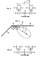
- the unidirectional microphone arrangement comprises two commercial first order gradient bidirectional microphones 14 and 24 such as Knowles model BW-1789 of size 8x4x2 mm 3 or the ATT-Technologies EL-3 electret microphones when the rear cavity is opened to the sound 3ield to form a first order gradient.
- These microphones are placed in openings cut into two square or circular LUCITE, or other plastic, baffles 12 and 22 of size 3x3cm 2 or 3 cm diameter, respectively.
- the gaps between microphones 14 and 24 and baffles 12 and 24 are sealed with epoxy. As shown in FIG.
- baffled microphones 14 and 24 are arranged at a distance of 5 cm apart and are oriented such that the axes of microphones 14 and 24 coincide.
- Microphones 14 and 24 are located in baffles 12 and 22 so that the distance h I from the top of the microphones to the top of the baffles equal the distance h 2 from the bottom of the microphones to the bottom of the baffles.
- the distance 1 1 from one side of the microphones to the nearest edge of the baffles equals the distance from the opposite edge of the microphones to the nearest edges of the baffles.
- the baffles 12 and 22 are suitably supported by a device 18.
- Microphone 14 is shown comprising two sensors: positive sensor 15 and negative sensor 13 separated by a distance d 2 .
- microphone 24 is shown comprising two sensors: positive sensor 25 and negative sensor 23 separated by a distance d 2 .
- Each sensor corresponds to a face of a microphone.
- the distance between the two microphones is d l .
- the microphones are arranged, in one embodiment, so that like polarities face each other.
- a sound radiates from source F.
- the sound will first impinge microphone 24.
- the sound will next travel a distance d 1 to microphone 14 and be returned through delay circuit 20, and, as readily seen, be added with the sound from microphone 24 to derive an output.
- Fig. 2 which has been redrawn to show two separate delay circuits + t, 30, and - t, 35.
- the signal outputs from these delay circuits are then added by circuit 40. If the output signal from one of the microphones is delayed by 2t relative to the other, the sensitivity of the entire system is given by where, M 0 is the sensitivity of each of the sensors 13, 15, 23 and 25, the wave number ⁇ is the angular frequency, c is the velocity of sound, d 3 equals 2ct and ⁇ is the direction of sound incidence relative to the line connecting the sensors. Depending on the ratio of various directional patterns with different directivity indexes are obtained. Two examples are shown in FIG. 5. The design with yields a diredtivity factor of 7.5 while that with yields the highest achievable factor of 8. Directivity factors up to 9 can be achieved by inserting additional delays in the outputs of the individual sensors in FIG. 4.
- Baffles such as 12 and 22 of FIG. 1, are used in the present invention to increase the acoustic path difference between the two sound inlets of each gradient, that is, between the two surfaces (inner and outer) of microphones 14 and 24 by changing the distances h 1 , h 2 , 1 1 , and 1 2 .
- the spacing d 2 in FIG. 4 is determined by the size of baffles 12 and 24 of FIG. 1.
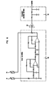
- the output from one of gradient microphones 14 or 24 can be delayed, for example, by a third order Butterworth filter with a delay time of 150 ⁇ s, corresponding to the separation d l between microphones d 14 and 24. By this means, a delay ration of d 3 is 1 obtained.
- Butterworth filter 60, amplifier 62 and low pass filter 64 for correcting the uf frequency dependence are shown in FIG. 6.
- the corresponding theoretical polar pattern for this device is shown in FIG. 5.
- the pattern comprises a main lobe 53 and two small side lobes 55 and 57 which are, if the three dimensional directivity pattern is considered, actually a single deformed toroidal side lobe.
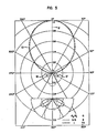
- Measurements on the unidirectional microphone were carried out in an anechoic chamber.
- the microphone was mounted on a B & K model 3922 turntable and exposed to plane and spherical sound fields.
- the results were plotted with a B & K model 2307 level recorder.
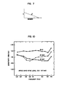
- the output of the microphone was first amplified forty decibels and then passed through a two stage RC filter to correct the w 2 frequency dependence of the second order system as shown in FIC. 's 6 and 7.
- a band pass filter for the range 0.25 through 3.5.kHz, was used to eliminate the out of band noise.
- the figure also shows expected theoretical polar response [ cos ⁇ (1+cos ⁇ )] for the second order unidirectional system chosen here.
- the experimental results are in reasonable agreement with theory.
- the side lobes are only 12 dB down, but 8 dB larger than predicted.
- the microphone has a nonvanishing sensitivity in the backward direction. Inspection of F IG. 5 suggests that this is due to a deviation of from the value of 1 or differences in the frequency and phase response of the first order gradient sensors.
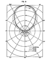
- FIG. 9 shows the polar response for a sound source located at a distance of 0.5 meter. Surprisingly, the directional characteristics are about the same as for the plane wave case. This could be due to poor anechoic conditions.
- the equivalent noise level of the microphone measured for the frequency range 0.25 kHz to 3.5 kHz, is 28 dB.
- FIG. 11 there is shown a directional microphone embodying the present invention located under roof 82 of an automobile near windshield 80 and near the driver who is not shown.
- the microphone arrangement comprises a base 90 having two parallel baffles 92 and 94 housing respectively microphones 91 and 93 in a manner described hereinabove.
- the normal response pattern is shown by lobe 96.
- the dimensions of roof 82 of the car is large in comparison with the wave length of sound in the speech range. This causes lobe 96 to sag and double in intensity, caused by the well known pressure doubling effect.
- the directivity and the size of the lobe is controlled.
- FIG. 12 There is shown in FIG. 12 an alternate arrangement to that shown in FIG. 4 for the microphones 14 and 24 of Fig. 1.
- Sensor 13 of microphone 14 and sensor 25 of microphone 24 are made to face each other. The output signals from microphones 14 and 24 are subtracted in this case. Such an arrangement is needed when the sensors are not truly first order gradients.
Abstract
Description
- This invention relates to electroacoustic transducers and, more particularly, to a directional microphone with a unidirectional directivity pattern.
- Acoustic transducers with directional characteristics are useful in many applications. In particular, unidirectional microphones with their relatively large directivity factors are widely used. Most of these microphones are first order gradients which exhibit, depending on the construction details, directional characteristics described by (a + cos θ), where a is a constant and 8 is the angle relative to the rotational axis. Directivity factors ranging up to four can be obtained with such systems.
- The directivity may be improved by utilizing second order gradient microphones. These microphones have a directional pattern given by (a + cos θ)(b + cos 9) and yield maximum directivity factors of nine. Wide utilization of such microphones was impeded by the more complicated design and the reduction of signal to noise when compared with the first order designs.
- A second order gradient microphone with unidirectional sensitivity pattern is obtained by housing each of two commercially available first-order gradient microphones centrally within a baffle. The baffles have flat surfaces, are preferably square or circular and have parallel surfaces, the two baffles being parallel to each other. The rotational axes of the microphones are arranged to coincide. The output signal from one of the microphones is subtracted from the delayed signal output from the other.
- The unidirectional microphone exhibits a directional characteristic which is relatively frequency independent, has a three decibel beam width of the main lobe of ± 4,0 degrees, and exhibits side lobes about fifteen decibels below the main lobe. After equalization, the frequency response of the microphone in its direction of maximum sensitivity is within +3 dB between 0.3 kHz and 4 kHz. The equivalent noise level of the microphone amounts to 28 dB SPL.
- The following advantages over the prior art are realized with the present invention. The preferred embodiment has a smaller size for the same sensitivity. The effective spacing between the two surfaces of each microphone is increased, thus directly increasing the sensitivity of the system without introducing undesirable side effects. The preferred embodiment uses simple commercially available first order gradient electret microphones. Any type of first order, small transducer may be used. A signal to noise ratio of about thirty decibels for normal speech level is obtained. There is an extended band width over prior art systems. The embodiment is simple to make.
- One immediate application for this invention is in mobile radio which requires high directional sensitivity and small size.
-
- FIG. 1 shows the preferred embodiment of the present invention;
- FIG.'s 2, 3 and 4 are useful in disclosing the principles on which the present invention is based;
- FIG. '
s - FIG.'s 6 and 7 show the signal path,
- FIG. 11 shows an application of the present invention, and
- FIG. 12 shows an alternate arrangement to FIG. 4.
- The preferred embod.iment of the present invention is shown in FIG. 1. The unidirectional microphone arrangement comprises two commercial first order gradient
bidirectional microphones baffles microphones baffles microphones microphones Microphones baffles distance 11 from one side of the microphones to the nearest edge of the baffles equals the distance from the opposite edge of the microphones to the nearest edges of the baffles. Thebaffles - The principle of the present invention will become clear by referring to FIG. 2. Microphone 14 is shown comprising two sensors:
positive sensor 15 andnegative sensor 13 separated by a distance d2. Likewise, microphone 24 is shown comprising two sensors:positive sensor 25 andnegative sensor 23 separated by a distance d2. Each sensor corresponds to a face of a microphone. The distance between the two microphones is dl. The microphones are arranged, in one embodiment, so that like polarities face each other. - Assume a plane sound wave traveling from source B impinges on the device of FIG. 2. The sound will first be picked up by
microphone 14 and then the output from microphone 14 is passed throughdelay circuit 20. After impinging onmicrophone 14, the sound from source B must travel a distance d1 before impingingmicrophone 24. If the delay t is made to equal the distance dl, the sound signals frommicrophones - Assume now that a sound radiates from source F. The sound will first impinge
microphone 24. The sound will next travel a distance d1 tomicrophone 14 and be returned throughdelay circuit 20, and, as readily seen, be added with the sound frommicrophone 24 to derive an output. - Referring to FIG. 4, there is shown Fig. 2 which has been redrawn to show two separate delay circuits + t, 30, and - t, 35. The signal outputs from these delay circuits are then added by
circuit 40. If the output signal from one of the microphones is delayed by 2t relative to the other, the sensitivity of the entire system is given by
sensors 


- Baffles, such as 12 and 22 of FIG. 1, are used in the present invention to increase the acoustic path difference between the two sound inlets of each gradient, that is, between the two surfaces (inner and outer) of
microphones baffles - The output from one of
gradient microphones microphones d Butterworth filter 60,amplifier 62 andlow pass filter 64 for correcting the uf frequency dependence are shown in FIG. 6. The corresponding theoretical polar pattern for this device is shown in FIG. 5. The pattern comprises amain lobe 53 and twosmall side lobes - Measurements on the unidirectional microphone were carried out in an anechoic chamber. The microphone was mounted on a B & K model 3922 turntable and exposed to plane and spherical sound fields. The results were plotted with a B & K model 2307 level recorder.
- The output of the microphone was first amplified forty decibels and then passed through a two stage RC filter to correct the w2 frequency dependence of the second order system as shown in FIC. 's 6 and 7. A band pass filter, for the range 0.25 through 3.5.kHz, was used to eliminate the out of band noise.
- The directional characteristics of the unidirectional microphohe for a plain sound field, source located about two meters from the microphone, are shown in FIG. 8. The figure also shows expected theoretical polar response [


- The performance of such a directional microphone exposed to the sound fields of a sound source at a finite distance is of considerable interest for their use in small noisy spaces. FIG. 9 shows the polar response for a sound source located at a distance of 0.5 meter. Surprisingly, the directional characteristics are about the same as for the plane wave case. This could be due to poor anechoic conditions.
- The corrected frequency responses of the microphone for φ = 0, 90 and 180 degrees are shown in FIG 10 for

- This invention finds use in mobile radio. Referring to FIG. 11, there is shown a directional microphone embodying the present invention located under
roof 82 of an automobile nearwindshield 80 and near the driver who is not shown. The microphone arrangement comprises a base 90 having twoparallel baffles 92 and 94 housing respectivelymicrophones 91 and 93 in a manner described hereinabove. The normal response pattern is shown by lobe 96. The dimensions ofroof 82 of the car is large in comparison with the wave length of sound in the speech range. This causes lobe 96 to sag and double in intensity, caused by the well known pressure doubling effect. As stated hereinabove, by adjusting the dimensions of the baffle the directivity and the size of the lobe is controlled. - There is shown in FIG. 12 an alternate arrangement to that shown in FIG. 4 for the
microphones Sensor 13 ofmicrophone 14 andsensor 25 ofmicrophone 24 are made to face each other. The output signals frommicrophones
Claims (8)
CHACTERIZED BY
said microphones are so placed within said baffles that the sides of said microphones facing each other have the same polarity sensors (13,23 or 15,25).
at least one delay circuit (20) from the output of said first or second microphones.
delay devices (35,30) are connected to each sensor of said first and second microphones to increase the directivity of said arrangement.
the directivity of said arrangement is controlled by the dimensions of said baffle.
said microphones are so placed within said baffles that the sides of said microphones facing each other have the opposite polarity sensors (13,23, Fig. 12).
Applications Claiming Priority (2)
| Application Number | Priority Date | Filing Date | Title |
|---|---|---|---|
| US684575 | 1984-12-20 | ||
| US06/684,575 US4742548A (en) | 1984-12-20 | 1984-12-20 | Unidirectional second order gradient microphone |
Publications (3)
| Publication Number | Publication Date |
|---|---|
| EP0186996A2 true EP0186996A2 (en) | 1986-07-09 |
| EP0186996A3 EP0186996A3 (en) | 1987-12-02 |
| EP0186996B1 EP0186996B1 (en) | 1993-03-24 |
Family
ID=24748619
Family Applications (1)
| Application Number | Title | Priority Date | Filing Date |
|---|---|---|---|
| EP85309031A Expired - Lifetime EP0186996B1 (en) | 1984-12-20 | 1985-12-12 | Unidirectional second order gradient microphone |
Country Status (6)
| Country | Link |
|---|---|
| US (1) | US4742548A (en) |
| EP (1) | EP0186996B1 (en) |
| JP (1) | JP2537785B2 (en) |
| KR (1) | KR940003447B1 (en) |
| CA (1) | CA1276283C (en) |
| DE (1) | DE3587217T2 (en) |
Cited By (3)
| Publication number | Priority date | Publication date | Assignee | Title |
|---|---|---|---|---|
| EP0398595A2 (en) * | 1989-05-19 | 1990-11-22 | AT&T Corp. | Image derived directional microphones |
| EP1017249A1 (en) * | 1998-12-31 | 2000-07-05 | Arkamys | Method and device for sound recording and reproduction with natural feeling of sound space |
| US7929721B2 (en) | 1999-06-02 | 2011-04-19 | Siemens Audiologische Technik Gmbh | Hearing aid with directional microphone system, and method for operating a hearing aid |
Families Citing this family (31)
| Publication number | Priority date | Publication date | Assignee | Title |
|---|---|---|---|---|
| JPS6452393U (en) * | 1987-09-29 | 1989-03-31 | ||
| DE3926884A1 (en) * | 1989-08-16 | 1991-02-21 | Neumann Gmbh Georg | ELECTROACOUSTIC CONVERTER |
| US5121426A (en) * | 1989-12-22 | 1992-06-09 | At&T Bell Laboratories | Loudspeaking telephone station including directional microphone |
| US5029215A (en) * | 1989-12-29 | 1991-07-02 | At&T Bell Laboratories | Automatic calibrating apparatus and method for second-order gradient microphone |
| US5226076A (en) * | 1993-02-28 | 1993-07-06 | At&T Bell Laboratories | Directional microphone assembly |
| US5524056A (en) * | 1993-04-13 | 1996-06-04 | Etymotic Research, Inc. | Hearing aid having plural microphones and a microphone switching system |
| US5633935A (en) * | 1993-04-13 | 1997-05-27 | Matsushita Electric Industrial Co., Ltd. | Stereo ultradirectional microphone apparatus |
| US5452363A (en) * | 1993-10-12 | 1995-09-19 | Mader; Lynn J. | Direction sensing microphone system using time differential |
| US5463694A (en) * | 1993-11-01 | 1995-10-31 | Motorola | Gradient directional microphone system and method therefor |
| US5920350A (en) * | 1995-08-04 | 1999-07-06 | Eastman Kodak Company | Camera including means for acquiring bi-directional sound |
| US6421444B1 (en) | 1995-09-28 | 2002-07-16 | Nortel Networks Limited | Embedded higher order microphone |
| US5748757A (en) * | 1995-12-27 | 1998-05-05 | Lucent Technologies Inc. | Collapsible image derived differential microphone |
| US5742693A (en) * | 1995-12-29 | 1998-04-21 | Lucent Technologies Inc. | Image-derived second-order directional microphones with finite baffle |
| US6987856B1 (en) | 1996-06-19 | 2006-01-17 | Board Of Trustees Of The University Of Illinois | Binaural signal processing techniques |
| US6978159B2 (en) * | 1996-06-19 | 2005-12-20 | Board Of Trustees Of The University Of Illinois | Binaural signal processing using multiple acoustic sensors and digital filtering |
| IES970640A2 (en) * | 1996-08-30 | 1998-01-14 | Nokia Mobile Phones Ltd | A handset and a connector therefor |
| US7120261B1 (en) * | 1999-11-19 | 2006-10-10 | Gentex Corporation | Vehicle accessory microphone |
| US8682005B2 (en) * | 1999-11-19 | 2014-03-25 | Gentex Corporation | Vehicle accessory microphone |
| WO2001087011A2 (en) | 2000-05-10 | 2001-11-15 | The Board Of Trustees Of The University Of Illinois | Interference suppression techniques |
| US7116792B1 (en) * | 2000-07-05 | 2006-10-03 | Gn Resound North America Corporation | Directional microphone system |
| US7181026B2 (en) * | 2001-08-13 | 2007-02-20 | Ming Zhang | Post-processing scheme for adaptive directional microphone system with noise/interference suppression |
| US6917688B2 (en) * | 2002-09-11 | 2005-07-12 | Nanyang Technological University | Adaptive noise cancelling microphone system |
| US7092529B2 (en) * | 2002-11-01 | 2006-08-15 | Nanyang Technological University | Adaptive control system for noise cancellation |
| US7512448B2 (en) | 2003-01-10 | 2009-03-31 | Phonak Ag | Electrode placement for wireless intrabody communication between components of a hearing system |
| US7076072B2 (en) * | 2003-04-09 | 2006-07-11 | Board Of Trustees For The University Of Illinois | Systems and methods for interference-suppression with directional sensing patterns |
| US7945064B2 (en) * | 2003-04-09 | 2011-05-17 | Board Of Trustees Of The University Of Illinois | Intrabody communication with ultrasound |
| US7697827B2 (en) | 2005-10-17 | 2010-04-13 | Konicek Jeffrey C | User-friendlier interfaces for a camera |
| JP5104536B2 (en) | 2008-05-16 | 2012-12-19 | マックス株式会社 | Fuel filling container and gas combustion type driving tool |
| EP2375779A3 (en) * | 2010-03-31 | 2012-01-18 | Fraunhofer-Gesellschaft zur Förderung der Angewandten Forschung e.V. | Apparatus and method for measuring a plurality of loudspeakers and microphone array |
| CA2782228A1 (en) | 2011-07-06 | 2013-01-06 | University Of New Brunswick | Method and apparatus for noise cancellation in signals |
| US9031259B2 (en) * | 2011-09-15 | 2015-05-12 | JVC Kenwood Corporation | Noise reduction apparatus, audio input apparatus, wireless communication apparatus, and noise reduction method |
Citations (3)
| Publication number | Priority date | Publication date | Assignee | Title |
|---|---|---|---|---|
| US2457527A (en) * | 1942-10-02 | 1948-12-28 | Bell Telephone Labor Inc | Acoustic device |
| FR1367984A (en) * | 1962-09-05 | 1964-07-24 | Philips Nv | Device with a combination of microphones |
| US3715500A (en) * | 1971-07-21 | 1973-02-06 | Bell Telephone Labor Inc | Unidirectional microphones |
Family Cites Families (16)
| Publication number | Priority date | Publication date | Assignee | Title |
|---|---|---|---|---|
| US1735905A (en) * | 1926-12-30 | 1929-11-19 | American Telephone & Telegraph | Microphone mounting |
| US1816618A (en) * | 1928-06-26 | 1931-07-28 | Thomas S Hammond | Acoustic element |
| US2301744A (en) * | 1941-05-31 | 1942-11-10 | Rca Corp | Electroacoustical signal translating apparatus |
| US2396222A (en) * | 1942-10-26 | 1946-03-05 | Brush Dev Co | Sound receiving system |
| AT212395B (en) * | 1958-11-03 | 1960-12-12 | Electrotrading Establishment | Microphone arrangement with adjustable directional characteristic |
| AT211395B (en) * | 1959-05-20 | 1960-10-10 | Akg Akustische Kino Geraete | Sound recording device with variable directional characteristics |
| NL6405564A (en) * | 1964-05-20 | 1965-11-22 | Philips Nv | |
| GB1139770A (en) * | 1966-05-13 | 1969-01-15 | Standard Telephones Cables Ltd | Second order pressure gradient microphone |
| US3903989A (en) * | 1974-05-20 | 1975-09-09 | Cbs Inc | Directional loudspeaker |
| US4009355A (en) * | 1975-07-02 | 1977-02-22 | Roanwell Corporation | Reversible anti-noise microphone |
| GB1572093A (en) * | 1976-03-16 | 1980-07-23 | Wehner R | Omniphonic transducer system |
| JPS5333613A (en) * | 1976-09-09 | 1978-03-29 | Matsushita Electric Ind Co Ltd | Microphone and its manufacture |
| JPS5910119B2 (en) * | 1979-04-26 | 1984-03-07 | 日本ビクター株式会社 | variable directional microphone |
| JPS56116396A (en) * | 1980-02-19 | 1981-09-12 | Victor Co Of Japan Ltd | Unidirectional microphone system with secondary sound pressure gradient |
| US4399327A (en) * | 1980-01-25 | 1983-08-16 | Victor Company Of Japan, Limited | Variable directional microphone system |
| JPS58151799A (en) * | 1982-03-05 | 1983-09-09 | Matsushita Electric Ind Co Ltd | Electrostatic microphone |
-
1984
- 1984-12-20 US US06/684,575 patent/US4742548A/en not_active Expired - Lifetime
-
1985
- 1985-12-12 DE DE8585309031T patent/DE3587217T2/en not_active Expired - Fee Related
- 1985-12-12 EP EP85309031A patent/EP0186996B1/en not_active Expired - Lifetime
- 1985-12-17 CA CA000497835A patent/CA1276283C/en not_active Expired - Fee Related
- 1985-12-19 KR KR1019850009581A patent/KR940003447B1/en not_active IP Right Cessation
- 1985-12-20 JP JP60285897A patent/JP2537785B2/en not_active Expired - Fee Related
Patent Citations (3)
| Publication number | Priority date | Publication date | Assignee | Title |
|---|---|---|---|---|
| US2457527A (en) * | 1942-10-02 | 1948-12-28 | Bell Telephone Labor Inc | Acoustic device |
| FR1367984A (en) * | 1962-09-05 | 1964-07-24 | Philips Nv | Device with a combination of microphones |
| US3715500A (en) * | 1971-07-21 | 1973-02-06 | Bell Telephone Labor Inc | Unidirectional microphones |
Non-Patent Citations (2)
| Title |
|---|
| JOURNAL OF THE ACOUSTICAL SOCIETY OF AMERICA, vol. 58, no. 1, July 1975, pages 273-278, Acoustical Society of America, New York, US; G.M. SESSLER et al.: "Second-order gradient unidirectional microphones utilizing an electret transducer" * |
| JOURNAL OF THE AUDIO ENGINEERING SOCIETY, vol. 15, no. 4, October 1967, pages 420-428, New York, US; H.F. OLSON: "Directional microphones" * |
Cited By (5)
| Publication number | Priority date | Publication date | Assignee | Title |
|---|---|---|---|---|
| EP0398595A2 (en) * | 1989-05-19 | 1990-11-22 | AT&T Corp. | Image derived directional microphones |
| EP0398595A3 (en) * | 1989-05-19 | 1991-11-06 | AT&T Corp. | Image derived directional microphones |
| EP1017249A1 (en) * | 1998-12-31 | 2000-07-05 | Arkamys | Method and device for sound recording and reproduction with natural feeling of sound space |
| US6782104B1 (en) | 1998-12-31 | 2004-08-24 | Arkamys | Method and device intended for the picking up of sounds, for their recording and their play-back, and reproducing the natural sensation of a sound space |
| US7929721B2 (en) | 1999-06-02 | 2011-04-19 | Siemens Audiologische Technik Gmbh | Hearing aid with directional microphone system, and method for operating a hearing aid |
Also Published As
| Publication number | Publication date |
|---|---|
| CA1276283C (en) | 1990-11-13 |
| KR860005550A (en) | 1986-07-23 |
| EP0186996B1 (en) | 1993-03-24 |
| EP0186996A3 (en) | 1987-12-02 |
| JP2537785B2 (en) | 1996-09-25 |
| DE3587217D1 (en) | 1993-04-29 |
| JPS61150600A (en) | 1986-07-09 |
| US4742548A (en) | 1988-05-03 |
| KR940003447B1 (en) | 1994-04-22 |
| DE3587217T2 (en) | 1993-07-29 |
Similar Documents
| Publication | Publication Date | Title |
|---|---|---|
| EP0186996A2 (en) | Unidirectional second order gradient microphone | |
| EP0186388B1 (en) | Second order toroidal microphone | |
| Olson | Gradient microphones | |
| CA1088871A (en) | Noise cancellation apparatus | |
| Guicking et al. | Active impedance control for one-dimensional sound | |
| US4653606A (en) | Electroacoustic device with broad frequency range directional response | |
| EP0398595B1 (en) | Image derived directional microphones | |
| US4991687A (en) | Speaker system having directivity | |
| CA2436464A1 (en) | Electroacoustic converter | |
| JP2002540696A (en) | Method for receiving and processing audio signals in a noisy environment | |
| US4314098A (en) | Reversible electroacoustic transducer device having a constant directivity characteristic over a wide frequency band | |
| US4361736A (en) | Pressure recording process and device | |
| CN106706108B (en) | MEMS same-vibration spherical vibrator vector hydrophone based on piezoelectric effect | |
| JP2000506321A (en) | Acoustic member and acoustic processing method | |
| Glover | A review of cardioid type unidirectional microphones | |
| EP0868107A2 (en) | Loudspeaker unit | |
| US4570742A (en) | Microphone apparatus | |
| Sessler et al. | Unidirectional, second‐order gradient microphone | |
| JPH02222400A (en) | Microphone device | |
| JPH0527320B2 (en) | ||
| JP3326063B2 (en) | Omnidirectional microphone | |
| EP0777404B1 (en) | System for attenuation of noise | |
| JPS6090499A (en) | Sound collector | |
| JPH09261791A (en) | Speaker equipment | |
| JP3186909B2 (en) | Stereo microphone for video camera |
Legal Events
| Date | Code | Title | Description |
|---|---|---|---|
| PUAI | Public reference made under article 153(3) epc to a published international application that has entered the european phase |
Free format text: ORIGINAL CODE: 0009012 |
|
| AK | Designated contracting states |
Kind code of ref document: A2 Designated state(s): BE DE FR GB IT NL SE |
|
| PUAL | Search report despatched |
Free format text: ORIGINAL CODE: 0009013 |
|
| AK | Designated contracting states |
Kind code of ref document: A3 Designated state(s): BE DE FR GB IT NL SE |
|
| 17P | Request for examination filed |
Effective date: 19880519 |
|
| 17Q | First examination report despatched |
Effective date: 19900813 |
|
| GRAA | (expected) grant |
Free format text: ORIGINAL CODE: 0009210 |
|
| AK | Designated contracting states |
Kind code of ref document: B1 Designated state(s): BE DE FR GB IT NL SE |
|
| REF | Corresponds to: |
Ref document number: 3587217 Country of ref document: DE Date of ref document: 19930429 |
|
| ET | Fr: translation filed | ||
| ITF | It: translation for a ep patent filed |
Owner name: MODIANO & ASSOCIATI S.R.L. |
|
| PLBE | No opposition filed within time limit |
Free format text: ORIGINAL CODE: 0009261 |
|
| STAA | Information on the status of an ep patent application or granted ep patent |
Free format text: STATUS: NO OPPOSITION FILED WITHIN TIME LIMIT |
|
| 26N | No opposition filed | ||
| EAL | Se: european patent in force in sweden |
Ref document number: 85309031.4 |
|
| PGFP | Annual fee paid to national office [announced via postgrant information from national office to epo] |
Ref country code: BE Payment date: 19991001 Year of fee payment: 15 |
|
| PG25 | Lapsed in a contracting state [announced via postgrant information from national office to epo] |
Ref country code: BE Free format text: LAPSE BECAUSE OF NON-PAYMENT OF DUE FEES Effective date: 20001231 |
|
| BERE | Be: lapsed |
Owner name: AMERICAN TELEPHONE AND TELEGRAPH CY Effective date: 20001231 |
|
| PGFP | Annual fee paid to national office [announced via postgrant information from national office to epo] |
Ref country code: SE Payment date: 20011002 Year of fee payment: 17 |
|
| PGFP | Annual fee paid to national office [announced via postgrant information from national office to epo] |
Ref country code: NL Payment date: 20011127 Year of fee payment: 17 |
|
| REG | Reference to a national code |
Ref country code: GB Ref legal event code: IF02 |
|
| PGFP | Annual fee paid to national office [announced via postgrant information from national office to epo] |
Ref country code: FR Payment date: 20021105 Year of fee payment: 18 |
|
| PGFP | Annual fee paid to national office [announced via postgrant information from national office to epo] |
Ref country code: GB Payment date: 20021126 Year of fee payment: 18 |
|
| PGFP | Annual fee paid to national office [announced via postgrant information from national office to epo] |
Ref country code: DE Payment date: 20021205 Year of fee payment: 18 |
|
| PG25 | Lapsed in a contracting state [announced via postgrant information from national office to epo] |
Ref country code: SE Free format text: LAPSE BECAUSE OF NON-PAYMENT OF DUE FEES Effective date: 20021213 |
|
| PG25 | Lapsed in a contracting state [announced via postgrant information from national office to epo] |
Ref country code: NL Free format text: LAPSE BECAUSE OF NON-PAYMENT OF DUE FEES Effective date: 20030701 |
|
| EUG | Se: european patent has lapsed | ||
| NLV4 | Nl: lapsed or anulled due to non-payment of the annual fee |
Effective date: 20030701 |
|
| PG25 | Lapsed in a contracting state [announced via postgrant information from national office to epo] |
Ref country code: GB Free format text: LAPSE BECAUSE OF NON-PAYMENT OF DUE FEES Effective date: 20031212 |
|
| PG25 | Lapsed in a contracting state [announced via postgrant information from national office to epo] |
Ref country code: DE Free format text: LAPSE BECAUSE OF NON-PAYMENT OF DUE FEES Effective date: 20040701 |
|
| GBPC | Gb: european patent ceased through non-payment of renewal fee |
Effective date: 20031212 |
|
| PG25 | Lapsed in a contracting state [announced via postgrant information from national office to epo] |
Ref country code: FR Free format text: LAPSE BECAUSE OF NON-PAYMENT OF DUE FEES Effective date: 20040831 |
|
| REG | Reference to a national code |
Ref country code: FR Ref legal event code: ST |