EP0189702A1 - Gynecological instrument, particularly for the artificial insemination or veterinary treatment of animals such a piglets - Google Patents
Gynecological instrument, particularly for the artificial insemination or veterinary treatment of animals such a piglets Download PDFInfo
- Publication number
- EP0189702A1 EP0189702A1 EP85402582A EP85402582A EP0189702A1 EP 0189702 A1 EP0189702 A1 EP 0189702A1 EP 85402582 A EP85402582 A EP 85402582A EP 85402582 A EP85402582 A EP 85402582A EP 0189702 A1 EP0189702 A1 EP 0189702A1
- Authority
- EP
- European Patent Office
- Prior art keywords
- instrument according
- sheath
- substance
- reserve
- end piece
- Prior art date
- Legal status (The legal status is an assumption and is not a legal conclusion. Google has not performed a legal analysis and makes no representation as to the accuracy of the status listed.)
- Granted
Links
Images

Classifications
-
- A—HUMAN NECESSITIES
- A61—MEDICAL OR VETERINARY SCIENCE; HYGIENE
- A61D—VETERINARY INSTRUMENTS, IMPLEMENTS, TOOLS, OR METHODS
- A61D19/00—Instruments or methods for reproduction or fertilisation
- A61D19/02—Instruments or methods for reproduction or fertilisation for artificial insemination
- A61D19/027—Devices for injecting semen into animals, e.g. syringes, guns, probes
Definitions
- the invention relates to a gynecological instrument intended for the transfer of substances and more particularly for the artificial insemination of animals, in particular pigs, of the type comprising a probe consisting of an outer protective sheath in which slides a feeder duct intended for convey and expel the substance into the uterine cavity of the animal to be treated, the introduction and removal of the probe thus being done under conditions of maximum aseptic, and means of semen supply.
- Such instruments include probes already known per se and most often consisting of a tubular sheath, forming a protective sheath, serving as a guide for the probe proper consisting of a feed duct moving axially in the sheath and used to convey the substance, from a reserve, to the uterine cavity of the animal.
- probes are described in particular in the French patent of March 2, 1979 and published under the number 2,450,103 belonging to Mr. Robert CASSOU.
- the protective sheath has at its insertion end a immobilization and sealing tip, relative to which the end of the feeder duct which may be deliberately opened in its axial extension, may protrude in order to allow the spillage or the expulsion of the substance.
- This duct is slidably mounted in the sheath and is of a length greater than the latter so that it can be moved in translation relative to the sheath when it is immobilized by its end piece in the cervix of the animal.
- an inflatable balloon is provided upstream of the nozzle.
- this balloon of ovoid shape, being intended to immobilize the sheath and to be applied to the vaginal wall in order on the one hand, to constitute a tight envelope and on the other On the other hand, to provoke uterine contractions favorable to the assimilation of the substance.
- the invention therefore relates to a gynecological instrument comprising a probe essentially similar to that described above but having the enormous advantage of bringing together, under the shape of a new combination of known means, a protective outer sheath with a tip and a closed head feeder conduit allowing precise insertion and removal of the probe under perfectly sealed conditions thus avoiding any possible contact between the substance and the vaginal environment of the animal, as well as means for feeding semen.
- the instrument according to the invention is characterized in that the sheath comprises a tubular end-piece, traversed by the substance transfer duct and serving for the axial immobilization of said sheath in the cervix of the animal, the introductory end of the transfer duct being provided with a spherical head closing its section, the communication with the internal channel of the transfer duct being effected by a lateral expulsion opening situated behind the spherical head, the latter being able to take at least two positions relative to the end piece, one for closing, where it closes the passage opening of the transfer duct, the other for opening, where it is spaced from this duct to allow ejection of the substance in the uterine cavity.
- the instrument is characterized in that the tip is in particular made of flexible plastic material so as not to injure or stress the animal.
- the embodiment described below refers to the case where the substance to be transferred is semen, the instrument then serving for artificial insemination. It is obvious that this is only a nonlimiting example, the probe can just as easily be used for the delivery of treatment products such as those used for the fight against infections or infertility.
- the sheath 1 which is made of a semi-rigid material, for example PVC, has at its insertion end a tip 3, which can be crimped or glued, this tip having the particularity of being produced in the form of a spin with pitch to the left.
- This insert is preferably made of a molded plastic material chosen for its flexibility, so that the end beak 3 i which constitutes the tip of the tip 3 can follow the meanders of the mucous membranes of the vaginal cavity and especially the cervical, without injure or stress the animal.
- This protective sheath is of a length substantially shorter than the coaxial feed duct 2, as visible in FIG. 1, so that this duct can move in alternative translation in the sheath which then serves as a guide sleeve.
- the inner conduit 2 is made of a semi-rigid material, for example polypropylene, and has the double feature of comprising, on the one hand, at its introductory end, an axial closure head, on the other hand, at its rear end, markers to display the exact position of this head relative to the twisted end of the sheath.
- the introductory end of the feeder duct 2 intended to convey the seed comprises a spherical introduction head 4 which axially closes the section of the duct 2, the latter being able to communicate with the outside only through one or more radial openings 5 situated upstream of the spherical head and on the narrowed part of the latter which is connected to the diameter nominal of the duct 2.
- the positioning of the openings is essential because it allows the substance, in this case the semen, to be deposited at a precise point in the vaginal cavity, avoiding projections, of random direction, which generally occur during axial expulsions.
- This precise deposit thanks to the extension that constitutes the telescopic duct 2, has the advantage of increasing the profitability of insemination, by saving time and seed.
- the spherical head 4 can advantageously be fitted, glued or crimped onto the duct 2, but will preferably be in the axial alignment of this duct in order to avoid any roughness or deviation in diameter which may constitute an edge generating a wound.
- the feeder duct 2 passes axially through the protective sheath 1 as well as its twisted end piece 3 in order to open near the spout 3 1 , through an orifice 6 whose diameter is slightly smaller than the section of said coaxial duct 2.
- the spherical head 4 is brought back, in the position illustrated in FIG. 1, so that it closes, with sealing, the orifice 6 of the twisted endpiece, thus sheltering from any contact and especially from any contamination, the semen contained in the conduit 2, since the only openings 5, which communicate with the internal channel of this conduit, are masked by this twisted end piece.
- the diameter of the introductory head 4 is slightly greater than that of the orifice 6 in order to obtain a good seal, the elasticity of the material constituting this nozzle nevertheless allowing, a radial expansion of this orifice 6 to let said head 4 pass when it is desired to extract the conduit 2 from the sheath.
- the difference in diameter between the orifice 6 and the section of the pipe 2 causes a pinching effect which brakes the said pipe and ensures its immobilization with respect to the end piece.
- the retracted or protruding positions ( Figures 1 and 2) of the spherical head 4 assume that one can control its positioning relative to the twisted tip, when the probe is introduced into the vaginal cavity of the animal.
- the conduit 2 has a first mark 7, printed on the conduit 2, and positioned so that when the latter is in line with the rear front end 1 1 of the sheath 1, the spherical head 4 is in the closed position in the mouthpiece 3.
- the second mark 8 makes it possible to display the projecting position of the expulsion head 4 in the uterine cavity, when this said mark 8 is in turn in line with the frontal face rear 1 1 of the sheath.
- a third mark 9 can be provided corresponding to a greater insertion depth of the conduit, the pitch provided between these various marks staggered on the rear end of the conduit 2 corresponding to the different insertion depths, the rear mark making it possible to deposit the substance as far as possible from the cervix to allow insemination under optimal conditions.
- the end 2 1 of the conduit 2 is extended by a flexible connector 10, connected to a seed reserve or to a conventional syringe intended for the expulsion of said semen through the conduit 2, this connector being flexible so that it can be folded upwards to be coupled to a reserve located in a vertical plane and operating by pressure.
- the operator then proceeds to disengage the feed duct 2 by moving it axially relative to the stationary sheath, so that the spherical head 4 protrudes relative to the spout 3 1 of this nozzle as illustrated in Figure 2, the insertion depth of the conduit being defined by the pins 8 and 9 on the rear end of said conduit 2.
- This spherical head 4 will be brought as far as possible into the uterine cavity so that the expulsion semen takes place in the uterine horns so that the percentage of successful fertilization is maximum. It is desirable, for example, that the length of the feeder duct 2, which projects from the twisted end piece 3, is of the order of 20 to 40 cm, depending on the species chosen.
- the operator When the seed expulsion head is correctly positioned (this position being given by the visual references 8 or 9) the operator then ejects the semen contained in the reserve (not shown), connected to the coaxial conduit 2 by the flexible connector 10. It is useful to have recourse to a conventional syringe containing 30 to 100 cm 3 of semen and the pressure of which is sufficient to expel all of this semen.
- the coaxial feeder duct 2 is connected for its supply to a seed reserve pouch 11 having the particularity of being flexible and deformable and of being able to be fixed by simple fitting or screwing in the rear end of said duct 2.
- the pouch is formed from two blanks of food-type PVC, heat-sealed, defining a flat envelope, the base of which is provided with a flexible connection endpiece 12 capable of being coupled, as indicated previously, at the rear end of the feeder duct 2 either by force fitting using a conical nose 13 or by screwing.
- connection piece 12 is flexible so that the pocket 11 can be brought into a vertical position and thus form an angle of 90 ° relative to the axis general longitudinal view of the probe during its introduction into the vaginal cavity of the animal.
- This folding at 90 * has the effect of pinching the end piece 12 and thus closing it, thus preventing the semen contained in the pouch from being able to spill into the probe during its introduction.
- the bag is, before filling, flat and therefore free of air.
- the flexible end piece 12 is compatible with the neck of the bottles of diluent product so that it can be adapted to this neck so that the filling of the sleeve 11 is done directly by coupling the end piece 12 to said neck.
- the transfer of the diluted semen, fresh or thawed is done in an anaerobic environment, avoiding any contamination of the semen.
- the walls of the pocket 11 being deformable, the seed itself finds its place in the pocket by expansion towards the outside of the two walls.
- the pouch which is intended to receive, for example 100 ml of diluted semen, deforms only slightly so that the reserve retains a relatively thin general shape which promotes freezing and thawing of the semen.
- the versatile pouch serves both as a reserve container for freezing and defrosting the semen and as an expelling pear for the diluted semen in the body of the probe after introduction of the diluent and coupling of the probe .
- This pocket by its shape and especially due to the absence of air, allows a total expulsion of the seed and a good manual control of its expulsion.
- the quantity of semen expelled is identifiable and verifiable by means of graduations 14 printed on the pouch during its manufacture, thus making it possible to control the partial or total expulsion of the semen.
- the operator proceeds, before extraction of the probe, to withdraw the coaxial conduit 2 so as to bring it into the closed position, as illustrated in FIG. 1, the spherical head 4 then again masking the orifice 6 of the twisted end piece 3.
- the withdrawal of the conduit 2 has the effect of preventing any reflux of the seed after insemination, this closed position being defined by the visible mark 7 on the coaxial duct 2. It is only when the probe is again hermetic that we proceed, after a few minutes, to remove it, by rotating the sheath 1 in the dextrorsum direction in order to release the nozzle. twisted 3 of the cervix rings. It then suffices to carry out an axial displacement towards the rear of the probe to obtain its total withdrawal.
- the invention finds its originality in the combination of a semi-rigid sheath with a twisted tip which can be immobilized by a rotation akin to a screwing, this sheath cooperating with a feed duct also semi-rigid but whose the introductory end is closed by a spherical head which can alternatively either mask the entry of the probe, or uncover it, the position of this head being defined by visible marks on the coaxial conduit 2.
- This design thus makes it possible to obtain health protection total of the semen during the introduction of the probe, while avoiding its reflux after insemination, thanks to the ability of this material to close after expulsion.
- the examples which have just been described are not, as indicated above, limiting, and this is how the instrument can, as it is, be used, indifferently for insemination or veterinary treatment of animals.
- the telescopic duct 2 is in fact suitable for depositing medicinal products or substances for the treatment of infections or anomalies relating in particular to sterility.
- the spherical head 4 being in this case a diameter slightly greater than that of the head used with the plastic tip.
- the sheath will preferably be produced in the form of a relatively thick tube (several tenths of a millimeter) in order to oppose thermal shocks, the porous seed being particularly sensitive to temperature variations. Its opaque color will serve to protect fragile cells from the harmful effects of rays such as ultraviolet rays.
Abstract
Description
L'invention concerne un instrument gynécolo- qique destiné au transfert de substances et plus particulièrement à l'insémination artificielle d'animaux, notamment de porcins, du type comportant une sonde constituée d'une gaine protectrice extérieure dans laquelle coulisse un conduit nourrissier destiné à véhiculer et à expulser la substance dans la cavité utérine de l'animal à traiter, l'introduction et le retrait de la sonde se faisant ainsi dans des conditions d'aseptie maximale, et des moyens d'alimentation en semence.The invention relates to a gynecological instrument intended for the transfer of substances and more particularly for the artificial insemination of animals, in particular pigs, of the type comprising a probe consisting of an outer protective sheath in which slides a feeder duct intended for convey and expel the substance into the uterine cavity of the animal to be treated, the introduction and removal of the probe thus being done under conditions of maximum aseptic, and means of semen supply.
De tels instruments, applicables en particulier aux porcins, comportent des sondes déjà connues en soi et le plus souvent constituées d'un fourreau tubulaire, formant gaine protectrice, servant de guidage à la sonde proprement dite constituée d'un conduit nourrissier se déplacant axialement dans la gaine et servant à acheminer la substance, depuis une réserve, à la cavité utérine de l'animal. De telles sondes sont notamment décrites dans le brevet français du 2 Mars 1979 et publié sous le n°2 450 103 appartenant à Monsieur Robert CASSOU.Such instruments, applicable in particular to pigs, include probes already known per se and most often consisting of a tubular sheath, forming a protective sheath, serving as a guide for the probe proper consisting of a feed duct moving axially in the sheath and used to convey the substance, from a reserve, to the uterine cavity of the animal. Such probes are described in particular in the French patent of March 2, 1979 and published under the number 2,450,103 belonging to Mr. Robert CASSOU.
Selon ce document, la gaine protectrice comporte à son extrémité d'introduction un embout d'immobilisation et d'étanchéité, par rapport auquel peut faire saillie l'extrémité du conduit nourrissier qui est volontairement ouverte dans son prolongement axial, afin de permettre le déversement ou l'expulsion de la substance. Ce conduit est monté coulissant dans la gaine et est d'une longueur supérieure à celle-ci de manière à pouvoir être déplacé en translation par rapport à la gaine lorqu'elle est immobilisée par son embout dans le cervix de l'animal. Enfin il est prévu en amont de l'embout un ballonnet gonflable relié à une source d'air comprimé, ce ballonnet, de forme ovoïde, étant destiné à assurer l'immobilisation de la gaine et à s'appliquer sur la paroi vaginale afin d'une part, de constituer une enveloppe étanche et d'autre part, de provoquer des contractions utérines favorables à l'assimilation de la substance.According to this document, the protective sheath has at its insertion end a immobilization and sealing tip, relative to which the end of the feeder duct which may be deliberately opened in its axial extension, may protrude in order to allow the spillage or the expulsion of the substance. This duct is slidably mounted in the sheath and is of a length greater than the latter so that it can be moved in translation relative to the sheath when it is immobilized by its end piece in the cervix of the animal. Finally, an inflatable balloon is provided upstream of the nozzle. connected to a source of compressed air, this balloon, of ovoid shape, being intended to immobilize the sheath and to be applied to the vaginal wall in order on the one hand, to constitute a tight envelope and on the other On the other hand, to provoke uterine contractions favorable to the assimilation of the substance.
Ces sondes donnent satisfaction mais présentent l'inconvénient de ne pas être étanches lors de leur introduction ou de leur retrait de l'utérus, en raison de ce que l'extrémité du conduit nourrissier est ouverte de sorte que, même si celle-ci est en retrait à l'intérieur de l'embout, la substance contenue dans ce conduit n'est pas à l'abri des souillures, germes et autres glaires lors de la traversée du vagin. Par conséquent, le transfert ne se fait pas dans les conditions d'aseptie nécessaires à un rendement et une productivité maximals.These probes are satisfactory but have the drawback of not being watertight when they are introduced or withdrawn from the uterus, because the end of the nourishing duct is open so that, even if the latter is set back inside the tip, the substance contained in this conduit is not immune to stains, germs and other mucus when crossing the vagina. Consequently, the transfer does not take place under the aseptic conditions necessary for maximum yield and productivity.
L'invention concerne donc un instrument gynécologique comportant une sonde s'apparentant pour l'essentiel à celle décrite précédemment mais présentant l'énorme avantage de réunir, sous la forne d'une combinaison nouvelle de moyens connus,une gaine extérieure protectrice à embout et un conduit nourrissier à tête fermée permettant précisément une introduction et un retrait de la sonde dans des conditions parfaitement étanches évitant ainsi tous contacts possibles entre la substance et l'environnement vaginal de l'animal, ainsi que des moyens d'alimentation en semence.The invention therefore relates to a gynecological instrument comprising a probe essentially similar to that described above but having the enormous advantage of bringing together, under the shape of a new combination of known means, a protective outer sheath with a tip and a closed head feeder conduit allowing precise insertion and removal of the probe under perfectly sealed conditions thus avoiding any possible contact between the substance and the vaginal environment of the animal, as well as means for feeding semen.
Dans cette esprit l'instrument selon l'invention est caractérisé en ce que la gaine comporte un embout tubulaire, traversé par le conduit de transfert de substance et servant à l'immobilisation axiale de ladite gaine dans le cervix de l'animal, l'extrémité introductive du conduit de transfert étant pourvue d'une tête sphérique obturant sa section, la communication avec le canal interne du conduit de transfert étant réalisée par une ouverture latérale d'expulsion située en retrait de la tête sphérique, cette dernière pouvant prendre au moins deux positions par rapport à l'embout, l'une d'obturation, où elle ferme l'orifice de passage du conduit de transfert, l'autre d'ouverture, où elle est éloignée de ce conduit pour permettre l'éjection de la substance dans la cavité utérine.In this spirit, the instrument according to the invention is characterized in that the sheath comprises a tubular end-piece, traversed by the substance transfer duct and serving for the axial immobilization of said sheath in the cervix of the animal, the introductory end of the transfer duct being provided with a spherical head closing its section, the communication with the internal channel of the transfer duct being effected by a lateral expulsion opening situated behind the spherical head, the latter being able to take at least two positions relative to the end piece, one for closing, where it closes the passage opening of the transfer duct, the other for opening, where it is spaced from this duct to allow ejection of the substance in the uterine cavity.
Suivant une forme de réalisation préférentielle, l'instrument est caractérisé en ce que l'embout est notamment réalisé en matière plastique souple afin de ne pas blesser ou stresser l'animal.According to a preferred embodiment, the instrument is characterized in that the tip is in particular made of flexible plastic material so as not to injure or stress the animal.
D'autres caractéristiques et avantages de l'invention ressortiront de la description qui suit et des dessins annexés dans lesquels :
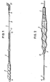
- - la Fig. 1 est une vue de la sonde gynécologique selon l'invention, en position étanche, lors de son introduction dans la cavité vaginale ou lors de son retrait,
- - la Fig. 2 est une vue en plan montrant le détail de l'embout et de l'extrémité introductive du conduit nourrissier lorsque celle-ci est en position de traitement, notamment d'insémination.
- - la Fig. 3 est une vue de profil montrant l'alimentation d'une sonde selon l'invention.
- - Fig. 1 is a view of the gynecological probe according to the invention, in the sealed position, during its introduction into the vaginal cavity or during its removal,
- - Fig. 2 is a plan view showing the detail of the endpiece and of the introductory end of the feeder duct when the latter is in the treatment position, in particular for insemination.
- - Fig. 3 is a side view showing the supply of a probe according to the invention.
La forme de réalisation ci-après décrite, se réfère au cas ou la substance à transférer est de la semence, l'instrument servant alors à l'insémination artificielle. Il est bien évident qu'il ne s'agit là que d'un exemple non limitatif, la sonde pouvant tout aussi bien servir à l'acheminement de produitsde traitement tels que ceux utilisés pour la lutte contre les infections ou la stérilité.The embodiment described below refers to the case where the substance to be transferred is semen, the instrument then serving for artificial insemination. It is obvious that this is only a nonlimiting example, the probe can just as easily be used for the delivery of treatment products such as those used for the fight against infections or infertility.
Comme illustré en figure 1, la sonde est essentiellement constituée d'une gaine protectrice extérieure 1, se présentant sous la forme d'un fourreau tubulaire, et d'un conduit coaxial 2, mobile en translation alternative dans ce fourreau et servant de canal nourrissier pour véhiculer et disposer à l'endroit souhaité la semence.As illustrated in FIG. 1, the probe essentially consists of an outer
Comme on le voit de-façon plus détaillée sur la figure 2, la gaine 1, qui est réalisée en un matériau semi-rigide par exemple en PVC, présente à son extrémité d'introduction un embout 3, qui peut être serti ou collé, cet embout présentant la particularité d'être réalisé sous la forme d'une vrille avec pas à gauche. Cet élément rapporté est réalisé de préférence en une matière plastique moulée chôi- sie pour sa souplesse, afin que le bec terminal 3i qui constitue la pointe de l'embout 3 puisse suivre les méandres des muqueuses de la cavité vaginale et surtout cervicale, sans blesser ou stresser l'animal. Cette gaine protectrice est d'une longueur sensiblement inférieure au conduit nourrissier coaxial 2, comme visible sur la figure 1, afin précisément que ce conduit puisse se déplacer en translation alternative dans la gaine qui sert alors de fourreau de guidage.As can be seen in more detail in FIG. 2, the
Le conduit intérieur 2 est réalisé en un matériau semi-rigide, par exemple en polypropylène, et présente la double particularité de comporter,d'une part,à son extrémité introductive, une tête d'obturation axiale, d'autre part, à son extrémité arrière, des repères permettant d'afficher la position exacte de cette tête par rapport à l'embout vrillé de la gaine.The
De façon plus détaillée l'extrémité introductive du conduit nourrissier 2 destiné à véhiculer la semence, comporte une tête sphérique d'introduction 4 qui obture axialement la section du conduit 2, celui-ci ne pouvant plus communiquer avec l'extérieur que par une ou plusieurs ouvertures radiales 5 situées en amont de la tête sphérique et sur la partie rétrécie de celle-ci qui se raccorde au diamètre nominal du conduit 2. Le positionnement des ouvertures est primordial car il permet de déposer la substance, en l'oc- curence la semence, en un point précis de la cavité vaginale, en évitant les projections, de direction aléatoire, qui se produisent généralement lors des expulsions axiales. Ce dépôt précis, grace au prolongateur que constitue le conduit télescopique 2, a l'avantage d'accroître la rentabilité de l'insémination, par gain de temps et de semence. On peut en effet réduire le nombre de spermatozoides par dose et même diminuer le volume de ces doses, (du fait de l'augmentation de la prolificité de la semence) ce qui permet de raccourcir le temps d'insémination.In more detail, the introductory end of the
La tête sphérique 4 peut être avantageusement emboîtée, collée ou sertie sur le conduit 2,mais sera de préférence dans l'alignement axial de ce conduit afin d'éviter toute aspérité ou écart de diamètre pouvant constituer une arête génératrice de blessure.The
Le conduit nourrissier 2 traverse axialement la gaine protectrice 1 ainsi que son embout vrillé 3 afin de déboucher à proximité du bec 31, par un orifice 6 dont le diamètre est légèrement inférieur la section dudit conduit coaxial 2. Lors de l'introduction et du retrait de la sonde, la tête sphérique 4 est amenée en retrait, dans la position illustrée en figure 1, de manière à ce qu'elle obture, avec étanchéité, l'orifice 6 de l'embout vrillé, mettant ainsi à l'abri de tout contact et surtout de toute contamination,la semence contenue dans le conduit 2, puisque les seules ouvertures 5, qui communiquent avec le canal interne de ce conduit, sont masquées par cet embout vrillé. On notera à ce sujet que le diamètre de la tête introductive 4 est légèrement supérieur à celui de l'orifice 6 afin d'obtenir une bonne étanchéité, l'élasticité de la matière constituant cet embout permettant néanmoins, une dilatation radiale de cet orifice 6 pour laisser passer ladite tête 4 lorsque l'on veut extraire le conduit 2 de la gaine. En outre, la différence de diamètre entre l'orifice 6 et la section du conduit 2 entraine un effet de pincement qui freine ledit conduit et assure son immobilisation vis à vis de l'embout.The
Les positions rétractée ou en saillie (figures 1 et 2) de la tête sphérique 4 supposent que l'on puisse contrôler son positionnement par rapport à l'embout vrillé, lorsque la sonde est introduite dans la cavité vaginale de l'animal. Pour ce faire, le conduit 2 comporte un premier repère 7, imprimé sur le conduit 2, et positionné de telle sorte que lorsque celui-ci est au droit de l'extrémité frontale arrière 11 de la gaine 1, la tête sphérique 4 est en position d'obturation dans l'embout 3. Le second repère 8 permet d'afficher la position en saillie de la tête d'expulsion 4 dans la cavité utérine, lorsque ce dit repère 8 est à son tour au droit de la face frontale arrière 11 de la gaine. On peut prévoir un troisième repère 9 correspondant à une profondeur d'introduction plus grande du conduit, le pas prévu entre ces différents repères échelonnés sur l'extrémité arrière du conduit 2 correspondant aux différentes profondeurs d'introduction, le repère arrière permettant de déposer la substance le plus loin possible du col de l'utérus afin de permettre une insémination dans les conditions optimales.The retracted or protruding positions (Figures 1 and 2) of the
L'extrémité 21 du conduit 2 est prolongée par un raccord souple 10, connecté à une réserve de semence ou à une seringue classique destinée à l'expulsion de ladite semence au travers du conduit 2, ce raccord étant souple de manière à pouvoir être replié vers le haut pour être accouplé à une réserve située dans un plan vertical et fonctionnant par pression .The
La mise en place et l'utilisation de cette sonde s'opèrent de la façon suivante :
- L'opérateur amène le conduit nourrissier 2 dans la position illustrée en figure 1 de manière à ce que la tête sphérique 4 obture l'orifice E de l'embout vrillé 3 mettant ainsi la semence à l'abri de toute contamination . A ce stade, on introduit la sonde dans la cavité vaginale jusqu'à ce que l'embout 3 rencontre le cervix. Parvenu à ce niveau, l'opérateur fera tourner la sonde sur elle-même dans le sens senestro- sum de manière à ce que l'embout se visse dans les anneaux du cervix et assure ainsi une immobilisation parfaite de la gaine dans le sens axial. Il est à noter que durant la traversée des muqueuses vaginales, la sonde est totalement obturée de sorte que tous contacts sont évités entre ladite semence et les germes microbiens qui jalonnent cette cavité. Ainsi, le matériel reste propre et stérilisé, le
conduit 2 étant totalement protégé durant la progression de la sonde dans l'animal, ce qui permet d'obtenir une bonne hygiène et une excellente protection sanitaire puisque la sonde n'est jamais polluée.
- The operator brings the
feeder duct 2 into the position illustrated in FIG. 1 so that thespherical head 4 closes the orifice E of thetwisted end piece 3 thus protecting the seed from any contamination. At this stage, the probe is introduced into the vaginal cavity until thetip 3 meets the cervix. Once at this level, the operator will rotate the probe in itself in the senestro-sum direction so that the tip is screwed into the cervix rings and thus ensures perfect immobilization of the sheath in the axial direction . It should be noted that during the crossing of the vaginal mucosa, the probe is completely closed so that all contact is avoided between said seed and the microbial germs which line this cavity. Thus, the equipment remains clean and sterilized, theconduit 2 being completely protected during the progression of the probe in the animal, which makes it possible to obtain good hygiene and excellent sanitary protection since the probe is never polluted.
Lorsque l'embout vrillé 3 est correctement immobilisé dans le cervix, l'opérateur procède alors au dégagement du conduit nourrissier 2 en le déplaçant axialement par rapport à la gaine immobile, de manière à ce que la tête sphérique 4 fasse saillie par rapport au bec 31 de cet embout comme illustré en figure 2, la profondeur d'introduction du conduit étant définie par les repères 8 et 9 figurant sur l'extrémité arrière dudit conduit 2. Cette tête sphérique 4 sera amenée le plus loin possible dans la cavité utérine de manière à ce que l'expulsion de la semence ait lieu dans les cornes utérines afin que le pourcentage de réussite de fécondation soit maximum. Il est souhaitable,par exemple,que la longueur du conduit nourrissier 2, qui fait saillie par rapport à l'embout vrillé 3, soit de l'ordre de 20 à 40 cm, selon les espèces choisies.When the
Lorsque la tête d'expulsion de la semence est correctement positionnée (cette position étant donnée par les repères visuels 8 ou 9) l'opérateur procède alors à l'éjection de la semence contenue dans la réserve (non représentée), reliée au conduit coaxial 2 par le raccord souple 10. On peut utilement avoir recours à une seringue classique contenant de 30 à 100 cm3 de semence et dont la pression suffit à expulser l'intégralité de cette semence.When the seed expulsion head is correctly positioned (this position being given by the visual references 8 or 9) the operator then ejects the semen contained in the reserve (not shown), connected to the
Selon une variante de l'invention, le conduit nourricier coaxial 2 est raccordé en vue de son alimentation à une pochette 11 de réserve de semence présentant la particularité d'être souple et déformable et de pouvoir se fixer par simple emmanchement ou vissage dans l'extrémité arrière dudit conduit 2. A cet égard,la pochette est formée de deux flans de P.V.C. de type alimentaire, thermosoudés,définissant une enveloppe plate dont la base est pourvue d'un embout de raccordement souple 12 susceptible d'être accouplé, comme indiqué précédemment, à l'extrémité arrière du conduit nourricier 2 soit par emmanchement à force à l'aide d'un nez conique 13 soit par vissage. L'embout de raccordement 12 est souple de manière à ce que la pochette 11 puisse être amenée en position verticale et former ainsi un angle de 90° par rapport à l'axe général longitudinal de la sonde pendant son introduction dans la cavité vaginale de l'animal. Ce pliage à 90* a pour effet de pincer l'embout 12 et ainsi de l'obturer, évitant ainsi que la semence contenue dans la pochette puisse se déverser dans la sonde pendant son introduction.According to a variant of the invention, the
La pochette est, avant son remplissage, plate et par conséquent exempte d'air. L'embout souple 12 est compatible avec le goulot des flacons de produit dilueur pour pouvoir être adapté à ce goulot de sorte que le remplissage de la pochette 11 se fasse directement par accouplement de l'embout 12 audit goulot. Ainsi le transfert de la semence diluée, fralche ou décongelée, se fait en milieu anaérobie, évitant toute contamination de la semence. Les parois de la pochette 11 étant déformables,la semence trouve elle-même sa place dans la pochette par dilatation vers l'extérieur des deux parois. La pochette, qui est destinée à recevoir par exemple 100 ml de semence diluée, ne se déforme que légèrement de sorte que la réserve conserve une forme générale relativement mince ce qui favorise la congélation et la décongélation de la semence. En effet, la pochette, polyvalente, sert à la fois de conteneur de réserve pour la congélation et la décongélation de la semence et de poire d'expulsion de la semence diluée dans le corps de la sonde après introduction du dilueur et accouplement de la sonde. Cette pochette,de par sa forme et surtout en raison de l'absence d'air,permet une expulsion totale de la semence et un bon contrôle manuel de son expulsion.The bag is, before filling, flat and therefore free of air. The
D'ailleurs, la quantité de semence expulsée est repérable et vérifiable grâce à des graduations 14 imprimées sur la pochette au cours de sa fabrication, permettant ainsi de contrôler l'expulsion partielle ou totale de la semence.Moreover, the quantity of semen expelled is identifiable and verifiable by means of graduations 14 printed on the pouch during its manufacture, thus making it possible to control the partial or total expulsion of the semen.
Lorsque l'opération d'insémination proprement dite est terminée,l'opérateur procède, avant extraction de la sonde, au retrait du conduit coaxial 2 de manière à l'amener en position d'obturation, telle qu'illustrée en figure 1, la tête sphérique 4 venant alors à nouveau masquer l'orifice 6 de l'embout vrillé 3. Le retrait du conduit 2 a pour effet d'éviter tout reflux de la semence après insémination, cette position d'obturation étant définie par le repère 7 visible sur le conduit coaxial 2. Ce n'est que lorsque la sonde est de nouveau hermétique'que l'on procède, après quelques minutes, à son retrait, en entraînant en rotation la gaine 1 dans le sens dextrorsum afin de dégager l'embout vrillé 3 des anneaux du cervix. Il suffit ensuite de procéder à un déplacement axial vers l'arrière de la sonde pour obtenir son retrait total. En définitive, l'invention trouve son originalité dans la combinaison d'une gaine semi-rigide à embout vrillé pouvant être immobilisée par une rotation s'apparentant à un vissage, cette gaine coopérant avec un conduit nourrissier également semi-rigide mais dont l'extrémité introductive est obturée par une tête sphérique pouvant alternativement soit masquer l'entrée de la sonde, soit la découvrir, la position de cette tête étant définie par des repères visibles sur le conduit coaxial 2. Cette conception permet ainsi d'obtenir une protection sanitaire totale de la semence durant l'introduction de la sonde, tout en évitant son reflux après insémination, grace à la capacité de ce matériel de se refermer après expulsion.When the actual insemination operation is complete, the operator proceeds, before extraction of the probe, to withdraw the
Les exemples qui viennent d'être décrits ne sont pas, comme indiqué précédemment, limitatifs,et c'est ainsi que l'instrument pourra, tel quel, être utilisé, indifféremment pour l'insémination ou le traitement vétérinaire des animaux. Le conduit télescopique 2 convient en effet au dépôt de produits ou substancesmédicamenteux pour le soin des infections ou anomalies tenant notamment à la stérilité.The examples which have just been described are not, as indicated above, limiting, and this is how the instrument can, as it is, be used, indifferently for insemination or veterinary treatment of animals. The
En outre, on pourra,sans sortir du cadre de l'invention,substituer à l'embout vrillé, en plastique ou en caoutchouc, un embout, par exemple en mousse, susceptible de se déformer pour épouser avec étanchéité les anneaux du cervix de l'animal, la tête sphérique 4 étant dans cette hypothèse d'un diamètre légèrement supérieur à celui de la tête utilisée avec l'embout plastique.In addition, it is possible, without departing from the scope of the invention, to replace the twisted end piece, made of plastic or rubber, with an end piece, for example made of foam, capable of deforming in order to hug the rings of the cervix of the animal, the
Enfin la gaine sera de préférence réalisée sous la forme d'un tube relativement épais (plusieurs dixièmes de millimètres) afin de s'opposer aux chocs thermiques, la semence porçine étant particulièrement sensible aux variations de température. Sa couleur opaque servira, quand à elle, à protéger les cellules fragiles de la nocivité des rayons tels que les ultra-violets.Finally, the sheath will preferably be produced in the form of a relatively thick tube (several tenths of a millimeter) in order to oppose thermal shocks, the porous seed being particularly sensitive to temperature variations. Its opaque color will serve to protect fragile cells from the harmful effects of rays such as ultraviolet rays.
Claims (16)
Applications Claiming Priority (2)
| Application Number | Priority Date | Filing Date | Title |
|---|---|---|---|
| FR8419723 | 1984-12-21 | ||
| FR8419723A FR2575063B1 (en) | 1984-12-21 | 1984-12-21 | GYNECOLOGICAL PROBE FOR ARTIFICIAL INSEMINATION, ESPECIALLY FOR SWINE |
Publications (2)
| Publication Number | Publication Date |
|---|---|
| EP0189702A1 true EP0189702A1 (en) | 1986-08-06 |
| EP0189702B1 EP0189702B1 (en) | 1989-11-02 |
Family
ID=9310925
Family Applications (1)
| Application Number | Title | Priority Date | Filing Date |
|---|---|---|---|
| EP19850402582 Expired EP0189702B1 (en) | 1984-12-21 | 1985-12-20 | Gynecological instrument, particularly for the artificial insemination or veterinary treatment of animals such a piglets |
Country Status (3)
| Country | Link |
|---|---|
| EP (1) | EP0189702B1 (en) |
| DE (1) | DE3573982D1 (en) |
| FR (1) | FR2575063B1 (en) |
Cited By (28)
| Publication number | Priority date | Publication date | Assignee | Title |
|---|---|---|---|---|
| FR2706123A1 (en) * | 1993-06-08 | 1994-12-16 | Gestion Engineering Et | Sampling-swab holder probe for medical and veterinary use |
| FR2706124A1 (en) * | 1993-06-08 | 1994-12-16 | Gestion Engineering Et | Probe for artificial insemination and vaginal and uterine treatment and sampling |
| FR2720929A1 (en) * | 1994-06-09 | 1995-12-15 | Gestion Engineering Et | Apparatus for gravity assisted artificial insemination |
| EP0861637A1 (en) * | 1997-02-26 | 1998-09-02 | Minitüb Abfüll- und Labortechnik GmbH & Co. KG | Artificial insemination catheter, in particular for pigs |
| WO2000054700A1 (en) * | 1999-03-17 | 2000-09-21 | Santiago Martin Rillo | Cannula for artificial insemination of hogs |
| FR2803189A1 (en) | 1999-12-31 | 2001-07-06 | Imv Technologies | DEVICE FOR ARTIFICIAL INSEMINATION, IN PARTICULAR FOR SWINE |
| WO2001049205A1 (en) * | 2000-01-03 | 2001-07-12 | Iberica De Reproduccion Asistida, S.L. | Artificial insemination device for pigs |
| WO2001085057A1 (en) * | 2000-05-05 | 2001-11-15 | Richard Andrew Openshaw | Metering device for use in artificial insemination of an animal |
| WO2002035982A2 (en) * | 2000-11-03 | 2002-05-10 | Continental Plastic Corp. | Device for trans-cervical artificial insemination and embryo transfer |
| EP1066802A3 (en) * | 1999-07-09 | 2002-06-12 | Livestock Improvement Association of Japan Inc. | Injector of sperm or of a fertilized ovum into a domestic animal and method of operation thereof |
| ES2171128A1 (en) * | 2000-09-29 | 2002-08-16 | Iberica De Reproduccion Asisti | Artificial insemination device for pigs, comprises cannula with plug at front end and side holes close to plug in narrow region of cannula |
| EP1249212A1 (en) * | 2001-04-11 | 2002-10-16 | IMV Technologies | Bag for packing animal semen and for treatment of the uterus |
| ES2188351A1 (en) * | 2001-02-23 | 2003-06-16 | Magapor S L | System to manufacture catheters for artificial insemination and the catheters obtained. |
| FR2835422A1 (en) | 2002-02-05 | 2003-08-08 | Imv Technologies | FITTING FOR A GYNECOLOGICAL INSTRUMENT FOR VETERINARY USE |
| US7175590B2 (en) | 2001-11-01 | 2007-02-13 | Continental Plastic Corp. | Apparatus for trans-cervical artificial insemination and embryo transfer |
| EP2140834A1 (en) | 2008-06-30 | 2010-01-06 | IMV Technologies | Intra-uterine transfer apparatus using the natural vaginal-uterine route |
| US7713687B2 (en) | 2000-11-29 | 2010-05-11 | Xy, Inc. | System to separate frozen-thawed spermatozoa into x-chromosome bearing and y-chromosome bearing populations |
| US7723116B2 (en) | 2003-05-15 | 2010-05-25 | Xy, Inc. | Apparatus, methods and processes for sorting particles and for providing sex-sorted animal sperm |
| US7772005B1 (en) | 1998-07-30 | 2010-08-10 | Xy, Llc | Method of establishing an equine artificial insemination sample |
| US7820425B2 (en) | 1999-11-24 | 2010-10-26 | Xy, Llc | Method of cryopreserving selected sperm cells |
| US7855078B2 (en) | 2002-08-15 | 2010-12-21 | Xy, Llc | High resolution flow cytometer |
| US7929137B2 (en) | 1997-01-31 | 2011-04-19 | Xy, Llc | Optical apparatus |
| US8137967B2 (en) | 2000-11-29 | 2012-03-20 | Xy, Llc | In-vitro fertilization systems with spermatozoa separated into X-chromosome and Y-chromosome bearing populations |
| US8486618B2 (en) | 2002-08-01 | 2013-07-16 | Xy, Llc | Heterogeneous inseminate system |
| US8497063B2 (en) | 2002-08-01 | 2013-07-30 | Xy, Llc | Sex selected equine embryo production system |
| US9145590B2 (en) | 2000-05-09 | 2015-09-29 | Xy, Llc | Methods and apparatus for high purity X-chromosome bearing and Y-chromosome bearing populations of spermatozoa |
| US9365822B2 (en) | 1997-12-31 | 2016-06-14 | Xy, Llc | System and method for sorting cells |
| US11230695B2 (en) | 2002-09-13 | 2022-01-25 | Xy, Llc | Sperm cell processing and preservation systems |
Families Citing this family (3)
| Publication number | Priority date | Publication date | Assignee | Title |
|---|---|---|---|---|
| FR2667504B1 (en) * | 1990-10-09 | 1992-11-27 | Cassou Robert | DOSE BAG FOR ANIMAL SEED FOR ARTIFICIAL INSEMINATION. |
| FR2668054B1 (en) * | 1990-10-19 | 1992-12-11 | Cooperative Bretonne Insem Art | PROBE NOZZLE FOR ARTIFICIAL INSEMINATION OF ANIMALS SUCH AS SOWS. |
| US6511415B1 (en) * | 2000-11-03 | 2003-01-28 | Continental Plastic Corp. | Device for trans-cervical artificial insemination and embryo transfer |
Citations (7)
| Publication number | Priority date | Publication date | Assignee | Title |
|---|---|---|---|---|
| BE497676A (en) * | 1949-08-24 | |||
| US4049033A (en) * | 1974-11-21 | 1977-09-20 | Baxter Travenol Laboratories, Inc. | Molded collapsible solution container |
| DE2709302A1 (en) * | 1976-11-24 | 1978-09-07 | Zeppelin Dieter Von | Catheter with axially movable sleeve forming seal - has sealing bead formed by array of arcuate strips forming part of sleeve or by resilient foamed plastics ring |
| FR2450102A1 (en) * | 1979-03-02 | 1980-09-26 | Cassou Robert | Instrument for artificial insemination of pigs - has hollow tube sliding in cylindrical body with one end in communication with reservoir of semen and other entering animal |
| EP0071538A1 (en) * | 1981-07-31 | 1983-02-09 | Bertrand Cassou | Apparatus for transferring animal reproduction elements, embryos or the like |
| FR2513111A1 (en) * | 1981-09-23 | 1983-03-25 | Girault Francois | Endoscopically installed oesophageal prosthesis - has flexible tube with covered funnel having coaxial hole of dia. close to that of tube |
| US4410026A (en) * | 1981-07-13 | 1983-10-18 | Baxter Travenol Laboratories, Inc. | Port block assembly for interconnecting a fluid container with a fluid conduit |
Family Cites Families (3)
| Publication number | Priority date | Publication date | Assignee | Title |
|---|---|---|---|---|
| CH585550A5 (en) * | 1974-01-18 | 1977-03-15 | Abbott Lab | Drug supporting anchor - having spiral configuration for insertion into body cavities |
| FR2450103A1 (en) * | 1979-03-02 | 1980-09-26 | Cassou Robert | Instrument for artificial insemination of pigs - has hollow tube sliding in cylindrical body with inflatable balloon containing it around it and in fluid communication with it |
| FR2556596B1 (en) * | 1983-12-16 | 1986-12-05 | Cassou Robert | INSTRUMENTS FOR GYNECOLOGICAL ACTION, ESPECIALLY TRANSFER OF EMBRYOS |
-
1984
- 1984-12-21 FR FR8419723A patent/FR2575063B1/en not_active Expired
-
1985
- 1985-12-20 EP EP19850402582 patent/EP0189702B1/en not_active Expired
- 1985-12-20 DE DE8585402582T patent/DE3573982D1/en not_active Expired
Patent Citations (7)
| Publication number | Priority date | Publication date | Assignee | Title |
|---|---|---|---|---|
| BE497676A (en) * | 1949-08-24 | |||
| US4049033A (en) * | 1974-11-21 | 1977-09-20 | Baxter Travenol Laboratories, Inc. | Molded collapsible solution container |
| DE2709302A1 (en) * | 1976-11-24 | 1978-09-07 | Zeppelin Dieter Von | Catheter with axially movable sleeve forming seal - has sealing bead formed by array of arcuate strips forming part of sleeve or by resilient foamed plastics ring |
| FR2450102A1 (en) * | 1979-03-02 | 1980-09-26 | Cassou Robert | Instrument for artificial insemination of pigs - has hollow tube sliding in cylindrical body with one end in communication with reservoir of semen and other entering animal |
| US4410026A (en) * | 1981-07-13 | 1983-10-18 | Baxter Travenol Laboratories, Inc. | Port block assembly for interconnecting a fluid container with a fluid conduit |
| EP0071538A1 (en) * | 1981-07-31 | 1983-02-09 | Bertrand Cassou | Apparatus for transferring animal reproduction elements, embryos or the like |
| FR2513111A1 (en) * | 1981-09-23 | 1983-03-25 | Girault Francois | Endoscopically installed oesophageal prosthesis - has flexible tube with covered funnel having coaxial hole of dia. close to that of tube |
Cited By (40)
| Publication number | Priority date | Publication date | Assignee | Title |
|---|---|---|---|---|
| FR2706124A1 (en) * | 1993-06-08 | 1994-12-16 | Gestion Engineering Et | Probe for artificial insemination and vaginal and uterine treatment and sampling |
| FR2706123A1 (en) * | 1993-06-08 | 1994-12-16 | Gestion Engineering Et | Sampling-swab holder probe for medical and veterinary use |
| FR2720929A1 (en) * | 1994-06-09 | 1995-12-15 | Gestion Engineering Et | Apparatus for gravity assisted artificial insemination |
| US7929137B2 (en) | 1997-01-31 | 2011-04-19 | Xy, Llc | Optical apparatus |
| EP0861637A1 (en) * | 1997-02-26 | 1998-09-02 | Minitüb Abfüll- und Labortechnik GmbH & Co. KG | Artificial insemination catheter, in particular for pigs |
| US9422523B2 (en) | 1997-12-31 | 2016-08-23 | Xy, Llc | System and method for sorting cells |
| US9365822B2 (en) | 1997-12-31 | 2016-06-14 | Xy, Llc | System and method for sorting cells |
| US7772005B1 (en) | 1998-07-30 | 2010-08-10 | Xy, Llc | Method of establishing an equine artificial insemination sample |
| WO2000054700A1 (en) * | 1999-03-17 | 2000-09-21 | Santiago Martin Rillo | Cannula for artificial insemination of hogs |
| EP1066802A3 (en) * | 1999-07-09 | 2002-06-12 | Livestock Improvement Association of Japan Inc. | Injector of sperm or of a fertilized ovum into a domestic animal and method of operation thereof |
| US7820425B2 (en) | 1999-11-24 | 2010-10-26 | Xy, Llc | Method of cryopreserving selected sperm cells |
| WO2001049206A1 (en) * | 1999-12-31 | 2001-07-12 | Imv Technologies | Artificial insemination device, in particular for pigs |
| FR2803189A1 (en) | 1999-12-31 | 2001-07-06 | Imv Technologies | DEVICE FOR ARTIFICIAL INSEMINATION, IN PARTICULAR FOR SWINE |
| WO2001049205A1 (en) * | 2000-01-03 | 2001-07-12 | Iberica De Reproduccion Asistida, S.L. | Artificial insemination device for pigs |
| WO2001085057A1 (en) * | 2000-05-05 | 2001-11-15 | Richard Andrew Openshaw | Metering device for use in artificial insemination of an animal |
| US9145590B2 (en) | 2000-05-09 | 2015-09-29 | Xy, Llc | Methods and apparatus for high purity X-chromosome bearing and Y-chromosome bearing populations of spermatozoa |
| US10208345B2 (en) | 2000-05-09 | 2019-02-19 | Xy, Llc | Method for producing high purity X-chromosome bearing and Y-chromosome bearing populations of spermatozoa |
| ES2171128A1 (en) * | 2000-09-29 | 2002-08-16 | Iberica De Reproduccion Asisti | Artificial insemination device for pigs, comprises cannula with plug at front end and side holes close to plug in narrow region of cannula |
| WO2002035982A3 (en) * | 2000-11-03 | 2003-03-06 | Continental Plastic Corp | Device for trans-cervical artificial insemination and embryo transfer |
| WO2002035982A2 (en) * | 2000-11-03 | 2002-05-10 | Continental Plastic Corp. | Device for trans-cervical artificial insemination and embryo transfer |
| US7713687B2 (en) | 2000-11-29 | 2010-05-11 | Xy, Inc. | System to separate frozen-thawed spermatozoa into x-chromosome bearing and y-chromosome bearing populations |
| US7771921B2 (en) | 2000-11-29 | 2010-08-10 | Xy, Llc | Separation systems of frozen-thawed spermatozoa into X-chromosome bearing and Y-chromosome bearing populations |
| US9879221B2 (en) | 2000-11-29 | 2018-01-30 | Xy, Llc | Method of in-vitro fertilization with spermatozoa separated into X-chromosome and Y-chromosome bearing populations |
| US8652769B2 (en) | 2000-11-29 | 2014-02-18 | Xy, Llc | Methods for separating frozen-thawed spermatozoa into X-chromosome bearing and Y-chromosome bearing populations |
| US8137967B2 (en) | 2000-11-29 | 2012-03-20 | Xy, Llc | In-vitro fertilization systems with spermatozoa separated into X-chromosome and Y-chromosome bearing populations |
| ES2188351A1 (en) * | 2001-02-23 | 2003-06-16 | Magapor S L | System to manufacture catheters for artificial insemination and the catheters obtained. |
| EP1249212A1 (en) * | 2001-04-11 | 2002-10-16 | IMV Technologies | Bag for packing animal semen and for treatment of the uterus |
| FR2823435A1 (en) * | 2001-04-11 | 2002-10-18 | Imv Technologies | BAG FOR PACKAGING ANIMAL SEED AND UTERINE TREATMENT |
| US6964656B2 (en) | 2001-04-11 | 2005-11-15 | Imv Technologies | Sachet for packaging animal semen and for uterine treatment |
| KR100501112B1 (en) * | 2001-04-11 | 2005-07-18 | 이엠므베 떼끄놀로지 | A sachet for packaging animal semen and for uterine treatment |
| US7175590B2 (en) | 2001-11-01 | 2007-02-13 | Continental Plastic Corp. | Apparatus for trans-cervical artificial insemination and embryo transfer |
| WO2003065925A1 (en) | 2002-02-05 | 2003-08-14 | Imv Technologies | Connection for gynecological instrument |
| FR2835422A1 (en) | 2002-02-05 | 2003-08-08 | Imv Technologies | FITTING FOR A GYNECOLOGICAL INSTRUMENT FOR VETERINARY USE |
| US8497063B2 (en) | 2002-08-01 | 2013-07-30 | Xy, Llc | Sex selected equine embryo production system |
| US8486618B2 (en) | 2002-08-01 | 2013-07-16 | Xy, Llc | Heterogeneous inseminate system |
| US7855078B2 (en) | 2002-08-15 | 2010-12-21 | Xy, Llc | High resolution flow cytometer |
| US11230695B2 (en) | 2002-09-13 | 2022-01-25 | Xy, Llc | Sperm cell processing and preservation systems |
| US11261424B2 (en) | 2002-09-13 | 2022-03-01 | Xy, Llc | Sperm cell processing systems |
| US7723116B2 (en) | 2003-05-15 | 2010-05-25 | Xy, Inc. | Apparatus, methods and processes for sorting particles and for providing sex-sorted animal sperm |
| EP2140834A1 (en) | 2008-06-30 | 2010-01-06 | IMV Technologies | Intra-uterine transfer apparatus using the natural vaginal-uterine route |
Also Published As
| Publication number | Publication date |
|---|---|
| FR2575063B1 (en) | 1988-07-01 |
| EP0189702B1 (en) | 1989-11-02 |
| FR2575063A1 (en) | 1986-06-27 |
| DE3573982D1 (en) | 1989-12-07 |
Similar Documents
| Publication | Publication Date | Title |
|---|---|---|
| EP0189702B1 (en) | Gynecological instrument, particularly for the artificial insemination or veterinary treatment of animals such a piglets | |
| EP0278823B1 (en) | Instrument for artificial insemination, embryo transfer, or sampling of folicular fluids | |
| EP0162770B1 (en) | Artificial insemination device, in particular for carnivores | |
| EP0605406B1 (en) | Insemination probe | |
| FR2900327A1 (en) | ARTIFICIAL INSEMINATION GUN PIPE, METHOD OF MANUFACTURING SAME, AND ARTIFICIAL INSEMINATION METHOD | |
| FR2539302A1 (en) | SYRINGE FOR MEDICAL USE | |
| FR2574656A1 (en) | Gynaecological probe in particular for injecting semen or embryos into the cavity of animals, such as mares | |
| FR2647668A1 (en) | Transfer pipette for embryos | |
| EP1166720B1 (en) | Echogenic or radiopaque device for sampling or tranferring into the genital organs | |
| EP2437681B1 (en) | Probe for artificial insemination, in particular for pigs | |
| FR2524324A1 (en) | CATHETER FOR INTRODUCING IN THE UTERUS A FECONDE IN VITRO EGG AND METHOD OF USE | |
| EP1249212A1 (en) | Bag for packing animal semen and for treatment of the uterus | |
| FR3021861A1 (en) | IMPROVED ATRAUMATIC TRANSFER DEVICE FOR REPRODUCTIVE, THERAPEUTIC OR DIAGNOSTIC MATERIAL OR SUBSTANCE IN FEMALE MAMMALS | |
| WO2016193630A1 (en) | Straw for keeping a predetermined dose of liquid-based substance, and injection device and method implementing same | |
| FR2605211A1 (en) | Insemination applicator | |
| FR2607012A1 (en) | CATHETER ASSEMBLY FOR INTRAVENOUS ADMINISTRATION | |
| FR2915874A1 (en) | Artificial insemination device for livestock e.g. sow, has probe inserted in vagina of animal, and check valve that is constituted by case with elastic and flexible wall surrounded around wall at level of inlet opening | |
| EP2140834B1 (en) | Intra-uterine transfer apparatus using the natural vaginal-uterine route | |
| FR2546399A1 (en) | APPLICATOR FOR THE PLACEMENT OF AN OBJECT IN THE VAGINA OF A FEMALE ANIMAL | |
| EP0066488B1 (en) | Animal single-use dosage of semen for artificial insemination of poultry, e.g. hens | |
| FR2706124A1 (en) | Probe for artificial insemination and vaginal and uterine treatment and sampling | |
| FR2889051A1 (en) | Bred animal`s e.g. sow, artificial insemination device, has reservoir connected to catheter and including envelope utilized outside reproductive system and valve permitting to fill envelope with semen under pressure | |
| FR2977145A1 (en) | Intra-uterine probe for inseminating porcine, has semen storage unit including semen storage area filled with semen, where semen is moved into secondary cylindrical body by aspiration and under effect of contraction of storage area | |
| EP4183368A1 (en) | Device for artificial insemination of farm animals and protective sleeve for such a device | |
| FR2835422A1 (en) | FITTING FOR A GYNECOLOGICAL INSTRUMENT FOR VETERINARY USE |
Legal Events
| Date | Code | Title | Description |
|---|---|---|---|
| PUAI | Public reference made under article 153(3) epc to a published international application that has entered the european phase |
Free format text: ORIGINAL CODE: 0009012 |
|
| AK | Designated contracting states |
Kind code of ref document: A1 Designated state(s): DE FR IT NL |
|
| 17P | Request for examination filed |
Effective date: 19861204 |
|
| 17Q | First examination report despatched |
Effective date: 19880323 |
|
| GRAA | (expected) grant |
Free format text: ORIGINAL CODE: 0009210 |
|
| AK | Designated contracting states |
Kind code of ref document: B1 Designated state(s): DE FR IT NL |
|
| ITF | It: translation for a ep patent filed |
Owner name: JACOBACCI & PERANI S.P.A. |
|
| REF | Corresponds to: |
Ref document number: 3573982 Country of ref document: DE Date of ref document: 19891207 |
|
| PLBE | No opposition filed within time limit |
Free format text: ORIGINAL CODE: 0009261 |
|
| STAA | Information on the status of an ep patent application or granted ep patent |
Free format text: STATUS: NO OPPOSITION FILED WITHIN TIME LIMIT |
|
| 26N | No opposition filed | ||
| ITTA | It: last paid annual fee | ||
| PGFP | Annual fee paid to national office [announced via postgrant information from national office to epo] |
Ref country code: DE Payment date: 19951227 Year of fee payment: 11 |
|
| PGFP | Annual fee paid to national office [announced via postgrant information from national office to epo] |
Ref country code: NL Payment date: 19951230 Year of fee payment: 11 |
|
| PG25 | Lapsed in a contracting state [announced via postgrant information from national office to epo] |
Ref country code: NL Effective date: 19970701 |
|
| NLV4 | Nl: lapsed or anulled due to non-payment of the annual fee |
Effective date: 19970701 |
|
| PG25 | Lapsed in a contracting state [announced via postgrant information from national office to epo] |
Ref country code: DE Effective date: 19970902 |
|
| PGFP | Annual fee paid to national office [announced via postgrant information from national office to epo] |
Ref country code: FR Payment date: 20031027 Year of fee payment: 19 |
|
| PG25 | Lapsed in a contracting state [announced via postgrant information from national office to epo] |
Ref country code: FR Free format text: LAPSE BECAUSE OF NON-PAYMENT OF DUE FEES Effective date: 20050831 |
|
| REG | Reference to a national code |
Ref country code: FR Ref legal event code: ST |