EP0192840B1 - Appliance for fixing fractures of the femur - Google Patents
Appliance for fixing fractures of the femur Download PDFInfo
- Publication number
- EP0192840B1 EP0192840B1 EP85115748A EP85115748A EP0192840B1 EP 0192840 B1 EP0192840 B1 EP 0192840B1 EP 85115748 A EP85115748 A EP 85115748A EP 85115748 A EP85115748 A EP 85115748A EP 0192840 B1 EP0192840 B1 EP 0192840B1
- Authority
- EP
- European Patent Office
- Prior art keywords
- nail
- intramedullary nail
- cross
- appliance
- slit
- Prior art date
- Legal status (The legal status is an assumption and is not a legal conclusion. Google has not performed a legal analysis and makes no representation as to the accuracy of the status listed.)
- Expired
Links
- 210000000689 upper leg Anatomy 0.000 title claims description 84
- 210000002436 femur neck Anatomy 0.000 claims description 20
- 238000002513 implantation Methods 0.000 claims description 12
- 238000010276 construction Methods 0.000 claims description 7
- 210000000501 femur body Anatomy 0.000 claims description 4
- 206010017076 Fracture Diseases 0.000 description 25
- 208000010392 Bone Fractures Diseases 0.000 description 13
- 239000012634 fragment Substances 0.000 description 11
- 210000000527 greater trochanter Anatomy 0.000 description 10
- 210000001699 lower leg Anatomy 0.000 description 8
- 206010020100 Hip fracture Diseases 0.000 description 7
- 230000035876 healing Effects 0.000 description 4
- 208000015181 infectious disease Diseases 0.000 description 4
- 238000009940 knitting Methods 0.000 description 4
- 230000015572 biosynthetic process Effects 0.000 description 3
- 210000002414 leg Anatomy 0.000 description 3
- 206010041899 Stab wound Diseases 0.000 description 2
- 238000005452 bending Methods 0.000 description 2
- 210000000988 bone and bone Anatomy 0.000 description 2
- 210000003141 lower extremity Anatomy 0.000 description 2
- 239000002184 metal Substances 0.000 description 2
- 238000000554 physical therapy Methods 0.000 description 2
- 230000007480 spreading Effects 0.000 description 2
- 229910001220 stainless steel Inorganic materials 0.000 description 2
- 239000010935 stainless steel Substances 0.000 description 2
- CPKVUHPKYQGHMW-UHFFFAOYSA-N 1-ethenylpyrrolidin-2-one;molecular iodine Chemical compound II.C=CN1CCCC1=O CPKVUHPKYQGHMW-UHFFFAOYSA-N 0.000 description 1
- 208000024779 Comminuted Fractures Diseases 0.000 description 1
- 208000008924 Femoral Fractures Diseases 0.000 description 1
- 206010020649 Hyperkeratosis Diseases 0.000 description 1
- 206010052428 Wound Diseases 0.000 description 1
- 208000027418 Wounds and injury Diseases 0.000 description 1
- 229940064804 betadine Drugs 0.000 description 1
- 230000003111 delayed effect Effects 0.000 description 1
- 238000005553 drilling Methods 0.000 description 1
- 230000000694 effects Effects 0.000 description 1
- 210000000109 fascia lata Anatomy 0.000 description 1
- 230000037431 insertion Effects 0.000 description 1
- 238000003780 insertion Methods 0.000 description 1
- 230000003447 ipsilateral effect Effects 0.000 description 1
- 210000003127 knee Anatomy 0.000 description 1
- 238000002350 laparotomy Methods 0.000 description 1
- 210000002640 perineum Anatomy 0.000 description 1
- 230000009467 reduction Effects 0.000 description 1
- 230000004044 response Effects 0.000 description 1
- 230000000284 resting effect Effects 0.000 description 1
- 238000007493 shaping process Methods 0.000 description 1
- 238000004904 shortening Methods 0.000 description 1
- 210000002303 tibia Anatomy 0.000 description 1
Images

Classifications
-
- A—HUMAN NECESSITIES
- A61—MEDICAL OR VETERINARY SCIENCE; HYGIENE
- A61B—DIAGNOSIS; SURGERY; IDENTIFICATION
- A61B17/00—Surgical instruments, devices or methods, e.g. tourniquets
- A61B17/56—Surgical instruments or methods for treatment of bones or joints; Devices specially adapted therefor
- A61B17/58—Surgical instruments or methods for treatment of bones or joints; Devices specially adapted therefor for osteosynthesis, e.g. bone plates, screws, setting implements or the like
- A61B17/68—Internal fixation devices, including fasteners and spinal fixators, even if a part thereof projects from the skin
- A61B17/74—Devices for the head or neck or trochanter of the femur
- A61B17/742—Devices for the head or neck or trochanter of the femur having one or more longitudinal elements oriented along or parallel to the axis of the neck
- A61B17/744—Devices for the head or neck or trochanter of the femur having one or more longitudinal elements oriented along or parallel to the axis of the neck the longitudinal elements coupled to an intramedullary nail
-
- A—HUMAN NECESSITIES
- A61—MEDICAL OR VETERINARY SCIENCE; HYGIENE
- A61B—DIAGNOSIS; SURGERY; IDENTIFICATION
- A61B17/00—Surgical instruments, devices or methods, e.g. tourniquets
- A61B17/56—Surgical instruments or methods for treatment of bones or joints; Devices specially adapted therefor
- A61B17/58—Surgical instruments or methods for treatment of bones or joints; Devices specially adapted therefor for osteosynthesis, e.g. bone plates, screws, setting implements or the like
- A61B17/68—Internal fixation devices, including fasteners and spinal fixators, even if a part thereof projects from the skin
- A61B17/72—Intramedullary pins, nails or other devices
- A61B17/7233—Intramedullary pins, nails or other devices with special means of locking the nail to the bone
- A61B17/725—Intramedullary pins, nails or other devices with special means of locking the nail to the bone with locking pins or screws of special form
-
- A—HUMAN NECESSITIES
- A61—MEDICAL OR VETERINARY SCIENCE; HYGIENE
- A61B—DIAGNOSIS; SURGERY; IDENTIFICATION
- A61B17/00—Surgical instruments, devices or methods, e.g. tourniquets
- A61B17/56—Surgical instruments or methods for treatment of bones or joints; Devices specially adapted therefor
- A61B17/58—Surgical instruments or methods for treatment of bones or joints; Devices specially adapted therefor for osteosynthesis, e.g. bone plates, screws, setting implements or the like
- A61B17/68—Internal fixation devices, including fasteners and spinal fixators, even if a part thereof projects from the skin
- A61B17/72—Intramedullary pins, nails or other devices
- A61B17/7233—Intramedullary pins, nails or other devices with special means of locking the nail to the bone
- A61B17/7258—Intramedullary pins, nails or other devices with special means of locking the nail to the bone with laterally expanding parts, e.g. for gripping the bone
-
- A—HUMAN NECESSITIES
- A61—MEDICAL OR VETERINARY SCIENCE; HYGIENE
- A61B—DIAGNOSIS; SURGERY; IDENTIFICATION
- A61B17/00—Surgical instruments, devices or methods, e.g. tourniquets
- A61B17/56—Surgical instruments or methods for treatment of bones or joints; Devices specially adapted therefor
- A61B17/58—Surgical instruments or methods for treatment of bones or joints; Devices specially adapted therefor for osteosynthesis, e.g. bone plates, screws, setting implements or the like
- A61B17/68—Internal fixation devices, including fasteners and spinal fixators, even if a part thereof projects from the skin
- A61B17/72—Intramedullary pins, nails or other devices
- A61B17/7283—Intramedullary pins, nails or other devices with special cross-section of the nail
Definitions
- the present invention relates generally to improvements in devices for fixing skeletal fractures and, more particularly, but not by way of limitation, for fixing fractures of the femur.
- one appliance comprises a plate that can be attached to the lateral side of the femur via screws and a nail that slides in a channel member at the top of the plate for implantation in the head and neck of the femur.
- Another appliance has a nail implanted in the intramedullary canal and is used in place of the plate.
- Another such appliance comprises an intramedullary nail that is extended into the intramedullary canal and passes through a hole formed through a femoral spike or cross nail, that is extended into the head and neck of the femur.
- Yet another appliance known from US-A-3433220 comprises an intramedullary rod that is implanted in the intramedullary canal and has a hole formed through portions thereof near the upper end of the rod to receive a cross nail that is extended into the head and neck of the femur.
- a locking screw is introduced through the upper end of the intramedullary rod to engage the cross nail and fix the cross nail in position within the hole through the intramedullary rod.
- an intramedullary rod is well suited for transverse subtrochanteric fractures of the femur, it is not well adapted to fractures that occur in the intertrochanteric, neck and head portions of the femur or comminuted subtrochanteric fractures of the femur.
- the cross nail or intramedullary rod are particularly well adapted to the treatment of fractures of the femoral neck, intertrochanteric region or subtrochanteric region of the femur that occur in association with ipsilateral femoral shaft fractures.
- the present invention provides an appliance for fixing fractures of the femur, comprising: a tubular intramedullary nail for implantation in the intramedullary canal of the femur, the intramedullary nail having a longitudinally extending slit formed through the wall thereof along one side of the intramedullary nail; a cross nail for implantation in the proximal femur, the cross nail having a heel portion at one end thereof and a blade portion extending from the heel portion to the other end of the cross nail for positioning in the head and neck of the femur, wherein an aperture is formed through the blade portion of the cross nail at the juncture of said two portions of the cross nail to receive the intramedullary nail therethrough, said aperture extending through the cross nail to receive the intramedullary nail therethrough, said aperture extending through the cross nail at an angle to the blade portion substantially equal to the angle between the neck and shaft of the femur, and wherein a threaded bore is formed longitudinally through the heel portion
- the resulting secure locking of the intramedullary nail to the cross nail provides a rigid structure that supports fragments of the femur throughout the shaft, subtrochanteric and intertrochanteric portions thereof to enhance the knitting of such fragments.
- FIG. 10 shown therein and designated by the general reference numeral 10 is an appliance for fixing fractures of the femur constructed in accordance with the present invention.
- a femur 12 has been drawn in dot-dash line in Figure 1 to illustrate the position of the appliance 10 after implantation in the femur 12.
- the appliance 10 is comprised of a cross nail 14 which, when implanted in the femur 12, extends generally from the base of the greater trochanter and into the head and neck of the femur 12.
- An aperture 16 ( Figures 2 and 3) is formed through the cross nail 14 to receive an intramedullary pin or nail 18 that extends downwardly into the intramedullary canal of the femur from a position slightly medial to the tip.of the greater trochanter as illustrated in Figure 1.
- the appliance 10 is further comprised of a locking screw 20 ( Figure 4) that firmly fixes the intramedullary nail 18 within the aperture 16 of the cross nail 14 in a manner that will be discussed below.
- the cross nail 14 which is preferably machined from a bar of type 316L stainless steel, has a heel portion 22 adjacent one end 24 of the cross nail 14. As can be seen in Figure 1, the end 24 is angled to lie flush with the outer surface of the lateral cortex when the cross nail 14 is implanted in a femur to extend along the axis of the femoral neck. Extending from the heel portion 22 to the opposite end 26 of the cross nail 14, the cross nail 14 is further comprised of a blade portion 28.
- the aperture 16 is positioned in the blade portion 28 and extends through the cross nail 14 at an angle to the blade portion that is substantially equal to the angle between the neck and shaft of the femur.
- the aperture 16 will align the intramedullary nail 18 with the intramedullary canal at such times that the cross nail 14 is implanted in the femur 12 such that the blade portion 28 thereof extends generally parallel to the axis of the neck of the femur as illustrated in Figure 1.
- the aperture 16 is substantially D-shaped, the aperture 16 being defined by a flattened, internal surface 30 of the heel portion 22, the surface 30 forming the flat side of the D, and a surface 32 of the blade portion 28 that extends arcuately between the ends of the surface 30.
- a threaded bore 34 is formed longitudinally through upper portions of the heel portion 22 to intersect the end 24 of the cross nail 14 and the flattened surface 30 of the aperture 16, the axis of the bore 34 extending generally normally to the flattened surface 30 defining the aperture 16.
- the bore 34 is counterbored from the end 24 of the cross nail 14 to form a socket 35 for a purpose to be discussed below.
- a hole 36 is formed through the heel portion 22, also intersecting the end 24 of the heel portion 22 of the cross nail 14 and the flattened surface 30 defining the aperture 16, for a purpose also to be discussed below.
- the blade portion 28 of the cross nail 14 is rounded at the end 26, as shown in Figure 2, and has an upper surface 38 that slopes toward the lower side 40 from the heel portion 22 to the end 26 of the cross nail 14.
- a channel 42 is cut in the upper surface 38 from the end 26 of the cross nail 14 to the aperture 16 so that the blade portion 28 has a generally U-shaped cross section throughout its length. Portions of the blade portion 28 about the surface 32 are broadened to maintain a relatively thick wall for the blade portion 28 throughout the length thereof.
- Such construction of the cross nail 14 facilitates the implantation of the cross nail 14 in the femur 12 while contributing to a strength and rigidity of the appliance 10 that will permit the appliance 10 to support the weight of the person in which the appliance 10 is implanted.
- the construction of the intramedullary nail 18 can best be seen from Figures 1, 8 and 9.
- the intramedullary nail 18 is constructed by bending a metal strip, preferably composed of type 316L stainless steel, about the long axis of the strip so that the intramedullary nail 18 has the general form of an elongated tube as indicated in Figure 1.
- a space is left between the side edges 44 and 46 of the strip so that a slit 48 extending the length of the intramedullary nail 1.8 is formed through the wall 50 of the intramedullary nail 18 at one side 52 thereof.
- the width of the slit 48 is selected to coact with the locking screw 20 in a manner that will be discussed below.
- Portions of the wall 50 of the intramedullary nail 18 adjacent the edges 44 and 46 are bent inwardly so that the intramedullary nail 18 has a generally flattened construction, as indicated by the line 53 in Figure 9, along the side 52 of the intramedullary nail 18.
- the flattened side 52 of the intramedullary nail 18 is positioned adjacent the flattened surface 30 formed on the heel portion 22 of the cross nail 14 when the appliance 10 is assembled so that, when the intramedullary nail 18 is inserted through the aperture 16, the side 52 will co-act with the surface 30 to maintain the slit 48 in alignment with the axis of the threaded bore 34 through the heel portion 22 of the cross nail 14.
- the flattening of the side 52 is preferably effected by providing the intramedullary nail 18 with a trifoliate cross section and forming the slit 48 between two petals of such cross section.
- concavities 54 and 56 are formed in portions of the tubular wall 50 of the intramedullary nail 18 displaced from the slit 48, the concavities 54 and 56 extending substantially the length of the intramedullary nail 18.
- the trifoliate cross section of the intramedullary nail 18 permits the intramedullary nail 18 to be constructed of a relatively light gauge metal while providing the intramedullary nail 18 with a rigidity sufficient to support the weight of the human body.
- the present invention contemplates that such rigidity will be exploited in the healing of severely comminuted fractures by using the appliance 10 to maintain the femur in internal traction during the healing of the fracture.
- the femur is placed in traction by the mounting of the cross nail 14 in the upper portions of the femur 12, rigidly securing upper end portions 58 (Figure 1) of the intramedullary nail 18 to the cross nail 14 in a manner to be discussed below, and by securing lower end portions 60 of the intramedullary nail 18 to lower portions of the femur 12 in a manner shown in Figure 1.
- one or more holes 62 are formed through the wall 50 in the lower end portion 60 of the intramedullary nail 18, such holes 62 being positioned opposite the side 52 of the intramedullary nail 18 through which the slit 48 is formed.
- the diameters of the holes 62 are made slightly larger than the width of the slit 48 and arcuate cuts 64 are formed in the edges 44 and 46 defining the slit 48 to align with the holes 62.
- the cuts 64 in the edges 44 and 46 are formed on a radius of curvature equal to the radii of the holes 62 to define, with the holes 62, one or more circular passages extending through the intramedullary nail 18 from the side 52 of the intramedullary nail 18 to the opposite side thereof.
- screws 66 can be passed through the passages formed by the holes 62 and cuts 64 to screw into lower portions of the femur 12 when the appliance 10 is implanted in the femur 12.
- a rectangular hole 67 is formed through the wall of the nail 18 near the upper end thereof to facilitate removal of the appliance 10 from the femur 12 after healing of the fracture has occurred.
- the locking screw 20 has a shank 68 that is provided with external threads to mate with the threads in the bore 34 formed through the heel portion 22 of the cross nail 14 so that the locking screw 20 can be screwed into the hole 34 of the cross nail 14.
- the locking screw 20 has an enlarged head 70 at one end thereof, the head 70 having a socket 72 formed therein so that the screw 20 can be turned in the bore 34 via a suitable wrench (not shown) having a portion to mate with the socket 72.
- the head 70 enters the socket 35 of the heel portion 22 when the locking screw 20 is screwed into the bore 34 to precisely position the locking screw 20 in the heel portion 22.
- the locking screw 20 has a nose 74 at the other end thereof, the nose 74 being constructed in three portions.
- the nose 74 has a rounded, small diameter portion 76 formed on a diameter substantially equal to the width of the slit 48 so that the small diameter portion 76 will freely enter the slit 48 when the locking screw 20 is screwed into the bore 34 with the intramedullary nail 18 inserted through the aperture 16 of the cross nail 14.
- the nose 74 Adjacent the shank 68 of the locking screw 20, the nose 74 has a large diameter portion 78 that is formed on a diameter larger than the width of the slit 48.
- the two portions 76 and 78 of the nose 74 of the locking screw 20 are then connected by a tapered portion 80 that increases steadily in diameter from the diameter of the portion 76 to the diameter of the portion 78.
- the securing of the cross nail 14 to the intramedullary nail 18 is effected by screwing the locking screw 20 into the bore 34 until the head 70 of the screw 20 seats in socket 35.
- the lengths of the shank 68 and the nose 74 of the locking screw 20 are selected so that, when the head 70 is seated in the socket 35, the large diameter portion of the nose 74 will be extended into the slit 48 in the wall 50 of the intramedullary nail 18 to cause a spreading of the intramedullary nail 18 against portions of the cross nail 14 defining the aperture 16 as illustrated in Figure 5.
- Such spreading of the intramedullary nail 18 provides a strong frictional engagement between the intramedullary nail 18 and the cross nail 14 throughout the length of the aperture 16 which will provide a secure connection between the intramedullary nail 18 and the cross nail 14.
- the securing of the intramedullary nail 18 to the cross nail 14 in this manner is facilitated by the D-shape of the aperture 16, the flattening of the side 52 of the intramedullary nail 18, and by the selection of the combined length of the shank 68 and nose 74 of the locking screw 20.
- the flattened construction of the side 52 of the intramedullary nail 18 and the D-shape of the aperture 16, coupled with a selection of the relative sizes of the intramedullary nail 18 and the aperture 16 such that the unexpanded intramedullary nail 18 will fit loosely within the aperture 16, will cause the slit 48 to align with the axis of the bore 34 in the heel portion 22 of the cross nail 14 when the intramedullary nail 18 is inserted through the aperture 16 with the flattened side 52 thereof adjacent the surface 30 on the heel portion 22 of the cross nail 14.
- the small diameter portion of the nose 74 will engage the in-turned portions of the wall 50 of the intramedullary nail 18 adjacent the slit 48 and be cammed into the slit 48 so that the intramedullary nail 18 will be precisely oriented within the aperture 16 to precisely align the slit 48 with the axis of the bore 34. Further turning of the locking screw 20 into the bore 34 will cause the tapered portion 80 of the nose 74 of the locking screw 20 to enter the slit 48 and commence the expanding of the wall 50 of the intramedullary nail 18 against portions of the cross nail 14 defining the aperture 16.
- the present invention further contemplates a second mode of locking of the intramedullary nail 18 to the cross nail 14, preventing any sliding movement of the cross nail 14 along the intramedullary nail 18.
- the widths 82 and 84 of the aperture 16 and intramedullary nail 18 are chosen such that the width 82 exceeds the width 84 by a preselected amount when the intramedullary nail 18 is in an unexpanded state.
- the diameter 86 of the enlarged portion 78 of the nose 74 of the locking screw 20 is made larger than the width 88 of the slit 48 by a preselected amount.
- the preselected amount by which the diameter 86 exceeds the width 88 exceeds the preselected amount by which the width 82 exceeds the width 84.
- the crumpling of the edges 44 and 46 of the intramedullary nail 18 by the enlarged diameter portion 78 of the locking screw nose 74 further serves to fix the locking screw 20 to the intramedullary nail 18 preventing dislodgement of the locking screw 20.
- the crumpled portions 90 and 92 of the intramedullary nail 18 extend a distance along the enlarged diameter portion 78 of the locking screw nose 74 and are forced tightly against the portion 78 by the expansion of the intramedullary nail 18 against portions of the cross nail 14 defining the aperture 16 to form a frictional lock against dislodgement of the locking screw 20 from the intramedullary nail 18.
- the locking screw 20 is further locked securely to the cross nail 14 in a manner shown in Figure 5.
- the combined lengths of the shank 68 and nose 74 are selected to cause the nose 74 to engage portions of the inner surface of the wall 50 of the intramedullary nail 18 opposite the slit 48 when the head 70 is seated and thereby force the threads on the shank 68 into firm engagement with the threads of the bore 34.
- the patient is positioned on a fracture table in a supine position with both legs abducted and with the perineum resting against a radiolucent centerpost on the table.
- the uninjured lower extremity is then elevated and placed in a stirrup so that good lateral radiographs of the hip can be obtained with an image intensifier.
- the injured lower extremity is then placed in distal traction either through a boot attached to an extension device or through Kirschner wire in either the tibia or the distal femur.
- a crutch can be used to aid in the reduction of the shaft portion of the fracture.
- the image intensifier is moved to the hip to enable the physician to observe the position of the hip fracture that the appliance 10 is constructed to fix.
- the entire thigh and hip is prepped with Betadine prep and draped with a large laparotomy sheet.
- an incision having a length of approximately three centimeters is made over the tip of the greater trochanter to permit opening of the intramedullary canal of the proximal femur with an awl.
- Such opening is made slightly medially of the tip of the greater trochanter and in line with the central axis of the femoral neck slightly anteriorly and laterally of the obturator fossa and the awl is inserted into the intramedullary canal to a depth of two to five centimeters generally in a direction toward the curved axis of the femur.
- the awl is then replaced with a ballpoint guide pin which is extended into the femoral shaft across the site of any shaft fractures which may have occurred.
- a ballpoint guide pin which is extended into the femoral shaft across the site of any shaft fractures which may have occurred.
- the position of the pin with respect to fracture fragments through the region of the hip is checked using the image intensifier in two planes and the image intensifier is similarly utilized to observe the guide pin as the guide pin is manipulated down the femoral shaft and across the site of shaft fractures which might be present.
- the entry portal to the intramedullary canal that has been formed is enlarged by means of a reamer awl inserted over the guide pin.
- the reamer awl is then removed and the femoral shaft is reamed with a flexible reamer to a diameter slightly larger than the diameter of the intramedullary nail 18 to be used in the fixation of the fracture.
- the femoral canal is reamed to a diameter of approximately, one-half millimeter to one millimeter larger than the diameter of the intramedullary nail 18, the upper end of the range being necessary when the patient is young or when the bone is extremely hard.
- the over- reaming of the intramedullary canal will prevent twisting of the intramedullary nail 18 when the nail 18 is subsequently driven down the femoral shaft.
- the image intensifier is repositioned at the hip at a 45° angle to the long axis of the femur.
- a second incision is then made laterally over the base of the greater trochanter to extend distally for a few centimeters and such incision is carried down to the base of the greater trochanter.
- An important aspect of the present invention is that the second incision is limited to the region of the base of the greater trochanter to limit the avenue for infection that the incision provides and, in particular, to eliminate an avenue for infection to fragments of the femur disposed distally of the intertrochanter region.
- a guide wire is then inserted into the proximal femur at an angle of approximately 135° to extend substantially along the center of the femoral neck.
- a first hole is then formed in the femur to a depth approximately equal to the length of the heel portion 22 of the cross nail 14 via a cannulated portal reamer that is placed over the guide wire.
- a portal guide or jig (not shown), having two vertically spaced holes is mounted on the guide wire, via the lower hole of the portal guide, and a protruding portion of the portal guide is driven into the first hole laterally in the femur.
- the portal guide is then fixed to the femur with a secondary Kirschner wire.
- the second hole is then formed in the femur above the first hole via a portal reamer that is inserted through the upper hole of the portal guide.
- the two holes through the portal guide are so spaced that the two holes formed in the femur will overlap to form an elliptical hole that will receive the heel portion 22 and widened portions of the blade portion 28 of the cross nail 14 adjacent the heel portion 22 thereof.
- the second hole is drilled only to a depth sufficient to receive the heel portion 22 and widened portions of the blade portion 28.
- the secondary Kirschner wire and the portal guide are then removed from the femur.
- the cross nail 14 will be driven into the neck and head of the femur in a position that has been indicated in Figure 1.
- the cross nail 14 will extend substantially along the axis of the femoral neck just above the calcar femorale following the implantation of the cross nail in the femur.
- the cross nail 14 is placed over the guide wire extending into the femoral neck via the hole 36 formed through the heel portion 22 of the cross nail 14 and the cross nail 14 is driven into the femoral neck.
- the driving of the cross nail 14 into the femoral neck can be facilitated by a tool (not shown) having a slanted end to mate with the slanted end 24 of the cross nail 14 and having a hole that will align with the threaded bore 34 so that the tool can be connected to the cross nail 14 via a screw (not shown) that screws into the bore 34.
- a portion of the hole 36 that intersects the end 24 of the cross nail 14 is counterbored to receive a projection that can be formed on the driving tool to eliminate any relative motion between the driving tool and the cross nail 14.
- the driving tool is removed and replaced with a tool (not shown) that screws to the end 24 of the cross nail 14, via the bore 34, and has a portion that extends upwardly over the aperture 16 formed through the cross nail 14.
- Such portion has a hole that aligns with the aperture 16 so that a drill can be passed through the hole in such tool and into the aperture 16 to provide a straight path down through the tip of the greater trochanter and the aperture 16 through the cross nail 14.
- the guide tool is removed from the cross nail 14 and a ball tipped guide wire is inserted from the tip of the greater trochanter into the femoral canal and manipulated across fracture sites that may be present in the femur.
- Such manipulation is observed using the image intensifier and is utilized to position the guide wire such that fragments of the femur will be positioned about the guide wire in substantially the position that such fragments would occupy about the axis of the intramedullary canal in an undamaged femur.
- the intramedullary nail 18 is then placed over the guide wire with the flattened side 52 thereof directed toward the flattened surface 30 of the heel portion 22 of the cross nail 14 and the intramedullary nail 18 is driven into the intramedullary canal to a depth sufficient to leave approximately one centimeter of the intramedullary nail 18 extending from the top of the femur as indicated in Figure 1.
- the guide wire is removed and the locking screw 20 is screwed into the bore 34 to securely fix the intramedullary nail 18 to the cross nail 14 in the manner described below.
- the lower end portion 60 of the intramedullary nail 18 is secured to lower portions of the femoral shaft.
- the image intensifier is repositioned distally to permit the physician to observe the holes 62 through the lower end portion 60 of the intramedullary nail 18.
- the image intensifier is positioned such that the image of the cuts 64 align with the image of the holes 62 thereby insuring that the axis of the image intensifier is precisely aligned perpendicularly to the intramedullary nail 18 so that the image intensifier can be used as a guide for drilling holes through the lower portion of the femur in alignment with the passages formed through the lower end portion 60 of the intramedullary nail 18 via the holes 62 and the cuts 64.
- a stab wound is made laterally in the skin and down through the fascialata to receive a drill sleeve that extends to lower portions of the femur.
- the position of the drill sleeve is checked with lateral and anterior/posterior radiographs obtained with the image intensifier to provide a precise alignment between the drill guide and the passages through the lower end portion 60 of the intramedullary nail 18. Holes are then drilled through the lateral cortex of the femur to pass through the passages in the lower end portion of the intramedullary nail 18 and thence through the medial cortex. The screws 66 are then inserted into the stab wounds through which the holes through the femur were drilled and screwed into the lateral cortex, through the lower end portion 60 of the intramedullary nail 18, and into the medial cortex in a manner that has been shown in Figure 1.
- the appliance 10 With the screws 66 thus extending both through portions of the femur and lower end portions of the intramedullary nail 18, the appliance 10 will be securely fixed to both the distal and proximal ends of the femur 12 and such fixation will have occurred while the femur is maintained in traction.
- the appliance 10 will also have aligned and positioned fragments of the femur in the subtrochanteric and shaft portions thereof about the intramedullary nail 18 to position all fragments of the femur in substantially the positions such fragments occupy in the uninjured femur to permit the formation of a callus about the fragments to reform the femur into substantially the same configuration that existed prior to the fracture.
- the wounds made in the hip and thigh are closed in the standard fashion.
- Aftercare of fractures of the type that are fixed using the appliance 10 consists of allowing the patient to be ambulatory on crutches and allowing at least touchdown of the leg in which the appliance 10 has been implanted. However, full weight bearing on such leg is delayed until substantial healing of the fracture has occurred to prevent the full weight of the body from being borne by the screws 66.
- the securing of the appliance 10 to both the distal and proximal ends of the femur will insure that the femur is maintained in traction to consequently insure appropriate knitting of the fragmehts of the femur.
- physiotherapy involving the full range of motion to the hip and knee is commenced to promote early mobility of the patient. It is recommended that such physiotherapy be commenced as soon post-operatively as the patient can tolerate.
Description
- The present invention relates generally to improvements in devices for fixing skeletal fractures and, more particularly, but not by way of limitation, for fixing fractures of the femur.
- In the treatment of fractures of the femur, it has become standard practice to utilize an appliance to fix separated portions of the femur while knitting of such portions occurs. A variety of such appliances are known. For example, one appliance comprises a plate that can be attached to the lateral side of the femur via screws and a nail that slides in a channel member at the top of the plate for implantation in the head and neck of the femur. Another appliance has a nail implanted in the intramedullary canal and is used in place of the plate. Another such appliance, comprises an intramedullary nail that is extended into the intramedullary canal and passes through a hole formed through a femoral spike or cross nail, that is extended into the head and neck of the femur. Yet another appliance known from US-A-3433220 comprises an intramedullary rod that is implanted in the intramedullary canal and has a hole formed through portions thereof near the upper end of the rod to receive a cross nail that is extended into the head and neck of the femur. A locking screw is introduced through the upper end of the intramedullary rod to engage the cross nail and fix the cross nail in position within the hole through the intramedullary rod.
- While these prior art appliances have brought about important advances in the treatment of femoral fractures, problems have remained with their use. In general, a particular appliance is limited in the types of fractures for which the appliance is suited. Thus, for example, some appliances are well adapted for the treatment of intertrochanteric fractures but are not well suited for the treatment of comminuted subtrochanteric fractures. In particular, where a cross nail is used, the cross nail can shift along the intramedullary nail thereof in response to repeated, small forces that are applied to the cross nail during normal activities of the patient causing shortening of comminuted subtrochanteric fractures of the femur. Similarly, while use of an intramedullary rod is well suited for transverse subtrochanteric fractures of the femur, it is not well adapted to fractures that occur in the intertrochanteric, neck and head portions of the femur or comminuted subtrochanteric fractures of the femur. Neither the use of the cross nail or intramedullary rod are particularly well adapted to the treatment of fractures of the femoral neck, intertrochanteric region or subtrochanteric region of the femur that occur in association with ipsilateral femoral shaft fractures.
- While the problems encountered can, to some extent, be overcome by using an appliance having a plate screwed to the laterial surface of the femur, the use of such a plate introduces other problems. In particular, the positioning of the plate on the lateral cortex results in the weight of the body being transmitted to the plate via a lengthy lever arm so that breakage can occur at the upper end of the plate unless upper portions of the plate and connecting portions of the nail are provided with an undesirable bulk. Moreover, the affixation of a plate to the lateral cortex of the femur requires that an incision be made along a considerable extent of the femoral shaft and, in particular, along portions of the femur in which the fracture has occurred. A lengthy incision enhances the likelihood of infection, a problem that can be especially severe when the infection occurs to portions of the bone that have been fractured and whose knitting is the purpose of the use of the appliance.
- The present invention provides an appliance for fixing fractures of the femur, comprising: a tubular intramedullary nail for implantation in the intramedullary canal of the femur, the intramedullary nail having a longitudinally extending slit formed through the wall thereof along one side of the intramedullary nail; a cross nail for implantation in the proximal femur, the cross nail having a heel portion at one end thereof and a blade portion extending from the heel portion to the other end of the cross nail for positioning in the head and neck of the femur, wherein an aperture is formed through the blade portion of the cross nail at the juncture of said two portions of the cross nail to receive the intramedullary nail therethrough, said aperture extending through the cross nail to receive the intramedullary nail therethrough, said aperture extending through the cross nail at an angle to the blade portion substantially equal to the angle between the neck and shaft of the femur, and wherein a threaded bore is formed longitudinally through the heel portion of the cross nail in alignment with the aperture through the blade portion thereof; and a locking screw having a threaded shank for securing the locking screw into said bore and a nose extending from the shank to extend into said aperture in the assembled appliance, wherein said nose has a tapered portion to extend into the slit of the nail in the assembled appliance to expand the intramedullary nail into locking engagement with portions of the cross nail extending about said aperture.
- The resulting secure locking of the intramedullary nail to the cross nail provides a rigid structure that supports fragments of the femur throughout the shaft, subtrochanteric and intertrochanteric portions thereof to enhance the knitting of such fragments.
- The objects, features and advantages of the present invention will become clear from the following detailed description of the invention when read in conjunction with the drawings and the appended claims.
-
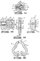
- Figure 1 is a side elevational view of the assembled femoral fixation appliance illustrating the implantation of the appliance in a femur.
- Figure 2 is a plan view of the cross nail of the appliance shown in Figure 1.
- Figure 3 is a cross section of the cross nail taken along line 3-3 of Figure 2.
- Figure 4 is a cross section of the cross nail taken along line 4-4 of Figure 3 and illustrating an unlocked condition of the intramedullary nail.
- Figure 5 is a cross section similar to Figure 4 showing the intramedullary nail in the locked condition thereof.
- Figure 6 is a cross section similar to Figure 4 illustrating dimensional relationships incorporated into the appliance.
- Figure 7 is a cross section of the cross nail taken along line 7-7 of Figure 5.
- Figure 8 is a side elevational view of a lower end portion of the intramedullary nail.
- Figure 9 is a cross section of the intramedullary nail taken along line 9-9 of Figure 8.
- Referring now to the drawings in general and to Figure 1 in particular, shown therein and designated by the
general reference numeral 10 is an appliance for fixing fractures of the femur constructed in accordance with the present invention. Afemur 12 has been drawn in dot-dash line in Figure 1 to illustrate the position of theappliance 10 after implantation in thefemur 12. - The
appliance 10 is comprised of across nail 14 which, when implanted in thefemur 12, extends generally from the base of the greater trochanter and into the head and neck of thefemur 12. An aperture 16 (Figures 2 and 3) is formed through thecross nail 14 to receive an intramedullary pin ornail 18 that extends downwardly into the intramedullary canal of the femur from a position slightly medial to the tip.of the greater trochanter as illustrated in Figure 1. Theappliance 10 is further comprised of a locking screw 20 (Figure 4) that firmly fixes theintramedullary nail 18 within theaperture 16 of thecross nail 14 in a manner that will be discussed below. - Referring now to Figures 2 and 3, shown therein is the construction of the
cross nail 14. As illustrated in these Figures, thecross nail 14, which is preferably machined from a bar of type 316L stainless steel, has aheel portion 22 adjacent oneend 24 of thecross nail 14. As can be seen in Figure 1, theend 24 is angled to lie flush with the outer surface of the lateral cortex when thecross nail 14 is implanted in a femur to extend along the axis of the femoral neck. Extending from theheel portion 22 to theopposite end 26 of thecross nail 14, thecross nail 14 is further comprised of ablade portion 28. As can be seen in Figures 2 and 3, theaperture 16 is positioned in theblade portion 28 and extends through thecross nail 14 at an angle to the blade portion that is substantially equal to the angle between the neck and shaft of the femur. Thus, theaperture 16 will align theintramedullary nail 18 with the intramedullary canal at such times that thecross nail 14 is implanted in thefemur 12 such that theblade portion 28 thereof extends generally parallel to the axis of the neck of the femur as illustrated in Figure 1. - One aspect of the present invention is the shaping of the
aperture 16 through thecross nail 14. In particular, and as shown in Figures 4 and 5, theaperture 16 is substantially D-shaped, theaperture 16 being defined by a flattened,internal surface 30 of theheel portion 22, thesurface 30 forming the flat side of the D, and asurface 32 of theblade portion 28 that extends arcuately between the ends of thesurface 30. - A threaded
bore 34 is formed longitudinally through upper portions of theheel portion 22 to intersect theend 24 of thecross nail 14 and theflattened surface 30 of theaperture 16, the axis of thebore 34 extending generally normally to theflattened surface 30 defining theaperture 16. Thebore 34 is counterbored from theend 24 of thecross nail 14 to form asocket 35 for a purpose to be discussed below. Ahole 36 is formed through theheel portion 22, also intersecting theend 24 of theheel portion 22 of thecross nail 14 and theflattened surface 30 defining theaperture 16, for a purpose also to be discussed below. - The
blade portion 28 of thecross nail 14 is rounded at theend 26, as shown in Figure 2, and has anupper surface 38 that slopes toward thelower side 40 from theheel portion 22 to theend 26 of thecross nail 14. Achannel 42 is cut in theupper surface 38 from theend 26 of thecross nail 14 to theaperture 16 so that theblade portion 28 has a generally U-shaped cross section throughout its length. Portions of theblade portion 28 about thesurface 32 are broadened to maintain a relatively thick wall for theblade portion 28 throughout the length thereof. Such construction of thecross nail 14 facilitates the implantation of thecross nail 14 in thefemur 12 while contributing to a strength and rigidity of theappliance 10 that will permit theappliance 10 to support the weight of the person in which theappliance 10 is implanted. - The construction of the
intramedullary nail 18 can best be seen from Figures 1, 8 and 9. Theintramedullary nail 18 is constructed by bending a metal strip, preferably composed of type 316L stainless steel, about the long axis of the strip so that theintramedullary nail 18 has the general form of an elongated tube as indicated in Figure 1. In the bending of the strip into a tube, a space is left between theside edges slit 48 extending the length of the intramedullary nail 1.8 is formed through the wall 50 of theintramedullary nail 18 at oneside 52 thereof. The width of theslit 48 is selected to coact with thelocking screw 20 in a manner that will be discussed below. Portions of the wall 50 of theintramedullary nail 18 adjacent theedges intramedullary nail 18 has a generally flattened construction, as indicated by theline 53 in Figure 9, along theside 52 of theintramedullary nail 18. As illustrated in Figure 4, theflattened side 52 of theintramedullary nail 18 is positioned adjacent theflattened surface 30 formed on theheel portion 22 of thecross nail 14 when theappliance 10 is assembled so that, when theintramedullary nail 18 is inserted through theaperture 16, theside 52 will co-act with thesurface 30 to maintain theslit 48 in alignment with the axis of the threadedbore 34 through theheel portion 22 of thecross nail 14. - The flattening of the
side 52 is preferably effected by providing theintramedullary nail 18 with a trifoliate cross section and forming theslit 48 between two petals of such cross section. To this end,concavities intramedullary nail 18 displaced from theslit 48, theconcavities intramedullary nail 18. The trifoliate cross section of theintramedullary nail 18 permits theintramedullary nail 18 to be constructed of a relatively light gauge metal while providing theintramedullary nail 18 with a rigidity sufficient to support the weight of the human body. The present invention contemplates that such rigidity will be exploited in the healing of severely comminuted fractures by using theappliance 10 to maintain the femur in internal traction during the healing of the fracture. In such cases, the femur is placed in traction by the mounting of thecross nail 14 in the upper portions of thefemur 12, rigidly securing upper end portions 58 (Figure 1) of theintramedullary nail 18 to thecross nail 14 in a manner to be discussed below, and by securinglower end portions 60 of theintramedullary nail 18 to lower portions of thefemur 12 in a manner shown in Figure 1. To this end and as shown in Figures 8 and 9, one ormore holes 62 are formed through the wall 50 in thelower end portion 60 of theintramedullary nail 18,such holes 62 being positioned opposite theside 52 of theintramedullary nail 18 through which theslit 48 is formed. The diameters of theholes 62 are made slightly larger than the width of theslit 48 andarcuate cuts 64 are formed in theedges slit 48 to align with theholes 62. In particular, thecuts 64 in theedges holes 62 to define, with theholes 62, one or more circular passages extending through theintramedullary nail 18 from theside 52 of theintramedullary nail 18 to the opposite side thereof. As shown in Figure 1, screws 66 can be passed through the passages formed by theholes 62 andcuts 64 to screw into lower portions of thefemur 12 when theappliance 10 is implanted in thefemur 12. As also shown in Figure 1, a rectangular hole 67 is formed through the wall of thenail 18 near the upper end thereof to facilitate removal of theappliance 10 from thefemur 12 after healing of the fracture has occurred. - Returning now to Figures 4 and 5, the locking
screw 20 and the manner of locking theintramedullary nail 18 to thecross nail 14 have been illustrated therein. As shown in such Figures, the lockingscrew 20 has ashank 68 that is provided with external threads to mate with the threads in thebore 34 formed through theheel portion 22 of thecross nail 14 so that the lockingscrew 20 can be screwed into thehole 34 of thecross nail 14. The lockingscrew 20 has anenlarged head 70 at one end thereof, thehead 70 having asocket 72 formed therein so that thescrew 20 can be turned in thebore 34 via a suitable wrench (not shown) having a portion to mate with thesocket 72. - As shown in Figure 5, the
head 70 enters thesocket 35 of theheel portion 22 when the lockingscrew 20 is screwed into thebore 34 to precisely position the lockingscrew 20 in theheel portion 22. The lockingscrew 20 has anose 74 at the other end thereof, thenose 74 being constructed in three portions. Immediately adjacent the end of the locking screw opposite thehead 70, thenose 74 has a rounded,small diameter portion 76 formed on a diameter substantially equal to the width of theslit 48 so that thesmall diameter portion 76 will freely enter theslit 48 when the lockingscrew 20 is screwed into thebore 34 with theintramedullary nail 18 inserted through theaperture 16 of thecross nail 14. Adjacent theshank 68 of the lockingscrew 20, thenose 74 has alarge diameter portion 78 that is formed on a diameter larger than the width of theslit 48. The twoportions nose 74 of the lockingscrew 20 are then connected by a taperedportion 80 that increases steadily in diameter from the diameter of theportion 76 to the diameter of theportion 78. - With the locking
screw 20 so constructed, the securing of thecross nail 14 to theintramedullary nail 18 is effected by screwing the lockingscrew 20 into thebore 34 until thehead 70 of thescrew 20 seats insocket 35. In particular, the lengths of theshank 68 and thenose 74 of the lockingscrew 20 are selected so that, when thehead 70 is seated in thesocket 35, the large diameter portion of thenose 74 will be extended into theslit 48 in the wall 50 of theintramedullary nail 18 to cause a spreading of theintramedullary nail 18 against portions of thecross nail 14 defining theaperture 16 as illustrated in Figure 5. Such spreading of theintramedullary nail 18 provides a strong frictional engagement between theintramedullary nail 18 and thecross nail 14 throughout the length of theaperture 16 which will provide a secure connection between theintramedullary nail 18 and thecross nail 14. - The securing of the
intramedullary nail 18 to thecross nail 14 in this manner is facilitated by the D-shape of theaperture 16, the flattening of theside 52 of theintramedullary nail 18, and by the selection of the combined length of theshank 68 andnose 74 of the lockingscrew 20. In particular, and as can be seen in Figure 4, the flattened construction of theside 52 of theintramedullary nail 18 and the D-shape of theaperture 16, coupled with a selection of the relative sizes of theintramedullary nail 18 and theaperture 16 such that the unexpandedintramedullary nail 18 will fit loosely within theaperture 16, will cause theslit 48 to align with the axis of thebore 34 in theheel portion 22 of thecross nail 14 when theintramedullary nail 18 is inserted through theaperture 16 with the flattenedside 52 thereof adjacent thesurface 30 on theheel portion 22 of thecross nail 14. When the lockingscrew 20 is then screwed into thebore 34, the small diameter portion of thenose 74 will engage the in-turned portions of the wall 50 of theintramedullary nail 18 adjacent theslit 48 and be cammed into theslit 48 so that theintramedullary nail 18 will be precisely oriented within theaperture 16 to precisely align theslit 48 with the axis of thebore 34. Further turning of the lockingscrew 20 into thebore 34 will cause the taperedportion 80 of thenose 74 of the lockingscrew 20 to enter theslit 48 and commence the expanding of the wall 50 of theintramedullary nail 18 against portions of thecross nail 14 defining theaperture 16. Such expansion continues while theenlarged diameter portion 78 of thenose 74 of the lockingscrew 20 enters theslit 48 to provide a maximum expansion of the wall 50 of theintramedullary nail 18 that firmly engages the wall 50 with portions of thecross nail 14 defining theaperture 16. Screwing of the lockingscrew 20 into thebore 34 is then continued until thehead 70 seats in thesocket 35 to rigidly secure the cross nail to the intramedullary nail. - The present invention further contemplates a second mode of locking of the
intramedullary nail 18 to thecross nail 14, preventing any sliding movement of thecross nail 14 along theintramedullary nail 18. As shown in Figure 6, thewidths aperture 16 andintramedullary nail 18 are chosen such that thewidth 82 exceeds thewidth 84 by a preselected amount when theintramedullary nail 18 is in an unexpanded state. Similarly, thediameter 86 of theenlarged portion 78 of thenose 74 of the lockingscrew 20 is made larger than thewidth 88 of theslit 48 by a preselected amount. In the preferred practice of the invention, the preselected amount by which thediameter 86 exceeds thewidth 88 exceeds the preselected amount by which thewidth 82 exceeds thewidth 84. Thus, when theenlarged diameter portion 78 of thenose 74 enters theslit 48, portions of the wall 50 of theintramedullary nail 28 aligned with thebore 34 are crumpled inwardly, as shown at 90 and 92 in Figure 5, to formarcuate depressions edges slit 48 about theenlarged portion 78 of thenose 74 of the lockingscrew 20. Thesedepressions cross nail 14 on theintramedullary nail 18 that is provided by the frictional engagement of theintramedullary nail 18 with portions of thecross nail 14 defining theaperture 16 that has been discussed above. - The crumpling of the
edges intramedullary nail 18 by theenlarged diameter portion 78 of the lockingscrew nose 74 further serves to fix the lockingscrew 20 to theintramedullary nail 18 preventing dislodgement of the lockingscrew 20. Specifically, the crumpledportions intramedullary nail 18 extend a distance along theenlarged diameter portion 78 of the lockingscrew nose 74 and are forced tightly against theportion 78 by the expansion of theintramedullary nail 18 against portions of thecross nail 14 defining theaperture 16 to form a frictional lock against dislodgement of the lockingscrew 20 from theintramedullary nail 18. - The locking
screw 20 is further locked securely to thecross nail 14 in a manner shown in Figure 5. In particular, the combined lengths of theshank 68 andnose 74 are selected to cause thenose 74 to engage portions of the inner surface of the wall 50 of theintramedullary nail 18 opposite theslit 48 when thehead 70 is seated and thereby force the threads on theshank 68 into firm engagement with the threads of thebore 34. Thus, once the lockingscrew 20 has been inserted to its maximum extent in thebore 34, a double lock preventing sliding movement of thecross nail 14 on theintramedullary nail 18 is formed so long as the lockingscrew 20 is emplaced in thecross nail 14 and a second double lock prevents dislodgement of the lockingscrew 20 from thecross nail 14. - For implantation of the
appliance 10, the patient is positioned on a fracture table in a supine position with both legs abducted and with the perineum resting against a radiolucent centerpost on the table. The uninjured lower extremity is then elevated and placed in a stirrup so that good lateral radiographs of the hip can be obtained with an image intensifier. The injured lower extremity is then placed in distal traction either through a boot attached to an extension device or through Kirschner wire in either the tibia or the distal femur. In cases involving a shaft fracture, such fracture can be checked with an image intensifier and a crutch can be used to aid in the reduction of the shaft portion of the fracture. Thereafter, the image intensifier is moved to the hip to enable the physician to observe the position of the hip fracture that theappliance 10 is constructed to fix. Following the positioning of the patient on the fracture table, the entire thigh and hip is prepped with Betadine prep and draped with a large laparotomy sheet. - To commence the implantation of the
appliance 10 in a fractured hip, an incision having a length of approximately three centimeters is made over the tip of the greater trochanter to permit opening of the intramedullary canal of the proximal femur with an awl. Such opening is made slightly medially of the tip of the greater trochanter and in line with the central axis of the femoral neck slightly anteriorly and laterally of the obturator fossa and the awl is inserted into the intramedullary canal to a depth of two to five centimeters generally in a direction toward the curved axis of the femur. The awl is then replaced with a ballpoint guide pin which is extended into the femoral shaft across the site of any shaft fractures which may have occurred. During such positioning of the guide pin, the position of the pin with respect to fracture fragments through the region of the hip is checked using the image intensifier in two planes and the image intensifier is similarly utilized to observe the guide pin as the guide pin is manipulated down the femoral shaft and across the site of shaft fractures which might be present. - Following the insertion of the guide pin, the entry portal to the intramedullary canal that has been formed is enlarged by means of a reamer awl inserted over the guide pin. The reamer awl is then removed and the femoral shaft is reamed with a flexible reamer to a diameter slightly larger than the diameter of the
intramedullary nail 18 to be used in the fixation of the fracture. In particular, the femoral canal is reamed to a diameter of approximately, one-half millimeter to one millimeter larger than the diameter of theintramedullary nail 18, the upper end of the range being necessary when the patient is young or when the bone is extremely hard. The over- reaming of the intramedullary canal will prevent twisting of theintramedullary nail 18 when thenail 18 is subsequently driven down the femoral shaft. - After the reaming of the femoral canal is completed, and the guide wire is removed from the canal, the image intensifier is repositioned at the hip at a 45° angle to the long axis of the femur. A second incision is then made laterally over the base of the greater trochanter to extend distally for a few centimeters and such incision is carried down to the base of the greater trochanter. An important aspect of the present invention is that the second incision is limited to the region of the base of the greater trochanter to limit the avenue for infection that the incision provides and, in particular, to eliminate an avenue for infection to fragments of the femur disposed distally of the intertrochanter region.
- A guide wire is then inserted into the proximal femur at an angle of approximately 135° to extend substantially along the center of the femoral neck. A first hole is then formed in the femur to a depth approximately equal to the length of the
heel portion 22 of thecross nail 14 via a cannulated portal reamer that is placed over the guide wire. Once the first hole has been formed, a portal guide or jig (not shown), having two vertically spaced holes is mounted on the guide wire, via the lower hole of the portal guide, and a protruding portion of the portal guide is driven into the first hole laterally in the femur. The portal guide is then fixed to the femur with a secondary Kirschner wire. The second hole is then formed in the femur above the first hole via a portal reamer that is inserted through the upper hole of the portal guide. The two holes through the portal guide are so spaced that the two holes formed in the femur will overlap to form an elliptical hole that will receive theheel portion 22 and widened portions of theblade portion 28 of thecross nail 14 adjacent theheel portion 22 thereof. To this end, the second hole is drilled only to a depth sufficient to receive theheel portion 22 and widened portions of theblade portion 28. The secondary Kirschner wire and the portal guide are then removed from the femur. The formation of the two holes in the positions thus described will permit thecross nail 14 to be driven into the neck and head of the femur in a position that has been indicated in Figure 1. In particular, thecross nail 14 will extend substantially along the axis of the femoral neck just above the calcar femorale following the implantation of the cross nail in the femur. - Following the removal of the portal guide, the
cross nail 14 is placed over the guide wire extending into the femoral neck via thehole 36 formed through theheel portion 22 of thecross nail 14 and thecross nail 14 is driven into the femoral neck. The driving of thecross nail 14 into the femoral neck can be facilitated by a tool (not shown) having a slanted end to mate with theslanted end 24 of thecross nail 14 and having a hole that will align with the threaded bore 34 so that the tool can be connected to thecross nail 14 via a screw (not shown) that screws into thebore 34. As shown in Figure 3, a portion of thehole 36 that intersects theend 24 of thecross nail 14 is counterbored to receive a projection that can be formed on the driving tool to eliminate any relative motion between the driving tool and thecross nail 14. - Once the
cross nail 14 has been driven into the femoral neck and head, the driving tool is removed and replaced with a tool (not shown) that screws to theend 24 of thecross nail 14, via thebore 34, and has a portion that extends upwardly over theaperture 16 formed through thecross nail 14. Such portion has a hole that aligns with theaperture 16 so that a drill can be passed through the hole in such tool and into theaperture 16 to provide a straight path down through the tip of the greater trochanter and theaperture 16 through thecross nail 14. - Following the final alignment of the
aperture 16 with the entry hole from the tip of the greater trochanter, the guide tool is removed from thecross nail 14 and a ball tipped guide wire is inserted from the tip of the greater trochanter into the femoral canal and manipulated across fracture sites that may be present in the femur. Such manipulation is observed using the image intensifier and is utilized to position the guide wire such that fragments of the femur will be positioned about the guide wire in substantially the position that such fragments would occupy about the axis of the intramedullary canal in an undamaged femur. Theintramedullary nail 18 is then placed over the guide wire with the flattenedside 52 thereof directed toward the flattenedsurface 30 of theheel portion 22 of thecross nail 14 and theintramedullary nail 18 is driven into the intramedullary canal to a depth sufficient to leave approximately one centimeter of theintramedullary nail 18 extending from the top of the femur as indicated in Figure 1. During the driving of theintramedullary nail 18, it is helpful to tap thecross nail 14 in order to prevent the formation of a sliding lock between theintramedullary nail 18 and thecross nail 14 as theintramedullary nail 18 is driven. Once theintramedullary nail 18 has been driven into the intramedullary canal, the guide wire is removed and the lockingscrew 20 is screwed into thebore 34 to securely fix theintramedullary nail 18 to thecross nail 14 in the manner described below. - Following the implantation of the
appliance 10 in the femur, thelower end portion 60 of theintramedullary nail 18 is secured to lower portions of the femoral shaft. To this end, the image intensifier is repositioned distally to permit the physician to observe theholes 62 through thelower end portion 60 of theintramedullary nail 18. In particular, the image intensifier is positioned such that the image of thecuts 64 align with the image of theholes 62 thereby insuring that the axis of the image intensifier is precisely aligned perpendicularly to theintramedullary nail 18 so that the image intensifier can be used as a guide for drilling holes through the lower portion of the femur in alignment with the passages formed through thelower end portion 60 of theintramedullary nail 18 via theholes 62 and thecuts 64. Following the alignment of the image intensifier, a stab wound is made laterally in the skin and down through the fascialata to receive a drill sleeve that extends to lower portions of the femur. The position of the drill sleeve is checked with lateral and anterior/posterior radiographs obtained with the image intensifier to provide a precise alignment between the drill guide and the passages through thelower end portion 60 of theintramedullary nail 18. Holes are then drilled through the lateral cortex of the femur to pass through the passages in the lower end portion of theintramedullary nail 18 and thence through the medial cortex. Thescrews 66 are then inserted into the stab wounds through which the holes through the femur were drilled and screwed into the lateral cortex, through thelower end portion 60 of theintramedullary nail 18, and into the medial cortex in a manner that has been shown in Figure 1. With thescrews 66 thus extending both through portions of the femur and lower end portions of theintramedullary nail 18, theappliance 10 will be securely fixed to both the distal and proximal ends of thefemur 12 and such fixation will have occurred while the femur is maintained in traction. Thus, in addition to fixing fragments of the femur in the intertrochanteric area, theappliance 10 will also have aligned and positioned fragments of the femur in the subtrochanteric and shaft portions thereof about theintramedullary nail 18 to position all fragments of the femur in substantially the positions such fragments occupy in the uninjured femur to permit the formation of a callus about the fragments to reform the femur into substantially the same configuration that existed prior to the fracture. Following the securing of thelower end portion 60 of theintramedullary nail 18 to the distal portion of the femur, the wounds made in the hip and thigh are closed in the standard fashion. - Aftercare of fractures of the type that are fixed using the
appliance 10 consists of allowing the patient to be ambulatory on crutches and allowing at least touchdown of the leg in which theappliance 10 has been implanted. However, full weight bearing on such leg is delayed until substantial healing of the fracture has occurred to prevent the full weight of the body from being borne by thescrews 66. By this means, the securing of theappliance 10 to both the distal and proximal ends of the femur will insure that the femur is maintained in traction to consequently insure appropriate knitting of the fragmehts of the femur. During the period in which the femur heals, physiotherapy involving the full range of motion to the hip and knee is commenced to promote early mobility of the patient. It is recommended that such physiotherapy be commenced as soon post-operatively as the patient can tolerate. - It will be clear that the present invention is well adapted to carry out the objects and attain the ends and advantages mentioned as well as those inherent therein. While a presently preferred embodiment of the invention has been described for purposes of this disclosure, numerous changes may be made which will readily suggest themselves to those skilled in the art and which are encompassed within the scope of the invention disclosed and as defined in the appended claims.
Claims (21)
Applications Claiming Priority (2)
| Application Number | Priority Date | Filing Date | Title |
|---|---|---|---|
| US690777 | 1985-01-11 | ||
| US06/690,777 US4697585A (en) | 1985-01-11 | 1985-01-11 | Appliance for fixing fractures of the femur |
Publications (2)
| Publication Number | Publication Date |
|---|---|
| EP0192840A1 EP0192840A1 (en) | 1986-09-03 |
| EP0192840B1 true EP0192840B1 (en) | 1990-08-08 |
Family
ID=24773922
Family Applications (1)
| Application Number | Title | Priority Date | Filing Date |
|---|---|---|---|
| EP85115748A Expired EP0192840B1 (en) | 1985-01-11 | 1985-12-11 | Appliance for fixing fractures of the femur |
Country Status (3)
| Country | Link |
|---|---|
| US (1) | US4697585A (en) |
| EP (1) | EP0192840B1 (en) |
| DE (1) | DE3579151D1 (en) |
Families Citing this family (73)
| Publication number | Priority date | Publication date | Assignee | Title |
|---|---|---|---|---|
| DE8534358U1 (en) * | 1985-12-06 | 1986-01-23 | Howmedica GmbH Werk Schönkirchen, 2314 Schönkirchen | Bone nail for treating upper arm fractures |
| US4776330A (en) * | 1986-06-23 | 1988-10-11 | Pfizer Hospital Products Group, Inc. | Modular femoral fixation system |
| DE3730570A1 (en) * | 1987-09-11 | 1989-03-23 | Kernforschungsz Karlsruhe | Nail for fixing proximal femoral fractures |
| US4846162A (en) * | 1987-09-14 | 1989-07-11 | Moehring H David | Orthopedic nail and method of bone fracture fixation |
| GB8722370D0 (en) * | 1987-09-23 | 1987-10-28 | Halder S C | Fixating device |
| US5176681A (en) * | 1987-12-14 | 1993-01-05 | Howmedica International Inc. | Intramedullary intertrochanteric fracture fixation appliance and fitting device |
| US4875474A (en) * | 1988-01-29 | 1989-10-24 | Biomet, Inc. | Variable wall thickness interlocking intramedullary nail |
| US5066296A (en) * | 1989-02-02 | 1991-11-19 | Pfizer Hopsital Products Group, Inc. | Apparatus for treating a fracture |
| US5034013A (en) * | 1989-04-24 | 1991-07-23 | Zimmer Inc. | Intramedullary nail |
| US4993410A (en) * | 1989-05-01 | 1991-02-19 | Kimsey Timothy P | Prosthetic removal device |
| US4978349A (en) * | 1989-08-03 | 1990-12-18 | Synthes (U.S.A.) | Fixation plate |
| US4946459A (en) * | 1989-12-04 | 1990-08-07 | Georgia Tech Research Corporation | Intramedullary device |
| US5032125A (en) * | 1990-02-06 | 1991-07-16 | Smith & Nephew Richards Inc. | Intramedullary hip screw |
| US5053035A (en) * | 1990-05-24 | 1991-10-01 | Mclaren Alexander C | Flexible intramedullary fixation rod |
| US5100404A (en) * | 1990-09-04 | 1992-03-31 | Beth Israel Hospital | Intramedullary nailing method and apparatus |
| GB9113578D0 (en) * | 1991-06-24 | 1991-08-14 | Howmedica | Intramedullary intertrochanteric fracture fixation appliance |
| DE9109883U1 (en) * | 1991-08-09 | 1991-09-26 | Howmedica Gmbh, 2314 Schoenkirchen, De | |
| DE4318150C2 (en) * | 1993-06-01 | 1996-08-01 | Endocare Ag | Osteosynthesis tools for the treatment of subtrochanteric and pertrochanteric fractures as well as fractures of the femoral neck |
| US5484439A (en) * | 1992-09-16 | 1996-01-16 | Alphatec Manufacturing, Inc. | Modular femur fixation device |
| DE29804268U1 (en) | 1998-03-11 | 1998-05-14 | Synthes Ag | Spiral blade insertion instrument |
| US6494913B1 (en) | 1998-03-17 | 2002-12-17 | Acumed, Inc. | Shoulder prosthesis |
| DE19900133A1 (en) * | 1999-01-05 | 2000-07-06 | Intraplant Ag Cham | System for positioning and locking an intramedullary force carrier, in particular intramedullary nail |
| US6221074B1 (en) | 1999-06-10 | 2001-04-24 | Orthodyne, Inc. | Femoral intramedullary rod system |
| US7018380B2 (en) * | 1999-06-10 | 2006-03-28 | Cole J Dean | Femoral intramedullary rod system |
| AU2001231272A1 (en) | 2000-02-02 | 2001-08-14 | Owen A. Nelson | An orthopedic implant used to repair intertrochanteric fractures and a method for inserting the same |
| US6235031B1 (en) | 2000-02-04 | 2001-05-22 | Encore Medical Corporation | Intramedullary fracture fixation device |
| DE20003053U1 (en) | 2000-02-19 | 2001-06-28 | Howmedica Gmbh | Locking nail and aiming device |
| US6409730B1 (en) | 2000-05-31 | 2002-06-25 | Synthes (Usa) | Humeral spiral blade |
| US6527775B1 (en) | 2000-09-22 | 2003-03-04 | Piper Medical, Inc. | Intramedullary interlocking fixation device for the distal radius |
| US6652529B2 (en) | 2001-09-12 | 2003-11-25 | Todd V. Swanson | Method and apparatus for treating supracondylar fractures of the femur |
| US6835197B2 (en) * | 2001-10-17 | 2004-12-28 | Christoph Andreas Roth | Bone fixation system |
| DE10227379B4 (en) * | 2002-06-20 | 2005-12-08 | Stryker Trauma Gmbh | Implantation system and target device for it |
| WO2004078049A1 (en) * | 2003-03-07 | 2004-09-16 | Synthes Ag Chur | Locking screw for an intramedullary nail |
| JP4357478B2 (en) * | 2003-06-12 | 2009-11-04 | ジンテーズ ゲゼルシャフト ミト ベシュレンクテル ハフツング | Surgical nail |
| DE50312960D1 (en) * | 2003-06-12 | 2010-09-16 | Synthes Gmbh | SURGICAL NAIL |
| ATE418923T1 (en) * | 2003-07-30 | 2009-01-15 | Synthes Gmbh | SURGICAL NAIL |
| CN100479775C (en) * | 2003-08-29 | 2009-04-22 | 斯恩蒂斯有限公司 | Intramedullary nail |
| NZ546545A (en) * | 2003-10-21 | 2008-11-28 | Synthes Gmbh | Intramedullary nail |
| AU2004320725A1 (en) * | 2004-06-22 | 2005-12-29 | Synthes Gmbh | Intramedullary nail |
| CA2571672C (en) * | 2004-06-24 | 2012-08-28 | Synthes (U.S.A.) | Intramedullary nail |
| US8066706B2 (en) * | 2004-06-30 | 2011-11-29 | Synthes Usa, Llc | Surgical nail |
| US7588577B2 (en) | 2004-07-15 | 2009-09-15 | Wright Medical Technology, Inc. | Guide assembly for intramedullary fixation and method of using the same |
| US20060015101A1 (en) | 2004-07-15 | 2006-01-19 | Wright Medical Technology, Inc. | Intramedullary fixation assembly and devices and methods for installing the same |
| US9060820B2 (en) | 2005-05-18 | 2015-06-23 | Sonoma Orthopedic Products, Inc. | Segmented intramedullary fracture fixation devices and methods |
| US8287541B2 (en) | 2005-05-18 | 2012-10-16 | Sonoma Orthopedic Products, Inc. | Fracture fixation device, tools and methods |
| US7909825B2 (en) | 2006-11-22 | 2011-03-22 | Sonoma Orthepedic Products, Inc. | Fracture fixation device, tools and methods |
| AU2006247498A1 (en) | 2005-05-18 | 2006-11-23 | Sonoma Orthopedic Products, Inc. | Minimally invasive actuable bone fixation devices, systems and methods of use |
| US8961516B2 (en) | 2005-05-18 | 2015-02-24 | Sonoma Orthopedic Products, Inc. | Straight intramedullary fracture fixation devices and methods |
| GB2445346B (en) * | 2005-10-21 | 2011-03-09 | Acumed Llc | Orthopedic rod with locking aperture |
| WO2007133643A2 (en) * | 2006-05-10 | 2007-11-22 | Concepts In Medicine, Llc | Modular, blade-rod, intramedullary fixation device |
| CN101677831B (en) * | 2007-05-25 | 2011-07-20 | 齐默尔有限公司 | Reinforced intramedullary nail |
| DE102007029090A1 (en) * | 2007-06-21 | 2008-12-24 | Plus Orthopedics Ag | Device for osteosynthesis, particularly bone fracture near joint, has pin for implantation into abarticular bone, and proximal longitudinal ring element provided for implantation into bone fragment near joint |
| US8206389B2 (en) * | 2007-08-31 | 2012-06-26 | Huebner Randall J | Rod-based system for bone fixation |
| US8771283B2 (en) | 2007-12-17 | 2014-07-08 | Wright Medical Technology, Inc. | Guide assembly for intramedullary fixation and method of using the same |
| EP2341857A2 (en) | 2008-09-26 | 2011-07-13 | Sonoma Orthopedic Products, Inc. | Bone fixation device, tools and methods |
| JP5634501B2 (en) * | 2009-05-05 | 2014-12-03 | シンセス ゲゼルシャフト ミット ベシュレンクテル ハフツングSynthes Gmbh | Nail locking system |
| DE102013005414A1 (en) * | 2013-03-28 | 2014-10-02 | Dietmar Wolter | Osteosynthesis system for the multidirectional, angularly stable treatment of fractures of long bones including an intramedullary nail and bone screws |
| US9770278B2 (en) | 2014-01-17 | 2017-09-26 | Arthrex, Inc. | Dual tip guide wire |
| US9517094B1 (en) * | 2014-05-09 | 2016-12-13 | Savage Medical Design LLC | Intramedullary fixation apparatus for use in hip and femur fracture surgery |
| US9814499B2 (en) | 2014-09-30 | 2017-11-14 | Arthrex, Inc. | Intramedullary fracture fixation devices and methods |
| TWI589263B (en) * | 2015-06-04 | 2017-07-01 | 愛派司生技股份有限公司 | A fixation system for hip fracture use thereof |
| US10492838B2 (en) | 2015-07-13 | 2019-12-03 | IntraFuse, LLC | Flexible bone implant |
| US10499960B2 (en) | 2015-07-13 | 2019-12-10 | IntraFuse, LLC | Method of bone fixation |
| US10154863B2 (en) | 2015-07-13 | 2018-12-18 | IntraFuse, LLC | Flexible bone screw |
| US10485595B2 (en) | 2015-07-13 | 2019-11-26 | IntraFuse, LLC | Flexible bone screw |
| WO2018069554A1 (en) * | 2016-10-10 | 2018-04-19 | Ferrero Manzanal Francisco | Intramedullary nailing system of variable angle to treat femur fractures |
| CA3055959A1 (en) | 2017-03-10 | 2018-09-13 | Exactech, Inc. | Platform fracture fixation implants |
| CN111447885B (en) * | 2017-10-09 | 2023-10-20 | 精密医疗责任有限公司 | System and method for bone fixation using staples locked into surrounding anchors |
| CA3078249A1 (en) | 2017-10-11 | 2019-04-18 | Tornier, Inc. | Humeral fixation plate guides |
| CN109662769A (en) * | 2018-11-30 | 2019-04-23 | 陈聚伍 | Through towed Medullary fixation device |
| CN109805995B (en) * | 2019-04-11 | 2024-01-26 | 吴丹凯 | Bundling and fixing device based on proximal femur intramedullary nail system |
| CN110464441B (en) * | 2019-08-29 | 2024-03-15 | 深圳市儿童医院 | Auxiliary reduction device for femur fracture |
| CN112057154B (en) * | 2020-09-11 | 2022-02-18 | 天津市威曼生物材料有限公司 | Femoral internal fixation system |
Family Cites Families (15)
| Publication number | Priority date | Publication date | Assignee | Title |
|---|---|---|---|---|
| US2675801A (en) * | 1954-04-20 | Intramedbllary nail | ||
| US2136471A (en) * | 1937-06-30 | 1938-11-15 | Rudolph H Schneider | Bone pin |
| US2406987A (en) * | 1943-01-04 | 1946-09-03 | Anderson Roger | Fracture splint |
| DE913228C (en) * | 1943-12-14 | 1954-06-10 | Dr Med H C Ernst Pohl | Cross elastic inner splint for tubular bones |
| US2821979A (en) * | 1953-05-18 | 1958-02-04 | William E Stapp | Intramedullary splint |
| US2947308A (en) * | 1956-11-02 | 1960-08-02 | Harry A Gorman | Hip joint prosthesis |
| US3433220A (en) * | 1966-12-30 | 1969-03-18 | Robert E Zickel | Intramedullary rod and cross-nail assembly for treating femur fractures |
| US3561437A (en) * | 1967-11-08 | 1971-02-09 | Jose Luis Orlich | Apparatus for fixing fractures of the femur |
| US3893196A (en) * | 1970-08-06 | 1975-07-08 | Robert F Hochman | Body implant material |
| AT363172B (en) * | 1979-09-07 | 1981-07-10 | Novex Foreign Trade Co Ltd | MARKHOEHLENNAGEL |
| CH642252A5 (en) * | 1980-01-14 | 1984-04-13 | Sulzer Ag | LEAFY SHAFT FOR ANCHORING A HIP JOINT PROSTHESIS. |
| AT384359B (en) * | 1981-12-01 | 1987-11-10 | Ender Hans Georg | BONE NAIL |
| US4457301A (en) * | 1982-06-18 | 1984-07-03 | Howmedica Inc. | Intramedullary fixation device |
| US4475545A (en) * | 1982-12-06 | 1984-10-09 | Ender Hans G | Bone-nail |
| EP0186656B1 (en) * | 1983-03-09 | 1989-09-20 | HOWMEDICA INTERNATIONAL, INC. Zweigniederlassung Kiel | Anchorage nail |
-
1985
- 1985-01-11 US US06/690,777 patent/US4697585A/en not_active Expired - Lifetime
- 1985-12-11 DE DE8585115748T patent/DE3579151D1/en not_active Expired - Lifetime
- 1985-12-11 EP EP85115748A patent/EP0192840B1/en not_active Expired
Also Published As
| Publication number | Publication date |
|---|---|
| DE3579151D1 (en) | 1990-09-13 |
| EP0192840A1 (en) | 1986-09-03 |
| US4697585A (en) | 1987-10-06 |
Similar Documents
| Publication | Publication Date | Title |
|---|---|---|
| EP0192840B1 (en) | Appliance for fixing fractures of the femur | |
| US11090098B2 (en) | Systems and methods for intramedullary nail implantation | |
| US11730524B2 (en) | Systems and methods for intramedullary nail implantation | |
| US6524313B1 (en) | Intramedullary nail system | |
| US7942875B2 (en) | Methods of using minimally invasive actuable bone fixation devices | |
| CA2350083C (en) | Intramedullary nail for the operative treatment of fractures of the lower arm | |
| EP2175790A2 (en) | A bolt apparatus | |
| US20210353349A1 (en) | Systems and methods for intramedullary nail implantation | |
| WO2018029374A1 (en) | An orthopaedic device | |
| US20220202464A1 (en) | Systems and methods for intramedullary nail implantation | |
| US11583328B2 (en) | Femoral nail and instrumentation system | |
| EP3636175A2 (en) | Systems for intramedullary nail implantation | |
| EP4215131A1 (en) | Systems for intramedullary nail implantation | |
| EP3747375A1 (en) | Systems for intramedullary nail implantation | |
| RU70785U1 (en) | DEVICE FOR OSTEOSYNTHESIS OF CERVICAL, HELICOPTER AND PREPARATIVE FEMORAL FRACTURES |
Legal Events
| Date | Code | Title | Description |
|---|---|---|---|
| PUAI | Public reference made under article 153(3) epc to a published international application that has entered the european phase |
Free format text: ORIGINAL CODE: 0009012 |
|
| AK | Designated contracting states |
Kind code of ref document: A1 Designated state(s): CH DE FR GB LI SE |
|
| 17P | Request for examination filed |
Effective date: 19870206 |
|
| 17Q | First examination report despatched |
Effective date: 19880921 |
|
| 17Q | First examination report despatched |
Effective date: 19890616 |
|
| GRAA | (expected) grant |
Free format text: ORIGINAL CODE: 0009210 |
|
| AK | Designated contracting states |
Kind code of ref document: B1 Designated state(s): CH DE FR GB LI SE |
|
| PG25 | Lapsed in a contracting state [announced via postgrant information from national office to epo] |
Ref country code: SE Free format text: THE PATENT HAS BEEN ANNULLED BY A DECISION OF A NATIONAL AUTHORITY Effective date: 19900808 Ref country code: LI Effective date: 19900808 Ref country code: FR Effective date: 19900808 Ref country code: CH Effective date: 19900808 |
|
| REF | Corresponds to: |
Ref document number: 3579151 Country of ref document: DE Date of ref document: 19900913 |
|
| REG | Reference to a national code |
Ref country code: CH Ref legal event code: PL |
|
| EN | Fr: translation not filed | ||
| PLBE | No opposition filed within time limit |
Free format text: ORIGINAL CODE: 0009261 |
|
| STAA | Information on the status of an ep patent application or granted ep patent |
Free format text: STATUS: NO OPPOSITION FILED WITHIN TIME LIMIT |
|
| 26N | No opposition filed | ||
| PGFP | Annual fee paid to national office [announced via postgrant information from national office to epo] |
Ref country code: GB Payment date: 19951110 Year of fee payment: 11 |
|
| PGFP | Annual fee paid to national office [announced via postgrant information from national office to epo] |
Ref country code: DE Payment date: 19951129 Year of fee payment: 11 |
|
| PG25 | Lapsed in a contracting state [announced via postgrant information from national office to epo] |
Ref country code: GB Effective date: 19961211 |
|
| GBPC | Gb: european patent ceased through non-payment of renewal fee |
Effective date: 19961211 |
|
| PG25 | Lapsed in a contracting state [announced via postgrant information from national office to epo] |
Ref country code: DE Effective date: 19970902 |