EP0193231A1 - Projection-lens system - Google Patents
Projection-lens system Download PDFInfo
- Publication number
- EP0193231A1 EP0193231A1 EP86200216A EP86200216A EP0193231A1 EP 0193231 A1 EP0193231 A1 EP 0193231A1 EP 86200216 A EP86200216 A EP 86200216A EP 86200216 A EP86200216 A EP 86200216A EP 0193231 A1 EP0193231 A1 EP 0193231A1
- Authority
- EP
- European Patent Office
- Prior art keywords
- lens
- projection
- aspheric
- lens system
- image side
- Prior art date
- Legal status (The legal status is an assumption and is not a legal conclusion. Google has not performed a legal analysis and makes no representation as to the accuracy of the status listed.)
- Granted
Links
Images

Classifications
-
- G—PHYSICS
- G02—OPTICS
- G02B—OPTICAL ELEMENTS, SYSTEMS OR APPARATUS
- G02B13/00—Optical objectives specially designed for the purposes specified below
- G02B13/16—Optical objectives specially designed for the purposes specified below for use in conjunction with image converters or intensifiers, or for use with projectors, e.g. objectives for projection TV
-
- G—PHYSICS
- G02—OPTICS
- G02B—OPTICAL ELEMENTS, SYSTEMS OR APPARATUS
- G02B13/00—Optical objectives specially designed for the purposes specified below
- G02B13/04—Reversed telephoto objectives
-
- G—PHYSICS
- G02—OPTICS
- G02B—OPTICAL ELEMENTS, SYSTEMS OR APPARATUS
- G02B7/00—Mountings, adjusting means, or light-tight connections, for optical elements
- G02B7/008—Mountings, adjusting means, or light-tight connections, for optical elements with means for compensating for changes in temperature or for controlling the temperature; thermal stabilisation
-
- G—PHYSICS
- G02—OPTICS
- G02B—OPTICAL ELEMENTS, SYSTEMS OR APPARATUS
- G02B9/00—Optical objectives characterised both by the number of the components and their arrangements according to their sign, i.e. + or -
- G02B9/12—Optical objectives characterised both by the number of the components and their arrangements according to their sign, i.e. + or - having three components only
-
- G—PHYSICS
- G02—OPTICS
- G02B—OPTICAL ELEMENTS, SYSTEMS OR APPARATUS
- G02B9/00—Optical objectives characterised both by the number of the components and their arrangements according to their sign, i.e. + or -
- G02B9/34—Optical objectives characterised both by the number of the components and their arrangements according to their sign, i.e. + or - having four components only
Definitions
- the invention relates to a projection-lens system for projecting a magnified image of a scene reproduced by means of a reproduction element onto a projection screen, which lens system comprises, in this order and viewed from the image side, a first group of lenses, of which at least one outer surface is aspheric, a positive second or main group, of which at least the outer surface which faces the object side is aspheric, and a third group comprising a negative lens whose surface which faces the image side is concave and aspheric, the elements of the first group and the third group being made of a transparent plastics.
- the invention also relates to a colour-television projection system comprising at least one projection-lens system of this kind.
- Such a projection-lens system is disclosed in United States Patent Specification No. 4,348,081 and is intended for projecting a scene in one colour on a projection screen, where three monochrome images are superimposed to form a colour picture, for example a colour-television picture.
- the third group comprises a planoconcave lens, also referred to as a field-curvature correction lens or "field flattener", which compensates for the Petzvat curvature of the two other lens groups.
- the main group may be a single biconvex lens or may comprise two spaced single positive lenses.
- the lens system in accordance with United States Patent Specification No. 4,348,081 is not achromatic. Moreover, in particular in the versions comprising three lenses, the modulation transfer function in the field comers is minimal and the luminance is not satisfactory.
- the first group and the third group which are made of a transparent plastics whose refractive index varies with the temperature, so that the focal length of the entire system is still temperature dependent.
- the projection-lens system in accordance with the invention is characterized in that the main group provides substantially the entire power of the system and comprises at least one glass lens substrate, at least that outer surface of said substrate which faces the object side being provided with a layer of a transparent plastics having an aspheric outer profile.
- the invention is based inter alia on the recognition of the fact that the temperature-independent high-quality main group with aspheric refractive surfaces required in a projection-fens system can be manufactured comparatively cheaply by the use of a glass preform or lens substrate which is provided with one layer or two layers of a transparent plastics having aspheric outer profiles by means of a replica or copying method using dies having aspheric profiles.
- a projection-lens system having a small focal length and a large angle of field.
- the term angle of field is to be understood to mean the angle between the optical axis and the chief ray of a beam which issues from the edge of the object or scene and which is still accepted by the system.
- a preferred embodiment of the projection-lens system in accordance with the invention is characterized further in that the main group comprises a cemented doublet of a biconvex lens and a concavo-convex lens, whose lens substrates have substantially equal refractive indices and different dispersions.
- This system has the advantage that the axial chromatic aberration is substantially smaller than in the projection-lens systems known until now.
- the axial chromatic aberration is to be understood to mean the variation in the axial position of the image as a function of the wavelength of the radiation used.
- An important practical aspect of the projection-tens system in accordance with the invention is that it is possible to design the system in such a way that the diameter of the lens elements decreases, viewed from the object side.
- the monochrome images should be superimposed on the projection screen, the reproduction tubes, which are arranged in-line, should be inclined towards one another, Le-the normals to the two outer reproduction tubes should make a specific angle with the normal to the centre reproduction tube. If the diameters of the lens elements decrease towards the image side, i.e. in the case that the projection lens system is trough-shaped, this angle can be smaller than in conventional projection-lens systems. Reducing this angle is favourable in view of the optical properties of the projection screen.
- An embodiment of the projection lens system in accordance with the invention in which the two outer surfaces of the main group are provided with an aspheric layer of a transparent plastics exhibits very good properties. Surprisingly, it has been found that it is possible to obtain practically the same good properties if only one of the outer surfaces of the main group is provided with an aspheric layer.
- the projection-tens system in accordance with the invention may be characterized further in that the third group comprises two tenses, of which the lens at the image side is a meniscus lens whose concave surface faces the image side and of which the second lens is a planoconcave lens whose concave surface faces the image side, and the concave surfaces of both lenses are aspheric.
- the projection-tens system in accordance with the invention is characterized further in that the third group comprises one meniscus lens whose power is substantially zero and whose convex surface faces the image side.
- the colour-television projection system shown in Fig. 1 comprises a colour television receiver 1.
- An input of this receiver which is coupled to, for example, an aerial 2, receives a colour television signal, which is divided into a red signal, a green signal and a blue signal.
- These signals are applied to three separate reproduction tubes, in the present example three cathode-ray tubes 3, 4 and 5, on whose fluorescent screens a red picture, a green picture and a blue picture appear.
- the schematically shown projection-lens systems 6, 7 and 8 associated with the reproduction tubes project these pictures onto a projection screen 10. For the sake of clarity only the chief rays of the beams emitted by the reproduction tubes are shown.
- a mirror 9 is arranged between the projection-lens systems and the projection screen and reflects the upwardly inclined beams from the cathode-ray tubes to the projection screen. This mirror folds the radiation path, so that the projection system can be accommodated in a cabinet of comparatively small depth without thereby reducing the length of the radiation path.
- the three monochrome pictures must be superimposed on the projection screen.
- the reproduction tubes which are arranged in-line, are slightly inclined towards one another, i.e. the normals to the screens of the tubes 3 and 5 make a small angle with the normal to the screen of the tube 4.
- the radiation of the three beams is scattered over a comparatively large angle in the Y-direction, which is the horizontal direction for the viewer W, and over a smaller angle in the Z-direction, which is the vertical direction for the viewer.
- the viewer W sees a picture which is a superposition of the enlarged images formed by means of the reproduction tubes.
- Each of the projection lenses 3, 4 and 5 should image the scene on the screen of the associated reproduction tube on the projection screen with a high image quality out to the edges of the picture.
- Such a projection-tens system should have a large numerical aperture and the image distance corresponding to a specific magnification should be as small as possible.
- the lenses of the projection-lens system are comparatively large, so that it is desirable to make these lenses of light-weight materials.
- the number of lens elements should be minimal, at least some of these elements must have aspheric refractive surfaces in order to ensure that the projection-lens system is adequately corrected and has a satisfactory optical transfer function.
- the focal length of the entire projection-lens system should be temperature-independent and should remain constant over a wide range of wavelengths.
- the present invention provides a class of projection-lens systems by means of which the above-mentioned partly conflicting requirements are met in an optimum manner.
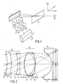
- Fig. 2 shows a projection-lens system in accordance with a first embodiment of the invention. Viewed from the image side, or the projection screen which is taken to be situated to the left of Fig. 2, this system comprises a first or correction group g,, a main group g, and a third or field-curvature-correction group g3.
- the last-mentioned group comprises a single lens L 5 which has a concave refractive surface S,. with an aspheric profile and which is made of a transparent plastics, for example polymethyl methacrylate - (PMMA).
- PMMA polymethyl methacrylate -
- a cooling liquid for example comprising water and glycol, flows through this holder.
- Such cooling is required because the reproduction tube must have a high brightness. Without cooling the temperature of the fluorescent material on the face plate FP of the tube would rise substantially, as a result of which the brightness of the tube could decrease.
- the first lens group g comprises two correction lenses L, and L 2 with surfaces S,, S 2 and S3, S 4 , respectively.
- the surfaces S, and S 3 are concave and have aspheric profiles.
- the surface S 2 of the lens L is convex and has a spheric profile and the surface S 4 of the lens L 2 is plane.
- the lenses L, and L 2 are made of a transparent plastics, for example the aforementioned PMMA.
- the groups g, and g may also be made of, for example, polycarbonate.
- the main group g 2 which provides substantially the entire optical power of the lens system and which in.principle may comprise a single lens, should comply with more stringent requirements than the correction lenses L,, L 2 and L 5 .
- the focal length of the main lens should be substantially independent of temperature variations in order to ensure that the focal length of the entire projection system ramains constant in the case of temperature variations and the image formed on the projection screen always remains in focus.
- This lens comprises two aspheric refractive, surfaces S 5 and S9.
- the main lens comprises a lens substrate, or preform, LS having two convex surfaces S, and S a , represented by broken lines in Fig.
- the aspheric layers can be applied to the lens substrate LS by means of a replica process.
- a replica process use is made of dies with inner profiles which are negatives of the desired outer profiles of the layers to be formed.
- a transparent plastics in a sufficiently soft condition for example an ultraviolet-polymerisable plastics, is deposited on the lens substrate after which the dies are pressed into this material. Subsequently, the plastics is cured, for example by exposure to ultraviolet light, and the dies are removed, so that the lens is formed without any further operations being necessary.
- the main group g 2 comprises two lens elements L, and L 4 which are cemented to each other and which have surfaces S 5 , S 7 and S,, S 9 , respectively, as is shown in Fig. 2.
- the refractive indices of the materials of which these lens elements are made are equal as far as possible and the dispersions are unequal. Such a doublet provides a satisfactory correction for axial chromatic aberrations.
- Each of the lenses L 3 and L 4 may comprise a glass lens substrate having one side provided with an aspheric layer LA, and LA 2 , respectively.
- the projection lens system may have a numerical aperture of, for example, 0.375 and a focal length of, for example, 94 mm.
- Figs. 2, 3 and 4 the image side is situated to the left of the drawing. Although in practice the rays propagate from right to left, the radiation path is shown from right to left in Figs. 2, 3 and 4, which is permissible in this type of optical system.
- Fig. 3 shows a second embodiment of the projection lens system in accordance with the invention, which is improved in comparison with that shown in Fig. 2.
- the theoretically anticipated reduction in the quality of the projection-lens system shown in Fig. 3 in comparison with that shown in Fig. 2 is hardly perceptible, inter alia owing to inevitable manufacturing tolerances.
- the lens L has a convex surface S, with an aspheric profile and a spherical concave surface S 2 and may be made of PMMA.
- the main group comprises a doublet, the lenses L 2 and L 3 , with convex aspheric outer surfaces S 3 and S 7 and a common spherical inner surface S 5 .
- Each of the lenses L z and L 3 may comprise a glass lens substrate with an aspheric plastics layer.
- the field-correction lens L 4 has an aspheric concave surface S 8 and a plane surface S, and may be made of PMMA.
- the aspheric surfaces S 1 , S 3 , S, and S. may be characterized by:
- Y is the distance from a point on the aspheric surface to the optical axis of the lens and Z is the distance between the projection of this point on the optical axis and the intersection of the optical axis with the aspheric surface.
- the lens L 2 is made of glass of the type "Schott SK5" and the lens L 3 is made of glass of the type "Schott F2"
- the axial surface curvatures C, the axial distances d between these surfaces and the refractive indices n have the following values, viewed from the image side: whilst the aspheric coefficients a 2i of the surfaces S 1 , S 3 , S 7 and S 8 are as follows:
- Fig. 4 shows another embodiment of the projection-lens system.
- this system has one aspheric surface less than the system shown in Fig. 3, which is advantageous for reasons of production engineering.
- the biconvex lens and the concavo-convex lens have been interchanged in comparison with the main group shown in Fig. 3.
- the lens with the smallest refractive index namely the lens L 3 , which is for example made of "SK5" glass, has a layer LA, with an aspheric outer surface S 5 .
- the lens L 2 of, for example, "F2" glass has a spherical outer surface S 3 .
- An embodiment of the projection-lens system as shown in Fig. 4 has the following values for the surface curvatures C, the axial distances d, and the refractive indices n: whilst the coefficients a 2i of the aspheric surfaces S,, S 6 and S 7 are as follows:
- the projection-lens system described here is very suitable for use in the green channel, having the widest band, in a colour television-projection system.
- such projection-lens systems may also be used in the blue channel and the red channel of such a colour-television projection system.
Abstract
Description
- The invention relates to a projection-lens system for projecting a magnified image of a scene reproduced by means of a reproduction element onto a projection screen, which lens system comprises, in this order and viewed from the image side, a first group of lenses, of which at least one outer surface is aspheric, a positive second or main group, of which at least the outer surface which faces the object side is aspheric, and a third group comprising a negative lens whose surface which faces the image side is concave and aspheric, the elements of the first group and the third group being made of a transparent plastics. The invention also relates to a colour-television projection system comprising at least one projection-lens system of this kind.
- Such a projection-lens system is disclosed in United States Patent Specification No. 4,348,081 and is intended for projecting a scene in one colour on a projection screen, where three monochrome images are superimposed to form a colour picture, for example a colour-television picture. In the known projection-lens system the third group comprises a planoconcave lens, also referred to as a field-curvature correction lens or "field flattener", which compensates for the Petzvat curvature of the two other lens groups. The main group may be a single biconvex lens or may comprise two spaced single positive lenses. The lens system in accordance with United States Patent Specification No. 4,348,081 is not achromatic. Moreover, in particular in the versions comprising three lenses, the modulation transfer function in the field comers is minimal and the luminance is not satisfactory.
- in those versions of the projection-fens system in accordance with United States Patent Specification No. 4,348,081 in which the main group comprises at least one aspheric surface all the lens elements are made of a transparent plastics. The entire projection-lens system is then comparatively light in weight but on account of the substantial temperature dependence of the refractive indices of the relevant plastics the focal length of such a system will vary strongly with temperature. United States Patent Specification No. 4,348,081 also describes a system with a main group comprising one glass lens. This lens does not have any refractive surface with an aspheric profile, so that the projection-tens system does not provide a satisfactory correction for aberrations. Forming aspheric surfaces on glass lenses is time-consuming and expensive.
- in the system comprising a glass main lens described in United States Patent Specification No. 4,348,081 a part of the total power of the projection-lens system is provided by the first group and the third group, which are made of a transparent plastics whose refractive index varies with the temperature, so that the focal length of the entire system is still temperature dependent.
- It is the object of the present invention to provide a projection-tens system whose focal length is substantially temperature-independent, which has a satisfactory modulation-transfer function over the entire field, which also provides an acceptable luminance in the comers, and which can be manufactured cheaply.
- The projection-lens system in accordance with the invention is characterized in that the main group provides substantially the entire power of the system and comprises at least one glass lens substrate, at least that outer surface of said substrate which faces the object side being provided with a layer of a transparent plastics having an aspheric outer profile.
- The invention is based inter alia on the recognition of the fact that the temperature-independent high-quality main group with aspheric refractive surfaces required in a projection-fens system can be manufactured comparatively cheaply by the use of a glass preform or lens substrate which is provided with one layer or two layers of a transparent plastics having aspheric outer profiles by means of a replica or copying method using dies having aspheric profiles. By the use of the inventive concept it is possible to design a projection-lens system having a small focal length and a large angle of field. The term angle of field is to be understood to mean the angle between the optical axis and the chief ray of a beam which issues from the edge of the object or scene and which is still accepted by the system.
- When a projection-lens system with a large angle of field is used in a projection system, for example a colour-television projection system, this system can be compact which is a substantial practical advantage.
- A preferred embodiment of the projection-lens system in accordance with the invention is characterized further in that the main group comprises a cemented doublet of a biconvex lens and a concavo-convex lens, whose lens substrates have substantially equal refractive indices and different dispersions.
- This system has the advantage that the axial chromatic aberration is substantially smaller than in the projection-lens systems known until now. The axial chromatic aberration is to be understood to mean the variation in the axial position of the image as a function of the wavelength of the radiation used.
- An important practical aspect of the projection-tens system in accordance with the invention is that it is possible to design the system in such a way that the diameter of the lens elements decreases, viewed from the object side. As in a colour-television projection system the monochrome images should be superimposed on the projection screen, the reproduction tubes, which are arranged in-line, should be inclined towards one another, Le-the normals to the two outer reproduction tubes should make a specific angle with the normal to the centre reproduction tube. If the diameters of the lens elements decrease towards the image side, i.e. in the case that the projection lens system is trough-shaped, this angle can be smaller than in conventional projection-lens systems. Reducing this angle is favourable in view of the optical properties of the projection screen.
- An embodiment of the projection lens system in accordance with the invention in which the two outer surfaces of the main group are provided with an aspheric layer of a transparent plastics exhibits very good properties. Surprisingly, it has been found that it is possible to obtain practically the same good properties if only one of the outer surfaces of the main group is provided with an aspheric layer.
- The projection-tens system in accordance with the invention may be characterized further in that the third group comprises two tenses, of which the lens at the image side is a meniscus lens whose concave surface faces the image side and of which the second lens is a planoconcave lens whose concave surface faces the image side, and the concave surfaces of both lenses are aspheric.
- However, preferably the projection-tens system in accordance with the invention is characterized further in that the third group comprises one meniscus lens whose power is substantially zero and whose convex surface faces the image side.
- The invention will now be described in more detail, by way of example, by a description of its use in a colour-television projection system. For this, reference is made to the accompanying drawings, in which
- Fig. 1 is a schematic perspective view of a colour-television projection system, and
- Figs. 2, 3 and 4 show embodiments of the projection-lens system in accordance with the invention intended for use in said colour-television projection system.
- The colour-television projection system shown in Fig. 1 comprises a colour television receiver 1. An input of this receiver, which is coupled to, for example, an aerial 2, receives a colour television signal, which is divided into a red signal, a green signal and a blue signal. These signals are applied to three separate reproduction tubes, in the present example three cathode-ray tubes 3, 4 and 5, on whose fluorescent screens a red picture, a green picture and a blue picture appear. The schematically shown projection-lens systems 6, 7 and 8 associated with the reproduction tubes project these pictures onto a
projection screen 10. For the sake of clarity only the chief rays of the beams emitted by the reproduction tubes are shown. Amirror 9 is arranged between the projection-lens systems and the projection screen and reflects the upwardly inclined beams from the cathode-ray tubes to the projection screen. This mirror folds the radiation path, so that the projection system can be accommodated in a cabinet of comparatively small depth without thereby reducing the length of the radiation path. - The three monochrome pictures must be superimposed on the projection screen. For this purpose the reproduction tubes, which are arranged in-line, are slightly inclined towards one another, i.e. the normals to the screens of the tubes 3 and 5 make a small angle with the normal to the screen of the tube 4.
- In the
projection screen 10 the radiation of the three beams is scattered over a comparatively large angle in the Y-direction, which is the horizontal direction for the viewer W, and over a smaller angle in the Z-direction, which is the vertical direction for the viewer. The viewer W sees a picture which is a superposition of the enlarged images formed by means of the reproduction tubes. - Each of the projection lenses 3, 4 and 5 should image the scene on the screen of the associated reproduction tube on the projection screen with a high image quality out to the edges of the picture. Such a projection-tens system should have a large numerical aperture and the image distance corresponding to a specific magnification should be as small as possible. The lenses of the projection-lens system are comparatively large, so that it is desirable to make these lenses of light-weight materials. Further, since the number of lens elements should be minimal, at least some of these elements must have aspheric refractive surfaces in order to ensure that the projection-lens system is adequately corrected and has a satisfactory optical transfer function. Moreover, the focal length of the entire projection-lens system should be temperature-independent and should remain constant over a wide range of wavelengths.
- The present invention provides a class of projection-lens systems by means of which the above-mentioned partly conflicting requirements are met in an optimum manner.
- Fig. 2 shows a projection-lens system in accordance with a first embodiment of the invention. Viewed from the image side, or the projection screen which is taken to be situated to the left of Fig. 2, this system comprises a first or correction group g,, a main group g, and a third or field-curvature-correction group g3. The last-mentioned group comprises a single lens L5 which has a concave refractive surface S,. with an aspheric profile and which is made of a transparent plastics, for example polymethyl methacrylate - (PMMA). The second surface S11 of the lens L, is plane and is positioned against a flat holder CP. A cooling liquid, for example comprising water and glycol, flows through this holder. Such cooling is required because the reproduction tube must have a high brightness. Without cooling the temperature of the fluorescent material on the face plate FP of the tube would rise substantially, as a result of which the brightness of the tube could decrease.
- The first lens group g, comprises two correction lenses L, and L2 with surfaces S,, S2 and S3, S4, respectively. The surfaces S, and S3, are concave and have aspheric profiles. The surface S2 of the lens L, is convex and has a spheric profile and the surface S4 of the lens L2 is plane. The lenses L, and L2 are made of a transparent plastics, for example the aforementioned PMMA. Instead of PMMA the groups g, and g, may also be made of, for example, polycarbonate.
- The main group g2, which provides substantially the entire optical power of the lens system and which in.principle may comprise a single lens, should comply with more stringent requirements than the correction lenses L,, L2 and L5. The focal length of the main lens should be substantially independent of temperature variations in order to ensure that the focal length of the entire projection system ramains constant in the case of temperature variations and the image formed on the projection screen always remains in focus. This lens comprises two aspheric refractive, surfaces S5 and S9. The main lens comprises a lens substrate, or preform, LS having two convex surfaces S, and Sa, represented by broken lines in Fig. 2, which are each provided with a transparent plastics layer LA, and LA2, respectively, with an aspheric outer profile Ss and S9, respectively. Almost the entire power of the main lens is provided by the glass body of high optical quality and good thermal stability. The aspheric plastics layers are thin and a variation in the shape or refractive index of these layers as a result of temperature variations has only a minimal effect on the behaviour of the entire lens.
- The aspheric layers can be applied to the lens substrate LS by means of a replica process. For this process use is made of dies with inner profiles which are negatives of the desired outer profiles of the layers to be formed. A transparent plastics in a sufficiently soft condition, for example an ultraviolet-polymerisable plastics, is deposited on the lens substrate after which the dies are pressed into this material. Subsequently, the plastics is cured, for example by exposure to ultraviolet light, and the dies are removed, so that the lens is formed without any further operations being necessary.
- Suitably, the main group g2 comprises two lens elements L, and L4 which are cemented to each other and which have surfaces S5, S7 and S,, S9, respectively, as is shown in Fig. 2. The refractive indices of the materials of which these lens elements are made are equal as far as possible and the dispersions are unequal. Such a doublet provides a satisfactory correction for axial chromatic aberrations. Each of the lenses L3 and L4 may comprise a glass lens substrate having one side provided with an aspheric layer LA, and LA2, respectively.
- In an embodiment as shown in Fig. 2 the projection lens system may have a numerical aperture of, for example, 0.375 and a focal length of, for example, 94 mm.
- In Figs. 2, 3 and 4 the image side is situated to the left of the drawing. Although in practice the rays propagate from right to left, the radiation path is shown from right to left in Figs. 2, 3 and 4, which is permissible in this type of optical system.
- Fig. 3 shows a second embodiment of the projection lens system in accordance with the invention, which is improved in comparison with that shown in Fig. 2. The improvement concerns a larger numerical aperture, for example N.A = 0.385, and a smaller focal length, for example F = 85 mm, and consequently a shorter length of the system, whilst the correction group g, comprises only one lens L,. In practice, the theoretically anticipated reduction in the quality of the projection-lens system shown in Fig. 3 in comparison with that shown in Fig. 2 is hardly perceptible, inter alia owing to inevitable manufacturing tolerances. The lens L, has a convex surface S, with an aspheric profile and a spherical concave surface S2 and may be made of PMMA. The main group comprises a doublet, the lenses L2 and L3, with convex aspheric outer surfaces S3 and S7 and a common spherical inner surface S5. Each of the lenses Lz and L3 may comprise a glass lens substrate with an aspheric plastics layer. The field-correction lens L4 has an aspheric concave surface S8 and a plane surface S, and may be made of PMMA.
- The aspheric surfaces S1, S3, S, and S. may be characterized by:

- where Y is the distance from a point on the aspheric surface to the optical axis of the lens and Z is the distance between the projection of this point on the optical axis and the intersection of the optical axis with the aspheric surface.
- For an embodiment of the projection-tens system as shown in Fig. 3, in which the lenses L, and L4 are made of PMMA, the lens L2 is made of glass of the type "Schott SK5" and the lens L3 is made of glass of the type "Schott F2", the axial surface curvatures C, the axial distances d between these surfaces and the refractive indices n have the following values, viewed from the image side:


- Fig. 4 shows another embodiment of the projection-lens system. For the same focal length and numerical aperture this system has one aspheric surface less than the system shown in Fig. 3, which is advantageous for reasons of production engineering. In the main group g2 the biconvex lens and the concavo-convex lens have been interchanged in comparison with the main group shown in Fig. 3. In the projection lens system shown in Fig. 4 only the lens with the smallest refractive index, namely the lens L3, which is for example made of "SK5" glass, has a layer LA, with an aspheric outer surface S5. The lens L2 of, for example, "F2" glass has a spherical outer surface S3.
- An embodiment of the projection-lens system as shown in Fig. 4 has the following values for the surface curvatures C, the axial distances d, and the refractive indices n:


- The projection-lens system described here is very suitable for use in the green channel, having the widest band, in a colour television-projection system. However, such projection-lens systems may also be used in the blue channel and the red channel of such a colour-television projection system.
Claims (9)


Applications Claiming Priority (2)
| Application Number | Priority Date | Filing Date | Title |
|---|---|---|---|
| NL8500453A NL8500453A (en) | 1985-02-18 | 1985-02-18 | PROJECTIVE SYSTEM. |
| NL8500453 | 1985-02-18 |
Publications (2)
| Publication Number | Publication Date |
|---|---|
| EP0193231A1 true EP0193231A1 (en) | 1986-09-03 |
| EP0193231B1 EP0193231B1 (en) | 1990-01-17 |
Family
ID=19845543
Family Applications (1)
| Application Number | Title | Priority Date | Filing Date |
|---|---|---|---|
| EP86200216A Expired EP0193231B1 (en) | 1985-02-18 | 1986-02-17 | Projection-lens system |
Country Status (7)
| Country | Link |
|---|---|
| US (1) | US5016994A (en) |
| EP (1) | EP0193231B1 (en) |
| JP (1) | JPH065338B2 (en) |
| AU (1) | AU582418B2 (en) |
| CA (1) | CA1270398A (en) |
| DE (1) | DE3668380D1 (en) |
| NL (1) | NL8500453A (en) |
Cited By (1)
| Publication number | Priority date | Publication date | Assignee | Title |
|---|---|---|---|---|
| EP0328929A2 (en) * | 1988-02-16 | 1989-08-23 | Polaroid Corporation | Camera and two-element viewfinder |
Families Citing this family (11)
| Publication number | Priority date | Publication date | Assignee | Title |
|---|---|---|---|---|
| NL8500454A (en) * | 1985-02-18 | 1986-09-16 | Philips Nv | PROJECTIVE SYSTEM. |
| GB9602001D0 (en) * | 1996-02-01 | 1996-04-03 | Smith David S Packaging | Apparatus for forming a package |
| JPH09325275A (en) * | 1996-06-04 | 1997-12-16 | Canon Inc | Illuminator and projection exposure device using the same |
| DE19901391A1 (en) * | 1999-01-15 | 2000-09-14 | Weigert Dedo Film Gmbh | Headlights with variable beam angle and with aspherical front lens |
| US6301056B1 (en) * | 1999-11-08 | 2001-10-09 | Corning Precision Lens | High speed retrofocus projection television lens systems |
| RU2227314C1 (en) * | 2002-09-17 | 2004-04-20 | Самсунг Электроникс Ко., Лтд. | Optical system of projection tv receiver |
| RU2256943C1 (en) * | 2003-10-30 | 2005-07-20 | Корпорация "САМСУНГ ЭЛЕКТРОНИКС Ко., Лтд." | Projection set objective |
| JP2010152046A (en) * | 2008-12-25 | 2010-07-08 | Seiko Epson Corp | Projector |
| TWI467224B (en) | 2012-11-21 | 2015-01-01 | Largan Precision Co Ltd | Optical image capturing lens system |
| US20150049488A1 (en) * | 2013-08-13 | 2015-02-19 | Baoliang Wang | Illumination assembly |
| US10802251B2 (en) | 2016-08-23 | 2020-10-13 | Largan Precision Co., Ltd. | Photographing optical lens assembly, image capturing apparatus and electronic device |
Citations (3)
| Publication number | Priority date | Publication date | Assignee | Title |
|---|---|---|---|---|
| US4300817A (en) * | 1978-09-08 | 1981-11-17 | U.S. Precision Lens Incorporated | Projection lens |
| US4348081A (en) * | 1979-09-05 | 1982-09-07 | U.S. Precision Lens Inc. | Projection lens |
| NL8304212A (en) * | 1983-12-07 | 1984-10-01 | Philips Nv | SINGLE COLLIMATOR LENS WITH AN ASPHERIC SURFACE. |
Family Cites Families (11)
| Publication number | Priority date | Publication date | Assignee | Title |
|---|---|---|---|---|
| GB1362380A (en) * | 1971-11-25 | 1974-08-07 | Mullard Ltd | Manufacture of optical elements |
| FR2271585B1 (en) * | 1974-05-14 | 1976-10-15 | Philips Nv | |
| JPS5248011B2 (en) * | 1974-05-14 | 1977-12-07 | ||
| JPS55124114A (en) * | 1978-09-08 | 1980-09-25 | Us Precision Lens Inc | Projector lens |
| JPS5734515A (en) * | 1980-08-09 | 1982-02-24 | Minolta Camera Co Ltd | Refracting index type optical system for video projector |
| JPS57108818A (en) * | 1980-12-26 | 1982-07-07 | Nippon Kogaku Kk <Nikon> | Projection lens |
| JPS57177115A (en) * | 1981-04-23 | 1982-10-30 | Jihei Nakagawa | Projection lens device |
| JPS58136011A (en) * | 1982-02-08 | 1983-08-12 | Hitachi Ltd | Lens for projection |
| JPS59121016A (en) * | 1982-12-28 | 1984-07-12 | Konishiroku Photo Ind Co Ltd | Projection lens |
| JPS6049311A (en) * | 1983-08-29 | 1985-03-18 | Nippon Kogaku Kk <Nikon> | Projection lens |
| NL8500454A (en) * | 1985-02-18 | 1986-09-16 | Philips Nv | PROJECTIVE SYSTEM. |
-
1985
- 1985-02-18 NL NL8500453A patent/NL8500453A/en not_active Application Discontinuation
- 1985-05-13 US US06/733,566 patent/US5016994A/en not_active Expired - Fee Related
-
1986
- 1986-02-12 CA CA000501649A patent/CA1270398A/en not_active Expired
- 1986-02-14 AU AU53494/86A patent/AU582418B2/en not_active Ceased
- 1986-02-17 EP EP86200216A patent/EP0193231B1/en not_active Expired
- 1986-02-17 DE DE8686200216T patent/DE3668380D1/en not_active Expired - Lifetime
- 1986-02-18 JP JP61032086A patent/JPH065338B2/en not_active Expired - Lifetime
Patent Citations (3)
| Publication number | Priority date | Publication date | Assignee | Title |
|---|---|---|---|---|
| US4300817A (en) * | 1978-09-08 | 1981-11-17 | U.S. Precision Lens Incorporated | Projection lens |
| US4348081A (en) * | 1979-09-05 | 1982-09-07 | U.S. Precision Lens Inc. | Projection lens |
| NL8304212A (en) * | 1983-12-07 | 1984-10-01 | Philips Nv | SINGLE COLLIMATOR LENS WITH AN ASPHERIC SURFACE. |
Non-Patent Citations (1)
| Title |
|---|
| PATENTS ABSTRACTS OF JAPAN, vol. 8, no. 248 (P-313) [1685], 14th November 1984, page 81 P 313; & JP - A - 59 121 016 (KONISHIROKU SHASHIN KOGYO K.K.) 12-07-1984 * |
Cited By (2)
| Publication number | Priority date | Publication date | Assignee | Title |
|---|---|---|---|---|
| EP0328929A2 (en) * | 1988-02-16 | 1989-08-23 | Polaroid Corporation | Camera and two-element viewfinder |
| EP0328929A3 (en) * | 1988-02-16 | 1989-11-02 | Polaroid Corporation | Camera and two-element viewfinder |
Also Published As
| Publication number | Publication date |
|---|---|
| US5016994A (en) | 1991-05-21 |
| AU582418B2 (en) | 1989-03-23 |
| CA1270398A (en) | 1990-06-19 |
| NL8500453A (en) | 1986-09-16 |
| EP0193231B1 (en) | 1990-01-17 |
| DE3668380D1 (en) | 1990-02-22 |
| JPS61189513A (en) | 1986-08-23 |
| JPH065338B2 (en) | 1994-01-19 |
| AU5349486A (en) | 1986-08-21 |
Similar Documents
| Publication | Publication Date | Title |
|---|---|---|
| US6141154A (en) | Focusable, color corrected, high performance projection lens systems | |
| JP3753758B2 (en) | LCD video projector | |
| JP2002529781A (en) | Color corrected projection lens using light diffraction surface | |
| JPS6250808A (en) | Distributed index lens system | |
| KR20010021697A (en) | High performance projection television lens systems | |
| KR19980025083A (en) | Combat lens system that can be focused for use in large screen formats | |
| US4564269A (en) | Projection lens | |
| EP0193231B1 (en) | Projection-lens system | |
| US4595263A (en) | Projection lens system | |
| CN113504633A (en) | Projection system | |
| EP0188016B1 (en) | Projection lens system | |
| US4766498A (en) | Image projection system | |
| EP0835473B1 (en) | Fixed-focus triplet projection lens for overhead projectors | |
| US4872748A (en) | Projection-lens system | |
| EP0059193B1 (en) | An optical system for projection | |
| US4761063A (en) | Projection lens system | |
| KR0138743B1 (en) | Projection lenses for rear type projection television | |
| US4666261A (en) | Projection lens for a television projector | |
| US5026149A (en) | Projection lens system | |
| JPH06175019A (en) | Back-projecting type tv projecting lens system | |
| US4842394A (en) | Simplified high speed corrected projection lens system for curved image surfaces | |
| JP3381497B2 (en) | Projection lens device and rear projection type image display device using the same | |
| JP3493305B2 (en) | Projection lens device | |
| CN113050255A (en) | Ultra-short-focus projection lens with large view field and small volume | |
| CN114755807A (en) | Reflective wide-angle lens |
Legal Events
| Date | Code | Title | Description |
|---|---|---|---|
| PUAI | Public reference made under article 153(3) epc to a published international application that has entered the european phase |
Free format text: ORIGINAL CODE: 0009012 |
|
| AK | Designated contracting states |
Kind code of ref document: A1 Designated state(s): DE FR GB IT SE |
|
| 17P | Request for examination filed |
Effective date: 19870303 |
|
| 17Q | First examination report despatched |
Effective date: 19880308 |
|
| GRAA | (expected) grant |
Free format text: ORIGINAL CODE: 0009210 |
|
| AK | Designated contracting states |
Kind code of ref document: B1 Designated state(s): DE FR GB IT SE |
|
| REF | Corresponds to: |
Ref document number: 3668380 Country of ref document: DE Date of ref document: 19900222 |
|
| ITF | It: translation for a ep patent filed |
Owner name: ING. C. GREGORJ S.P.A. |
|
| ET | Fr: translation filed | ||
| PLBE | No opposition filed within time limit |
Free format text: ORIGINAL CODE: 0009261 |
|
| STAA | Information on the status of an ep patent application or granted ep patent |
Free format text: STATUS: NO OPPOSITION FILED WITHIN TIME LIMIT |
|
| 26N | No opposition filed | ||
| ITTA | It: last paid annual fee | ||
| EAL | Se: european patent in force in sweden |
Ref document number: 86200216.9 |
|
| ITPR | It: changes in ownership of a european patent |
Owner name: CAMBIO RAGIONE SOCIALE;PHILIPS ELECTRONICS N.V. |
|
| REG | Reference to a national code |
Ref country code: FR Ref legal event code: CD |
|
| PGFP | Annual fee paid to national office [announced via postgrant information from national office to epo] |
Ref country code: GB Payment date: 19970203 Year of fee payment: 12 |
|
| PGFP | Annual fee paid to national office [announced via postgrant information from national office to epo] |
Ref country code: FR Payment date: 19970218 Year of fee payment: 12 |
|
| PGFP | Annual fee paid to national office [announced via postgrant information from national office to epo] |
Ref country code: SE Payment date: 19970225 Year of fee payment: 12 |
|
| PGFP | Annual fee paid to national office [announced via postgrant information from national office to epo] |
Ref country code: DE Payment date: 19970422 Year of fee payment: 12 |
|
| PG25 | Lapsed in a contracting state [announced via postgrant information from national office to epo] |
Ref country code: GB Free format text: LAPSE BECAUSE OF NON-PAYMENT OF DUE FEES Effective date: 19980217 |
|
| PG25 | Lapsed in a contracting state [announced via postgrant information from national office to epo] |
Ref country code: SE Free format text: LAPSE BECAUSE OF NON-PAYMENT OF DUE FEES Effective date: 19980218 |
|
| PG25 | Lapsed in a contracting state [announced via postgrant information from national office to epo] |
Ref country code: FR Free format text: THE PATENT HAS BEEN ANNULLED BY A DECISION OF A NATIONAL AUTHORITY Effective date: 19980228 |
|
| GBPC | Gb: european patent ceased through non-payment of renewal fee |
Effective date: 19980217 |
|
| EUG | Se: european patent has lapsed |
Ref document number: 86200216.9 |
|
| PG25 | Lapsed in a contracting state [announced via postgrant information from national office to epo] |
Ref country code: DE Free format text: LAPSE BECAUSE OF NON-PAYMENT OF DUE FEES Effective date: 19981103 |
|
| REG | Reference to a national code |
Ref country code: FR Ref legal event code: ST |
|
| PG25 | Lapsed in a contracting state [announced via postgrant information from national office to epo] |
Ref country code: IT Free format text: LAPSE BECAUSE OF NON-PAYMENT OF DUE FEES;WARNING: LAPSES OF ITALIAN PATENTS WITH EFFECTIVE DATE BEFORE 2007 MAY HAVE OCCURRED AT ANY TIME BEFORE 2007. THE CORRECT EFFECTIVE DATE MAY BE DIFFERENT FROM THE ONE RECORDED. Effective date: 20050217 |