EP0194897A2 - Ultrasound therapy system - Google Patents
Ultrasound therapy system Download PDFInfo
- Publication number
- EP0194897A2 EP0194897A2 EP86301888A EP86301888A EP0194897A2 EP 0194897 A2 EP0194897 A2 EP 0194897A2 EP 86301888 A EP86301888 A EP 86301888A EP 86301888 A EP86301888 A EP 86301888A EP 0194897 A2 EP0194897 A2 EP 0194897A2
- Authority
- EP
- European Patent Office
- Prior art keywords
- ultrasound
- transducer
- transmitting
- therapy system
- controller
- Prior art date
- Legal status (The legal status is an assumption and is not a legal conclusion. Google has not performed a legal analysis and makes no representation as to the accuracy of the status listed.)
- Granted
Links
Images


Classifications
-
- G—PHYSICS
- G10—MUSICAL INSTRUMENTS; ACOUSTICS
- G10K—SOUND-PRODUCING DEVICES; METHODS OR DEVICES FOR PROTECTING AGAINST, OR FOR DAMPING, NOISE OR OTHER ACOUSTIC WAVES IN GENERAL; ACOUSTICS NOT OTHERWISE PROVIDED FOR
- G10K11/00—Methods or devices for transmitting, conducting or directing sound in general; Methods or devices for protecting against, or for damping, noise or other acoustic waves in general
- G10K11/18—Methods or devices for transmitting, conducting or directing sound
- G10K11/26—Sound-focusing or directing, e.g. scanning
-
- A—HUMAN NECESSITIES
- A61—MEDICAL OR VETERINARY SCIENCE; HYGIENE
- A61N—ELECTROTHERAPY; MAGNETOTHERAPY; RADIATION THERAPY; ULTRASOUND THERAPY
- A61N7/00—Ultrasound therapy
- A61N7/02—Localised ultrasound hyperthermia
-
- A—HUMAN NECESSITIES
- A61—MEDICAL OR VETERINARY SCIENCE; HYGIENE
- A61B—DIAGNOSIS; SURGERY; IDENTIFICATION
- A61B17/00—Surgical instruments, devices or methods, e.g. tourniquets
- A61B17/22—Implements for squeezing-off ulcers or the like on the inside of inner organs of the body; Implements for scraping-out cavities of body organs, e.g. bones; Calculus removers; Calculus smashing apparatus; Apparatus for removing obstructions in blood vessels, not otherwise provided for
- A61B17/22004—Implements for squeezing-off ulcers or the like on the inside of inner organs of the body; Implements for scraping-out cavities of body organs, e.g. bones; Calculus removers; Calculus smashing apparatus; Apparatus for removing obstructions in blood vessels, not otherwise provided for using mechanical vibrations, e.g. ultrasonic shock waves
- A61B2017/22027—Features of transducers
- A61B2017/22028—Features of transducers arrays, e.g. phased arrays
-
- A—HUMAN NECESSITIES
- A61—MEDICAL OR VETERINARY SCIENCE; HYGIENE
- A61B—DIAGNOSIS; SURGERY; IDENTIFICATION
- A61B90/00—Instruments, implements or accessories specially adapted for surgery or diagnosis and not covered by any of the groups A61B1/00 - A61B50/00, e.g. for luxation treatment or for protecting wound edges
- A61B90/36—Image-producing devices or illumination devices not otherwise provided for
- A61B90/37—Surgical systems with images on a monitor during operation
- A61B2090/378—Surgical systems with images on a monitor during operation using ultrasound
-
- A—HUMAN NECESSITIES
- A61—MEDICAL OR VETERINARY SCIENCE; HYGIENE
- A61N—ELECTROTHERAPY; MAGNETOTHERAPY; RADIATION THERAPY; ULTRASOUND THERAPY
- A61N7/00—Ultrasound therapy
- A61N2007/0052—Ultrasound therapy using the same transducer for therapy and imaging
-
- A—HUMAN NECESSITIES
- A61—MEDICAL OR VETERINARY SCIENCE; HYGIENE
- A61N—ELECTROTHERAPY; MAGNETOTHERAPY; RADIATION THERAPY; ULTRASOUND THERAPY
- A61N7/00—Ultrasound therapy
- A61N2007/0078—Ultrasound therapy with multiple treatment transducers
Definitions
- the present invention relates to an ultrasound therapy system which obtains a tomogram of a biological tissue and effects the treatment of an affected part.
- hyperthermia treatment which is one method of treating malignant neoplasm, generally called cancer. Tumors are more sensitive to temperature than healthy tissue. Tumorous tissue dies or does not propagate if it is subjected to a temperature of 42.5°C or more. The treatment based on this phenomenon is called the hyperthermia treatment. Many clinical examples showed that hyperthermia treatment effectively restricts the growth of various types of tumorous tissue and even reduces tumorous tissue.
- hyperthermia treatment Many types of hyperthermia treatment are known. Of these methods, local hyperthermia treatment is particularly effective.
- This method features ultrasonic waves instead of electromagnetic waves. This is because ultrasonic waves can cause vibration.
- Ultrasonic waves are also used to treat calculus such as renal calculus or urinary calculus.
- high ultrasound beams can be focused on a calculus and effect spallation.
- One type of transducer includes a plurality of ultrasound transducer elements 1 each having a concave spherical ultrasound radiation surface, which are arrayed on a concave spherical surface, as shown in Figs. 1A and 1B.
- the second transducer is annularly arrayed such that a plurality of ring shaped transducer elements 2 are concentrically arrayed as shown in Figs. 2A and 2B. Both of the transducers focuses ultrasound waves on a deep target portion P to effect treatment.
- the second type of transducer i.e. an annular array ultrasound transducer
- ultrasound beams can be accurately focused on a deep target, and the distance from the transducer to the point of focus can be electrically varied.
- recognition of the position and configuration of the target to be treated is executed by a diagnostic apparatus for checking and diagnosing a state and location of a specific tissue in a paitent.
- a diagnostic apparatus for checking and diagnosing a state and location of a specific tissue in a paitent.
- another apparatus is required.
- healthy tissue is frequently treated. Naturally, this is undesirable.
- this method does not permit utilization of the high capacity to focus ultrasound beams, which prevents maximum treatment of diseased tissue.
- the need for two types of apparatuses also makes treatment complicated and cumbersome.
- One example is positioning the ultrasonic transducer.
- an object of the present invention is to provide an ultrasound therapy system which can locally and selectively treat only a target portion in a patient by accurately positioning it and recognizing a configuration of it, with an easy operation and good operability.
- an ultrasound therapy system comprises an annular array ultrasound transducer constructed with a plurality of ring transducer elements concentrically arrayed, a tomographing processor for driving the transducer by a first drive signal to transmit ultrasonic waves and receiving ultrasound echo waves reflected from internal tissues of a patient, to thereby provide a tomogram of the internal tissues, a treating controller for driving the transducer by a second drive signal to transmit ultrasonic wave for treatment purposes, and a selector for selectively driving the tomographing processor and the treating controller.
- one annular array ultrasound transducer is used for transmitting and receiving ultrasound to obtain tomograms as well as for transmitting ultrasound for treatment.
- a single ultrasound transducer tomographs a target for observing the target and positioning it, and treats the target only. With this feature, exact positioning and treating the target are secured to provide an effective treatment.
- the transducers of both the apparatuses must be positioned so that ultrasound beams are radiated toward the target portion. The positioning requires some skill for operators.
- the treating operation is not performed during the tomographing operation.
- This fact is disadvantageous for diagnosis and treatment work.
- the tomographing is only needed when, after positioning and orientation of the transducer, and drive conditions of the transducer are set up while observing the displayed tomogram, other conditions than those as set change.
- an ultrasound system for hyperthermia treatment is comprised of annular array ultrasound transducer 13, rod 14, mechanical scanner 15, transducer element driver 16, receiver 17, data acquisition circuit 18, image processor/controller 19, and CRT (cathode ray tube) display 20.
- Transducer 13 like the ultrasound transducer shown in Figs. 2a and 2B, is constructed with a plurality of ring transducer elements 13a to 13d concentrically arrayed.
- Water bag 13 i.e. a bag containing water, is placed on patient 11 in contact with his skin.
- Annular array ultrasound transducer 13 is disposed in the water in bag 12.
- Transducer 13 is coupled with mechanical driver 15 by means of rod 14. For tomographing, the driver 15 mechanically drives transducer 13 in a scanning manner.
- Transducer elements 13a to 13d of transducer 13 are driven by the drive signal derived from driver 16, and projects ultrasound beams into the inside of patient 11.
- Element driver 16 is comprised of oscillator 21, a plurality of switches 22, a plurality of phase shifters 23, and a plurality of drive amplifiers 24.
- Oscillator 21, serving as a signal source, is connected through switches 22 respectively to the plurality of phase shifters 23.
- Each of these phase shifters 23 delays a signal from oscillator 21 to phase shift the signal.
- phase shifters 23 are coupled with drive amplifiers 24 of a variable gain for amplifying the signals from the phase shifters.
- the output signals from amplifiers 24 drive elements 13a to 13d.
- Echoes of ultrasonic wave coming from the inside of patient 11 are received by receiver 17 through transducer 13.
- the echo signals output from receiver 17 when it receives echo waves are input to data acquisition circuit 18.
- Circuit 18 supplies control signal 18a to scanner 15.
- Circuit 18 further supplies to driver 16 control signal 18b containing transducer element drive conditions for tomographying.
- Data acquisition circuit 18 additionally supplies imaging signal 18c for imaging a C-mode image to image processor/controller 19.
- Image processor/controller 19 applies to driver 16 control signal 19a containing element drive conditions for heating, and further applies to CRT display 20 signal 19b for realizing the three dimensional display or C mode image display.
- Display image signal 19b is produced by image processor/controller 19 using the signal 18c, derived from circuit 18, to form the C-mode image.
- C-mode imaging only the components of the ultrasound echo signals reflected at a specific depth of an object to be investigated, i.e. the internal tissue of patient 11, are collected and arranged according to the locations as reflecting the echo waves, and displayed with varied graduation to give a two dimensional image (C-mode image).
- the combination of scanner 15, driver 16, receiver 17, data acquisition circuit 18, and image processor/controller 19 takes a tomogram and performs the image formation.
- Another combination of image processor/controller and display 20 visualizes the tomogram.
- the heating control of this system is performed through the operation of driver 16 in a heating mode, which is controlled by control signal 19a from image processor/controller 19.
- the operation of the ultrasound system for hyperthermia treatment as mentioned above will be described in detail referring to Figs. 5 and 6.
- the system will operate selectively (if necessary, alternatively) in either of two operation modes.
- In the first mode an image (C-mode image or a three dimensional (3D) image based on it) of a tumor location and its peripheral is taken and visualized.
- In the second mode only the tumor is heated.
- the ultrasonic wave used in the first mode, or tomogram display mode is a pulsative wave.
- the wave in the second mode, or in the heating mode is a continuous wave.
- data acquisition circuit 18 sends control signal 18b to element driver 16.
- the control signal 18b is used for setting up element drive conditions (the phase shifts of phase shifter 23, i.e. delay time and gain of drive amplifiers 24).
- the conditions contain the condition to focus the ultrasound beams coming from transducer 13 at the tumor portion, i.e. the tumor P and its periphery, at the depth d from the skin of patient 11.
- data acquisition circuit 18 supplies control signal 18a to mechanical scanner 15.
- Scanner 15 responds to control signal 18a to mechanically drive transducer 13 in a scanning manner by rod 14. This scanning operation may be depicted by dotted line in Fig.
- driver 16 drives the elements 13a to 13d of transducer 13 in a pulsative fashion with predetermined repetition periods under the above element drive conditions.
- the elements generate ultrasound beams.
- the ultrasound beams projected from transducer 13 into the interior of patient 11 are reflected at the tissue in patient 11.
- the reflected beams i.e. echo beams
- the electrical signals are received by receiver 17.
- the phases of these signals are aligned with one another in driver 16, amplified and detected.
- Data acquisition circuit 18 extracts only the signal components reflected at the tissue at the depth d from the output signal of receiver 17. Of the echo signals output from receiver 17, only the signal components are gated at the timing representing the depth d for extracting these components.
- driver 16 is modified so that the ultrasound beam is focused on the position at the incremented depth d + A d. The above operation is then repeated to obtain the information of a C-mode image C2.
- the C-mode image signal 18c thus obtained is sent to image processor/control circuit 19.
- This circuit 19 forms a three dimensional image Q of the tumor portion on the basis of the C-mode image infor - mation Ci.
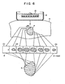
- This 3D image Q is a called wire frame image (see Fig. 6) depicted by wires extending along the outer surface of the 3D image.
- the 3D image Q formed by image processor/ controller 19 is visually displayed by CRT display 20.
- control signal 19a is supplied from image processor/controller 19 to element driver 16.
- driver 16 sets up the element drive conditions for heating tumor P, and drives the transducer elements 13a to 13d of transducer 13 according to the conditions.
- the drive conditions include phase shift conditions for phase shifter 23 to produce ultrasound beams suitable for the shape of tumor P, or the sizes of target P at various depths, and the condition for selection of driven transducer elements by switches 22.
- the conditions further contain the condition for the gain of drive amplifiers 24 to obtain the drive power appropriate for the treatment of tumor P. This drive power is selected to be larger than that in the tomographing mode as mentioned previously.
- the ultrasonic wave transmitted by transducer 13 is a continuous wave.
- ultrasound beams are focused on the position of target P at the depth d, with a pattern dimensionally corresponding to tumor P at the depth d, and this target P is heated for a predetermined period of time.
- ultrasound beams are focused on the position of target P at the incremented depth d + Ad, with a pattern substantially coincide in configuration with tumor target P at this depth.
- the focus points are incremented by Ad, and the tumor target P is irradiated at the corresponding positions with the ultrasound beams patterned to the configurations corresponding to target P at these positions. In this way, target P is effectively and selectively heated.
- transducer 13 is at a standstill.
- ultrasound beams are focused so that they form a small spot at a predetermined depth (this spot may be larger than that for tomographing).
- transducer 13 is driven for heating by scanner 15 to heat intended area at various depths.
- the ultrasound system for hyperthermia treatment can tomograph and heat a target in a patient by a single annular array ultrasound transducer. Therefore, the hyperthermia treatment may be performed accurately but easily.
- annular array ultrasound transducers For example, a plurality of annular array ultrasound transducers, not a single one, are combined and selectively or concurrently driven for tomographing and heating the target.
- Any other appropriate scanning pattern than that shown in Fig. 5 may be used for forming the C-mode image.
- the transducer 13 is fixed for scanning with a fixed focus of ultrasound beams
- the transducer may be. mechanically moved for linear or sector scanning, and with this scanning, the focal point (depth) is varied to obtain a tomogram of a plane containing ultrasound beams, that is, a B-mode image.
- the use of a combination of C- and B-mode images is also involved in this invention.
- the element drive conditions are automatically set up responsive to the control signal 19a from image processor/controller 19. If necessary, an operator may manually set up the conditions while observing the displayed image by display 20.
- pulsative ultrasonic waves in place of the continuous wave of ultrasound may be used for treating.
Abstract
Description
- The present invention relates to an ultrasound therapy system which obtains a tomogram of a biological tissue and effects the treatment of an affected part.
- Recently, various therapy systems using ultrasound, have been developed. One example is hyperthermia treatment, which is one method of treating malignant neoplasm, generally called cancer. Tumors are more sensitive to temperature than healthy tissue. Tumorous tissue dies or does not propagate if it is subjected to a temperature of 42.5°C or more. The treatment based on this phenomenon is called the hyperthermia treatment. Many clinical examples showed that hyperthermia treatment effectively restricts the growth of various types of tumorous tissue and even reduces tumorous tissue.
- Many types of hyperthermia treatment are known. Of these methods, local hyperthermia treatment is particularly effective.
- Local hyperthermia treatment using electromagnetic waves such as microwaves has been proposed and put into practice. This method, however, has one major disadvantage. That is, it is very difficult to accurately heat deep tumors. This is due to the attenuating characteristic of electromagnetic waves with the wave lengths suitable for the hyperthermia treatment (this characteristic depends on the electromagnetic wave length). In this treatment, examples of effective hyperthermia treatment are limited to surfacial tumors located within about 5 centimeters of the epidermis.
- To solve this problem, another method of hyperthermia treatment has been studied and proposed. This method features ultrasonic waves instead of electromagnetic waves. This is because ultrasonic waves can cause vibration.
- Ultrasonic waves are also used to treat calculus such as renal calculus or urinary calculus. In this treatment, high ultrasound beams can be focused on a calculus and effect spallation.
- These approach require one of two types of ultrasound transducers. One type of transducer includes a plurality of ultrasound transducer elements 1 each having a concave spherical ultrasound radiation surface, which are arrayed on a concave spherical surface, as shown in Figs. 1A and 1B. The second transducer is annularly arrayed such that a plurality of ring
shaped transducer elements 2 are concentrically arrayed as shown in Figs. 2A and 2B. Both of the transducers focuses ultrasound waves on a deep target portion P to effect treatment. - The second type of transducer, i.e. an annular array ultrasound transducer, has especially attractive advantages. With this type of transducer, ultrasound beams can be accurately focused on a deep target, and the distance from the transducer to the point of focus can be electrically varied.
- In a conventional system of this type, recognition of the position and configuration of the target to be treated is executed by a diagnostic apparatus for checking and diagnosing a state and location of a specific tissue in a paitent. To treat a tumor, however, another apparatus is required. As a result of using different apparatuses, healthy tissue is frequently treated. Naturally, this is undesirable. In this respect, this method does not permit utilization of the high capacity to focus ultrasound beams, which prevents maximum treatment of diseased tissue. The need for two types of apparatuses also makes treatment complicated and cumbersome. One example is positioning the ultrasonic transducer.
- Accordingly, an object of the present invention is to provide an ultrasound therapy system which can locally and selectively treat only a target portion in a patient by accurately positioning it and recognizing a configuration of it, with an easy operation and good operability.
- To achieve the above object, an ultrasound therapy system comprises an annular array ultrasound transducer constructed with a plurality of ring transducer elements concentrically arrayed, a tomographing processor for driving the transducer by a first drive signal to transmit ultrasonic waves and receiving ultrasound echo waves reflected from internal tissues of a patient, to thereby provide a tomogram of the internal tissues, a treating controller for driving the transducer by a second drive signal to transmit ultrasonic wave for treatment purposes, and a selector for selectively driving the tomographing processor and the treating controller.
- In this system, one annular array ultrasound transducer is used for transmitting and receiving ultrasound to obtain tomograms as well as for transmitting ultrasound for treatment.
- According to this invention, a single ultrasound transducer tomographs a target for observing the target and positioning it, and treats the target only. With this feature, exact positioning and treating the target are secured to provide an effective treatment.
- In the conventional system of this type, different two apparatuses must be used for detecting the tomogram information and treating the specific portion in a patient. Therefore, the transducers of both the apparatuses must be positioned so that ultrasound beams are radiated toward the target portion. The positioning requires some skill for operators.
- This problem was successfully solved by the ultrasound system according to this invention, which uses a single ultrasound transducer. Further, space for system installation is saved and cost to manufacture the system is reduced.
- In the ultrasound therapy system, the treating operation is not performed during the tomographing operation. One might consider that this fact is disadvantageous for diagnosis and treatment work. In practical use, however, there is no need for real time tomographing. The tomographing is only needed when, after positioning and orientation of the transducer, and drive conditions of the transducer are set up while observing the displayed tomogram, other conditions than those as set change.
- This invention can be more fuly understood from the following detailed description when taken in conjunction with the accompanying drawings, in which:
- Figs. 1A and 1B are plan and cross sectional views of a conventional ultrasound transducer using spherical transducer elements in use for hyperthermia treatment, the plan view illustrating an array of spherical transducer elements and the cross sectional view taken on line I - I in Fig. 1A well illustrating the transducer elements in relation with transmitted ultrasound beams;
- Figs. 2A and 2B show plan and cross sectional views of another conventional ultrasound transducer using annular array ultrasound transducer elements in use for ultrasound hyperthermia treatment, the plan view illustrating an array of the transducer elements, and the cross sectional view taken on line II - II in Fig. 2A well illustrating the elements with relation to radiated ultrasound beams;
- Fig. 3 is a block diagram illustrating an arrangement of an ultrasound system for hyperthermia treatment to which the present invention is applied;
- Fig. 4 is a block diagram illustrating a circuit arrangement of an element driver used in the circuit shown in Fig. 3;
- Fig. 5 shows a diagram useful in explaining the scanning by the annular array ultrasound transducer when the system shown in Fig. 3 takes a tomogram; and
- Fig. 6 shows a diagram useful in explaining the operation of the system when it tomographs.
- As shown in Fig. 3, an ultrasound system for hyperthermia treatment according to the present invention is comprised of annular
array ultrasound transducer 13,rod 14,mechanical scanner 15,transducer element driver 16,receiver 17,data acquisition circuit 18, image processor/controller 19, and CRT (cathode ray tube)display 20. -
Transducer 13, like the ultrasound transducer shown in Figs. 2a and 2B, is constructed with a plurality ofring transducer elements 13a to 13d concentrically arrayed.Water bag 13, i.e. a bag containing water, is placed onpatient 11 in contact with his skin. Annulararray ultrasound transducer 13 is disposed in the water inbag 12.Transducer 13 is coupled withmechanical driver 15 by means ofrod 14. For tomographing, thedriver 15 mechanically drivestransducer 13 in a scanning manner. -
Transducer elements 13a to 13d oftransducer 13 are driven by the drive signal derived fromdriver 16, and projects ultrasound beams into the inside ofpatient 11. -
Element driver 16 is comprised ofoscillator 21, a plurality ofswitches 22, a plurality ofphase shifters 23, and a plurality ofdrive amplifiers 24.Oscillator 21, serving as a signal source, is connected throughswitches 22 respectively to the plurality ofphase shifters 23. Each of thesephase shifters 23 delays a signal fromoscillator 21 to phase shift the signal. - These
phase shifters 23 are coupled withdrive amplifiers 24 of a variable gain for amplifying the signals from the phase shifters. The output signals fromamplifiers 24drive elements 13a to 13d. - Echoes of ultrasonic wave coming from the inside of
patient 11 are received byreceiver 17 throughtransducer 13. The echo signals output fromreceiver 17 when it receives echo waves are input todata acquisition circuit 18.Circuit 18 supplies control signal 18a toscanner 15.Circuit 18 further supplies todriver 16control signal 18b containing transducer element drive conditions for tomographying.Data acquisition circuit 18 additionally supplies imaging signal 18c for imaging a C-mode image to image processor/controller 19. Image processor/controller 19 applies todriver 16 control signal 19a containing element drive conditions for heating, and further applies toCRT display 20signal 19b for realizing the three dimensional display or C mode image display.Display image signal 19b is produced by image processor/controller 19 using the signal 18c, derived fromcircuit 18, to form the C-mode image. In a C-mode imaging, only the components of the ultrasound echo signals reflected at a specific depth of an object to be investigated, i.e. the internal tissue ofpatient 11, are collected and arranged according to the locations as reflecting the echo waves, and displayed with varied graduation to give a two dimensional image (C-mode image). - In this example, the combination of
scanner 15,driver 16,receiver 17,data acquisition circuit 18, and image processor/controller 19 takes a tomogram and performs the image formation. Another combination of image processor/controller anddisplay 20 visualizes the tomogram. The heating control of this system is performed through the operation ofdriver 16 in a heating mode, which is controlled by control signal 19a from image processor/controller 19. - The operation of the ultrasound system for hyperthermia treatment as mentioned above will be described in detail referring to Figs. 5 and 6. The system will operate selectively (if necessary, alternatively) in either of two operation modes. In the first mode, an image (C-mode image or a three dimensional (3D) image based on it) of a tumor location and its peripheral is taken and visualized. In the second mode, only the tumor is heated. The ultrasonic wave used in the first mode, or tomogram display mode, is a pulsative wave. The wave in the second mode, or in the heating mode, is a continuous wave.
- In the tomographing mode,
data acquisition circuit 18 sendscontrol signal 18b toelement driver 16. Thecontrol signal 18b is used for setting up element drive conditions (the phase shifts ofphase shifter 23, i.e. delay time and gain of drive amplifiers 24). The conditions contain the condition to focus the ultrasound beams coming fromtransducer 13 at the tumor portion, i.e. the tumor P and its periphery, at the depth d from the skin ofpatient 11. After the element drive conditions are set up,data acquisition circuit 18 supplies control signal 18a tomechanical scanner 15.Scanner 15 responds to control signal 18a to mechanically drivetransducer 13 in a scanning manner byrod 14. This scanning operation may be depicted by dotted line in Fig. 5, for example, and is realized by moving thewhole transducer 13 in a spiral fashion. In connection with such scanning operation oftransducer 13,driver 16 drives theelements 13a to 13d oftransducer 13 in a pulsative fashion with predetermined repetition periods under the above element drive conditions. The elements generate ultrasound beams. - The ultrasound beams projected from
transducer 13 into the interior ofpatient 11 are reflected at the tissue inpatient 11. The reflected beams, i.e. echo beams, are received bytransducer 13 which in turn produces electrical signals representing the received echo beams. The electrical signals are received byreceiver 17. Then, the phases of these signals are aligned with one another indriver 16, amplified and detected.Data acquisition circuit 18 extracts only the signal components reflected at the tissue at the depth d from the output signal ofreceiver 17. Of the echo signals output fromreceiver 17, only the signal components are gated at the timing representing the depth d for extracting these components. - In this way, the information on the C-mode image Cl of the tumor portion at the depth d are obtained.
- Then, the element drive conditions of
driver 16 is modified so that the ultrasound beam is focused on the position at the incremented depth d + Ad. The above operation is then repeated to obtain the information of a C-mode image C2. - Subsequently, similar operations will be repeated while the focusing positions of the ultrasound beams are shifted by td in successive manner. Finally, the information of C mode images Ci (i = 1 to n) in various depths are obtained. The C-mode image signal 18c thus obtained is sent to image processor/
control circuit 19. Thiscircuit 19 forms a three dimensional image Q of the tumor portion on the basis of the C-mode image infor- mation Ci. This 3D image Q, as formed by a conventional technique, is a called wire frame image (see Fig. 6) depicted by wires extending along the outer surface of the 3D image. The 3D image Q formed by image processor/controller 19 is visually displayed byCRT display 20. - The heating operation by this system follows.
- In the heating mode of the system, control signal 19a is supplied from image processor/
controller 19 toelement driver 16. In response to control signal 19a,driver 16 sets up the element drive conditions for heating tumor P, and drives thetransducer elements 13a to 13d oftransducer 13 according to the conditions. The drive conditions include phase shift conditions forphase shifter 23 to produce ultrasound beams suitable for the shape of tumor P, or the sizes of target P at various depths, and the condition for selection of driven transducer elements by switches 22. The conditions further contain the condition for the gain ofdrive amplifiers 24 to obtain the drive power appropriate for the treatment of tumor P. This drive power is selected to be larger than that in the tomographing mode as mentioned previously. In the heating mode, the ultrasonic wave transmitted bytransducer 13 is a continuous wave. - In heating tumor target P, ultrasound beams are focused on the position of target P at the depth d, with a pattern dimensionally corresponding to tumor P at the depth d, and this target P is heated for a predetermined period of time. Following the completion of the heating, ultrasound beams are focused on the position of target P at the incremented depth d + Ad, with a pattern substantially coincide in configuration with tumor target P at this depth. Subsequently, the focus points are incremented by Ad, and the tumor target P is irradiated at the corresponding positions with the ultrasound beams patterned to the configurations corresponding to target P at these positions. In this way, target P is effectively and selectively heated.
- During the heating operation,
scanner 15 stops its scanning operation, and hencetransducer 13 is at a standstill. Alternatively, ultrasound beams are focused so that they form a small spot at a predetermined depth (this spot may be larger than that for tomographing). Under the conditions,transducer 13 is driven for heating byscanner 15 to heat intended area at various depths. - As seen from the foregoing description, the ultrasound system for hyperthermia treatment can tomograph and heat a target in a patient by a single annular array ultrasound transducer. Therefore, the hyperthermia treatment may be performed accurately but easily.
- It is evident that the present invention is not limited to the above specific embodiment, but may be modified within the scope of this invention.
- For example, a plurality of annular array ultrasound transducers, not a single one, are combined and selectively or concurrently driven for tomographing and heating the target.
- Any other appropriate scanning pattern than that shown in Fig. 5 may be used for forming the C-mode image.
- While in the above-mentioned embodiment, the
transducer 13 is fixed for scanning with a fixed focus of ultrasound beams, the transducer may be. mechanically moved for linear or sector scanning, and with this scanning, the focal point (depth) is varied to obtain a tomogram of a plane containing ultrasound beams, that is, a B-mode image. The use of a combination of C- and B-mode images is also involved in this invention. - In the embodiment as mentioned above, the element drive conditions are automatically set up responsive to the control signal 19a from image processor/
controller 19. If necessary, an operator may manually set up the conditions while observing the displayed image bydisplay 20. - Additionally, pulsative ultrasonic waves in place of the continuous wave of ultrasound may be used for treating.
- All of the embodiments have been explained to perform hyperthermia treatment. Needless to say, however, these embodiments can apply to conduct calculus spallation.
Claims (8)
Applications Claiming Priority (2)
| Application Number | Priority Date | Filing Date | Title |
|---|---|---|---|
| JP51717/85 | 1985-03-15 | ||
| JP60051717A JPS61209643A (en) | 1985-03-15 | 1985-03-15 | Ultrasonic diagnostic and medical treatment apparatus |
Publications (3)
| Publication Number | Publication Date |
|---|---|
| EP0194897A2 true EP0194897A2 (en) | 1986-09-17 |
| EP0194897A3 EP0194897A3 (en) | 1987-06-03 |
| EP0194897B1 EP0194897B1 (en) | 1991-03-20 |
Family
ID=12894639
Family Applications (1)
| Application Number | Title | Priority Date | Filing Date |
|---|---|---|---|
| EP86301888A Expired - Lifetime EP0194897B1 (en) | 1985-03-15 | 1986-03-14 | Ultrasound therapy system |
Country Status (4)
| Country | Link |
|---|---|
| US (1) | US4757820A (en) |
| EP (1) | EP0194897B1 (en) |
| JP (1) | JPS61209643A (en) |
| DE (1) | DE3678184D1 (en) |
Cited By (15)
| Publication number | Priority date | Publication date | Assignee | Title |
|---|---|---|---|---|
| EP0221592A2 (en) * | 1985-10-10 | 1987-05-13 | Philips Patentverwaltung GmbH | Method and apparatus for the ultrasonic monitoring of calculus smashing |
| FR2605173A1 (en) * | 1986-10-09 | 1988-04-15 | Wolf Gmbh Richard | ELECTROMAGNETIC TRANSDUCER, ESPECIALLY ACOUSTIC TRANSMITTER FOR MEDICAL PURPOSES |
| DE3743883A1 (en) * | 1986-12-26 | 1988-07-14 | Toshiba Kawasaki Kk | MEDICAL ULTRASONIC TREATMENT DEVICE |
| EP0343432A2 (en) * | 1988-05-25 | 1989-11-29 | Siemens Aktiengesellschaft | Device for the ultrasonic localization of concrements |
| EP0351610A2 (en) * | 1988-07-01 | 1990-01-24 | Hitachi, Ltd. | Ultrasonic apparatus for therapeutical use |
| FR2638532A1 (en) * | 1988-10-27 | 1990-05-04 | Edap Int | ULTRASONIC TREATMENT DEVICE USING A FOCUSING AND OSCILLATING PIEZOELECTRIC CERAMIC |
| US4974587A (en) * | 1988-12-22 | 1990-12-04 | Bsd Medical Corporation | Applicator array and positioning system for hyperthermia |
| EP0419933A1 (en) * | 1989-09-29 | 1991-04-03 | Richard Wolf GmbH | Ultrasonic locating device for a lithotriptor |
| DE4302538C1 (en) * | 1993-01-29 | 1994-04-07 | Siemens Ag | Ultrasonic therapy device for tumour treatment lithotripsy or osteorestoration - with ultrasonic imaging and ultrasonic treatment modes using respective acoustic wave frequencies |
| WO1995001126A1 (en) * | 1993-06-29 | 1995-01-12 | Institute Of Cancer Research: Royal Cancer Hospital | Apparatus for monitoring ultrasonic surgical ablation |
| EP0280088B1 (en) * | 1987-02-16 | 1995-04-26 | Siemens Aktiengesellschaft | Sound generator for treating a living being with focused sound waves |
| US5590653A (en) * | 1993-03-10 | 1997-01-07 | Kabushiki Kaisha Toshiba | Ultrasonic wave medical treatment apparatus suitable for use under guidance of magnetic resonance imaging |
| US5735796A (en) * | 1995-11-23 | 1998-04-07 | Siemens Aktiengesellschaft | Therapy apparatus with a source of acoustic waves |
| CN107847343A (en) * | 2015-07-03 | 2018-03-27 | 拜尔斯道夫股份有限公司 | Heating patch with annular heating unit |
| CN107847342A (en) * | 2015-07-03 | 2018-03-27 | 拜尔斯道夫股份有限公司 | Heating plaster with spiral heating unit |
Families Citing this family (226)
| Publication number | Priority date | Publication date | Assignee | Title |
|---|---|---|---|---|
| US5431621A (en) * | 1984-11-26 | 1995-07-11 | Edap International | Process and device of an anatomic anomaly by means of elastic waves, with tracking of the target and automatic triggering of the shootings |
| US4875487A (en) * | 1986-05-02 | 1989-10-24 | Varian Associates, Inc. | Compressional wave hyperthermia treating method and apparatus |
| US4955366A (en) * | 1987-11-27 | 1990-09-11 | Olympus Optical Co., Ltd. | Ultrasonic therapeutical apparatus |
| US5143063A (en) * | 1988-02-09 | 1992-09-01 | Fellner Donald G | Method of removing adipose tissue from the body |
| US4951653A (en) * | 1988-03-02 | 1990-08-28 | Laboratory Equipment, Corp. | Ultrasound brain lesioning system |
| JPH01250240A (en) * | 1988-03-31 | 1989-10-05 | Toshiba Corp | Calculus crushing apparatus |
| US4938217A (en) * | 1988-06-21 | 1990-07-03 | Massachusetts Institute Of Technology | Electronically-controlled variable focus ultrasound hyperthermia system |
| JP2602923B2 (en) * | 1988-10-31 | 1997-04-23 | 株式会社東芝 | Shock wave therapy device |
| FR2642640B1 (en) * | 1989-02-08 | 1991-05-10 | Centre Nat Rech Scient | METHOD AND DEVICE FOR FOCUSING ULTRASOUND IN TISSUES |
| US5197476A (en) * | 1989-03-16 | 1993-03-30 | Christopher Nowacki | Locating target in human body |
| DE8912723U1 (en) * | 1989-10-27 | 1989-12-28 | Dornier Medizintechnik Gmbh, 8000 Muenchen, De | |
| DE4110102A1 (en) * | 1991-03-27 | 1992-10-01 | Siemens Ag | Electromagnetically driven pressure pulse source for medical use - has electrically conducting membrane formed as annular array of zones activated by drive coils having variable timings |
| EP0514010B1 (en) * | 1991-04-15 | 1996-02-07 | Kabushiki Kaisha Toshiba | Apparatus for destroying a calculus |
| US5233994A (en) * | 1991-05-13 | 1993-08-10 | Advanced Technology Laboratories, Inc. | Detection of tissue abnormality through blood perfusion differentiation |
| FR2685872A1 (en) * | 1992-01-07 | 1993-07-09 | Edap Int | APPARATUS OF EXTRACORPOREAL ULTRASONIC HYPERTHERMIA WITH VERY HIGH POWER AND ITS OPERATING METHOD. |
| US7497828B1 (en) * | 1992-01-10 | 2009-03-03 | Wilk Ultrasound Of Canada, Inc. | Ultrasonic medical device and associated method |
| US5871446A (en) * | 1992-01-10 | 1999-02-16 | Wilk; Peter J. | Ultrasonic medical system and associated method |
| US6023632A (en) * | 1997-07-16 | 2000-02-08 | Wilk; Peter J. | Ultrasonic medical system and associated method |
| JP3325300B2 (en) * | 1992-02-28 | 2002-09-17 | 株式会社東芝 | Ultrasound therapy equipment |
| US5573497A (en) * | 1994-11-30 | 1996-11-12 | Technomed Medical Systems And Institut National | High-intensity ultrasound therapy method and apparatus with controlled cavitation effect and reduced side lobes |
| US5630837A (en) * | 1993-07-01 | 1997-05-20 | Boston Scientific Corporation | Acoustic ablation |
| US5520188A (en) * | 1994-11-02 | 1996-05-28 | Focus Surgery Inc. | Annular array transducer |
| US5558092A (en) * | 1995-06-06 | 1996-09-24 | Imarx Pharmaceutical Corp. | Methods and apparatus for performing diagnostic and therapeutic ultrasound simultaneously |
| US5769879A (en) | 1995-06-07 | 1998-06-23 | Medical Contouring Corporation | Microwave applicator and method of operation |
| US5769790A (en) * | 1996-10-25 | 1998-06-23 | General Electric Company | Focused ultrasound surgery system guided by ultrasound imaging |
| US6319201B1 (en) | 1997-10-15 | 2001-11-20 | Peter J. Wilk | Imaging device and associated method |
| AU748589B2 (en) * | 1997-04-24 | 2002-06-06 | Wilk Patent Development Corporation | Medical imaging device and associated method |
| US6012457A (en) | 1997-07-08 | 2000-01-11 | The Regents Of The University Of California | Device and method for forming a circumferential conduction block in a pulmonary vein |
| US5971983A (en) | 1997-05-09 | 1999-10-26 | The Regents Of The University Of California | Tissue ablation device and method of use |
| US6024740A (en) | 1997-07-08 | 2000-02-15 | The Regents Of The University Of California | Circumferential ablation device assembly |
| US6500174B1 (en) | 1997-07-08 | 2002-12-31 | Atrionix, Inc. | Circumferential ablation device assembly and methods of use and manufacture providing an ablative circumferential band along an expandable member |
| US6869431B2 (en) | 1997-07-08 | 2005-03-22 | Atrionix, Inc. | Medical device with sensor cooperating with expandable member |
| US6997925B2 (en) | 1997-07-08 | 2006-02-14 | Atrionx, Inc. | Tissue ablation device assembly and method for electrically isolating a pulmonary vein ostium from an atrial wall |
| US6652515B1 (en) | 1997-07-08 | 2003-11-25 | Atrionix, Inc. | Tissue ablation device assembly and method for electrically isolating a pulmonary vein ostium from an atrial wall |
| US6966908B2 (en) | 1997-07-08 | 2005-11-22 | Atrionix, Inc. | Tissue ablation device assembly and method for electrically isolating a pulmonary vein ostium from an atrial wall |
| US6117101A (en) | 1997-07-08 | 2000-09-12 | The Regents Of The University Of California | Circumferential ablation device assembly |
| US5947901A (en) | 1997-09-09 | 1999-09-07 | Redano; Richard T. | Method for hemodynamic stimulation and monitoring |
| US6128958A (en) * | 1997-09-11 | 2000-10-10 | The Regents Of The University Of Michigan | Phased array system architecture |
| US6050943A (en) | 1997-10-14 | 2000-04-18 | Guided Therapy Systems, Inc. | Imaging, therapy, and temperature monitoring ultrasonic system |
| US6500121B1 (en) | 1997-10-14 | 2002-12-31 | Guided Therapy Systems, Inc. | Imaging, therapy, and temperature monitoring ultrasonic system |
| US6623430B1 (en) | 1997-10-14 | 2003-09-23 | Guided Therapy Systems, Inc. | Method and apparatus for safety delivering medicants to a region of tissue using imaging, therapy and temperature monitoring ultrasonic system |
| US6071239A (en) * | 1997-10-27 | 2000-06-06 | Cribbs; Robert W. | Method and apparatus for lipolytic therapy using ultrasound energy |
| US6106463A (en) * | 1998-04-20 | 2000-08-22 | Wilk; Peter J. | Medical imaging device and associated method including flexible display |
| US8244370B2 (en) | 2001-04-13 | 2012-08-14 | Greatbatch Ltd. | Band stop filter employing a capacitor and an inductor tank circuit to enhance MRI compatibility of active medical devices |
| US7844319B2 (en) * | 1998-11-04 | 2010-11-30 | Susil Robert C | Systems and methods for magnetic-resonance-guided interventional procedures |
| US6701176B1 (en) | 1998-11-04 | 2004-03-02 | Johns Hopkins University School Of Medicine | Magnetic-resonance-guided imaging, electrophysiology, and ablation |
| US6607502B1 (en) | 1998-11-25 | 2003-08-19 | Atrionix, Inc. | Apparatus and method incorporating an ultrasound transducer onto a delivery member |
| US6139499A (en) * | 1999-02-22 | 2000-10-31 | Wilk; Peter J. | Ultrasonic medical system and associated method |
| EP2259529B1 (en) * | 1999-07-28 | 2019-03-27 | Panasonic Intellectual Property Corporation of America | Apparatus for the transmission and reception of data and method for digital radio communication |
| EP1229839A4 (en) | 1999-10-25 | 2005-12-07 | Therus Corp | Use of focused ultrasound for vascular sealing |
| US6626855B1 (en) | 1999-11-26 | 2003-09-30 | Therus Corpoation | Controlled high efficiency lesion formation using high intensity ultrasound |
| CA2394892A1 (en) * | 1999-12-23 | 2001-06-28 | Therus Corporation | Ultrasound transducers for imaging and therapy |
| US6635017B1 (en) | 2000-02-09 | 2003-10-21 | Spentech, Inc. | Method and apparatus combining diagnostic ultrasound with therapeutic ultrasound to enhance thrombolysis |
| US6517484B1 (en) | 2000-02-28 | 2003-02-11 | Wilk Patent Development Corporation | Ultrasonic imaging system and associated method |
| AU6321301A (en) | 2000-05-16 | 2001-11-26 | Atrionix Inc | Apparatus and method incorporating an ultrasound transducer onto a delivery member |
| ATE290827T1 (en) | 2000-06-13 | 2005-04-15 | Atrionix Inc | SURGICAL ABLATION PROBE FOR FORMING AN ANNUAL LESION |
| US6506171B1 (en) * | 2000-07-27 | 2003-01-14 | Insightec-Txsonics, Ltd | System and methods for controlling distribution of acoustic energy around a focal point using a focused ultrasound system |
| US7914453B2 (en) * | 2000-12-28 | 2011-03-29 | Ardent Sound, Inc. | Visual imaging system for ultrasonic probe |
| US8509913B2 (en) | 2001-04-13 | 2013-08-13 | Greatbatch Ltd. | Switched diverter circuits for minimizing heating of an implanted lead and/or providing EMI protection in a high power electromagnetic field environment |
| US8600519B2 (en) * | 2001-04-13 | 2013-12-03 | Greatbatch Ltd. | Transient voltage/current protection system for electronic circuits associated with implanted leads |
| US8219208B2 (en) | 2001-04-13 | 2012-07-10 | Greatbatch Ltd. | Frequency selective passive component networks for active implantable medical devices utilizing an energy dissipating surface |
| US20070088416A1 (en) | 2001-04-13 | 2007-04-19 | Surgi-Vision, Inc. | Mri compatible medical leads |
| US8977355B2 (en) * | 2001-04-13 | 2015-03-10 | Greatbatch Ltd. | EMI filter employing a capacitor and an inductor tank circuit having optimum component values |
| CA2482202C (en) | 2001-04-13 | 2012-07-03 | Surgi-Vision, Inc. | Systems and methods for magnetic-resonance-guided interventional procedures |
| US8457760B2 (en) | 2001-04-13 | 2013-06-04 | Greatbatch Ltd. | Switched diverter circuits for minimizing heating of an implanted lead and/or providing EMI protection in a high power electromagnetic field environment |
| US8989870B2 (en) | 2001-04-13 | 2015-03-24 | Greatbatch Ltd. | Tuned energy balanced system for minimizing heating and/or to provide EMI protection of implanted leads in a high power electromagnetic field environment |
| US9295828B2 (en) | 2001-04-13 | 2016-03-29 | Greatbatch Ltd. | Self-resonant inductor wound portion of an implantable lead for enhanced MRI compatibility of active implantable medical devices |
| US7211044B2 (en) * | 2001-05-29 | 2007-05-01 | Ethicon Endo-Surgery, Inc. | Method for mapping temperature rise using pulse-echo ultrasound |
| US20030032898A1 (en) | 2001-05-29 | 2003-02-13 | Inder Raj. S. Makin | Method for aiming ultrasound for medical treatment |
| US7846096B2 (en) * | 2001-05-29 | 2010-12-07 | Ethicon Endo-Surgery, Inc. | Method for monitoring of medical treatment using pulse-echo ultrasound |
| AU2003209287A1 (en) * | 2002-01-15 | 2003-07-30 | The Regents Of The University Of California | System and method providing directional ultrasound therapy to skeletal joints |
| US7819826B2 (en) * | 2002-01-23 | 2010-10-26 | The Regents Of The University Of California | Implantable thermal treatment method and apparatus |
| US7285094B2 (en) | 2002-01-30 | 2007-10-23 | Nohara Timothy J | 3D ultrasonic imaging apparatus and method |
| EP1476347B1 (en) * | 2002-02-22 | 2008-02-27 | Bombardier Recreational Products Inc. | A three-wheeled vehicle having a split radiator and an interior storage compartment |
| CA2487140C (en) | 2002-05-29 | 2011-09-20 | Surgi-Vision, Inc. | Magnetic resonance probes |
| US6786202B2 (en) * | 2002-09-24 | 2004-09-07 | Caterpillar Inc | Hydraulic pump circuit |
| US7258690B2 (en) | 2003-03-28 | 2007-08-21 | Relievant Medsystems, Inc. | Windowed thermal ablation probe |
| US6907884B2 (en) | 2002-09-30 | 2005-06-21 | Depay Acromed, Inc. | Method of straddling an intraosseous nerve |
| US8361067B2 (en) | 2002-09-30 | 2013-01-29 | Relievant Medsystems, Inc. | Methods of therapeutically heating a vertebral body to treat back pain |
| US7247141B2 (en) * | 2004-03-08 | 2007-07-24 | Ethicon Endo-Surgery, Inc. | Intra-cavitary ultrasound medical system and method |
| US20050240123A1 (en) * | 2004-04-14 | 2005-10-27 | Mast T D | Ultrasound medical treatment system and method |
| US20050240105A1 (en) * | 2004-04-14 | 2005-10-27 | Mast T D | Method for reducing electronic artifacts in ultrasound imaging |
| US20050240124A1 (en) * | 2004-04-15 | 2005-10-27 | Mast T D | Ultrasound medical treatment system and method |
| US20050234438A1 (en) * | 2004-04-15 | 2005-10-20 | Mast T D | Ultrasound medical treatment system and method |
| US7494467B2 (en) | 2004-04-16 | 2009-02-24 | Ethicon Endo-Surgery, Inc. | Medical system having multiple ultrasound transducers or an ultrasound transducer and an RF electrode |
| US8235909B2 (en) * | 2004-05-12 | 2012-08-07 | Guided Therapy Systems, L.L.C. | Method and system for controlled scanning, imaging and/or therapy |
| US7883468B2 (en) * | 2004-05-18 | 2011-02-08 | Ethicon Endo-Surgery, Inc. | Medical system having an ultrasound source and an acoustic coupling medium |
| US7951095B2 (en) * | 2004-05-20 | 2011-05-31 | Ethicon Endo-Surgery, Inc. | Ultrasound medical system |
| US7473250B2 (en) | 2004-05-21 | 2009-01-06 | Ethicon Endo-Surgery, Inc. | Ultrasound medical system and method |
| US7695436B2 (en) * | 2004-05-21 | 2010-04-13 | Ethicon Endo-Surgery, Inc. | Transmit apodization of an ultrasound transducer array |
| US7806839B2 (en) | 2004-06-14 | 2010-10-05 | Ethicon Endo-Surgery, Inc. | System and method for ultrasound therapy using grating lobes |
| US7914454B2 (en) * | 2004-06-25 | 2011-03-29 | Wilk Ultrasound Of Canada, Inc. | Real-time 3D ultrasonic imaging apparatus and method |
| US9011336B2 (en) * | 2004-09-16 | 2015-04-21 | Guided Therapy Systems, Llc | Method and system for combined energy therapy profile |
| US7393325B2 (en) | 2004-09-16 | 2008-07-01 | Guided Therapy Systems, L.L.C. | Method and system for ultrasound treatment with a multi-directional transducer |
| US7824348B2 (en) | 2004-09-16 | 2010-11-02 | Guided Therapy Systems, L.L.C. | System and method for variable depth ultrasound treatment |
| US8444562B2 (en) | 2004-10-06 | 2013-05-21 | Guided Therapy Systems, Llc | System and method for treating muscle, tendon, ligament and cartilage tissue |
| US8535228B2 (en) | 2004-10-06 | 2013-09-17 | Guided Therapy Systems, Llc | Method and system for noninvasive face lifts and deep tissue tightening |
| US10864385B2 (en) | 2004-09-24 | 2020-12-15 | Guided Therapy Systems, Llc | Rejuvenating skin by heating tissue for cosmetic treatment of the face and body |
| US20130046209A1 (en) | 2011-07-10 | 2013-02-21 | Guided Therapy Systems, Llc | Systems and methods for improving an outside appearance of skin using ultrasound as an energy source |
| US7530958B2 (en) * | 2004-09-24 | 2009-05-12 | Guided Therapy Systems, Inc. | Method and system for combined ultrasound treatment |
| US7530356B2 (en) * | 2004-10-06 | 2009-05-12 | Guided Therapy Systems, Inc. | Method and system for noninvasive mastopexy |
| EP2409730A1 (en) | 2004-10-06 | 2012-01-25 | Guided Therapy Systems, L.L.C. | Method and system for ultrasound tissue treatment |
| US20060111744A1 (en) | 2004-10-13 | 2006-05-25 | Guided Therapy Systems, L.L.C. | Method and system for treatment of sweat glands |
| US8690778B2 (en) * | 2004-10-06 | 2014-04-08 | Guided Therapy Systems, Llc | Energy-based tissue tightening |
| US7758524B2 (en) | 2004-10-06 | 2010-07-20 | Guided Therapy Systems, L.L.C. | Method and system for ultra-high frequency ultrasound treatment |
| US11235179B2 (en) | 2004-10-06 | 2022-02-01 | Guided Therapy Systems, Llc | Energy based skin gland treatment |
| US9827449B2 (en) | 2004-10-06 | 2017-11-28 | Guided Therapy Systems, L.L.C. | Systems for treating skin laxity |
| KR101328103B1 (en) | 2004-10-06 | 2013-11-13 | 가이디드 테라피 시스템스, 엘.엘.씨. | Method and system for noninvasive cosmetic enhancement |
| US11883688B2 (en) | 2004-10-06 | 2024-01-30 | Guided Therapy Systems, Llc | Energy based fat reduction |
| US8133180B2 (en) | 2004-10-06 | 2012-03-13 | Guided Therapy Systems, L.L.C. | Method and system for treating cellulite |
| PT2409731T (en) * | 2004-10-06 | 2017-10-23 | Guided Therapy Systems Llc | System for controlled thermal treatment of human superficial tissue |
| US9694212B2 (en) | 2004-10-06 | 2017-07-04 | Guided Therapy Systems, Llc | Method and system for ultrasound treatment of skin |
| US11724133B2 (en) | 2004-10-07 | 2023-08-15 | Guided Therapy Systems, Llc | Ultrasound probe for treatment of skin |
| US20060079868A1 (en) * | 2004-10-07 | 2006-04-13 | Guided Therapy Systems, L.L.C. | Method and system for treatment of blood vessel disorders |
| US11207548B2 (en) | 2004-10-07 | 2021-12-28 | Guided Therapy Systems, L.L.C. | Ultrasound probe for treating skin laxity |
| US7452357B2 (en) * | 2004-10-22 | 2008-11-18 | Ethicon Endo-Surgery, Inc. | System and method for planning treatment of tissue |
| US7833221B2 (en) | 2004-10-22 | 2010-11-16 | Ethicon Endo-Surgery, Inc. | System and method for treatment of tissue using the tissue as a fiducial |
| US20060089626A1 (en) * | 2004-10-22 | 2006-04-27 | Vlegele James W | Surgical device guide for use with an imaging system |
| JP4695188B2 (en) * | 2005-04-25 | 2011-06-08 | アーデント サウンド, インコーポレイテッド | Method and apparatus for improving the safety of computer peripherals |
| US8932208B2 (en) | 2005-05-26 | 2015-01-13 | Maquet Cardiovascular Llc | Apparatus and methods for performing minimally-invasive surgical procedures |
| US20070083120A1 (en) * | 2005-09-22 | 2007-04-12 | Cain Charles A | Pulsed cavitational ultrasound therapy |
| US10219815B2 (en) | 2005-09-22 | 2019-03-05 | The Regents Of The University Of Michigan | Histotripsy for thrombolysis |
| US8057408B2 (en) * | 2005-09-22 | 2011-11-15 | The Regents Of The University Of Michigan | Pulsed cavitational ultrasound therapy |
| US8167805B2 (en) | 2005-10-20 | 2012-05-01 | Kona Medical, Inc. | Systems and methods for ultrasound applicator station keeping |
| FR2894132B1 (en) * | 2005-12-07 | 2008-06-20 | Stephane Collet | MULTISEQUENTIAL THERAPEUTIC AND HIFU ULTRASONIC MASSAGE SYSTEM (HIGH INTENSITY FOCUSED ULTRASOUND) |
| US20100191306A1 (en) * | 2006-01-25 | 2010-07-29 | Greatbatch Ltd. | Transient voltage suppression circuit for an implanted rfid chip |
| US7769468B2 (en) * | 2006-03-03 | 2010-08-03 | Bsd Medical Corporation | Transparent electromagnetic applicator and hyperthermia treatment method |
| EP3756604A1 (en) | 2006-05-12 | 2020-12-30 | Vytronus, Inc. | Device for ablating body tissue |
| US20100198065A1 (en) * | 2009-01-30 | 2010-08-05 | VyntronUS, Inc. | System and method for ultrasonically sensing and ablating tissue |
| US8903505B2 (en) | 2006-06-08 | 2014-12-02 | Greatbatch Ltd. | Implantable lead bandstop filter employing an inductive coil with parasitic capacitance to enhance MRI compatibility of active medical devices |
| US9566454B2 (en) * | 2006-09-18 | 2017-02-14 | Guided Therapy Systems, Llc | Method and sysem for non-ablative acne treatment and prevention |
| ES2579765T3 (en) * | 2006-09-19 | 2016-08-16 | Guided Therapy Systems, L.L.C. | System for the treatment of muscle, tendon, ligamentous and cartilaginous tissue |
| US9241683B2 (en) * | 2006-10-04 | 2016-01-26 | Ardent Sound Inc. | Ultrasound system and method for imaging and/or measuring displacement of moving tissue and fluid |
| KR100798480B1 (en) * | 2006-11-22 | 2008-01-28 | 한국표준과학연구원 | Apparatus using focused ultrasound wave by controlling electronic signals |
| US8500641B2 (en) * | 2006-11-28 | 2013-08-06 | Koninklijke Philips N.V. | Apparatus and method for 3D ultrasound imaging and therapy |
| US20150174388A1 (en) | 2007-05-07 | 2015-06-25 | Guided Therapy Systems, Llc | Methods and Systems for Ultrasound Assisted Delivery of a Medicant to Tissue |
| DK2152167T3 (en) * | 2007-05-07 | 2018-12-10 | Guided Therapy Systems Llc | Methods and systems for coupling and focusing acoustic energy using a coupling element |
| JP2010526589A (en) | 2007-05-07 | 2010-08-05 | ガイデッド セラピー システムズ, エル.エル.シー. | Method and system for modulating a mediant using acoustic energy |
| EP2209517A4 (en) | 2007-10-05 | 2011-03-30 | Maquet Cardiovascular Llc | Devices and methods for minimally-invasive surgical procedures |
| US10080889B2 (en) | 2009-03-19 | 2018-09-25 | Greatbatch Ltd. | Low inductance and low resistance hermetically sealed filtered feedthrough for an AIMD |
| US9108066B2 (en) | 2008-03-20 | 2015-08-18 | Greatbatch Ltd. | Low impedance oxide resistant grounded capacitor for an AIMD |
| JP5181791B2 (en) * | 2008-04-03 | 2013-04-10 | ソニー株式会社 | Voltage controlled variable frequency oscillation circuit and signal processing circuit |
| CN104545998B (en) | 2008-06-06 | 2020-07-14 | 奥赛拉公司 | System and method for cosmetic treatment and imaging |
| US20100152582A1 (en) * | 2008-06-13 | 2010-06-17 | Vytronus, Inc. | Handheld system and method for delivering energy to tissue |
| US9155588B2 (en) | 2008-06-13 | 2015-10-13 | Vytronus, Inc. | System and method for positioning an elongate member with respect to an anatomical structure |
| WO2009152354A1 (en) * | 2008-06-14 | 2009-12-17 | Vytronus, Inc. | System and method for delivering energy to tissue |
| US10363057B2 (en) | 2008-07-18 | 2019-07-30 | Vytronus, Inc. | System and method for delivering energy to tissue |
| US20100049099A1 (en) * | 2008-07-18 | 2010-02-25 | Vytronus, Inc. | Method and system for positioning an energy source |
| US10028753B2 (en) | 2008-09-26 | 2018-07-24 | Relievant Medsystems, Inc. | Spine treatment kits |
| EP2339972B1 (en) | 2008-09-26 | 2018-04-11 | Relievant Medsystems, Inc. | Systems for navigating an instrument through bone |
| US11298568B2 (en) | 2008-10-30 | 2022-04-12 | Auris Health, Inc. | System and method for energy delivery to tissue while monitoring position, lesion depth, and wall motion |
| US9220924B2 (en) | 2008-10-30 | 2015-12-29 | Vytronus, Inc. | System and method for energy delivery to tissue while monitoring position, lesion depth, and wall motion |
| US9033885B2 (en) * | 2008-10-30 | 2015-05-19 | Vytronus, Inc. | System and method for energy delivery to tissue while monitoring position, lesion depth, and wall motion |
| US8414508B2 (en) | 2008-10-30 | 2013-04-09 | Vytronus, Inc. | System and method for delivery of energy to tissue while compensating for collateral tissue |
| US9192789B2 (en) | 2008-10-30 | 2015-11-24 | Vytronus, Inc. | System and method for anatomical mapping of tissue and planning ablation paths therein |
| US8475379B2 (en) * | 2008-11-17 | 2013-07-02 | Vytronus, Inc. | Systems and methods for ablating body tissue |
| ES2447291T3 (en) | 2008-11-17 | 2014-03-11 | Vytronus, Inc. | System for ablation of body tissue |
| US8447414B2 (en) | 2008-12-17 | 2013-05-21 | Greatbatch Ltd. | Switched safety protection circuit for an AIMD system during exposure to high power electromagnetic fields |
| JP2012513837A (en) | 2008-12-24 | 2012-06-21 | ガイデッド セラピー システムズ, エルエルシー | Method and system for fat loss and / or cellulite treatment |
| US8095224B2 (en) * | 2009-03-19 | 2012-01-10 | Greatbatch Ltd. | EMI shielded conduit assembly for an active implantable medical device |
| US20100312094A1 (en) * | 2009-06-08 | 2010-12-09 | Michael Guttman | Mri-guided surgical systems with preset scan planes |
| CN102625670B (en) | 2009-06-16 | 2015-07-15 | 核磁共振成像介入技术有限公司 | MRI-guided devices and MRI-guided interventional systems that can track and generate dynamic visualizations of the devices in near real time |
| JP5850837B2 (en) | 2009-08-17 | 2016-02-03 | ヒストソニックス,インコーポレーテッド | Disposable acoustic coupling media container |
| EP2470267B1 (en) | 2009-08-26 | 2015-11-11 | The Regents Of The University Of Michigan | Micromanipulator control arm for therapeutic and imaging ultrasound transducers |
| US9901753B2 (en) | 2009-08-26 | 2018-02-27 | The Regents Of The University Of Michigan | Ultrasound lithotripsy and histotripsy for using controlled bubble cloud cavitation in fractionating urinary stones |
| US9177543B2 (en) | 2009-08-26 | 2015-11-03 | Insightec Ltd. | Asymmetric ultrasound phased-array transducer for dynamic beam steering to ablate tissues in MRI |
| US8539813B2 (en) | 2009-09-22 | 2013-09-24 | The Regents Of The University Of Michigan | Gel phantoms for testing cavitational ultrasound (histotripsy) transducers |
| US9174065B2 (en) | 2009-10-12 | 2015-11-03 | Kona Medical, Inc. | Energetic modulation of nerves |
| US20110092880A1 (en) | 2009-10-12 | 2011-04-21 | Michael Gertner | Energetic modulation of nerves |
| US9119951B2 (en) | 2009-10-12 | 2015-09-01 | Kona Medical, Inc. | Energetic modulation of nerves |
| US8469904B2 (en) | 2009-10-12 | 2013-06-25 | Kona Medical, Inc. | Energetic modulation of nerves |
| US20160059044A1 (en) | 2009-10-12 | 2016-03-03 | Kona Medical, Inc. | Energy delivery to intraparenchymal regions of the kidney to treat hypertension |
| US8295912B2 (en) | 2009-10-12 | 2012-10-23 | Kona Medical, Inc. | Method and system to inhibit a function of a nerve traveling with an artery |
| US8986231B2 (en) | 2009-10-12 | 2015-03-24 | Kona Medical, Inc. | Energetic modulation of nerves |
| US8517962B2 (en) | 2009-10-12 | 2013-08-27 | Kona Medical, Inc. | Energetic modulation of nerves |
| US20110118600A1 (en) | 2009-11-16 | 2011-05-19 | Michael Gertner | External Autonomic Modulation |
| US8986211B2 (en) | 2009-10-12 | 2015-03-24 | Kona Medical, Inc. | Energetic modulation of nerves |
| US8661873B2 (en) | 2009-10-14 | 2014-03-04 | Insightec Ltd. | Mapping ultrasound transducers |
| US8715186B2 (en) | 2009-11-24 | 2014-05-06 | Guided Therapy Systems, Llc | Methods and systems for generating thermal bubbles for improved ultrasound imaging and therapy |
| US20110144544A1 (en) * | 2009-12-15 | 2011-06-16 | General Electric Company | Ultrasound transducer assembly and methods of using |
| US8882763B2 (en) | 2010-01-12 | 2014-11-11 | Greatbatch Ltd. | Patient attached bonding strap for energy dissipation from a probe or a catheter during magnetic resonance imaging |
| US9852727B2 (en) | 2010-04-28 | 2017-12-26 | Insightec, Ltd. | Multi-segment ultrasound transducers |
| US9504446B2 (en) | 2010-08-02 | 2016-11-29 | Guided Therapy Systems, Llc | Systems and methods for coupling an ultrasound source to tissue |
| EP2600937B8 (en) | 2010-08-02 | 2024-03-06 | Guided Therapy Systems, L.L.C. | Systems for treating acute and/or chronic injuries in soft tissue |
| US8857438B2 (en) | 2010-11-08 | 2014-10-14 | Ulthera, Inc. | Devices and methods for acoustic shielding |
| JP5373749B2 (en) * | 2010-11-30 | 2013-12-18 | ジーイー・メディカル・システムズ・グローバル・テクノロジー・カンパニー・エルエルシー | Medical image display apparatus and control program thereof |
| JP5605567B2 (en) * | 2010-12-03 | 2014-10-15 | 国立大学法人東北大学 | Array type ultrasonic transmitter |
| US9931514B2 (en) | 2013-06-30 | 2018-04-03 | Greatbatch Ltd. | Low impedance oxide resistant grounded capacitor for an AIMD |
| US10350421B2 (en) | 2013-06-30 | 2019-07-16 | Greatbatch Ltd. | Metallurgically bonded gold pocket pad for grounding an EMI filter to a hermetic terminal for an active implantable medical device |
| US10272252B2 (en) | 2016-11-08 | 2019-04-30 | Greatbatch Ltd. | Hermetic terminal for an AIMD having a composite brazed conductive lead |
| US11198014B2 (en) | 2011-03-01 | 2021-12-14 | Greatbatch Ltd. | Hermetically sealed filtered feedthrough assembly having a capacitor with an oxide resistant electrical connection to an active implantable medical device housing |
| US9427596B2 (en) | 2013-01-16 | 2016-08-30 | Greatbatch Ltd. | Low impedance oxide resistant grounded capacitor for an AIMD |
| US10596369B2 (en) | 2011-03-01 | 2020-03-24 | Greatbatch Ltd. | Low equivalent series resistance RF filter for an active implantable medical device |
| FR2973250B1 (en) * | 2011-03-29 | 2015-01-02 | Edap Tms France | THERAPY PROBE FOR TREATING TISSUE THROUGH CROSS-FOCUSED ULTRASONIC WAVE |
| WO2013012641A1 (en) | 2011-07-11 | 2013-01-24 | Guided Therapy Systems, Llc | Systems and methods for coupling an ultrasound source to tissue |
| US9144694B2 (en) | 2011-08-10 | 2015-09-29 | The Regents Of The University Of Michigan | Lesion generation through bone using histotripsy therapy without aberration correction |
| WO2013101772A1 (en) | 2011-12-30 | 2013-07-04 | Relievant Medsystems, Inc. | Systems and methods for treating back pain |
| US9263663B2 (en) | 2012-04-13 | 2016-02-16 | Ardent Sound, Inc. | Method of making thick film transducer arrays |
| US9049783B2 (en) | 2012-04-13 | 2015-06-02 | Histosonics, Inc. | Systems and methods for obtaining large creepage isolation on printed circuit boards |
| EP2844343B1 (en) | 2012-04-30 | 2018-11-21 | The Regents Of The University Of Michigan | Ultrasound transducer manufacturing using rapid-prototyping method |
| US10588691B2 (en) | 2012-09-12 | 2020-03-17 | Relievant Medsystems, Inc. | Radiofrequency ablation of tissue within a vertebral body |
| US9510802B2 (en) | 2012-09-21 | 2016-12-06 | Guided Therapy Systems, Llc | Reflective ultrasound technology for dermatological treatments |
| WO2014055906A1 (en) | 2012-10-05 | 2014-04-10 | The Regents Of The University Of Michigan | Bubble-induced color doppler feedback during histotripsy |
| EP3598952A3 (en) | 2012-11-05 | 2020-04-15 | Relievant Medsystems, Inc. | Systems and methods for creating curved paths through bone and modulating nerves within the bone |
| USRE46699E1 (en) | 2013-01-16 | 2018-02-06 | Greatbatch Ltd. | Low impedance oxide resistant grounded capacitor for an AIMD |
| CN204017181U (en) | 2013-03-08 | 2014-12-17 | 奥赛拉公司 | Aesthstic imaging and processing system, multifocal processing system and perform the system of aesthetic procedure |
| US10561862B2 (en) | 2013-03-15 | 2020-02-18 | Guided Therapy Systems, Llc | Ultrasound treatment device and methods of use |
| EP4166194A1 (en) | 2013-07-03 | 2023-04-19 | Histosonics, Inc. | Histotripsy excitation sequences optimized for bubble cloud formation using shock scattering |
| US11432900B2 (en) | 2013-07-03 | 2022-09-06 | Histosonics, Inc. | Articulating arm limiter for cavitational ultrasound therapy system |
| US9724151B2 (en) | 2013-08-08 | 2017-08-08 | Relievant Medsystems, Inc. | Modulating nerves within bone using bone fasteners |
| WO2015027164A1 (en) | 2013-08-22 | 2015-02-26 | The Regents Of The University Of Michigan | Histotripsy using very short ultrasound pulses |
| EP3915472A1 (en) | 2014-01-30 | 2021-12-01 | The Board of Trustees of the Leland Stanford Junior University | Device to treat vaginal atrophy |
| SG11201608691YA (en) | 2014-04-18 | 2016-11-29 | Ulthera Inc | Band transducer ultrasound therapy |
| US10925579B2 (en) | 2014-11-05 | 2021-02-23 | Otsuka Medical Devices Co., Ltd. | Systems and methods for real-time tracking of a target tissue using imaging before and during therapy delivery |
| WO2016210133A1 (en) | 2015-06-24 | 2016-12-29 | The Regents Of The Universtiy Of Michigan | Histotripsy therapy systems and methods for the treatment of brain tissue |
| ES2939604T3 (en) | 2016-01-18 | 2023-04-25 | Ulthera Inc | Compact ultrasonic device having an annular ultrasonic array peripherally electrically connected to a flexible printed circuit board |
| US11241218B2 (en) | 2016-08-16 | 2022-02-08 | Ulthera, Inc. | Systems and methods for cosmetic ultrasound treatment of skin |
| JP2019534752A (en) * | 2016-10-04 | 2019-12-05 | オークタ テクノロジーズ インコーポレイテッドAucta Technologies Inc. | Apparatus and method for selectively activating afferent nerve fibers |
| US10249415B2 (en) | 2017-01-06 | 2019-04-02 | Greatbatch Ltd. | Process for manufacturing a leadless feedthrough for an active implantable medical device |
| US11944849B2 (en) | 2018-02-20 | 2024-04-02 | Ulthera, Inc. | Systems and methods for combined cosmetic treatment of cellulite with ultrasound |
| US10905888B2 (en) | 2018-03-22 | 2021-02-02 | Greatbatch Ltd. | Electrical connection for an AIMD EMI filter utilizing an anisotropic conductive layer |
| US10912945B2 (en) | 2018-03-22 | 2021-02-09 | Greatbatch Ltd. | Hermetic terminal for an active implantable medical device having a feedthrough capacitor partially overhanging a ferrule for high effective capacitance area |
| EP3886737A4 (en) | 2018-11-28 | 2022-08-24 | Histosonics, Inc. | Histotripsy systems and methods |
| USD897543S1 (en) | 2019-03-01 | 2020-09-29 | Madorra Inc. | Disposable component for vaginal ultrasound therapy device |
| CA3150339A1 (en) | 2019-09-12 | 2021-03-18 | Brian W. Donovan | Systems and methods for tissue modulation |
| AU2021213168A1 (en) | 2020-01-28 | 2022-09-01 | The Regents Of The University Of Michigan | Systems and methods for histotripsy immunosensitization |
Citations (6)
| Publication number | Priority date | Publication date | Assignee | Title |
|---|---|---|---|---|
| US3051167A (en) * | 1957-07-23 | 1962-08-28 | Univ Illinois | Timing and sequence control circuitry |
| US3237623A (en) * | 1963-02-04 | 1966-03-01 | George A D Gordon | Apparatus for destroying limited groups of cells |
| US4246784A (en) * | 1979-06-01 | 1981-01-27 | Theodore Bowen | Passive remote temperature sensor system |
| DE3119295A1 (en) * | 1981-05-14 | 1982-12-16 | Siemens AG, 1000 Berlin und 8000 München | DEVICE FOR DESTROYING CONCRETE IN BODIES |
| EP0068961A2 (en) * | 1981-06-26 | 1983-01-05 | Thomson-Csf | Apparatus for the local heating of biological tissue |
| US4390025A (en) * | 1980-04-24 | 1983-06-28 | Tokyo Shibaura Denki Kabushiki Kaisha | Ultrasonic display apparatus having means for detecting the position of an ultrasonic probe |
Family Cites Families (9)
| Publication number | Priority date | Publication date | Assignee | Title |
|---|---|---|---|---|
| JPS5124092A (en) * | 1974-08-21 | 1976-02-26 | Tokyo Shibaura Electric Co | |
| US3958559A (en) * | 1974-10-16 | 1976-05-25 | New York Institute Of Technology | Ultrasonic transducer |
| JPS5468090A (en) * | 1977-11-10 | 1979-05-31 | Tokyo Shibaura Electric Co | Ultrasonic scanner |
| DE2908424C2 (en) * | 1978-05-08 | 1980-12-18 | Dr.-Ing. J.F. Toennies Erben Kg, 7800 Freiburg | Method and arrangement for the representation of electrical space curves |
| US4315514A (en) * | 1980-05-08 | 1982-02-16 | William Drewes | Method and apparatus for selective cell destruction |
| US4484569A (en) * | 1981-03-13 | 1984-11-27 | Riverside Research Institute | Ultrasonic diagnostic and therapeutic transducer assembly and method for using |
| FR2556582B1 (en) * | 1983-12-14 | 1986-12-19 | Dory Jacques | ULTRASONIC PULSE APPARATUS FOR DESTROYING CALCULATIONS |
| US4620546A (en) * | 1984-06-30 | 1986-11-04 | Kabushiki Kaisha Toshiba | Ultrasound hyperthermia apparatus |
| US4620545A (en) * | 1984-10-31 | 1986-11-04 | Trutek Research, Inc. | Non-invasive destruction of kidney stones |
-
1985
- 1985-03-15 JP JP60051717A patent/JPS61209643A/en active Pending
-
1986
- 1986-03-12 US US06/838,953 patent/US4757820A/en not_active Expired - Lifetime
- 1986-03-14 EP EP86301888A patent/EP0194897B1/en not_active Expired - Lifetime
- 1986-03-14 DE DE8686301888T patent/DE3678184D1/en not_active Expired - Lifetime
Patent Citations (6)
| Publication number | Priority date | Publication date | Assignee | Title |
|---|---|---|---|---|
| US3051167A (en) * | 1957-07-23 | 1962-08-28 | Univ Illinois | Timing and sequence control circuitry |
| US3237623A (en) * | 1963-02-04 | 1966-03-01 | George A D Gordon | Apparatus for destroying limited groups of cells |
| US4246784A (en) * | 1979-06-01 | 1981-01-27 | Theodore Bowen | Passive remote temperature sensor system |
| US4390025A (en) * | 1980-04-24 | 1983-06-28 | Tokyo Shibaura Denki Kabushiki Kaisha | Ultrasonic display apparatus having means for detecting the position of an ultrasonic probe |
| DE3119295A1 (en) * | 1981-05-14 | 1982-12-16 | Siemens AG, 1000 Berlin und 8000 München | DEVICE FOR DESTROYING CONCRETE IN BODIES |
| EP0068961A2 (en) * | 1981-06-26 | 1983-01-05 | Thomson-Csf | Apparatus for the local heating of biological tissue |
Non-Patent Citations (1)
| Title |
|---|
| IEEE TRANSACTIONS ON BIOMEDICAL ENGINEERING, Vol. BME-31, no. 1, January 1984, pages 136-149, IEEE, New York, US; J.W. STROHBEHN et al.: "A survey of computer simulations of hyperthermia treatments" * |
Cited By (24)
| Publication number | Priority date | Publication date | Assignee | Title |
|---|---|---|---|---|
| EP0221592A2 (en) * | 1985-10-10 | 1987-05-13 | Philips Patentverwaltung GmbH | Method and apparatus for the ultrasonic monitoring of calculus smashing |
| EP0221592A3 (en) * | 1985-10-10 | 1987-05-20 | Philips Patentverwaltung Gmbh | Method and apparatus for the ultrasonic monitoring of calculus smashing |
| FR2605173A1 (en) * | 1986-10-09 | 1988-04-15 | Wolf Gmbh Richard | ELECTROMAGNETIC TRANSDUCER, ESPECIALLY ACOUSTIC TRANSMITTER FOR MEDICAL PURPOSES |
| DE3743883A1 (en) * | 1986-12-26 | 1988-07-14 | Toshiba Kawasaki Kk | MEDICAL ULTRASONIC TREATMENT DEVICE |
| DE3743883C3 (en) * | 1986-12-26 | 1998-08-13 | Toshiba Kawasaki Kk | Medical ultrasound treatment device |
| EP0280088B1 (en) * | 1987-02-16 | 1995-04-26 | Siemens Aktiengesellschaft | Sound generator for treating a living being with focused sound waves |
| EP0343432A2 (en) * | 1988-05-25 | 1989-11-29 | Siemens Aktiengesellschaft | Device for the ultrasonic localization of concrements |
| EP0343432A3 (en) * | 1988-05-25 | 1990-01-17 | Siemens Aktiengesellschaft | Device for the ultrasonic localization of concrements |
| EP0538241A2 (en) * | 1988-07-01 | 1993-04-21 | Hitachi, Ltd. | Ultrasonic apparatus for therapeutical use |
| EP0538241B1 (en) * | 1988-07-01 | 1998-02-04 | Hitachi, Ltd. | Ultrasonic apparatus for therapeutical use |
| EP0351610A2 (en) * | 1988-07-01 | 1990-01-24 | Hitachi, Ltd. | Ultrasonic apparatus for therapeutical use |
| EP0351610A3 (en) * | 1988-07-01 | 1990-05-23 | Hitachi, Ltd. | Ultrasonic apparatus for therapeutical use |
| FR2638532A1 (en) * | 1988-10-27 | 1990-05-04 | Edap Int | ULTRASONIC TREATMENT DEVICE USING A FOCUSING AND OSCILLATING PIEZOELECTRIC CERAMIC |
| EP0370841A1 (en) * | 1988-10-27 | 1990-05-30 | Edap International | Ultrasound treatment apparatus using a focalizing and oscillating piezoelectric ceramic device |
| US4974587A (en) * | 1988-12-22 | 1990-12-04 | Bsd Medical Corporation | Applicator array and positioning system for hyperthermia |
| EP0419933A1 (en) * | 1989-09-29 | 1991-04-03 | Richard Wolf GmbH | Ultrasonic locating device for a lithotriptor |
| DE4302538C1 (en) * | 1993-01-29 | 1994-04-07 | Siemens Ag | Ultrasonic therapy device for tumour treatment lithotripsy or osteorestoration - with ultrasonic imaging and ultrasonic treatment modes using respective acoustic wave frequencies |
| US5526815A (en) * | 1993-01-29 | 1996-06-18 | Siemens Aktiengesellschat | Therapy apparatus for locating and treating a zone located in the body of a life form with acoustic waves |
| US5590653A (en) * | 1993-03-10 | 1997-01-07 | Kabushiki Kaisha Toshiba | Ultrasonic wave medical treatment apparatus suitable for use under guidance of magnetic resonance imaging |
| US5897495A (en) * | 1993-03-10 | 1999-04-27 | Kabushiki Kaisha Toshiba | Ultrasonic wave medical treatment apparatus suitable for use under guidance of magnetic resonance imaging |
| WO1995001126A1 (en) * | 1993-06-29 | 1995-01-12 | Institute Of Cancer Research: Royal Cancer Hospital | Apparatus for monitoring ultrasonic surgical ablation |
| US5735796A (en) * | 1995-11-23 | 1998-04-07 | Siemens Aktiengesellschaft | Therapy apparatus with a source of acoustic waves |
| CN107847343A (en) * | 2015-07-03 | 2018-03-27 | 拜尔斯道夫股份有限公司 | Heating patch with annular heating unit |
| CN107847342A (en) * | 2015-07-03 | 2018-03-27 | 拜尔斯道夫股份有限公司 | Heating plaster with spiral heating unit |
Also Published As
| Publication number | Publication date |
|---|---|
| US4757820A (en) | 1988-07-19 |
| EP0194897B1 (en) | 1991-03-20 |
| JPS61209643A (en) | 1986-09-17 |
| EP0194897A3 (en) | 1987-06-03 |
| DE3678184D1 (en) | 1991-04-25 |
Similar Documents
| Publication | Publication Date | Title |
|---|---|---|
| US4757820A (en) | Ultrasound therapy system | |
| US5520188A (en) | Annular array transducer | |
| US5769790A (en) | Focused ultrasound surgery system guided by ultrasound imaging | |
| US5065740A (en) | Ultrasonic medical treatment apparatus | |
| US6361500B1 (en) | Three transducer catheter | |
| US5080102A (en) | Examining, localizing and treatment with ultrasound | |
| US5435311A (en) | Ultrasound therapeutic system | |
| US4787394A (en) | Ultrasound therapy apparatus | |
| US20040068186A1 (en) | Ultrasonic therapeutic probe and ultrasonic device | |
| EP0170416A1 (en) | Ultrasound hyperthermia apparatus | |
| US20040162507A1 (en) | Externally-applied high intensity focused ultrasound (HIFU) for therapeutic treatment | |
| JPH0889525A (en) | Method and equipment for monitoring the physique of patient during ultrasonic wave medical treatment | |
| JP2000126185A (en) | Ultrasonic apparatus for treatment | |
| KR102111453B1 (en) | Apparatus for Extracorporeal Shock Wave Therapy | |
| JP2001046387A (en) | Ultrasonic therapeutic applicator | |
| JPH1033535A (en) | Doppler ultrasonograph and its method | |
| JP4434668B2 (en) | Treatment system and treatment support system | |
| JP4319427B2 (en) | Medical ultrasonic irradiation equipment | |
| JPH09135908A (en) | Ultrasonic diagnosis treatment system | |
| US10974073B2 (en) | Ultrasonic image guidance of radiation therapy procedures | |
| JPH0331456B2 (en) | ||
| CN111494817A (en) | Large focal region forming system of HIFU device and focal region forming method thereof | |
| WO1999040847A2 (en) | Multi-frequency ultrasonic imaging and therapy | |
| JP2937344B2 (en) | Ultrasound therapy equipment | |
| JPH0824268A (en) | Impulse wave treating apparatus and thermal treating apparatus |
Legal Events
| Date | Code | Title | Description |
|---|---|---|---|
| PUAI | Public reference made under article 153(3) epc to a published international application that has entered the european phase |
Free format text: ORIGINAL CODE: 0009012 |
|
| AK | Designated contracting states |
Kind code of ref document: A2 Designated state(s): DE FR NL |
|
| 17P | Request for examination filed |
Effective date: 19861031 |
|
| PUAL | Search report despatched |
Free format text: ORIGINAL CODE: 0009013 |
|
| AK | Designated contracting states |
Kind code of ref document: A3 Designated state(s): DE FR NL |
|
| 17Q | First examination report despatched |
Effective date: 19890714 |
|
| GRAA | (expected) grant |
Free format text: ORIGINAL CODE: 0009210 |
|
| AK | Designated contracting states |
Kind code of ref document: B1 Designated state(s): DE FR NL |
|
| PG25 | Lapsed in a contracting state [announced via postgrant information from national office to epo] |
Ref country code: NL Effective date: 19910320 |
|
| REF | Corresponds to: |
Ref document number: 3678184 Country of ref document: DE Date of ref document: 19910425 |
|
| ET | Fr: translation filed | ||
| NLV1 | Nl: lapsed or annulled due to failure to fulfill the requirements of art. 29p and 29m of the patents act | ||
| PLBI | Opposition filed |
Free format text: ORIGINAL CODE: 0009260 |
|
| 26 | Opposition filed |
Opponent name: SIEMENS AG GRPA 4 ERL S Effective date: 19911218 |
|
| PGFP | Annual fee paid to national office [announced via postgrant information from national office to epo] |
Ref country code: FR Payment date: 19930309 Year of fee payment: 8 |
|
| PGFP | Annual fee paid to national office [announced via postgrant information from national office to epo] |
Ref country code: DE Payment date: 19930319 Year of fee payment: 8 |
|
| RDAG | Patent revoked |
Free format text: ORIGINAL CODE: 0009271 |
|
| STAA | Information on the status of an ep patent application or granted ep patent |
Free format text: STATUS: PATENT REVOKED |
|
| 27W | Patent revoked |
Effective date: 19930504 |