EP0201084B1 - A local probe for use in nmr imaging - Google Patents
A local probe for use in nmr imaging Download PDFInfo
- Publication number
- EP0201084B1 EP0201084B1 EP86106199A EP86106199A EP0201084B1 EP 0201084 B1 EP0201084 B1 EP 0201084B1 EP 86106199 A EP86106199 A EP 86106199A EP 86106199 A EP86106199 A EP 86106199A EP 0201084 B1 EP0201084 B1 EP 0201084B1
- Authority
- EP
- European Patent Office
- Prior art keywords
- loop
- gap
- resonator
- resonators
- pair
- Prior art date
- Legal status (The legal status is an assumption and is not a legal conclusion. Google has not performed a legal analysis and makes no representation as to the accuracy of the status listed.)
- Expired - Lifetime
Links
Images

Classifications
-
- G—PHYSICS
- G01—MEASURING; TESTING
- G01R—MEASURING ELECTRIC VARIABLES; MEASURING MAGNETIC VARIABLES
- G01R33/00—Arrangements or instruments for measuring magnetic variables
- G01R33/20—Arrangements or instruments for measuring magnetic variables involving magnetic resonance
- G01R33/28—Details of apparatus provided for in groups G01R33/44 - G01R33/64
- G01R33/32—Excitation or detection systems, e.g. using radio frequency signals
- G01R33/34—Constructional details, e.g. resonators, specially adapted to MR
- G01R33/343—Constructional details, e.g. resonators, specially adapted to MR of slotted-tube or loop-gap type
Definitions
- the field of the invention is gyromagnetic resonance spectroscopy, and particularly, nuclear magnetic resonance (NMR) techniques for measuring the properties of materials.
- NMR nuclear magnetic resonance
- Gyromagnetic resonance spectroscopy is conducted to study nuclei that have magnetic -moments and electrons which are in a paramagnetic state.
- the former is referred to in the art as nuclear magnetic resonsance (NMR), and the latter is referred to as paramagnetic resonance (EPR) or electron spin resonance (ESR).
- NMR nuclear magnetic resonsance
- EPR paramagnetic resonance
- ESR electron spin resonance
- any nucleus which possesses a magnetic moment attempts to align itself with the direction of the magnetic field in which it is located. In doing so, however, the nucleus precesses around this direction at a characteristic angular frequency (Larmor frequency) which is dependent on the strength of the magnetic field and on the properties of the specific nuclear species (the magnetogyric constant of the nucleus).
- Larmor frequency characteristic angular frequency which is dependent on the strength of the magnetic field and on the properties of the specific nuclear species (the magnetogyric constant of the nucleus).
- polarizing field B z When a substance such as human tissue is subjected to a uniform magnetic field (polarizing field B z ) the individual magnetic moments of the paramagnetic nuclei in the tissue attempt to align with this field, but precess about it in random order at their characteristic Larmor frequency. A net magnetic moment M z is produced in the direction of the polarizing field, but the randomly oriented components in the perpendicular plane (x-y plane) cancel one another.
- the decay constant 1/T 2 is a characteristic of the process and it provides valuable information about the substance under study.
- the time constant T 2 is referred to as the "spin-spin relaxation” constant, or the “transverse relaxation” constant, and it measures the rate at which the aligned precession of the nuclei dephase after removal of the excitation signal B 1 .
- T 2 spin-spin relaxation process which is characterized by the time constant T,.
- T This is also called the longitudinal relaxation process as it describes the recovery of the net magnetic moment M to its equilibrium value M o along the axis of magnetic polarization (Z).
- the T 1 time constant is longer than T 2 , much longer in most substances, and its independent measurement is the subject of many gyromagnetic procedures.
- NMR measurements are useful in many scientific and engineering fields, their potential use in the field of medicine is enormous. NMR measurements provide a contrast mechanism which is quite different from x-rays, and this enables differences between soft tissues to be observed with NMR which are completely indiscernible with x-rays. In addition, physiological differences can be observed with NMR measurements, whereas x-rays are limited primarily to anatomical studies.
- zeugmatography For most medical applications utilizing NMR, an imaging technique must be employed to obtain gyromagnetic information at specific locations in the subject.
- the foremost NMR imaging technique is referred to as “zeugmatography” and was first proposed by P. C. Lauterbur in a publication "Image Formation by Induced Local Interactions: Examples Employing Nuclear Magnetic Resonance", Nature, Vol. 242, Mar. 16, 1973, pp. 190-191.
- the NMR signal is “tagged”, or “sensitized”, with position information.
- position sensitizing of the NMR signal enables an NMR image to be produced by a series of measurements.
- NMR imaging methods have been classified as point methods, line methods, plane methods and three dimensional methods. These are discussed, for example, by P. Mansfield and P. G. Morris in their book “NMR Imaging in Biomedicine” published in 1982 by Academic Press, New York.
- the NMR scanners which implement these techniques are constructed in a variety of sizes. Small, specially designed machines, are employed to examine laboratory animals or to provide images of specific parts of the human body. On the other hand, "whole body” NMR scanners are sufficiently large to receive an entire human body and produce an image of any portion thereof.
- a large coil which has both a uniform and high sensitivity to the FID signal produced in a while body NMR scanner.
- another commonly used technique is to employ "local" coils to either generate the excitation signal (B,), receive the resulting FID signal, or both generate and receive.
- Such local coils are relatively small and are constructed to produce the desired field or receive the FID signal from a localized portion of the patient.
- different local coils may be employed for imaging the head and neck, legs and arms, or various internal organs.
- the local coil should be designed to provide a relatively uniform sensitivity to the FID signals produced by the precessing nuclei throughout the region of interest.
- loop-gap novel resonator structure
- the loop-gap resonator may take a wide variety of shapes.
- a lumped circuit resonator is formed in which a conductive loop is the inductive element and one or more gaps are formed in this loop to form a capacitive element.
- loop-gap resonator While the loop-gap resonator has many desirable characteristics normally associated with lumped circuit resonators, it also has some characteristics normally associated with cavity resonators. Most notable of these is the much higher qualify factor, or "Q", of the loop-gap resonator over the traditional lumped circuit resonators. When applied to NMR scanners, this higher Q translates into higher resolution images.
- the present invention relates to a local probe for use in NMR imaging of selected portions of a patient, and particularly, to a local probe which employs loop-gap resonators that enhance the quality of the resulting images. More specifically, the present invention includes a pair of loop-gap resonators which are positioned adjacent to one another, and in which a capacitive element in each loop-gap resonator is electrically connected to the capacitive element in the other loop-gap resonator to link the two loop-gap resonators and to thereby define a region of relatively uniform sensitivity therebetween.
- a general object of the invention is to provide a local probe which may be employed to image many different regions of the human anatomy. This. is accomplished in part by mounting the two loop-gap resonators to a support arm which may be adjusted in length to alter the lateral spacing between the loop-gap resonators.
- the loop-gap resonators may also be rotatably connected to the support arm such that they can be aligned along a common axis to form an axial pair, or they can be rotated through a range of orientations to form a planar pair in which their respective axes are substantially perpendicular to the common axis.
- Another object of the invention is to provide a probe which is sensitive to the FID signals produced in the region of interest, but is relatively insensitive to the excitation signal produced by a separate coil.
- the loop-gap resonators When the loop-gap resonators are rotated to form a planar pair, they are insensitive to excitation fields which are perpendicular to their axes. If the loop-gap resonators are also substantially physically identical such that there is geometric symmetry about a plane therebetween, the probe is also insensitive to excitation fields parallel to the axes of the loop-gap resonators. This is particularly advantageous when circularly polarized excitation fields are separately produced, since such fields have components parallel to and perpendicular to the loop-gap resonator axes,
- a more specific object of the present invention is to provide a probe which need not be "returned” for each patient. This is accomplished in, part by providing multiple gaps in each loop-gap resonator to reduce the potentials there- across and reduce the intensity of the resulting electric fields.- This effect is further enhanced by increasing the lengthwise dimension (Z) of each loop-gap resonator.
- Yet another object of the invention is to provide a probe which is sensitive to FID signals produced at different frequencies.
- Each loop-gap resonator pair resonates in two modes.
- the resonant frequency of each of these modes can be fixed by the geometry of the loops, the spacing between the loops and the geometry of their gaps.
- One frequency may be set, for example, to detect the FID signal produced by hydrogen nuclei, and the second frequency may be set to detect phosphorous or sodium nuclei.
- the loop-gap resonator 1 which is employed in the present invention is a lumped circuit resonator which resonates at a radio frequency determined by its geometry.
- the lumped circuit resonator 1 has dimensions which are much less than the wavelength of the radio frequency signal at which it resonates.
- the capacitive and inductive elements are identifiable and the electromagnetic field oscillates between a magnetic field generated by the inductive element and an electric field generated by the capacitive element.
- the inductive element in the resonator 1 is the loop, or ring, formed by two metallic pieces 2 and 3, and the capacitive element is the longitudinal gaps 4 and 5 formed at the juncture of the two pieces 2 and 3.
- the magnetic field produced by the resonator 1 is concentrated along a central axis 6, and the electric field is concentrated in the gaps 4 and 5.
- the magnetic flux flows through the opening defined by the loop and curves radially outward at each of its ends and along the outside of the loop to form a close flux path.
- the resonant frequency of the resonator 1 is determined primarily by its geometry, and it can be constructed to operate over a wide range of frequencies of interest in gyromagnetic spectroscopy. Where the spacing (t) in the gaps 4 and 5 is much smaller than their width (w), the resonant frequency of a loop-gap resonator is as follows: where:
- the length (Z) has virtually no effect on the resonant frequency.
- one or more gaps may be employed and these need not be of equal dimensions or provide equal capacitance.
- the loop need not be circular, although there are often advantages to a circular construction as will be described in more detail below.
- energy may be applied or removed from the loop-gap resonator in either of two ways. Energy may be inductively coupled to or from the resonator by a conductive loop which encircles magnetic flux flowing through the loops and which connects to the end of a transmission line. Alternatively, energy can be capacitively coupled to or from the resonator by connecting the transmission line to the plates of one of the resonator's capacitive elements through an impedance matching network.
- the present invention employs two loop-gap resonators 10 and 11 which are spaced from one another to define a region 12 therebetween for receiving a material to be examined.
- the loop-gap resonators 10 and 11 When placed next to each other in this manner, the loop-gap resonators 10 and 11 will resonate in two modes.
- the first mode referred to herein as the "unlinked” mode, is indicated by the dashed lines 13 and 14 which represent the paths of the magnetic flux flowing through each loop-gap resonator 10 and 11 in the opposite directions.
- the second resonant mode referred to herein as the "linked” mode, is indicated by the dashed lines 17 which represent the paths of the magnetic flux flowing through each resonator 10 and 11 in the same direction.
- the unlinked resonant mode is suppressed and the fields indicated by dashed lines 13 and 14 are not produced.
- the resonator pair operate in their linked resonant mode to produce a relatively uniform sensitivity in the region 12. While the electrical connection can be made in a number of ways, in the preferred embodiment a pair of flexible, insulated wires 18 are employed for this purpose.
- the loop-gap resonators 30 and 31 in a second embodiment of the invention are aligned side-by-side to provide a "planar pair" which produces a region of relatively uniform sensitivity at 32.
- a pair of plates 33 and 34 connect between corresponding surfaces of the gaps 35 and 36 to suppress their unilnked mode of operation and produce a relatively uniform magnetic field in the region 32 as indicated by dashed lines 37.
- the central axes 38 and 39 of the respective loop-gap resonators 30 and 31 are not coaxial, but are substantially parallel to each other.
- the connecting plates 33 and 34 may be rigid, and may provide additional capacitance which contributes to the determination of the resonant frequency of the linked pair as indicated by the above equation.
- each loop-gap resonator 30 and 31 includes a second gap 40 and 41 respectively, which also contributes to the resonant frequency of the linked pair.
- the sensitivity of the local probe to changes in the dielectric properties of the subject being examined can be reduced.
- the necessity of retuning the local probe to the desired resonant frequency when the probe is moved to different regions of the anatomy or is applied to different patients is substantially reduced.
- each of these gaps has a capacitance of n x C, where C is the total capacitance of the loop-gap resonator.
- the energy stored in each gap is (n x C)(V') 2 and the total energy is n x (n x C)(V') 2 lf a single gap were used, the total energy would be CV 2 , and since these energies must be equal, then:
- the use of n gaps thus reduces the potentials across each gap by a factor of n. This reduces the electric fields, and in turn, reduces the sensitivity to changes in the dielectric properties of the subject being examined.
- a pair of loop-gap resonators 50 and 51 are formed on a molded plastic supporting structure 52 and are oriented to form an axial pair.
- the supporting structure 52 is formed as two separate sections 52a and 52b, with each section having a circular cylindrical tube 53a and 53b and an attached arm 54a and 54b. They are molded from polyvinyl chloride.
- the arm 54a telescopes within the arm 54b and a fastener 55 extends through the arms 54a and 54b to hold them together.
- a pair of slots 56 and 57 are formed in the arm 54a, and by loosening the fastener 55, the length of the arms 54a and 54b can be adjusted to after the axial spacing between the loop-gap resonators 50 and 51.
- the gaps -58 and. 59 on the respective loop-gap resonators 50 and 51 are connected together as described above to provide a region of relatively uniform sensitivity 60 therebetween.
- These connections are made by two pieces of 300 ohm antenna wire 61 and 62 which are equal in length and are joined at a variable capacitor 63 that is mounted in the wall of the arm 54b.
- the resonant frequency of the axial pair 50 and 51 can be precisely tuned to the frequency of the FID signal emanating from a subject 64 disposed in the region 60.
- An electrical signal is produced across the plates of the capacitor 63 by the FID signal, and this electrical signal may be coupled to the inputs of a receiver.
- This construction is particularly well suited for examining the arms and legs of a patient, as well as portions of the torso.
- the local probe when used to receive the FID signals, a separate coil is employed to produce the excitation field B,.
- the component of the excitation field Bi in the direction indicated by an x axis 65 will not induce a voltage in the loop-gap resonators 50 or 51.
- the component in the direction indicated by a Y axis 66 will couple with the loop-gap resonators 50 and 51, and will produce a large signal which is applied to the inputs of the attached receiver.
- a second, substantially identical loop-gap resonator 67 and 68 is formed adjacent to the respective loop-gap resonators 50 and 51.
- the structurre of Fig. 4a has four resonant modes.
- the mode of Fig. 5a is the desired mode, with the flux lines 73 linking the loop-gap resonators 50 and 51, and with equal but opposite flux lines passing through the separate, unlinked loop-gap resonators 67 and 68.
- the modes of Figs. 5b and 5c are suppressed with the connections provided by wires 61 and 62 to the loop-gap resonators 50 and 51.
- this fourth mode can also be suppressed by electrical cross connections 71 which are made between corresponding gaps 69 and 58 in the resonator pair 67 and 50, and electrical cross connections 72 which are made between corresponding gaps 59 and 70 in the resonator pair 51 and 68.
- electrical cross connections 71 which are made between corresponding gaps 69 and 58 in the resonator pair 67 and 50
- electrical cross connections 72 which are made between corresponding gaps 59 and 70 in the resonator pair 51 and 68.
- an FID signal emanating from the region 60 will induce a signal in the axial pair 50 and 51, but a substantially uniform excitation field B, passing through all four loop-gap resonators 67,50,51 and 68 will not.
- the local probe may be substantially isolated from the excitation field B 1 .
- each loop-gap resonator 67, 50, 51 and 68 has a radius (r) of 10.2 cm (4 inches), an axial length (Z) of 5.1 cm (2 inches) and two gaps.
- the loops are formed of sheet copper which is bonded to the inside wall of the cylindrical tube 53.
- the gaps are formed by bending the end portions of the sheet copper inward and separating them with an insulating layer 76 as shown in Fig. 4b.
- These inward extending tabs are trimmed in size to tune the axial pair 50 and 51 to the resonant frequency of the gyromagnetic material, which in the preferred embodiemnt is 63.89 MHz.
- a second preferred embodiment of the invention which is particularly suited for examining the head and neck regions of a human subject is shown in Figs. 6 and 7.
- a supporting structure includes a base 100 having a pair of attached upright sidewalls 101 and 102 which are spaced apart 26.7 cm (10.5 inches).
- a contoured opening 103 is formed in the base 100 for receiving the back of the subject's head and neck, and the bottom of the base is contoured to rest securely in the bore of the NMR scanner's magnet.
- the base 100 and the sidewalls 101 and 102 are formed from a transparent polymer such as that made from a methyl methacrylate and sold under the trademark "Plexiglas".
- Two pairs of vertical slots 104 and 105 are formed in the respective sidewalls 101 and 102 for receiving a support arm 106. Threaded rods 107 extend from the ends of the support arm 106 and are received in one of the slot pairs 104 and 105. A knurled, brass nut 108 is received on each rod 107 and may be tightened to fasten the support arm 106 at the desired height and angular orientation in the slots 104 and 105.
- yokes 109 and 110 Supported from the arm 106 is a pair of yokes 109 and 110 which extend into openings 111 in the bottom 115 of the support arm 106 and which include threaded rods 112 that extend out through opening 113 in its top wall 114. Knurled brass nuts 116 are received on the threaded rods 112, and these may be tightened to securely fasten the yokes 109 and 110 in place.
- the yokes 109 and 110 may be rotated within the openings 111 and 113, and the openings 111 and 113 are elongated along the axis of the support arm 106 to enable the lateral spacing of the yokes 109 and 110 to be adjusted.
- Each yoke 109 and 110 includes a pair of arms 120 which extend away from the support arm 106 and which rotatably support a cylindrical probe assembly 121 therebetween.
- the probe assemblies 121 are identical, and each includes a circular cylindrical tube 122 made of polyvinyl chloride.
- a pair of threaded rods 123 extend radially outward from opposite sides of the tubes 122 and these are rotatably received in openings in the ends of the yoke arms 120.
- Knurled brass nuts 124 are received on the ends of the threaded rods 123, and these may be hand tightened to lock the probe assemblies 121 to the yokes 109 and 110 in the desired angular orientation.
- each probe assembly 121 includes a pair of loop-gap resonators 125 formed on the inside surface of the tube 122.
- the loop in each resonator 125 is formed by three strips of copper foil which are bonded to the tube 122, and the ends of each strip are folded radially inward to form three gaps, or capacitive elements 126.
- Each loop has a radius (r) of 3.8 cm (1.5 inches) and an axial length (Z) of 1.3 cm (.5 inches).
- the two loop-gap resonators 125 are spaced apart 0.64 cm (.25 inches) and the capacitive elements 126 are trimmed to provide a resonant frequency of 63.89 MHz.
- the two sets of loop-gap resonators have four resonant modes, and only one of these is desirable.
- One of the undesired modes is suppressed by cross connections 127 at one of the gaps 126 in each of the loop-gap resonators 125 as described above.
- One of the loop-gap resonators 125 from each probe assembly 121 are connected together to suppress two of the other undesired resonant modes. As described-above, this is accomplished by electrically connecting the corresponding plates at one of their respective gaps 126 by flexible, insulated wires 130 and 131.
- the wires 130 and 131 extend into the support arm 106 where they connect together across a variable capacitor 132.
- the capacitor 132 is mounted in the bottom wall 115 of the support arm 106 and its value can be manually adjusted to precisely tune the linked pair to the frequency of the FID signal.
- the shape and size of the region of sensitivity thus produced will depend on the physical orientation of the probe assemblies 121: They can be positioned as a linked axial pair as in Fig. 2, or they can be positioned as a linked planar pair as in Figs. 3 and 6. They can also be locked into a variety of other positions ranging between the axial pair and planar pair orientàtions.
- this embodiment of the invention is well suited for examining the head and neck regions of a patient.
- the support arm 106 can also be removed from this support structure and used separately to image other regions such as the spine.
- the FID signals which are detected by the probe assemblies 121 are magnetically coupled, to a transmission line 135 that connects to the receiver 136 of the NMR scanner. This is accomplished by mounting a coupling coil 137 within each probe assembly 121.
- the coupling coils 137 are made of #12 copper wire and each is a single turn having a diameter of approximately 3.8 cm (1.5 inches).
- the ends of the coupling coils 137 are connected to coaxial cables 138 and 139 which are fed into the support arm 106.
- One lead of each cable 138 and 139 connects to respective leads in the transmission line 135 through a connector 140, and the other leads in each cable 138 and 139 connect together.
- the connections are made such that when the probe assemblies 121 are oriented as a planar pair, any currents induced in the coupling coils 137 by a a uniform excitation field (B,) are equal and opposite.
- a uniform excitation field B,
- Fig. 8b when the probe assemblies 121 are oriented as an axial pair any currents induced by a uniform excitation field (B 1 ) are equal and opposite. This symmetry minimizes the electrical signal which will be applied to the receiver 136 during the excitation period of each measurement cycle.
- loop-gap resonators 150 and 151 are connected together by wires 152 and 153 to produce a region 154 of relatively uniform sensitivity therebetween.
- This embodiment is specifically designed to image sections of the human spinal column, and: to more accurately focus, or shape, the sensitivity region 154 to this region of interest. To accomplish this, each loop-gap resonator 150 and 151 is tilted 15 degrees out of the planar orientation.
- loop-gap resonator pair 150 ⁇ 151 is no longer geometrically isolated from the excitation field B 1 .
- One solution to this problem is to add a pair of separate, axial loop-gap resonators as was done in the embodiments of Figs. 4a and 6.
- a second pair of tilted loop-gap resonators 155 and 156 may be connected to the first pair 150 and 151.
- the loop-gap resonator 155 is connected by wires 157 and 158 to the resonator 150 to resonate therewith in the linked mode.
- the loop-gap resonator 156 is connected to the loop-gap resonator 151 by wires 159 and 160 to resonate therewith in the linked mode.
- the probe is geometrically symmetrical about an x axis 161 and about a y axis 162. This symmetry isolates the probe from a uniform excitation field B 1 of any orientation.
- FIG. 11 b A substantially equivalent structure is shown in Fig. 11 b, where two loop-gap resonators 165 and 166 are positioned as a planar pair and are connected at 167 to resonate in their linked mode. ln this embodiment the ends of each loop-gap resonator 165 and 166 are tilted 15 degrees with respect to an axis 168 through their common plane to shape the region of uniform sensitivity while maintaining symmetry.
- this scanner employs a polarizing magnet 200 which is comprised of four circular cylindrical segments 201 ⁇ 204 of sufficient size to receive a table 205. A patient may be placed on the table 205 and any portion of his body may be scanned by suitably positioning him with respect to a set of excitation coils 206.
- the polarizing magnet 200 produces a strong magnetic field B z which is constant and homogeneous within the space defined by the excitation coils 206.
- the excitation coils 206 produce an excitation field B 1 which is in the transverse plane, perpendicular to the polarizing field B 2 .
- the control system for the NMR scanner includes a set of four static power converters 215-218 which connect to an a.c. power source 219.
- the static converters 215-218 produce d.c. currents for the respective coils 200, 207 ⁇ 209 at levels determined by commands received from a processor 220. Both the magnitude and the direction of the gradient fields in the x, y and z directions are controlled by the processor 220 to "scan" a region between the excitation coils 206 and reconstruct an image from the FID signals which are produced.
- the processor 220 also controls the operation of an excitation field oscillator 221 which is connected to the excitation coils 206 and which is turned on and off during each measurement cycle of the scanning process.
- the oscillator 221 also provides a reference signal to a receiver and phase detector circuit 222 which in turn is connected to receive the FID signal from a local probe 223.
- the FID signal is amplified and detected by the circuit 222 and is then applied to the input of an analog-to-digital converter 224.
- the digitized FID signals are processed using well-known NMR imaging techniques, and image data is produced by the processor 220 for display on a CRT 225.
- the local probes of the present inven - tion By using the local probes of the present inven - tion, images of improved quality are produced. This improvement results from a number of factors.
- the loop-gap resonators employed in the local probes have a higher quality factor than prior probes or receiver coils used for this purpose. This improves the signal-to-noise ratio of the FID signals applied to the receiver 222, and hence, the signal quality.
- the present invention also enables local probes to be configured to image specific parts of the human anatomy. By properly orienting the loop-gap resonators, the region of sensitivity of the local probe may be "shaped" to encompass only the region of interest in the human subject. This improves FID signal quality and the quality of the resulting image.
- the local probe of the present invention may be constructed to provide geometric isolation from the excitation field (B I ).
- the receiver 222 need not be turned off each time the excitation coils 206 are energized. This not only simplifies the control circuitry, but also, it enables the local probe 223 to be oriented in any direction within the excitation field (B 1 ) without inducing excessive currents or voltages. This is particularly important where the excitation coils 206 are configured to produce a circularly polarized excitation field (B,), which has components in both the x and y directions. Prior local probes cannot be oriented to receive the FID signals and avoid coupling with both of these excitation field components. This same geometric isolation characteristic is also of benefit during the receive portion of each measurement cycle, since it provides some degree of immunity to extraneous noises produced by other coils or sources.
Description
- The field of the invention is gyromagnetic resonance spectroscopy, and particularly, nuclear magnetic resonance (NMR) techniques for measuring the properties of materials.
- Gyromagnetic resonance spectroscopy is conducted to study nuclei that have magnetic -moments and electrons which are in a paramagnetic state. The former is referred to in the art as nuclear magnetic resonsance (NMR), and the latter is referred to as paramagnetic resonance (EPR) or electron spin resonance (ESR).
- Any nucleus which possesses a magnetic moment attempts to align itself with the direction of the magnetic field in which it is located. In doing so, however, the nucleus precesses around this direction at a characteristic angular frequency (Larmor frequency) which is dependent on the strength of the magnetic field and on the properties of the specific nuclear species (the magnetogyric constant of the nucleus).
- When a substance such as human tissue is subjected to a uniform magnetic field (polarizing field Bz) the individual magnetic moments of the paramagnetic nuclei in the tissue attempt to align with this field, but precess about it in random order at their characteristic Larmor frequency. A net magnetic moment Mz is produced in the direction of the polarizing field, but the randomly oriented components in the perpendicular plane (x-y plane) cancel one another. lf, however, the substance, or tissue, is irradiated with a magnetic field (excitation field B1) which is in the x-y plane and which is near the Larmor frequency, the net aligned moment, Mz, can be rotated into the x-y plane to produce a net transverse magnetic moment M, which is rotating in the x-y plane at the Larmor frequency. The degree to which the rotation of Mz into an M1 component is achieved, and hence, the magnitude and the direction of the net magnetic moment (M = Mo + M,) depends primarily on the length of time of the applied excitation field B1.
- The practical value of this gyromagnetic phenomena resides in the radio signal which is emitted after the excitation signal B1 is terminated. When the excitation signal is removed, an oscillating sine wave is induced in a receiving coil by the rotating field produced by the transverse magnetic moment M1. The frequency of this signal is the Larmor frequency, and its initial amplitude, Ao, is determined by the magnitude of M1. The amplitude A of the emission signal (in simple systems) decays in an exponential fashion with time, t:

- The decay constant 1/T2 is a characteristic of the process and it provides valuable information about the substance under study. The time constant T2 is referred to as the "spin-spin relaxation" constant, or the "transverse relaxation" constant, and it measures the rate at which the aligned precession of the nuclei dephase after removal of the excitation signal B1.
- Other factors contribute to the amplitude of the free induction decay (FID) signal which is defined by the T2 spin-spin relaxation process. One of these is referred to as the spin-lattice relaxation process which is characterized by the time constant T,. This is also called the longitudinal relaxation process as it describes the recovery of the net magnetic moment M to its equilibrium value Mo along the axis of magnetic polarization (Z). The T1 time constant is longer than T2, much longer in most substances, and its independent measurement is the subject of many gyromagnetic procedures.
- The measurements described above are called "pulsed NMR measurements". They are divided into a period of excitation and a period of emission. As will be discussed in more detail below, this measurement cycle may be repeated many times to accumulate different data during each cycle or to make the same measurement at different locations in the subject. A variety of preparative excitation techniques are known which involve the application of one or more excitation pulses of varying duration. Such preparative excitation techniques are employed to "sensitize" the subsequently observed free induction decay signal (FID) to a particular phenomenon. Some of these excitation techniques are disclosed in U.S. Patent Nos. 4,339,716; 4,345,207; 4,201,726; 4,115,730 and 3,474,329.
- Although NMR measurements are useful in many scientific and engineering fields, their potential use in the field of medicine is enormous. NMR measurements provide a contrast mechanism which is quite different from x-rays, and this enables differences between soft tissues to be observed with NMR which are completely indiscernible with x-rays. In addition, physiological differences can be observed with NMR measurements, whereas x-rays are limited primarily to anatomical studies.
- For most medical applications utilizing NMR, an imaging technique must be employed to obtain gyromagnetic information at specific locations in the subject. The foremost NMR imaging technique is referred to as "zeugmatography" and was first proposed by P. C. Lauterbur in a publication "Image Formation by Induced Local Interactions: Examples Employing Nuclear Magnetic Resonance", Nature, Vol. 242, Mar. 16, 1973, pp. 190-191. Zeugmatography employs one or more additional magnetic fields which have the same direction as the polarizing field Bo, but which have a nonzero gradient. By varying the strength (G) of these gradients, the net strength of the polarizing field Bo = Bz+GxX+GyY+GzZ at any location can be varied. As a result, if the frequency response of the FID receiver coil and circuitry is narrowed to respond to a single frequency, Wo, then gyromagnetic phenomena will be observed only at a location where the net polarizing field Bo is of the proper strength to satisfy the Larmor equation; Wo = Bo: where Wo is the Larmor frequency at that location.
- By "linking" the resulting free induction signal FID with the strengths of the gradients (G = G,, Gy, Gz) at the moment the signal is generated, the NMR signal is "tagged", or "sensitized", with position information. Such position sensitizing of the NMR signal enables an NMR image to be produced by a series of measurements. Such NMR imaging methods have been classified as point methods, line methods, plane methods and three dimensional methods. These are discussed, for example, by P. Mansfield and P. G. Morris in their book "NMR Imaging in Biomedicine" published in 1982 by Academic Press, New York.
- The NMR scanners which implement these techniques are constructed in a variety of sizes. Small, specially designed machines, are employed to examine laboratory animals or to provide images of specific parts of the human body. On the other hand, "whole body" NMR scanners are sufficiently large to receive an entire human body and produce an image of any portion thereof.
- There are a number of techniques employed to produce the excitation field (B,) and receive the FID signal. The simplest and most commonly used structure is a single coil and associated tuning capacitor which serves to both produce the excitation signal and receive the resulting FID signal. This resonant circuit is electronically switched between the excitation circuitry and the receiver circuitry during each measurement cycle. Such structures are quite commonly employed in both small NMR scanners and whole body NMR scanners.
- As one might expect, it is also quite common to employ separate excitation coils and receiver coils. While such NMR scanners require additional hardware, the complexities of electronic switching associated with the use of a single coil are eliminated and specially designed coils may be employed for the excitation and receiver functions. For example, in whole body NMR scanners it is desirable to produce a circularly polarized excitation field (B1) by using two pairs of coils which are orthogonally oriented, and which are driven with separate excitation signals that are phase shifted 90° with respect to each other. Such an excitation field is not possible with a single coil.
- It is very difficult to construct a large coil which has both a uniform and high sensitivity to the FID signal produced in a while body NMR scanner. As a result, another commonly used technique is to employ "local" coils to either generate the excitation signal (B,), receive the resulting FID signal, or both generate and receive. Such local coils are relatively small and are constructed to produce the desired field or receive the FID signal from a localized portion of the patient. For example, different local coils may be employed for imaging the head and neck, legs and arms, or various internal organs. When used as a receiver, the local coil should be designed to provide a relatively uniform sensitivity to the FID signals produced by the precessing nuclei throughout the region of interest.
- Recently a novel resonator structure, referred to in the art as a "loop-gap" resonator, has been applied to the field of gyromagnetic resonance spectroscopy. As indicated in U.S. Patent Nos. 4,435,680; 4,446,429, 4,480,239 and 4,504,577, the loop-gap resonator may take a wide variety of shapes. In all cases, however, a lumped circuit resonator is formed in which a conductive loop is the inductive element and one or more gaps are formed in this loop to form a capacitive element. While the loop-gap resonator has many desirable characteristics normally associated with lumped circuit resonators, it also has some characteristics normally associated with cavity resonators. Most notable of these is the much higher qualify factor, or "Q", of the loop-gap resonator over the traditional lumped circuit resonators. When applied to NMR scanners, this higher Q translates into higher resolution images.
- With regard to the prior art portion of claim 1 a split ring resonator for use in magnetic resonance is known from a publication by W. N. Hardy et al: REVIEW OF SCIENTIFIC INSTRUMENTS, Vol. 52, No. 2, February 1981, pages 213―216, American Institute of Physics, New York, US: Magnetic coupling is achieved by using a coupling loop at the end of a coaxial cable. U.S. Patent No. 4,480,239, already mentioned above, discloses a loop-gap resonator network which is formed from a block of material and which includes a plurality of resonator loops formed by openings through the material and a resonator gap formed by a slot through the material which intersects the loops along their entire length. By selecting the number, size and shape of the loop and gap elements, and by selecting their interconnection pattern, a variety of magnetic fields can be generated by gyromagnetic spectroscopy. U.S. ' Patent No. 4,504,788 discloses a loop-gap resonator the ends of which are extended along a close path to define an enclosed chamber with a gap extending along its length.
- With regard to the prior art portion of claim 10 reference is made to EP-
A-0 115 642. - The present invention relates to a local probe for use in NMR imaging of selected portions of a patient, and particularly, to a local probe which employs loop-gap resonators that enhance the quality of the resulting images. More specifically, the present invention includes a pair of loop-gap resonators which are positioned adjacent to one another, and in which a capacitive element in each loop-gap resonator is electrically connected to the capacitive element in the other loop-gap resonator to link the two loop-gap resonators and to thereby define a region of relatively uniform sensitivity therebetween. It has been discovered that when a pair of loop-gap resonators are positioned adjacent to one another, there are two resonant modes, corresponding to the magnetic flux. passing through the loops in the same direction or in opposite directions. The resonant frequencies of these two modes will be different because of the mutual inductance between the two loops. When the loop-gap resonators are close together, these resonant frequencies are substantially different, but as the resonators are separated, the two resonant frequencies merge, or "degenerate". A teaching of the present invention is that region of relatively uniform sensitivity can be achieved between spaced loop-gap resonators by suppressing one of these resonant modes with connections between their respective capacitive elements. When the undesired mode is suppressed in this manner, the two loop-gap resonators are said to be "linked".
- A general object of the invention is to provide a local probe which may be employed to image many different regions of the human anatomy. This. is accomplished in part by mounting the two loop-gap resonators to a support arm which may be adjusted in length to alter the lateral spacing between the loop-gap resonators. The loop-gap resonators may also be rotatably connected to the support arm such that they can be aligned along a common axis to form an axial pair, or they can be rotated through a range of orientations to form a planar pair in which their respective axes are substantially perpendicular to the common axis. By adjusting the lateral spacing and the rotational orientation of the loop-gap resonators, the sensitivity region formed therebetween can be shaped to-fit a wide variety of applications.
- Another object of the invention is to provide a probe which is sensitive to the FID signals produced in the region of interest, but is relatively insensitive to the excitation signal produced by a separate coil. When the loop-gap resonators are rotated to form a planar pair, they are insensitive to excitation fields which are perpendicular to their axes. If the loop-gap resonators are also substantially physically identical such that there is geometric symmetry about a plane therebetween, the probe is also insensitive to excitation fields parallel to the axes of the loop-gap resonators. This is particularly advantageous when circularly polarized excitation fields are separately produced, since such fields have components parallel to and perpendicular to the loop-gap resonator axes,
- A more specific object of the present invention is to provide a probe which need not be "returned" for each patient. This is accomplished in, part by providing multiple gaps in each loop-gap resonator to reduce the potentials there- across and reduce the intensity of the resulting electric fields.- This effect is further enhanced by increasing the lengthwise dimension (Z) of each loop-gap resonator.
- Yet another object of the invention is to provide a probe which is sensitive to FID signals produced at different frequencies. Each loop-gap resonator pair resonates in two modes. The resonant frequency of each of these modes can be fixed by the geometry of the loops, the spacing between the loops and the geometry of their gaps. One frequency may be set, for example, to detect the FID signal produced by hydrogen nuclei, and the second frequency may be set to detect phosphorous or sodium nuclei.
- The foregoing and other objects and advantages of the invention will appear from the following description. In the description, reference is made to the accompanying drawings which form a part hereof, and in which there is shown by way of illustration a preferred embodiment of the invention. Such embodiment does not necessarily represent the full scope of the invention, however, and reference is made therefore to the claims herein for interpreting the scope of the invention.
-
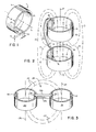
- Fig. 1 is a perspective view of a loop-gap resonator employed in the present invention;
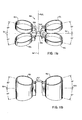
- Fig. is a perspective view of a pair of loop-gap resonators coupled to form an axial pair;
- Fig. 3 is a perspective view of a pair of loop-gap resonators coupled to form a planar pair;
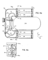
- Fig. 4a is an elevation view with parts cut away of a first preferred embodiment of the invention;
- Fig. 4b is a partial cross sectional view taken along the
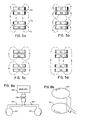
plane 4b―4b shown in Fig. 4; - Fig. 5a-5d are schematic representations of the four resonance modes of the embodiment of Fig. 4;
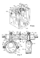
- Fig. 6 is a perspective view of a second preferred embodiment of the invention;
- Fig. 7 is an elevation view with parts cut away of the support arm and loop-gap resonators which form a part of the embodiment of Fig. 6;
- Figs. 8a and 8b are an electrical schematic diagrams of the coupling coils which form a part of the embodiment of Fig. 6;
- Fig. 9 is a schematic representation of an NMR scanner which employs the present invention;
- Fig. 10 is an electrical schematic diagram of the NMR scanner of Fig. 9; and
- Figs. 11 a and 11b are perspective views of a third preferred embodiment of the invention.
- Referring particularly to Fig. 1, the loop-gap resonator 1 which is employed in the present invention is a lumped circuit resonator which resonates at a radio frequency determined by its geometry. The lumped circuit resonator 1 has dimensions which are much less than the wavelength of the radio frequency signal at which it resonates. The capacitive and inductive elements are identifiable and the electromagnetic field oscillates between a magnetic field generated by the inductive element and an electric field generated by the capacitive element.
- The inductive element in the resonator 1 is the loop, or ring, formed by two
metallic pieces 2 and 3, and the capacitive element is thelongitudinal gaps pieces 2 and 3. The magnetic field produced by the resonator 1 is concentrated along a central axis 6, and the electric field is concentrated in thegaps gaps 


- e = the dielectric constant of the material in the gaps;
- p = the permeability of free space;
- n = the number of gaps, each having dimensions tm and Wm; and
- Z = the length of the resonator 1 in the direction of the central axis 6.
- There are a number of characteristics of the loop-gap resonator which are important when applying them to practical use. First, the length (Z) has virtually no effect on the resonant frequency. Second, one or more gaps may be employed and these need not be of equal dimensions or provide equal capacitance. The loop need not be circular, although there are often advantages to a circular construction as will be described in more detail below. And finally, energy may be applied or removed from the loop-gap resonator in either of two ways. Energy may be inductively coupled to or from the resonator by a conductive loop which encircles magnetic flux flowing through the loops and which connects to the end of a transmission line. Alternatively, energy can be capacitively coupled to or from the resonator by connecting the transmission line to the plates of one of the resonator's capacitive elements through an impedance matching network.
- Refering to Fig. 2, the present invention employs two loop-
gap resonators 10 and 11 which are spaced from one another to define a region 12 therebetween for receiving a material to be examined. When placed next to each other in this manner, the loop-gap resonators 10 and 11 will resonate in two modes. The first mode, referred to herein as the "unlinked" mode, is indicated by the dashedlines 13 and 14 which represent the paths of the magnetic flux flowing through each loop-gap resonator 10 and 11 in the opposite directions. The second resonant mode, referred to herein as the "linked" mode, is indicated by the dashed lines 17 which represent the paths of the magnetic flux flowing through eachresonator 10 and 11 in the same direction. When the loop-gap resonators 10 and 11 are closely spaced, the frequency of each of these resonant modes is substantially different due tothe mutual inductance. However, when the: loop-gap resonators 10 and 11 are spaced apart as shown in Fig. 2 to define the region 12, these resonant frequencies merge together. As a result the sensitivity in the region 12 to an FID signal at this merged frequency is not uniform. The solution is to suppress the undesired resonant mode. This is accomplished by providing electrical connections between the plates." of therespective gaps resonators 10 and 11. By forcing the electric potential between corresponding plates in therespective gaps lines 13 and 14 are not produced. As a result, the resonator pair operate in their linked resonant mode to produce a relatively uniform sensitivity in the region 12. While the electrical connection can be made in a number of ways, in the preferred embodiment a pair of flexible, insulated wires 18 are employed for this purpose. - In the embodiment of Fig. 2 the central axes of the respective loop-
gap resonators 10 and 11 are aligned along acommon axis 19. This arrangement is referred to hereinafter as an "axial pair". As will become apparent from the description below, this arrangement is particularly well suited for producing images of certain portions of the human anatomy, such as a patient's arms or legs. - Referring particularly to Fig. 3, the loop-
gap resonators 30 and 31 in a second embodiment of the invention are aligned side-by-side to provide a "planar pair" which produces a region of relatively uniform sensitivity at 32. A pair ofplates lines 37. In this planar pair orientation thecentral axes 38 and 39 of the respective loop-gap resonators 30 and 31 are not coaxial, but are substantially parallel to each other. - There are a number of other noteworthy variations in this second embodiment. First; the connecting
plates gap resonators 30 and 31, they will not couple with a uniform excitation field regardless of its orientation. Thus, the planar pair may be isolated from a circularly polarized excitation field. - In addition, each loop-
gap resonator 30 and 31 includes asecond gap 40 and 41 respectively, which also contributes to the resonant frequency of the linked pair. Perhaps more importantly, it has been discovered that by using loop-gap resonators with a plurality of gaps as shown in Fig. 3, the sensitivity of the local probe to changes in the dielectric properties of the subject being examined can be reduced. As a result, the necessity of retuning the local probe to the desired resonant frequency when the probe is moved to different regions of the anatomy or is applied to different patients is substantially reduced. - If there are n identical gaps in the loop-gap resonator, each of these gaps has a capacitance of n x C, where C is the total capacitance of the loop-gap resonator. The energy stored in each gap is(n x C)(V')2 and the total energy is n x
 (n x C)(V')2 lf a single gap were used, the total energy would beCV2, and since these energies must be equal, then:
- Referring particularly to Fig. 4a, a pair of loop-
gap resonators plastic supporting structure 52 and are oriented to form an axial pair. The supportingstructure 52 is formed as twoseparate sections 52a and 52b, with each section having a circularcylindrical tube arm arm 54a telescopes within thearm 54b and afastener 55 extends through thearms slots arm 54a, and by loosening thefastener 55, the length of thearms gap resonators - Referring particularly to Figs. 4a and 4b, the gaps -58 and. 59 on the respective loop-
gap resonators uniform sensitivity 60 therebetween. These connections are made by two pieces of 300ohm antenna wire 61 and 62 which are equal in length and are joined at a variable capacitor 63 that is mounted in the wall of thearm 54b. By adjusting the value of the capacitor 63, the resonant frequency of theaxial pair region 60. An electrical signal is produced across the plates of the capacitor 63 by the FID signal, and this electrical signal may be coupled to the inputs of a receiver. This construction is particularly well suited for examining the arms and legs of a patient, as well as portions of the torso. - As indicated above, when the local probe is used to receive the FID signals, a separate coil is employed to produce the excitation field B,. During the generation of each excitation pulse B1, it is highly desirable to minimize the magnitude of the signal which this field induces in the local probe. Referring again to Fig. 4a, the component of the excitation field Bi in the direction indicated by an x axis 65 will not induce a voltage in the loop-
gap resonators gap resonators - To substantially eliminate this problem, a second, substantially identical loop-
gap resonator gap resonators gap resonators gap resonators wires 61 and 62 to the loop-gap resonators electrical cross connections 71 which are made betweencorresponding gaps resonator pair electrical cross connections 72 which are made betweencorresponding gaps resonator pair - Referring again to Fig. 4a, an FID signal emanating from the
region 60 will induce a signal in theaxial pair gap resonators - The local probe of Fig. 4 may, of course, be constructed in a variety of sizes to operate at different frequencies. In the preferred embodiment each loop-
gap resonator layer 76 as shown in Fig. 4b. These inward extending tabs are trimmed in size to tune theaxial pair - A second preferred embodiment of the invention which is particularly suited for examining the head and neck regions of a human subject is shown in Figs. 6 and 7. A supporting structure includes a base 100 having a pair of attached
upright sidewalls contoured opening 103 is formed in the base 100 for receiving the back of the subject's head and neck, and the bottom of the base is contoured to rest securely in the bore of the NMR scanner's magnet. The base 100 and thesidewalls - Two pairs of
vertical slots 104 and 105 are formed in therespective sidewalls support arm 106. Threadedrods 107 extend from the ends of thesupport arm 106 and are received in one of the slot pairs 104 and 105. A knurled,brass nut 108 is received on eachrod 107 and may be tightened to fasten thesupport arm 106 at the desired height and angular orientation in theslots 104 and 105. - Supported from the
arm 106 is a pair ofyokes bottom 115 of thesupport arm 106 and which include threadedrods 112 that extend out throughopening 113 in itstop wall 114.Knurled brass nuts 116 are received on the threadedrods 112, and these may be tightened to securely fasten theyokes yokes openings 111 and 113, and theopenings 111 and 113 are elongated along the axis of thesupport arm 106 to enable the lateral spacing of theyokes - Each
yoke arms 120 which extend away from thesupport arm 106 and which rotatably support acylindrical probe assembly 121 therebetween. Theprobe assemblies 121 are identical, and each includes a circularcylindrical tube 122 made of polyvinyl chloride. A pair of threadedrods 123 extend radially outward from opposite sides of thetubes 122 and these are rotatably received in openings in the ends of theyoke arms 120.Knurled brass nuts 124 are received on the ends of the threadedrods 123, and these may be hand tightened to lock theprobe assemblies 121 to theyokes - Referring still to Figs. 6 and 7, each
probe assembly 121 includes a pair of loop-gap resonators 125 formed on the inside surface of thetube 122. The loop in eachresonator 125 is formed by three strips of copper foil which are bonded to thetube 122, and the ends of each strip are folded radially inward to form three gaps, orcapacitive elements 126. Each loop has a radius (r) of 3.8 cm (1.5 inches) and an axial length (Z) of 1.3 cm (.5 inches). The two loop-gap resonators 125 are spaced apart 0.64 cm (.25 inches) and thecapacitive elements 126 are trimmed to provide a resonant frequency of 63.89 MHz. - As explained above with respect to the structure of Fig. 4a, the two sets of loop-gap resonators have four resonant modes, and only one of these is desirable. One of the undesired modes is suppressed by
cross connections 127 at one of thegaps 126 in each of the loop-gap resonators 125 as described above. One of the loop-gap resonators 125 from eachprobe assembly 121 are connected together to suppress two of the other undesired resonant modes. As described-above, this is accomplished by electrically connecting the corresponding plates at one of theirrespective gaps 126 by flexible,insulated wires wires support arm 106 where they connect together across avariable capacitor 132. Thecapacitor 132 is mounted in thebottom wall 115 of thesupport arm 106 and its value can be manually adjusted to precisely tune the linked pair to the frequency of the FID signal. - The shape and size of the region of sensitivity thus produced will depend on the physical orientation of the probe assemblies 121: They can be positioned as a linked axial pair as in Fig. 2, or they can be positioned as a linked planar pair as in Figs. 3 and 6. They can also be locked into a variety of other positions ranging between the axial pair and planar pair orientàtions. When employed in the supporting structure 100―102, this embodiment of the invention is well suited for examining the head and neck regions of a patient. The
suport arm 106 can also be removed from this support structure and used separately to image other regions such as the spine. - Referring particularly to Figs. 7 and 8, the FID signals which are detected by the
probe assemblies 121 are magnetically coupled, to atransmission line 135 that connects to thereceiver 136 of the NMR scanner. This is accomplished by mounting acoupling coil 137 within eachprobe assembly 121. The coupling coils 137 are made of #12 copper wire and each is a single turn having a diameter of approximately 3.8 cm (1.5 inches). The ends of the coupling coils 137 are connected tocoaxial cables support arm 106. One lead of eachcable transmission line 135 through aconnector 140, and the other leads in eachcable probe assemblies 121 are oriented as a planar pair, any currents induced in the coupling coils 137 by a a uniform excitation field (B,) are equal and opposite. Similarly, as shown in Fig. 8b; when theprobe assemblies 121 are oriented as an axial pair any currents induced by a uniform excitation field (B1) are equal and opposite. This symmetry minimizes the electrical signal which will be applied to thereceiver 136 during the excitation period of each measurement cycle. - Other variations from the axial pair and planar pair constructions are possible withouf departing from the spirit of the present invention. In the embodiment shown in Fig. 11a, for example, loop-
gap resonators wires region 154 of relatively uniform sensitivity therebetween. This embodiment is specifically designed to image sections of the human spinal column, and: to more accurately focus, or shape, thesensitivity region 154 to this region of interest. To accomplish this, each loop-gap resonator - While this particular orientation improves the quality of spinal column images, the loop-
gap resonator pair 150―151 is no longer geometrically isolated from the excitation field B1. One solution to this problem is to add a pair of separate, axial loop-gap resonators as was done in the embodiments of Figs. 4a and 6. However, there is yet another solution when tilting a planar pair in this fashion. A second pair of tilted loop-gap resonators 155 and 156 may be connected to thefirst pair wires resonator 150 to resonate therewith in the linked mode. Similarly, the loop-gap resonator 156 is connected to the loop-gap resonator 151 bywires x axis 161 and abouta y axis 162. This symmetry isolates the probe from a uniform excitation field B1 of any orientation. - A substantially equivalent structure is shown in Fig. 11 b, where two loop-
gap resonators gap resonator axis 168 through their common plane to shape the region of uniform sensitivity while maintaining symmetry. - Referring particularly to Figs. 9 and 10, although the present invention may be easily implemented in a variety of NMR scanner or NMR spectrometer structures, the preferred embodiments of the invention have been employed to detect the FID signals produced in a large, whole- body NMRscanner. Referring particularly to Fig. 9, this scanner employs a
polarizing magnet 200 which is comprised of four circularcylindrical segments 201―204 of sufficient size to receive a table 205. A patient may be placed on the table 205 and any portion of his body may be scanned by suitably positioning him with respect to a set of excitation coils 206. Thepolarizing magnet 200 produces a strong magnetic field Bz which is constant and homogeneous within the space defined by the excitation coils 206. The excitation coils 206 produce an excitation field B1 which is in the transverse plane, perpendicular to the polarizing field B2. The excitation field B1 oscillates at a radio frequency 1/12/0 = 63.89 MHz and it is applied as one or more pulses during each measurement cycle. There are also three sets of gradient coifs 207-209 (not shown in Fig. 9) which produce magnetic field gradients in the region between the excitation coils 206. - - Referring particularly to Fig. 10, the control system for the NMR scanner includes a set of four static power converters 215-218 which connect to an a.c.
power source 219. The static converters 215-218 produce d.c. currents for therespective coils processor 220. Both the magnitude and the direction of the gradient fields in the x, y and z directions are controlled by theprocessor 220 to "scan" a region between the excitation coils 206 and reconstruct an image from the FID signals which are produced. - The
processor 220 also controls the operation of anexcitation field oscillator 221 which is connected to the excitation coils 206 and which is turned on and off during each measurement cycle of the scanning process. Theoscillator 221 also provides a reference signal to a receiver andphase detector circuit 222 which in turn is connected to receive the FID signal from a local probe 223. The FID signal is amplified and detected by thecircuit 222 and is then applied to the input of an analog-to-digital converter 224. The digitized FID signals are processed using well-known NMR imaging techniques, and image data is produced by theprocessor 220 for display on aCRT 225. - By using the local probes of the present inven- tion, images of improved quality are produced. This improvement results from a number of factors. The loop-gap resonators employed in the local probes have a higher quality factor than prior probes or receiver coils used for this purpose. This improves the signal-to-noise ratio of the FID signals applied to the
receiver 222, and hence, the signal quality. As described above, the present invention also enables local probes to be configured to image specific parts of the human anatomy. By properly orienting the loop-gap resonators, the region of sensitivity of the local probe may be "shaped" to encompass only the region of interest in the human subject. This improves FID signal quality and the quality of the resulting image. - And finally, the local probe of the present invention may be constructed to provide geometric isolation from the excitation field (BI). As a result, the
receiver 222 need not be turned off each time the excitation coils 206 are energized. This not only simplifies the control circuitry, but also, it enables the local probe 223 to be oriented in any direction within the excitation field (B1) without inducing excessive currents or voltages. This is particularly important where the excitation coils 206 are configured to produce a circularly polarized excitation field (B,), which has components in both the x and y directions. Prior local probes cannot be oriented to receive the FID signals and avoid coupling with both of these excitation field components. This same geometric isolation characteristic is also of benefit during the receive portion of each measurement cycle, since it provides some degree of immunity to extraneous noises produced by other coils or sources.
Claims (20)
Applications Claiming Priority (2)
| Application Number | Priority Date | Filing Date | Title |
|---|---|---|---|
| US06/731,923 US4724389A (en) | 1985-05-08 | 1985-05-08 | Loop-gap resonator for localized NMR imaging |
| US731923 | 1985-05-08 |
Publications (3)
| Publication Number | Publication Date |
|---|---|
| EP0201084A2 EP0201084A2 (en) | 1986-11-12 |
| EP0201084A3 EP0201084A3 (en) | 1987-09-30 |
| EP0201084B1 true EP0201084B1 (en) | 1990-09-05 |
Family
ID=24941467
Family Applications (1)
| Application Number | Title | Priority Date | Filing Date |
|---|---|---|---|
| EP86106199A Expired - Lifetime EP0201084B1 (en) | 1985-05-08 | 1986-05-06 | A local probe for use in nmr imaging |
Country Status (4)
| Country | Link |
|---|---|
| US (1) | US4724389A (en) |
| EP (1) | EP0201084B1 (en) |
| JP (1) | JPS6241651A (en) |
| DE (1) | DE3673860D1 (en) |
Cited By (1)
| Publication number | Priority date | Publication date | Assignee | Title |
|---|---|---|---|---|
| DE102005006725B4 (en) * | 2005-02-03 | 2010-06-02 | Bruker Biospin Gmbh | Apparatus and probe for determining a quantitative property of a sample substance by means of magnetic resonance |
Families Citing this family (44)
| Publication number | Priority date | Publication date | Assignee | Title |
|---|---|---|---|---|
| US4866387A (en) * | 1985-05-08 | 1989-09-12 | Mcw Research Foundation, Inc. | NMR detector network |
| US4721913A (en) * | 1985-05-08 | 1988-01-26 | Mcw Research Foundation, Inc. | NMR local coil network |
| NL8502612A (en) * | 1985-09-25 | 1987-04-16 | Philips Nv | MAGNETIC RESONANCE DEVICE WITH DETACHING SURFACE COIL DETECTION. |
| JPS6321049A (en) * | 1986-07-15 | 1988-01-28 | 工業技術院長 | Brain function measuring apparatus using neclear magnetic resonance phenomenon |
| EP0281787A1 (en) * | 1987-02-25 | 1988-09-14 | Siemens Aktiengesellschaft | Surface resonator for a nuclear spin resonance apparatus |
| FR2615040B1 (en) * | 1987-05-07 | 1990-02-16 | Thomson Cgr | PASSIVE DECOUPLING RECEIVING ANTENNA IN PARTICULAR FOR NUCLEAR MAGNETIC RESONANCE IMAGING APPARATUS |
| JPS645536A (en) * | 1987-06-29 | 1989-01-10 | Toshiba Corp | Magnetic resonance apparatus |
| US4799016A (en) * | 1987-07-31 | 1989-01-17 | General Electric Company | Dual frequency NMR surface coil |
| US4812761A (en) * | 1987-09-24 | 1989-03-14 | Board Of Regents, The University Of Texas System | Electrically parallel equal phase resonant loops for nuclear magnetic resonance surface coils |
| US5024229A (en) * | 1987-11-16 | 1991-06-18 | The University Of Rochester | Resonators for magnetic resonance imaging |
| US4812764A (en) * | 1988-03-31 | 1989-03-14 | Varian Associates, Inc. | Calibrated decoupling of tightly coupled concentric surface coils |
| US4878022A (en) * | 1988-10-14 | 1989-10-31 | The Regents Of The University Of California | Widened and shaped MRI surface coil having increased signal-to-noise ratio |
| US4926120A (en) * | 1988-12-27 | 1990-05-15 | United Technologies Corporation | In-line metallic debris particle detection system |
| US5041791A (en) * | 1989-08-07 | 1991-08-20 | Washington University | Magnetic resonance RF probe with electromagnetically isolated transmitter and receiver coils |
| US5142232A (en) * | 1989-10-09 | 1992-08-25 | Sumitomo Special Metal Co., Ltd. | Electron spin resonance system |
| US5204628A (en) * | 1989-10-09 | 1993-04-20 | Sumitomo Special Metal Co., Ltd. | Electron spin resonance system |
| DE4122797C2 (en) * | 1991-07-10 | 1994-12-15 | Bruker Medizintech | Coil arrangement for measurements using magnetic resonance |
| US5432450A (en) * | 1993-03-09 | 1995-07-11 | The Five Oaks Research Institute | Truncated nuclear magnetic imaging probe |
| US5433717A (en) * | 1993-03-23 | 1995-07-18 | The Regents Of The University Of California | Magnetic resonance imaging assisted cryosurgery |
| US5542424A (en) * | 1993-03-25 | 1996-08-06 | Rochester Institute Of Technology | Resonator for magnetic resonance imaging |
| US5361764A (en) * | 1993-07-09 | 1994-11-08 | Grumman Aerospace Corporation | Magnetic resonance imaging foot coil assembly |
| US5500596A (en) * | 1994-04-28 | 1996-03-19 | Wisconsin Alumni Research Foundation | Local coil array for magnetic resonance imaging of the lower extremities |
| US5751146A (en) * | 1994-12-01 | 1998-05-12 | Magnetic Vision Technologies, Inc. | Surface coil for high resolution imaging |
| US7598739B2 (en) * | 1999-05-21 | 2009-10-06 | Regents Of The University Of Minnesota | Radio frequency gradient, shim and parallel imaging coil |
| JP2003500133A (en) | 1999-05-21 | 2003-01-07 | ザ ゼネラル ホスピタル コーポレーション | RF coil for imaging system |
| US6493572B1 (en) | 1999-09-30 | 2002-12-10 | Toshiba America Mri, Inc. | Inherently de-coupled sandwiched solenoidal array coil |
| US6788056B2 (en) * | 2000-07-31 | 2004-09-07 | Regents Of The University Of Minnesota | Radio frequency magnetic field unit with aperature |
| JP4672119B2 (en) * | 2000-08-11 | 2011-04-20 | 株式会社東芝 | High frequency coil for nuclear magnetic resonance imaging apparatus and nuclear magnetic resonance imaging apparatus |
| US6984980B2 (en) | 2002-02-14 | 2006-01-10 | Baker Hughes Incorporated | Method and apparatus for NMR sensor with loop-gap resonator |
| AUPS224702A0 (en) * | 2002-05-10 | 2002-06-13 | Thorlock International Limited | Transmit - receive coil system for nuclear quadrupole resonance signal detection in substances |
| AUPS322802A0 (en) * | 2002-06-26 | 2002-07-18 | Thorlock International Limited | Large volume scanner for nuclear quadrupole resonance measurements (#14) |
| DE10334170B3 (en) * | 2003-07-26 | 2005-06-02 | Physikalisch-Technische Bundesanstalt Braunschweig Und Berlin | Arrangement for generating high-frequency B1 fields in NMR with surface current antennas |
| EP1751571B1 (en) * | 2004-05-07 | 2020-07-15 | Regents Of The University Of Minnesota | Multi-current elements for magnetic resonance radio frequency coils |
| US8030926B2 (en) * | 2006-03-15 | 2011-10-04 | Albert Einstein College Of Medicine Of Yeshiva University | Surface coil arrays for simultaneous reception and transmission with a volume coil and uses thereof |
| US8314740B2 (en) * | 2007-09-06 | 2012-11-20 | Deka Products Limited Partnership | RFID system |
| US8059014B2 (en) * | 2008-03-21 | 2011-11-15 | Eldec Corporation | Aircraft tire pressure loop link |
| US8519869B2 (en) * | 2008-03-21 | 2013-08-27 | Eldec Corporation | Aircraft tire pressure loop link |
| US9614377B2 (en) | 2008-03-21 | 2017-04-04 | Eldec Corporation | Aircraft tire pressure sensor resonant loop link |
| US8215162B2 (en) | 2009-07-27 | 2012-07-10 | Eldec Corporation | Focused field antenna for passive RFID tire pressure sensor transponder |
| US9431856B2 (en) * | 2012-01-09 | 2016-08-30 | Pabellon, Inc. | Power transmission |
| US8823391B2 (en) * | 2012-02-14 | 2014-09-02 | Battelle Memorial Institute | Regenerative feedback resonant circuit |
| JP6178403B2 (en) * | 2012-03-30 | 2017-08-09 | エルデック コーポレイション | Aircraft tire pressure loop link |
| CN108431622B (en) * | 2016-03-14 | 2021-01-15 | 日本电子株式会社 | Inductive coupling in multiple resonance circuits in a nuclear magnetic resonance probe and method of use |
| DE102020204067A1 (en) * | 2020-03-30 | 2021-09-30 | Siemens Healthcare Gmbh | Local coil with detuning function |
Family Cites Families (20)
| Publication number | Priority date | Publication date | Assignee | Title |
|---|---|---|---|---|
| US3949388A (en) * | 1972-11-13 | 1976-04-06 | Monitron Industries, Inc. | Physiological sensor and transmitter |
| JPS49103693A (en) * | 1973-02-02 | 1974-10-01 | ||
| NL7314269A (en) * | 1973-10-17 | 1975-04-21 | Philips Nv | MICROWAVE DEVICE EQUIPPED WITH A 1/2 LAMBDA RESONATOR. |
| JPS5945097B2 (en) * | 1977-02-08 | 1984-11-02 | 日本電子株式会社 | High frequency circuit of nuclear magnetic resonance apparatus |
| US4093911A (en) * | 1977-02-22 | 1978-06-06 | Varian Associates, Inc. | Nuclear magnetic resonance spectrometer employing an improved resonance signal gating circuit |
| GB2076542B (en) * | 1980-05-21 | 1984-02-15 | Emi Ltd | Nmr imaging apparatus |
| US4394645A (en) * | 1981-09-10 | 1983-07-19 | Sensormatic Electronics Corporation | Electrical surveillance apparatus with moveable antenna elements |
| US4446429A (en) * | 1981-10-09 | 1984-05-01 | Medical College Of Wisconsin | Microwave resonator |
| US4435680A (en) * | 1981-10-09 | 1984-03-06 | Medical College Of Wisconsin | Microwave resonator structure |
| US4504788A (en) * | 1982-09-03 | 1985-03-12 | The Medical College Of Wisconsin, Inc. | Enclosed loop-gap resonator |
| US4516075A (en) * | 1983-01-04 | 1985-05-07 | Wisconsin Alumni Research Foundation | NMR scanner with motion zeugmatography |
| US4480239A (en) * | 1983-02-07 | 1984-10-30 | The Medical College Of Wisconsin Inc. | Loop-gap resonator network |
| US4607225A (en) * | 1983-07-19 | 1986-08-19 | Regents Of The University Of California | Apparatus and method for reducing spurious currents in NMR imaging apparatus induced by pulsed gradient fields |
| DE3340384A1 (en) * | 1983-11-08 | 1985-05-15 | Siemens AG, 1000 Berlin und 8000 München | HIGH-FREQUENCY DEVICE OF A NUCLEAR RESONANCE APPARATUS WITH A SURFACE COIL |
| FI73320C (en) * | 1984-01-20 | 1987-09-10 | Instrumentarium Oy | NMR SPOLARRANGEMANG. |
| JPS60171439A (en) * | 1984-02-16 | 1985-09-04 | Yokogawa Hokushin Electric Corp | Coil for nmr image diagnosing apparatus |
| JPS60136108U (en) * | 1984-02-17 | 1985-09-10 | 三菱電機株式会社 | High frequency coil for nuclear magnetic resonance equipment |
| GB2159958B (en) * | 1984-05-25 | 1988-03-02 | Picker Int Ltd | Rf field generating and detecting arrangements |
| US4636730A (en) * | 1984-08-16 | 1987-01-13 | General Electric Company | NMR spectroscopy body probes with at least one surface coil |
| US4570137A (en) * | 1984-09-04 | 1986-02-11 | Motorola, Inc. | Lumped-mode resonator |
-
1985
- 1985-05-08 US US06/731,923 patent/US4724389A/en not_active Expired - Lifetime
-
1986
- 1986-05-06 EP EP86106199A patent/EP0201084B1/en not_active Expired - Lifetime
- 1986-05-06 DE DE8686106199T patent/DE3673860D1/en not_active Expired - Lifetime
- 1986-05-08 JP JP61105777A patent/JPS6241651A/en active Granted
Cited By (1)
| Publication number | Priority date | Publication date | Assignee | Title |
|---|---|---|---|---|
| DE102005006725B4 (en) * | 2005-02-03 | 2010-06-02 | Bruker Biospin Gmbh | Apparatus and probe for determining a quantitative property of a sample substance by means of magnetic resonance |
Also Published As
| Publication number | Publication date |
|---|---|
| US4724389A (en) | 1988-02-09 |
| EP0201084A3 (en) | 1987-09-30 |
| DE3673860D1 (en) | 1990-10-11 |
| JPS6241651A (en) | 1987-02-23 |
| JPH0352741B2 (en) | 1991-08-12 |
| EP0201084A2 (en) | 1986-11-12 |
Similar Documents
| Publication | Publication Date | Title |
|---|---|---|
| EP0201084B1 (en) | A local probe for use in nmr imaging | |
| EP0301232B1 (en) | Dual frequency NMR surface coil | |
| US4733190A (en) | NMR local coil with adjustable spacing | |
| US4721913A (en) | NMR local coil network | |
| US4634980A (en) | Nuclear magnetic resonance radio frequency antenna | |
| US4740751A (en) | Whole body MRI resonator | |
| US4594566A (en) | High frequency rf coil for NMR device | |
| US4783641A (en) | NMR radio frequecny field coil with distributed current | |
| JP4004964B2 (en) | Transmitter and receiver coils for MR devices | |
| EP0359374B1 (en) | Magnetic resonance apparatus | |
| US6396271B1 (en) | Tunable birdcage transmitter coil | |
| US4694255A (en) | Radio frequency field coil for NMR | |
| EP0322192B1 (en) | Apparatus for dynamically disabling an NMR field coil | |
| US5274332A (en) | Inductively coupled multi-section radio frequency field coil for NMR | |
| US5212450A (en) | Radio frequency volume resonator for nuclear magnetic resonance | |
| EP0412749B1 (en) | Magnetic resonance probes | |
| US6169401B1 (en) | Flexible open quadrature highpass ladder structure RF surface coil in magnetic resonance imaging | |
| EP0580327B1 (en) | Magnetic resonance apparatus | |
| US5689189A (en) | Technique for designing distributed radio frequency coils and distributed radio frequency coils designed thereby | |
| JPS58124936A (en) | Device for generating and detecting component of magnetic field in magnetic resonance system | |
| JPH0693010B2 (en) | NMR radio frequency coil with improved axial magnetic field homogeneity | |
| JPH09103423A (en) | Magnetic resonance image pickup method and magnetic resonance image pickup device | |
| EP0177855B1 (en) | Radio frequency field coil for nmr | |
| US4841249A (en) | Truncated cone shaped surface resonator for nuclear magnetic resonance tomography | |
| GB2151791A (en) | RF Field coils for NMR apparatus |
Legal Events
| Date | Code | Title | Description |
|---|---|---|---|
| PUAI | Public reference made under article 153(3) epc to a published international application that has entered the european phase |
Free format text: ORIGINAL CODE: 0009012 |
|
| AK | Designated contracting states |
Kind code of ref document: A2 Designated state(s): CH DE FR GB LI NL |
|
| PUAL | Search report despatched |
Free format text: ORIGINAL CODE: 0009013 |
|
| AK | Designated contracting states |
Kind code of ref document: A3 Designated state(s): CH DE FR GB LI NL |
|
| 17P | Request for examination filed |
Effective date: 19880125 |
|
| 17Q | First examination report despatched |
Effective date: 19890531 |
|
| GRAA | (expected) grant |
Free format text: ORIGINAL CODE: 0009210 |
|
| AK | Designated contracting states |
Kind code of ref document: B1 Designated state(s): CH DE FR GB LI NL |
|
| REF | Corresponds to: |
Ref document number: 3673860 Country of ref document: DE Date of ref document: 19901011 |
|
| ET | Fr: translation filed | ||
| PLBE | No opposition filed within time limit |
Free format text: ORIGINAL CODE: 0009261 |
|
| STAA | Information on the status of an ep patent application or granted ep patent |
Free format text: STATUS: NO OPPOSITION FILED WITHIN TIME LIMIT |
|
| 26N | No opposition filed | ||
| REG | Reference to a national code |
Ref country code: GB Ref legal event code: IF02 |
|
| PGFP | Annual fee paid to national office [announced via postgrant information from national office to epo] |
Ref country code: GB Payment date: 20040426 Year of fee payment: 19 |
|
| PGFP | Annual fee paid to national office [announced via postgrant information from national office to epo] |
Ref country code: FR Payment date: 20040519 Year of fee payment: 19 |
|
| PGFP | Annual fee paid to national office [announced via postgrant information from national office to epo] |
Ref country code: CH Payment date: 20040524 Year of fee payment: 19 |
|
| PGFP | Annual fee paid to national office [announced via postgrant information from national office to epo] |
Ref country code: DE Payment date: 20050411 Year of fee payment: 20 |
|
| PG25 | Lapsed in a contracting state [announced via postgrant information from national office to epo] |
Ref country code: GB Free format text: LAPSE BECAUSE OF NON-PAYMENT OF DUE FEES Effective date: 20050506 |
|
| PGFP | Annual fee paid to national office [announced via postgrant information from national office to epo] |
Ref country code: NL Payment date: 20050518 Year of fee payment: 20 |
|
| PG25 | Lapsed in a contracting state [announced via postgrant information from national office to epo] |
Ref country code: LI Free format text: LAPSE BECAUSE OF NON-PAYMENT OF DUE FEES Effective date: 20050531 Ref country code: CH Free format text: LAPSE BECAUSE OF NON-PAYMENT OF DUE FEES Effective date: 20050531 |
|
| REG | Reference to a national code |
Ref country code: CH Ref legal event code: PL |
|
| GBPC | Gb: european patent ceased through non-payment of renewal fee |
Effective date: 20050506 |
|
| PG25 | Lapsed in a contracting state [announced via postgrant information from national office to epo] |
Ref country code: FR Free format text: LAPSE BECAUSE OF NON-PAYMENT OF DUE FEES Effective date: 20060131 |
|
| REG | Reference to a national code |
Ref country code: FR Ref legal event code: ST Effective date: 20060131 |
|
| PG25 | Lapsed in a contracting state [announced via postgrant information from national office to epo] |
Ref country code: NL Free format text: LAPSE BECAUSE OF EXPIRATION OF PROTECTION Effective date: 20060506 |
|
| NLV7 | Nl: ceased due to reaching the maximum lifetime of a patent |
Effective date: 20060506 |