EP0201894A2 - A control apparatus for a rotor supported by an electromagnetic bearing - Google Patents
A control apparatus for a rotor supported by an electromagnetic bearing Download PDFInfo
- Publication number
- EP0201894A2 EP0201894A2 EP86106410A EP86106410A EP0201894A2 EP 0201894 A2 EP0201894 A2 EP 0201894A2 EP 86106410 A EP86106410 A EP 86106410A EP 86106410 A EP86106410 A EP 86106410A EP 0201894 A2 EP0201894 A2 EP 0201894A2
- Authority
- EP
- European Patent Office
- Prior art keywords
- rotor
- signal
- filter
- directional
- servo circuit
- Prior art date
- Legal status (The legal status is an assumption and is not a legal conclusion. Google has not performed a legal analysis and makes no representation as to the accuracy of the status listed.)
- Granted
Links
Images


Classifications
-
- F—MECHANICAL ENGINEERING; LIGHTING; HEATING; WEAPONS; BLASTING
- F16—ENGINEERING ELEMENTS AND UNITS; GENERAL MEASURES FOR PRODUCING AND MAINTAINING EFFECTIVE FUNCTIONING OF MACHINES OR INSTALLATIONS; THERMAL INSULATION IN GENERAL
- F16C—SHAFTS; FLEXIBLE SHAFTS; ELEMENTS OR CRANKSHAFT MECHANISMS; ROTARY BODIES OTHER THAN GEARING ELEMENTS; BEARINGS
- F16C32/00—Bearings not otherwise provided for
- F16C32/04—Bearings not otherwise provided for using magnetic or electric supporting means
- F16C32/0406—Magnetic bearings
- F16C32/044—Active magnetic bearings
- F16C32/0444—Details of devices to control the actuation of the electromagnets
- F16C32/0451—Details of controllers, i.e. the units determining the power to be supplied, e.g. comparing elements, feedback arrangements with P.I.D. control
- F16C32/0453—Details of controllers, i.e. the units determining the power to be supplied, e.g. comparing elements, feedback arrangements with P.I.D. control for controlling two axes, i.e. combined control of x-axis and y-axis
-
- F—MECHANICAL ENGINEERING; LIGHTING; HEATING; WEAPONS; BLASTING
- F16—ENGINEERING ELEMENTS AND UNITS; GENERAL MEASURES FOR PRODUCING AND MAINTAINING EFFECTIVE FUNCTIONING OF MACHINES OR INSTALLATIONS; THERMAL INSULATION IN GENERAL
- F16C—SHAFTS; FLEXIBLE SHAFTS; ELEMENTS OR CRANKSHAFT MECHANISMS; ROTARY BODIES OTHER THAN GEARING ELEMENTS; BEARINGS
- F16C32/00—Bearings not otherwise provided for
- F16C32/04—Bearings not otherwise provided for using magnetic or electric supporting means
- F16C32/0406—Magnetic bearings
- F16C32/044—Active magnetic bearings
- F16C32/0474—Active magnetic bearings for rotary movement
- F16C32/048—Active magnetic bearings for rotary movement with active support of two degrees of freedom, e.g. radial magnetic bearings
Definitions
- the present invention relates to a control apparatus for a magnetic floating type rotor supported by an electromagnetic bearing. More particularly, it relates to an electromagnetic bearing control apparatus which is well suited to suppress a resonance amplitude of the unbalance vibration of a rotor.
- FIG. 1 The schematic setup of a rotary machine supported by an electromagnetic bearing, in which attractive electromagnets are used for bearing, is as shown in Fig. 1. First, an apparatus which performs a unidimensional position control in only an X-axial direction will be described.
- Coils 2 of electromagnets are arranged on the right and left of a rotor 1.
- a control current I flows through the left electromagnet coil 2, and the rotor 1 undergoes an attractive force so as to be displaced leftwards.
- a control current I flows through the right electromagnet coil 2 so as to establish an attractive force.
- the control current I is caused to flow through the electromagnet coil 2 on the opposite side in accordance with the rightward or leftward displacement of the rotor 1, to perform a servo control so that the rotor 1 may come to its central position owing to the resulting attractive force.
- At least one displacement sensor 3 is necessary for detecting the rightward and leftward displacements of the rotor 1.
- the displacement sensor 3 are e.g.; noncontacting sensors of the induction coil type, capacitance type, optical type, etc.
- a displacement signal x detected by the displacement sensor 3 is applied to a control circuit 4, which determines a control voltage v in accordance with the rightward or leftward deviation of the rotor 1 from the central position.
- the control voltage v is applied to either of power amplifiers 5 for the right and left electromagnet coils, and the control current I proportional thereto flows through the coil 2.
- the way of applying the control voltage v to the power amplifier 5 of the right or left coil is such that the self-centering effect of the rotor 1 is produced by the attractive force of the electromagnet coil 2.
- the servo circuit for the position control of the rotor 1 in the X direction is constructed of the single displacement sensor 1, the two right and left electromagnet coils 2 as well as the corresponding power amplifiers 5, and the single control circuit 4.
- the position control of the rotor 1 by the magnetic bearing requires two-dimensional position controls in X-and Y-directions as shown in Fig. 2. Therefore, the servo circuits of the same specifications are juxtaposed as two sets for the X direction and for the Y direction.
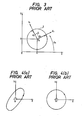
- Fig. 3 For elucidating the unbalance vibration, Fig. 3 is often used. It is assumed that the axis 0 of the rotor 1 lie at a displacement (x, y) as viewed from a space fixed axis O - XY system. The position of the center of gravity G of the rotor 1 as viewed from a rotating axis O r - X r Y r system fixed to the rotor 1 is assumed ( ⁇ x , ⁇ y ). Letting Q denote the rotating speed of the rotor 1, an angle defined between the OX-axis is a rotational angle which is expressed by ⁇ t (t; time).
- the vibration of the rotor 1 is detected in the X and Y directions, and the vibration frequency agrees with the rotating speed ⁇ , so that the vibration is expressed by the following forms:
- amplitudes in the X and Y directions are respectively denoted by a and a
- phase delays viewed y from the rotational angle ⁇ t are respectively denoted by ⁇ x and ⁇ y .
- the rotor vibration becomes the circular motion for the equal supporting rigidities of the bearing and becomes the elliptic orbit in the presence of anisotropy.
- the senses of the orbits are the same as the sense of the rotor rotation and are forward. Therefore, when a complex displacement Z indicated by the following equation is introduced: the rotor vibration is expressed in the following complex forms: where a, a f and a b are complex numbers expressing complex amplitudes respectively, and the following holds:
- the characteristics are sometimes anisotropic at low-speed rotations, but that they are more isotropic at higher-speed rotations owing to inertia.
- FIG. 5 An example of an unbalance vibration response curve is shown in Fig. 5.
- the two peaks M 1 and M 2 of the vibration amplitude on the lower side of the rotational speed are resonance points in the rigid body mode of the rotor.
- the third peak M 3 of the vibration amplitude is a resonance point in the bending mode of the rotor.
- the resonance points of the rigid body mode at low speed can be passed with their amplitudes suppressed by the adjustments of the proportional action, differential action and integral action of the servo control circuit.
- the resonance point of the bending mode of a high-speed rotation is inevitably passed with a sharp and large amplitude on account of an insufficient damping force.
- a servo control circuit for passing such a resonance point of the electromagnetic type rotor with the resonance amplitude suppressed is described in detail in Japanese Patent Provisional Publication No. 93853/'77.
- the principle of a tracking filter synchronous with a rotational speed, which has been known, and a method of controlling high damping impartation with the tracking filter will be described in divided stages.
- Fig. 6 is a schematic arrangement diagram of a tracking filter for elucidating the operating principle thereof.
- the output Z out of the tracking filter becomes a signal of only the component synchronous with the rotational speed:
- the input signal Z in is transformed into a rotating coordinate system when multiplied by e -i ⁇ t by means of a multiplier unit 10. That is: and the component a synchronous with the rotational speed becomes a D.C. component in the signal Z 1 of the rotating coordinate system. Besides, as seen from the first term of the above equation, the component having seemed a low frequency in the fixed coordinate system Z in turns into a high frequency component in the rotating coordinate system Z l .
- the signal Z 1 is passed through a low-pass filter 11 in order to extract the D.C. component a synchronous with the rotational speed.
- the output Z 2 of the filter is:
- the cutoff frequency of the low-pass filter is much lower than the rotational frequency. It is usually set at several Hz or a still lower value of approximately 0.1 Hz.
- the gain of this low-pass filter is 1 (one).
- the signal Z 2 of the rotating coordinate system is multiplied by e i ⁇ t by means of a multiplier unit 20 in order to inversely transform it into the fixed coordinate system.
- the output signal Z out is obtained which is such that only the component synchronous with the rotational frequency is extracted from within the input signal Z in as indicated by Eq. (10).
- e H2t is achieved by a process in which a cos or sin function synchronous with the rotational speed is operated with a matrix.
- This mathematical principle is changed into a circuit expression in Fig. 7.
- the circuit is of a feed system wherein, when the displacement signals x and y are input to proportion-plus-differential circuits 6 and 16, outputs ax + b* and ay + by are provided, respectively.
- the X-directional output signal ax + bx and Y-directional output signal ay + by thus derived are input to the tracking filter 7 synchronous with the rotational speed as described above.
- the first process in the tracking filter is a transformation into the rotating coordinate system based on the following equation:
- the second process signals are passed through low-pass filters of gains K (corresponding to the operation of integrating narrow bands) to obtain the signals x 2 and y 2 .
- the second process performs filtering operations for the X and Y directions separately from each other.
- the output signals x 0 and y 0 are obtained through the inverse transform into the fixed coordinate system:
- the output signals x 0 and y 0 are such that, in the vibration waveforms of the input signals x and y, only the components synchronous with the rotational speed have been extracted.
- the magnitudes of the coefficients a and b of the proportional-plus-differential circuits 6 and 16 or the value of the gain K of the low-pass filter By adjusting the magnitudes of the coefficients a and b of the proportional-plus-differential circuits 6 and 16 or the value of the gain K of the low-pass filter, the operations of advancing the phases of the rotational speed-synchronous components of the signals x and y can be afforded. That is, the actions of damping the resonance amplitudes can be achieved.
- the x displacement signal is input to the control circuit 4, while at the same time the x 0 signal with only the rotation-synchronous component extracted from within the above x displacement signal through the tracking filter 7 is used for the servo control.
- the Y direction By utilizing the x 0 and y 0 signals for the servo control, the components synchronous with the rotational speed can be endowed with the phase advance characteristics through the adjustments of the coefficients a and b or the gain K.
- the rotor is given the damping action, and the resonance points as shown in Fig. 5 can be passed with smaller amplitudes as indicated by a broken line.
- the velocity signals x and y are created from the detected displacement signals x and y through the differential circuits, and the displacement signals and the velocity signals are passed through the tracking filter 7 synchronized with the rotational speed.
- the bearing rigidity can be adjusted in accordance with the magnitudes of the displacement components, while the bearing damping can be adjusted in accordance with the magnitudes of the velocity components.
- An object of the present invention is to provide a control apparatus for an electromagnetic bearing in which the resonance amplitude of the rotational speed-synchronous unbalance vibration of a rotor supported by the electromagnetic bearing is lowered.
- the channels of an X-direction control circuit and a Y-direction control circuit are crossed to enhance a stability against a forward characteristic frequency.
- a tracking filter synchronized with a rotational frequency is jointly used.
- the enhancement of the stability is permitted against only the forward characteristic frequency near a resonance point, whereby the resonance amplitude of the unbalance vibration can be lowered.
- the constants k and k yy or those c xy and c yx act as bearing rigidities.
- the constants c xx and c yy act to damp the bearing, they exert the action of stabilizing the rotor.
- the constants k xy and k y x indicate the crossing terms of the X and Y directions and form causes for rendering the rotor vibration unstable.
- the forward unstable vibration called the oil whip arises in the rotor. That is, a stability against a forward characteristic frequency lowers, and a damping action weakens. Since the plain bearing is a passive element, the sign of the constant cannot be changed, and an action in the reverse direction cannot be produced.
- the rotation-synchronized tracking filter described before is jointly used, whereby the enhancement of the stability becomes possible as to only the forward characteristic frequency near a resonance point. On this occasion, the stability against the rearward characteristic frequency remains unchanged and does not lower.
- the enhancement of the characteristic frequency stability or damping capability is achieved as regards only the forward component.
- An unbalance vibration is a forward force, and the resonance peak thereof to be induced can be suppressed to a smaller resonance amplitude as the damping of the forward characteristic frequency is greater.
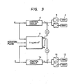
- a displacement signal x detecting the displacement of a rotor in an X direction is input to a control circuit 4, the calculated result of which is applied to a power amplifier 5 so as to cause a control current i n to flow through an electromagnet 2.
- Such a setup is the basic setup of a servo control system based on an electromagnetic bearing as illustrated in Fig. 2.
- the detected displacement signals x and y are input to a tracking filter 7 for components synchronous with a rotation speed, to extract only the rotation-synchronous components x n and y in the displacement vibration components of the rotor.
- the output signals x N and y N of the tracking filter 7. may be respectively regarded as differential signals y and -x N . Therefore, in order to afford a damping action in the Y direction, the x N signal is multiplied by a, and the product is additively input to the Y-direction channel. On the other hand, in order to afford a damping action in the X direction, the y N signal is multiplied by -a, and the product is subtractively input to the X-direction channel. In Fig. 9, the multiplication by -a is indicated as a subtractive input in the X direction..
- Fig. 10 shows a circuit arrangement well suited to the general case where the characteristics of the bearing are anisotropic to give rise to the unbalance vibration as illustrated by the elliptic orbit in Fig. 4 (a) or by Eq. (8).
- the method of suppressing the forward vibration a f e i ⁇ t of Eq. (8) is the same as in the preceding case of Fig. 9.
- the method of suppressing the rearward vibration component a be may be the reverse to the processing in the case of the forward component.
- a tracking filter to be used has the arrangement of a filter 8 for synchronization with a reverse-rotational speed.
- the coefficients of additive and subtractive inputs in the channel crossing of the outputs of the tracking filter 8 may be ⁇ 's whose signs are opposite to those of the coefficients a's.
- Fig. 11 shows experimental data obtained when the rotation-synchronous tracking filter and the channel crossing in the present invention were employed.
- the rotational speed is taken on the axis of abscissas, while the vibration amplitude is taken on the axis of ordinates.
- “ON” signifies that the operation of the present invention in Fig. 9 was performed.
Abstract
Description
- The present invention relates to a control apparatus for a magnetic floating type rotor supported by an electromagnetic bearing. More particularly, it relates to an electromagnetic bearing control apparatus which is well suited to suppress a resonance amplitude of the unbalance vibration of a rotor.
- The schematic setup of a rotary machine supported by an electromagnetic bearing, in which attractive electromagnets are used for bearing, is as shown in Fig. 1. First, an apparatus which performs a unidimensional position control in only an X-axial direction will be described.
-
Coils 2 of electromagnets are arranged on the right and left of arotor 1. When therotor 1 shifts rightwards under this state, a control current I flows through theleft electromagnet coil 2, and therotor 1 undergoes an attractive force so as to be displaced leftwards. To the contrary, when therotor 1 shifts leftwards, a control current I flows through theright electromagnet coil 2 so as to establish an attractive force. In this manner, the control current I is caused to flow through theelectromagnet coil 2 on the opposite side in accordance with the rightward or leftward displacement of therotor 1, to perform a servo control so that therotor 1 may come to its central position owing to the resulting attractive force. - In this case, at least one
displacement sensor 3 is necessary for detecting the rightward and leftward displacements of therotor 1. Often employed as thedisplacement sensor 3 are e.g.; noncontacting sensors of the induction coil type, capacitance type, optical type, etc. - A displacement signal x detected by the
displacement sensor 3 is applied to acontrol circuit 4, which determines a control voltage v in accordance with the rightward or leftward deviation of therotor 1 from the central position. The control voltage v is applied to either ofpower amplifiers 5 for the right and left electromagnet coils, and the control current I proportional thereto flows through thecoil 2. The way of applying the control voltage v to thepower amplifier 5 of the right or left coil is such that the self-centering effect of therotor 1 is produced by the attractive force of theelectromagnet coil 2. - As thus far described, the servo circuit for the position control of the
rotor 1 in the X direction is constructed of thesingle displacement sensor 1, the two right andleft electromagnet coils 2 as well as thecorresponding power amplifiers 5, and thesingle control circuit 4. In general, the position control of therotor 1 by the magnetic bearing requires two-dimensional position controls in X-and Y-directions as shown in Fig. 2. Therefore, the servo circuits of the same specifications are juxtaposed as two sets for the X direction and for the Y direction. - In Fig. 2, portions having the same functions as in Fig. 1 are indicated by the same symbols.
- Next, the features of the vibrations of a rotation axis will be explained. For elucidating the unbalance vibration, Fig. 3 is often used. It is assumed that the
axis 0 of therotor 1 lie at a displacement (x, y) as viewed from a space fixed axis O - XY system. The position of the center of gravity G of therotor 1 as viewed from a rotating axis Or - XrYr system fixed to therotor 1 is assumed (εx, εy). Letting Q denote the rotating speed of therotor 1, an angle defined between the OX-axis is a rotational angle which is expressed by Ωt (t; time). - When such symbols are assigned, forces acting on the
rotor 1 due to unbalance are as follows:

- On the other hand, the vibration of the
rotor 1 is detected in the X and Y directions, and the vibration frequency agrees with the rotating speed Ω, so that the vibration is expressed by the following forms:
- When a supporting rigidity based on the electromagnets through the servo control circuit in the X direction is equal to the same in the Y direction, namely, when the supporting rigidities of the bearing in the X direction and the Y direction are set to be isotropic, the vibration amplitudes in the X direction and the Y direction are equal to each other. Moreover, the phase difference between both the vibration components is 90°, and the X-directional vibration leads over the Y-directional vibration by 90°. These are expressed by the following equations:

- These are a natural result for the reason that the unbalance force F acting on the rotor is isotropic in the X and Y directions as indicated by Eq. (2) and that the characteristics of the bearing to receive the unbalance force are also isotropic. The rotor vibration at this time is expressed as follows:

- As stated above, the rotor vibration becomes the circular motion for the equal supporting rigidities of the bearing and becomes the elliptic orbit in the presence of anisotropy. The senses of the orbits are the same as the sense of the rotor rotation and are forward. Therefore, when a complex displacement Z indicated by the following equation is introduced:


- In the case of the electromagnetic bearing support, it is generally true that the characteristics are sometimes anisotropic at low-speed rotations, but that they are more isotropic at higher-speed rotations owing to inertia.
- An example of an unbalance vibration response curve is shown in Fig. 5. The two peaks M1 and M2 of the vibration amplitude on the lower side of the rotational speed are resonance points in the rigid body mode of the rotor. The third peak M3 of the vibration amplitude is a resonance point in the bending mode of the rotor. Regarding the conventional rotor supported by the magnetic bearing, the resonance points of the rigid body mode at low speed can be passed with their amplitudes suppressed by the adjustments of the proportional action, differential action and integral action of the servo control circuit. The resonance point of the bending mode of a high-speed rotation, however, is inevitably passed with a sharp and large amplitude on account of an insufficient damping force. It is, rather, common that the rotor cannot be operated in excess of a rotational speed corresponding to the bending mode resonance point because the resonance amplitude of the bending mode cannot be suppressed even when those of the rigid body mode can be suppressed by skillfully adjusting the servo control circuit.
- A servo control circuit for passing such a resonance point of the electromagnetic type rotor with the resonance amplitude suppressed is described in detail in Japanese Patent Provisional Publication No. 93853/'77. In order to grasp the published invention, the principle of a tracking filter synchronous with a rotational speed, which has been known, and a method of controlling high damping impartation with the tracking filter will be described in divided stages.
- The general features of the rotor vibration in the case where the rotor is rotating in a high-speed rotation region will be explained in conjunction with Fig. 2. It is assumed that the rotor be rotating near the bending mode resonance point M3 shown in Fig. 5. As the rotor vibration on this occasion, the forward vibration synchronous with the rotational frequency attributed to the unbalance is the principal component, and besides, the fluctuating vibration of the rotor attributed to external forces such as the shaking of a casing develops. The vibration frequency of the fluctuating vibration is close to the natural frequency of the rigid body mode and is lower than the rotational frequency. Therefore, the amplitude Z of the rotor vibration is written in the following complex from by applying the aforementioned equation (7):
-

- Fig. 6 is a schematic arrangement diagram of a tracking filter for elucidating the operating principle thereof. When the amplitude Zin is input, the output Zout of the tracking filter becomes a signal of only the component synchronous with the rotational speed:

- In addition, the input signal Zin is transformed into a rotating coordinate system when multiplied by e-iΩt by means of a
multiplier unit 10. That is:
- Here, the signal Z1 is passed through a low-
pass filter 11 in order to extract the D.C. component a synchronous with the rotational speed. The output Z2 of the filter is:
- Subsequently, the signal Z2 of the rotating coordinate system is multiplied by eiΩt by means of a
multiplier unit 20 in order to inversely transform it into the fixed coordinate system. As a result, the output signal Zout is obtained which is such that only the component synchronous with the rotational frequency is extracted from within the input signal Zin as indicated by Eq. (10). - The above is the principle of the filter for the component synchronous with the rotational speed. The filter is called the tracking filter when it follows up the
rotational speed 0. eH2t is achieved by a process in which a cos or sin function synchronous with the rotational speed is operated with a matrix. This mathematical principle is changed into a circuit expression in Fig. 7. In this figure, numeral 9 designates a generator which receives rotation pulses and generates sin and cos waves synchronous with them. Inputs xin and yin (Zin = xin + iyin) are subjected to a matrix operation T by anoperation unit 15, to obtain x1 and y1 (Z1= x1 + iy1):
- Thereafter, x1 and y1 are passed through low-
pass filters matrix operation unit 19, to find xout and y out (zout = xout + iyout):
- In this way, only the rotation-synchronous components can be extracted from within the x displacement signal and y displacement signal by the actual electronic circuit.
- Next, the resonant amplitude reduction method employing this tracking filter synchronous with the rotational speed as described in Japanese Patent Provisional Publication No. 93853/177 will be described with reference to Fig. 8.
- It is assumed that the displacements of the rotor in the X direction and the Y direction have been detected as x and y. The circuit is of a feed system wherein, when the displacement signals x and y are input to proportion-plus-
differential circuits tracking filter 7 synchronous with the rotational speed as described above. - The first process in the tracking filter is a transformation into the rotating coordinate system based on the following equation:

- By the second process, signals are passed through low-pass filters of gains K (corresponding to the operation of integrating narrow bands) to obtain the signals x2 and y2. The second process performs filtering operations for the X and Y directions separately from each other. By the third process, the output signals x0 and y0 are obtained through the inverse transform into the fixed coordinate system:

- The output signals x0 and y0 are such that, in the vibration waveforms of the input signals x and y, only the components synchronous with the rotational speed have been extracted. By adjusting the magnitudes of the coefficients a and b of the proportional-plus-
differential circuits - In the critical frequency damping equipment shown in Fig. 8, for the purpose of reducing the resonance amplitude in the X direction by way of example, the x displacement signal is input to the
control circuit 4, while at the same time the x0 signal with only the rotation-synchronous component extracted from within the above x displacement signal through the trackingfilter 7 is used for the servo control. The same applies to the Y direction. By utilizing the x0 and y0 signals for the servo control, the components synchronous with the rotational speed can be endowed with the phase advance characteristics through the adjustments of the coefficients a and b or the gain K. Thus, the rotor is given the damping action, and the resonance points as shown in Fig. 5 can be passed with smaller amplitudes as indicated by a broken line. - Such a control system, however, has the disadvantage that the velocity signals (x, y) need to be created from the displacement signals (x, y) by the proportional-plus-
differential circuits - The essence of this system is as stated below. The velocity signals x and y are created from the detected displacement signals x and y through the differential circuits, and the displacement signals and the velocity signals are passed through the tracking
filter 7 synchronized with the rotational speed. Thus, only the rotation-synchronous components of the displacements and velocities are extracted so as to be supplied for the control of only the unbalance vibration components thereof. The bearing rigidity can be adjusted in accordance with the magnitudes of the displacement components, while the bearing damping can be adjusted in accordance with the magnitudes of the velocity components. - An object of the present invention is to provide a control apparatus for an electromagnetic bearing in which the resonance amplitude of the rotational speed-synchronous unbalance vibration of a rotor supported by the electromagnetic bearing is lowered.
- In the control apparatus for an electromagnetic bearing according to the present invention, the channels of an X-direction control circuit and a Y-direction control circuit are crossed to enhance a stability against a forward characteristic frequency. Besides, in order to solve the problem that a stability against a coexisting rearward characteristic frequency lowers without any measure, a tracking filter synchronized with a rotational frequency is jointly used. Thus, the enhancement of the stability is permitted against only the forward characteristic frequency near a resonance point, whereby the resonance amplitude of the unbalance vibration can be lowered.
- Fig. 1 is a diagram for explaining the servo control operation of an electromagnetic bearing in a prior art;
- Fig. 2 is a diagram of the servo circuit arrangement of a rotor supported by an electromagnetic bearing in a prior art;
- Fig. 3 is a dynamic model diagram showing the displacement and unbalance of a rotor in a.prior art;
- Figs. 4(a) and 4(b) are diagrams each showing the shaking locus of the axis of a rotor under an unbalance vibration in a prior art;
- Fig. 5 is a diagram showing unbalance vibration responce curves in a prior art and in the present invention;
- Fig. 6 is a diagram for explaining the principle of a known filter synchronized with a rotational speed;
- Fig. 7 is a circuit arrangement diagram of a prior-art tracking filter synchronized with a rotational speed;
- Fig. 8 is a block diagram of a prior-art equipment for damping a critical frequency;
- Fig. 9 is a block diagram showing an embodiment of a servo control system according to the present invention;
- Fig. 10 is a block diagram of a servo control system based on an embodiment of the present invention in the case of anisotropic supporting characteristics; and
- Fig. 11 is a graph of test data in the present invention.
- In a rotor supported by plain bearings, it is known that a self-excited vibration called 'oil whip' develops. The causes will be considered. The reaction of an oil film in the plain bearing is expressed with respect to the displacement and velocity of the rotor, as follows:

- where Fx, Fy: reaction forces of the bearing in X and Y directions,
- kij (i, j = x, y): elastic constant of the oil film of the plain bearing,
- cij (i, j = x, y): damping constant of the oil film of the plain bearing.
- Conceptually speaking, the constants k and kyy or those cxy and cyx act as bearing rigidities. In addition, since the constants cxx and cyy act to damp the bearing, they exert the action of stabilizing the rotor. Meanwhile, the constants kxy and k yx indicate the crossing terms of the X and Y directions and form causes for rendering the rotor vibration unstable. Particularly at a rotational frequency for which kxy > 0 and kyx < 0 holds, the forward unstable vibration called the oil whip arises in the rotor. That is, a stability against a forward characteristic frequency lowers, and a damping action weakens. Since the plain bearing is a passive element, the sign of the constant cannot be changed, and an action in the reverse direction cannot be produced.
- With an electromagnetic bearing, however, the sign can be reversed by the arrangement of an electronic circuit so as to produce the action in the reverse direction, namely, the damping action. That is, when the channels of an X-direction control circuit and a Y-direction control circuit are crossed so as to establish k xy < 0 and kyx > 0, the stability against the forward characteristic frequency can be enhanced. Besides, it is undeniable that, according to such crossing of the channels, a stability against a coexisting rearward characteristic frequency lowers.
- Therefore, the rotation-synchronized tracking filter described before is jointly used, whereby the enhancement of the stability becomes possible as to only the forward characteristic frequency near a resonance point. On this occasion, the stability against the rearward characteristic frequency remains unchanged and does not lower.
- In this manner, using both the channel crossing and the rotation-synchronized tracking filter, the enhancement of the characteristic frequency stability or damping capability is achieved as regards only the forward component. An unbalance vibration is a forward force, and the resonance peak thereof to be induced can be suppressed to a smaller resonance amplitude as the damping of the forward characteristic frequency is greater.
- Now, an embodiment of the present invention will be described with reference to Fig. 9. A displacement signal x detecting the displacement of a rotor in an X direction is input to a
control circuit 4, the calculated result of which is applied to apower amplifier 5 so as to cause a control current in to flow through anelectromagnet 2. The same applied to a Y direction. Such a setup is the basic setup of a servo control system based on an electromagnetic bearing as illustrated in Fig. 2. - The detected displacement signals x and y are input to a
tracking filter 7 for components synchronous with a rotation speed, to extract only the rotation-synchronous components xn and y in the displacement vibration components of the rotor. When the bearing is isotropic, the unbalance vibration thereof ZN = xN + iyN becomes:

- To be noteworthy here is that the following relations hold:

- When note is taken of only the unbalance vibration components, Eqs. (20) hold, and hence, the output signals xN and yN of the tracking filter 7.may be respectively regarded as differential signals y and -xN. Therefore, in order to afford a damping action in the Y direction, the xN signal is multiplied by a, and the product is additively input to the Y-direction channel. On the other hand, in order to afford a damping action in the X direction, the yN signal is multiplied by -a, and the product is subtractively input to the X-direction channel. In Fig. 9, the multiplication by -a is indicated as a subtractive input in the X direction..
- In this manner, the additive and subtractive inputs are applied crossing the channels, whereby reaction forces for the components synchronous with the rotational speed are expressed as:


- This corresponds to the fact that
k xy < 0 andk yx > 0 are set. Therefore, the goal of enchaning the damping capability for the forward vibration of the rotor is accomplished. - The greater coefficient α which is used for the additive and subtractive inputs in the channel crossing becomes the better is the damping effect. Since, however, there is the restriction of preventing the saturation of the electronic circuit, the gain may be adjusted so as to establish an appropriate value of the resonance amplitude.
- Fig. 10 shows a circuit arrangement well suited to the general case where the characteristics of the bearing are anisotropic to give rise to the unbalance vibration as illustrated by the elliptic orbit in Fig. 4 (a) or by Eq. (8).
- In this case, the method of suppressing the forward vibration afeiΩt of Eq. (8) is the same as in the preceding case of Fig. 9. The method of suppressing the rearward vibration component a be may be the reverse to the processing in the case of the forward component. A tracking filter to be used has the arrangement of a filter 8 for synchronization with a reverse-rotational speed. The coefficients of additive and subtractive inputs in the channel crossing of the outputs of the tracking filter 8 may be β's whose signs are opposite to those of the coefficients a's.
- Fig. 11 shows experimental data obtained when the rotation-synchronous tracking filter and the channel crossing in the present invention were employed. The rotational speed is taken on the axis of abscissas, while the vibration amplitude is taken on the axis of ordinates. In the figure, "ON" signifies that the operation of the present invention in Fig. 9 was performed. "OFF" signifies that the channel crossing was turned off (corresponding to a = 0). It is seen that the vibration amplitude is significantly lowered by the turn-ON, and that it reverts to the original great value due to the turn-OFF.
- Thus, according to the method of the present invention, even the resonance amplitude of the bending mode as shown in Fig. 5 is properly damped, and the rotor is permitted to pass the dangerous speed with the small resonance amplitude as indicated by the dotted line.
- According to the present invention, the following effects can be achieved:
- (a) Any new differential circuit need not be added, and merely channels may be crossed, so that the number of components required is small.
- (b) Since a damping force for a forward vibration at a passage through a resonance point can be enhanced, the resonance point can be passed with the unbalance vibration suppressed to a small resonance amplitude.
- (c) Even when the balance precision of a rotor is somewhat inferior, the passage through the resonance point is permitted, and hence, balancing operations are simplified.
Claims (4)
Applications Claiming Priority (2)
| Application Number | Priority Date | Filing Date | Title |
|---|---|---|---|
| JP60099564A JPS61262225A (en) | 1985-05-13 | 1985-05-13 | Electromagnetic bearing control device |
| JP99564/85 | 1985-05-13 |
Publications (3)
| Publication Number | Publication Date |
|---|---|
| EP0201894A2 true EP0201894A2 (en) | 1986-11-20 |
| EP0201894A3 EP0201894A3 (en) | 1988-08-03 |
| EP0201894B1 EP0201894B1 (en) | 1991-07-31 |
Family
ID=14250631
Family Applications (1)
| Application Number | Title | Priority Date | Filing Date |
|---|---|---|---|
| EP86106410A Expired - Lifetime EP0201894B1 (en) | 1985-05-13 | 1986-05-12 | A control apparatus for a rotor supported by an electromagnetic bearing |
Country Status (4)
| Country | Link |
|---|---|
| US (1) | US4697128A (en) |
| EP (1) | EP0201894B1 (en) |
| JP (1) | JPS61262225A (en) |
| DE (1) | DE3680579D1 (en) |
Cited By (9)
| Publication number | Priority date | Publication date | Assignee | Title |
|---|---|---|---|---|
| EP0281632A1 (en) * | 1986-09-12 | 1988-09-14 | Hitachi, Ltd. | Electromagnetic bearing controller |
| US4795927A (en) * | 1986-05-02 | 1989-01-03 | Mitsubishi Jukogyo Kabushiki Kaisha | Control system for a magnetic type bearing |
| EP0313727A1 (en) * | 1987-10-28 | 1989-05-03 | National Aerospace Laboratory | Unstable vibration prevention apparatus for magnetic bearing system |
| DE3819205A1 (en) * | 1987-12-12 | 1989-06-22 | Teldix Gmbh | Bearing for the radial and axial support of a rotor with a large radial extension |
| WO1989012178A1 (en) * | 1988-06-06 | 1989-12-14 | Teldix Gmbh | Bearing for radially and axially holding a rotor with large radial dimensions |
| WO1991004836A1 (en) * | 1988-08-12 | 1991-04-18 | Henkel Kommanditgesellschaft Auf Aktien | Process for the treatment of corks |
| EP0560234A2 (en) * | 1992-03-09 | 1993-09-15 | Hitachi, Ltd. | Method and apparatus for controlling a magnetic bearing |
| CN106768767A (en) * | 2017-03-08 | 2017-05-31 | 东南大学 | A kind of measuring system and measuring method of the bearing block characterisitic parameter based on frequency response function |
| FR3107795A1 (en) * | 2020-03-02 | 2021-09-03 | Skf Magnetic Mechatronics | System for controlling at least one active magnetic bearing equipping a rotating machine comprising a rotor and a stator, and corresponding method. |
Families Citing this family (29)
| Publication number | Priority date | Publication date | Assignee | Title |
|---|---|---|---|---|
| FR2609133B1 (en) * | 1986-12-31 | 1989-12-15 | Mecanique Magnetique Sa | ELECTROMAGNETIC DEVICE FOR REDUCING VIBRATION IN A ROTATING MACHINE EQUIPPED WITH FLUID BEARINGS |
| JPH0668287B2 (en) * | 1987-04-17 | 1994-08-31 | 株式会社日立製作所 | Electromagnetic bearing controller for rotating machinery |
| JPS63285321A (en) * | 1987-05-18 | 1988-11-22 | Ebara Corp | Method for preventing and controlling unbalanced vibration and synchronous interfering vibration |
| JP2630591B2 (en) * | 1987-05-28 | 1997-07-16 | 光洋精工株式会社 | Control device for radial magnetic bearing |
| JPH01269722A (en) * | 1988-04-22 | 1989-10-27 | Toshiro Higuchi | Magnetic control bearing unit |
| US4935838A (en) * | 1988-08-25 | 1990-06-19 | Westinghouse Electric Corp. | Structural magnetic vibration controller and method for actively controlling vibrations on stationary components of rotary machinery |
| JP2776871B2 (en) * | 1989-03-01 | 1998-07-16 | 株式会社日立製作所 | Fourier transform bandpass filter controller |
| US5013987A (en) * | 1989-07-18 | 1991-05-07 | Seiko Instruments Inc. | Control system for magnetic bearing |
| EP0527846B1 (en) * | 1990-05-08 | 1994-08-31 | Teldix GmbH | Vibration insulation of a body on magnetic bearings |
| US5202824A (en) * | 1990-06-21 | 1993-04-13 | Mechanical Technology Incorporated | Rotating force generator for magnetic bearings |
| US5126641A (en) * | 1991-03-08 | 1992-06-30 | Westinghouse Electric Corp. | Bidirectional variable reluctance actuator and system for active attenuation of vibration and structure borne noise utilizing same |
| JPH0510326A (en) * | 1991-06-27 | 1993-01-19 | Matsushita Electric Ind Co Ltd | Control device for magnetic bearing |
| JP2566858Y2 (en) * | 1991-10-18 | 1998-03-30 | ミツミ電機株式会社 | Cursor key device |
| US5400256A (en) * | 1992-01-21 | 1995-03-21 | The Charles Stark Draper Laboratory, Inc. | Frequency tracking adaptive synchronous vibration suppression apparatus |
| US5220262A (en) * | 1992-02-25 | 1993-06-15 | Cincinnati Milacron, Inc. | Method and apparatus for reducing cross-coupled movement through the structural dynamics of a computer numerically controlled machine |
| DE4216481A1 (en) * | 1992-05-19 | 1993-12-02 | Forschungszentrum Juelich Gmbh | Magnetic bearing controller |
| JP3319030B2 (en) * | 1993-05-18 | 2002-08-26 | 株式会社日立製作所 | Magnetic bearing control device and rotating machine using the same |
| JP3114085B2 (en) * | 1996-01-31 | 2000-12-04 | セイコー精機株式会社 | Magnetic bearing device with radial position correcting electromagnet |
| JP3696398B2 (en) * | 1997-04-28 | 2005-09-14 | Ntn株式会社 | Hydrostatic magnetic compound bearing and spindle device |
| US6078119A (en) * | 1997-11-26 | 2000-06-20 | Ebara Corporation | Bearingless rotary machine |
| US5986860A (en) * | 1998-02-19 | 1999-11-16 | Square D Company | Zone arc fault detection |
| EP0974763A1 (en) * | 1998-07-20 | 2000-01-26 | Sulzer Electronics AG | Method for controlling the position of a magnetically supported rotor and device comprising a magnetically supported rotor |
| FR2829200B1 (en) * | 2001-09-06 | 2004-12-31 | Mecanique Magnetique Sa | DEVICE AND METHOD FOR AUTOMATIC COMPENSATION OF SYNCHRONOUS DISTURBANCES |
| EP1621785A1 (en) * | 2004-07-30 | 2006-02-01 | Mecos Traxler AG | Method and apparatus for controlling a magnetic bearing device |
| CN101951208B (en) * | 2010-09-08 | 2012-01-25 | 中国科学院电工研究所 | Device and method for inhibiting vibration of superconducting magnetic suspension rotor |
| US8796965B2 (en) * | 2011-02-28 | 2014-08-05 | Precision Engine Controls Corporation | Commutation calibration via motor mapping |
| KR20130061576A (en) * | 2011-12-01 | 2013-06-11 | 현대자동차주식회사 | Balancing device for engine |
| FR2986070B1 (en) * | 2012-01-24 | 2014-11-28 | Snecma | SYSTEM FOR ACQUIRING A VIBRATORY SIGNAL OF A ROTARY ENGINE |
| CN103573814B (en) * | 2013-10-18 | 2015-12-23 | 浙江工业大学 | A kind of mixing magnetic bearing and controlling method |
Citations (5)
| Publication number | Priority date | Publication date | Assignee | Title |
|---|---|---|---|---|
| FR2336602A1 (en) * | 1975-12-24 | 1977-07-22 | Europ Propulsion | COMPENSATION DEVICE FOR SYNCHRONOUS INTERRUPTIONS IN A MAGNETIC SUSPENSION OF A ROTOR |
| US4128795A (en) * | 1975-12-24 | 1978-12-05 | Societe Europeene De Propulsion | Device for damping the critical frequencies of a rotor suspended by a radial electromagnetic bearing |
| GB2109596A (en) * | 1981-11-11 | 1983-06-02 | Seiko Instr & Electronics | Improvements in or relating to control circuit arrangements for bodies rotating in magnetic bearings |
| WO1984000198A1 (en) * | 1982-07-03 | 1984-01-19 | Deutsche Forsch Luft Raumfahrt | Magnetic bearing for a rotor |
| GB2129582A (en) * | 1982-11-11 | 1984-05-16 | Seiko Instr & Electronics | Controlled magnetic bearing device |
Family Cites Families (1)
| Publication number | Priority date | Publication date | Assignee | Title |
|---|---|---|---|---|
| JPS6014930A (en) * | 1983-07-05 | 1985-01-25 | Toshiba Corp | Manufacture of granulated powder |
-
1985
- 1985-05-13 JP JP60099564A patent/JPS61262225A/en active Granted
-
1986
- 1986-05-08 US US06/861,002 patent/US4697128A/en not_active Expired - Lifetime
- 1986-05-12 DE DE8686106410T patent/DE3680579D1/en not_active Expired - Lifetime
- 1986-05-12 EP EP86106410A patent/EP0201894B1/en not_active Expired - Lifetime
Patent Citations (5)
| Publication number | Priority date | Publication date | Assignee | Title |
|---|---|---|---|---|
| FR2336602A1 (en) * | 1975-12-24 | 1977-07-22 | Europ Propulsion | COMPENSATION DEVICE FOR SYNCHRONOUS INTERRUPTIONS IN A MAGNETIC SUSPENSION OF A ROTOR |
| US4128795A (en) * | 1975-12-24 | 1978-12-05 | Societe Europeene De Propulsion | Device for damping the critical frequencies of a rotor suspended by a radial electromagnetic bearing |
| GB2109596A (en) * | 1981-11-11 | 1983-06-02 | Seiko Instr & Electronics | Improvements in or relating to control circuit arrangements for bodies rotating in magnetic bearings |
| WO1984000198A1 (en) * | 1982-07-03 | 1984-01-19 | Deutsche Forsch Luft Raumfahrt | Magnetic bearing for a rotor |
| GB2129582A (en) * | 1982-11-11 | 1984-05-16 | Seiko Instr & Electronics | Controlled magnetic bearing device |
Cited By (16)
| Publication number | Priority date | Publication date | Assignee | Title |
|---|---|---|---|---|
| US4795927A (en) * | 1986-05-02 | 1989-01-03 | Mitsubishi Jukogyo Kabushiki Kaisha | Control system for a magnetic type bearing |
| EP0281632A1 (en) * | 1986-09-12 | 1988-09-14 | Hitachi, Ltd. | Electromagnetic bearing controller |
| EP0281632B1 (en) * | 1986-09-12 | 1993-08-18 | Hitachi, Ltd. | Electromagnetic bearing controller |
| US4885491A (en) * | 1987-10-28 | 1989-12-05 | National Aerospace Laboratory | Unstable vibration prevention apparatus for magnetic bearing system |
| EP0313727A1 (en) * | 1987-10-28 | 1989-05-03 | National Aerospace Laboratory | Unstable vibration prevention apparatus for magnetic bearing system |
| DE3819205A1 (en) * | 1987-12-12 | 1989-06-22 | Teldix Gmbh | Bearing for the radial and axial support of a rotor with a large radial extension |
| DE3819205C2 (en) * | 1987-12-12 | 1999-07-15 | Teldix Gmbh | Bearing of a rotor with a large radial expansion |
| WO1989012178A1 (en) * | 1988-06-06 | 1989-12-14 | Teldix Gmbh | Bearing for radially and axially holding a rotor with large radial dimensions |
| US5155402A (en) * | 1988-06-06 | 1992-10-13 | Teldix Gmbh | Bearing radially and axially supporting rotor of large radial dimensions |
| WO1991004836A1 (en) * | 1988-08-12 | 1991-04-18 | Henkel Kommanditgesellschaft Auf Aktien | Process for the treatment of corks |
| EP0560234A2 (en) * | 1992-03-09 | 1993-09-15 | Hitachi, Ltd. | Method and apparatus for controlling a magnetic bearing |
| EP0560234A3 (en) * | 1992-03-09 | 1993-12-01 | Hitachi Ltd | Method and apparatus for controlling a magnetic bearing |
| US5486729A (en) * | 1992-03-09 | 1996-01-23 | Hitachi, Ltd. | Method and apparatus for controlling a magnetic bearing |
| CN106768767A (en) * | 2017-03-08 | 2017-05-31 | 东南大学 | A kind of measuring system and measuring method of the bearing block characterisitic parameter based on frequency response function |
| FR3107795A1 (en) * | 2020-03-02 | 2021-09-03 | Skf Magnetic Mechatronics | System for controlling at least one active magnetic bearing equipping a rotating machine comprising a rotor and a stator, and corresponding method. |
| US11530720B2 (en) | 2020-03-02 | 2022-12-20 | Skf Magnetic Mechatronics | System for controlling at least one active magnetic bearing equipping a rotating machine comprising a rotor and a stator, and corresponding method |
Also Published As
| Publication number | Publication date |
|---|---|
| DE3680579D1 (en) | 1991-09-05 |
| EP0201894B1 (en) | 1991-07-31 |
| JPS61262225A (en) | 1986-11-20 |
| US4697128A (en) | 1987-09-29 |
| JPH0242125B2 (en) | 1990-09-20 |
| EP0201894A3 (en) | 1988-08-03 |
Similar Documents
| Publication | Publication Date | Title |
|---|---|---|
| EP0201894B1 (en) | A control apparatus for a rotor supported by an electromagnetic bearing | |
| Smith et al. | Nonlinear control of a rigid rotor magnetic bearing system: Modeling and simulation with full state feedback | |
| JPH0637895B2 (en) | Electromagnetic bearing controller | |
| Nikolajsen et al. | Investigation of an electromagnetic damper for vibration control of a transmission shaft | |
| EP1621785A1 (en) | Method and apparatus for controlling a magnetic bearing device | |
| KR20010042206A (en) | Controlled magnetic bearing device | |
| JP3501559B2 (en) | Linear motor device | |
| GB2176317A (en) | Controlled radial magnetic bearing device | |
| CN114371622B (en) | Magnetic suspension rotor harmonic vibration force suppression method based on multi-harmonic inverse Park transformation | |
| JP2565438B2 (en) | Electromagnetic bearing controller | |
| JP3322932B2 (en) | Magnetic bearing control device | |
| WO2003053631A1 (en) | Apparatus and method for reducing oscillating tool-induced vibrations | |
| JP3546045B2 (en) | Magnetic bearing control method | |
| US5453675A (en) | Arrangement using sensed magnetic flux for rate damping and vibration suppression | |
| RU2656871C1 (en) | Method of controlling the rotor position of electric machine on non-contact bearings (variants) and electric machine for its implementation | |
| JPH01206116A (en) | Self-exciting vibration preventing controller for rotary machine | |
| JPH03124242A (en) | Linear electromagnetic bearing controller | |
| Huang et al. | A Broad-band and Low-distortion Excitation Generation Method for Low-frequency Angular Vibration Calibration | |
| Satoh et al. | Suppression of Whirling Motion of a High-Speed Rotor Suspended by Outer-Rotor-Type Magnetic Bearings | |
| Ulbrich et al. | Stabilization of centrifuges with instabilities due to fluid-structure interactions: Various control approaches | |
| Gondhalekar et al. | An Electromagnetic Damper for Vibration Control of a Transmission Shaft | |
| JPH07259854A (en) | Magnetic bearing device | |
| Matsubara et al. | Development of Hybrid Magnetic Spindle—Characteristics of Test Spindle— | |
| JPS62258220A (en) | Magnetic beraing control system | |
| JPH05340443A (en) | Vibration control method by offsetting inertia force |
Legal Events
| Date | Code | Title | Description |
|---|---|---|---|
| PUAI | Public reference made under article 153(3) epc to a published international application that has entered the european phase |
Free format text: ORIGINAL CODE: 0009012 |
|
| 17P | Request for examination filed |
Effective date: 19860512 |
|
| AK | Designated contracting states |
Kind code of ref document: A2 Designated state(s): DE FR GB |
|
| PUAL | Search report despatched |
Free format text: ORIGINAL CODE: 0009013 |
|
| AK | Designated contracting states |
Kind code of ref document: A3 Designated state(s): DE FR GB |
|
| 17Q | First examination report despatched |
Effective date: 19890515 |
|
| GRAA | (expected) grant |
Free format text: ORIGINAL CODE: 0009210 |
|
| AK | Designated contracting states |
Kind code of ref document: B1 Designated state(s): DE FR GB |
|
| REF | Corresponds to: |
Ref document number: 3680579 Country of ref document: DE Date of ref document: 19910905 |
|
| ET | Fr: translation filed | ||
| PLBE | No opposition filed within time limit |
Free format text: ORIGINAL CODE: 0009261 |
|
| STAA | Information on the status of an ep patent application or granted ep patent |
Free format text: STATUS: NO OPPOSITION FILED WITHIN TIME LIMIT |
|
| 26N | No opposition filed | ||
| REG | Reference to a national code |
Ref country code: GB Ref legal event code: IF02 |
|
| PGFP | Annual fee paid to national office [announced via postgrant information from national office to epo] |
Ref country code: FR Payment date: 20030423 Year of fee payment: 18 |
|
| PGFP | Annual fee paid to national office [announced via postgrant information from national office to epo] |
Ref country code: GB Payment date: 20030425 Year of fee payment: 18 |
|
| PGFP | Annual fee paid to national office [announced via postgrant information from national office to epo] |
Ref country code: DE Payment date: 20030605 Year of fee payment: 18 |
|
| PG25 | Lapsed in a contracting state [announced via postgrant information from national office to epo] |
Ref country code: GB Free format text: LAPSE BECAUSE OF NON-PAYMENT OF DUE FEES Effective date: 20040512 |
|
| PG25 | Lapsed in a contracting state [announced via postgrant information from national office to epo] |
Ref country code: DE Free format text: LAPSE BECAUSE OF NON-PAYMENT OF DUE FEES Effective date: 20041201 |
|
| GBPC | Gb: european patent ceased through non-payment of renewal fee |
Effective date: 20040512 |
|
| PG25 | Lapsed in a contracting state [announced via postgrant information from national office to epo] |
Ref country code: FR Free format text: LAPSE BECAUSE OF NON-PAYMENT OF DUE FEES Effective date: 20050131 |
|
| REG | Reference to a national code |
Ref country code: FR Ref legal event code: ST |