EP0213257B1 - Shoe sole - Google Patents
Shoe sole Download PDFInfo
- Publication number
- EP0213257B1 EP0213257B1 EP86100431A EP86100431A EP0213257B1 EP 0213257 B1 EP0213257 B1 EP 0213257B1 EP 86100431 A EP86100431 A EP 86100431A EP 86100431 A EP86100431 A EP 86100431A EP 0213257 B1 EP0213257 B1 EP 0213257B1
- Authority
- EP
- European Patent Office
- Prior art keywords
- sole
- depression
- depressions
- region
- underside
- Prior art date
- Legal status (The legal status is an assumption and is not a legal conclusion. Google has not performed a legal analysis and makes no representation as to the accuracy of the status listed.)
- Expired - Lifetime
Links
Images


Classifications
-
- A—HUMAN NECESSITIES
- A43—FOOTWEAR
- A43B—CHARACTERISTIC FEATURES OF FOOTWEAR; PARTS OF FOOTWEAR
- A43B13/00—Soles; Sole-and-heel integral units
- A43B13/14—Soles; Sole-and-heel integral units characterised by the constructive form
- A43B13/18—Resilient soles
- A43B13/181—Resiliency achieved by the structure of the sole
- A43B13/186—Differential cushioning region, e.g. cushioning located under the ball of the foot
Definitions
- the invention relates to a shoe or outsole with a substantially flat or planar, but partially deepened lower surface made of pressure and / or flexurally elastic material with depressions in the heel area and in the ball area.
- a sole for a sports shoe which has a depression in the heel area. This is intended to increase the damping in this area while maintaining good stability at the same time. Accordingly, a wide edge runs around the depression, which is intended to protect the heel in the event of jumps or strong impacts.
- DE-A 2 752 300 discloses a depression in the rear heel area in the form of a bevel with a curved cross section in order to improve the rolling behavior when the foot is first put on.
- the entire bottom of the outsole is incorporated into the comfort that relieves the foot when walking or running.
- the foot in the shoe can push itself into the sole more strongly where it experiences a correspondingly greater load when rolling off, even when walking on hard floors.
- This is made possible due to the soft and elastic sole material in connection with the corresponding depressions on the underside of the sole according to the present invention.
- a footbed that is only weakly formed, or even a footbed may not be necessary at all, in order to provide the foot with the best possible adaptation and support during the walk due to the reactions and deformations on the sole that are possible due to the depressions.
- the foot can always reshape its footbed and press it into the sole.
- differently shaped feet are optimally supported by the sole according to the invention when walking and rolling.
- Embodiments of the invention and in particular the arrangement and assignment of the depressions to one another and also the dimensions of the depressions for good support of the foot with at the same time good adaptability are the subject of claims 2 to 17 and 19.
- the non-recessed surfaces of the underside can of course also be profiled in order to increase the grip of the sole.
- the level differences which are inevitable with such a profiling do not count as depressions in the sense of the present invention, which in turn are formed like a footbed, but on the side of the sole facing away from the foot.
- an easily producible shoe or outsole is obtained which, with or without only a small footbed on the side facing the foot, nevertheless provides optimal support and adaptation to the underside of the foot allows, but still a good support of the foot is given above all on the side edges, so that the foot in a shoe, a sandal or the like equipped with the sole according to the invention can adapt to his support about his support as when walking barefoot on sand or soft ground, but additionally a lateral support is achieved by the edge of the sole delimiting the depressions, which means a better guided walking or running and a reduction in the risk of ankle twisting.
- the wear on the underside of the sole can be evened out by adapting to the dimensions of the depressions.
- a shoe sole or outsole, generally designated 1, hereinafter also referred to as sole 1, has an essentially flat or planar underside 2, which, however, is provided with depressions to be described in more detail and consists of pressure and / or flexurally elastic material, is flexible under load.
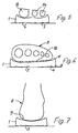
- depressions 3, 4, 5, 6 and 7 are arranged along those underside regions of the sole 1, through which an imaginary line of greatest pressure load runs when the foot 8 rolls, the recess 3 in the region the heel 9 (see FIGS. 1 and 7) and the depression 4 are arranged closer to this outer edge 11 along the outer edge 11 running from the heel area to the ball 10 outside the center of the sole 1.
- the depression 5 is located in the area of the ball of the foot 12 (FIGS. 1 and 6), this depression 5 extending from the outer ball to the inner ball.
- the depressions 6 and 7 are arranged in the region of the toes 13 and 14.
- the foot rolls over the heel 9, the outer edge, the ball 12 and the toes 13 and 14, so that in the course of this rolling the sole 1 according to FIGS. 7 to 5 in each case in the region of the depressions yields at the bottom and is deformed, so that practically an appropriate foot bed is created again and again practically during the rolling of the foot at each load point.
- a non-recessed sole area 15 as a support area. If necessary, a less pronounced depression could also be provided in this area.
- This non-recessed sole area 15 aids in guiding and stabilizing the foot during the walking or running process, in particular to prevent it from kinking to the side.
- a non-recessed sole area 16 runs as a support for the depression located on the foot 12 between the balls 12 and toes 13 and 14.
- the sole 1 does not yield on its upper side in this area, so that the toes find a desired support on the bead that then arises when they press themselves deeper into the upper side of the sole due to the depressions 6 and 7 on the underside.
- the depths of the recesses 3 to 7 differ depending on the pressure load to be expected and that in the area of larger pressure loads a deeper recess is provided.
- a deeper depression is provided in the area of the heel 9, in the area of the inner ball and in the area of the big toe 13 than in the other deepened areas, thereby, on the one hand, the greater pressure load mentioned at these points when the foot rolls off and also any stronger ones Expression of the bottom of the foot is taken into account.
- the larger depressions allow a correspondingly greater yield under the greater pressure load until the surface of the underside of the sole in the depression contacts the floor or subsoil.
- the depth of the recesses 3 to 7 is expediently chosen so that at least the central region of the recess is deformable under load up to the level region of the non-recessed surface of the underside 2 of the sole 1.
- This also surprisingly and effectively results in the fact that, in the event of a load, the respectively loaded sole area can rest practically over the entire surface of the ground, although depressions are provided. Accordingly. It can be advantageous if the underside 2 of the sole 1 and also the surfaces of the depressions 3 to 7 are fully or partially profiled, since they can also come into contact with the ground and the contact with the ground can be improved by the profiling.
- the transitions from the outer surface of the underside 2 of the sole 1 to the inner region of the depressions 3 to 7 are graded. However, these transitions could also be fluid and smooth.
- the individual stages 17 are each approximately the same size, while the greater depth of some wells is achieved by a correspondingly increased number of such stages 17. It can be seen in the drawings that in the area of the heel 9 and the area of the inner ball and also in the area of the big toe 13 there are two gradations 17 and in the other areas a gradation 17 for forming the depressions.
- the greatest depth dimension of the depressions can be about 3 mm.
- the dimension of each step 17 can be about 1/2 to 1 1/2 mm, in particular about 3/4 or 4 / 5mm or 1 mm.
- a variant can also consist in the fact that the first area of the deeper depressions and / or the shallower depressions have transitions flowing from the surface of the underside 2 of the sole 1 and the deeper areas of the depressions are stepped or it could be provided the other way round, that first a first level of depth is generated via a step 17, while from there even deeper areas can be reached via flowing transitions.
- FIG. 1 An important feature can also be seen in FIG. 1, namely that all depressions 3 to 7 of the underside 2 towards the sole edge are each delimited by a non-recessed area of the underside 2 of the sole 1.
- the recess 18 arranged on the inner joint and not belonging to the invention there is therefore not a single recess which is open at the edge and which, under load, could cause the sole to tip over in this recess region.
- the advantage of the great sure-footedness of a flat or flat sole on the underside is maintained despite the depressions according to the invention along the main stress lines when rolling off.
- the sole according to the invention is suitable for leisure, gymnastic and sports shoes, possibly with a small heel height up to a negative heel.
- Fig. 1 it is also provided that the recess 4 and the recess 5 are connected without interruption in the region of the outer bale.
- the depression 4 thus merges into the depression 5, even if the depression then gains a greater depth in the region of the inner ball.
- 1 and 8 and the associated cross-sections indicate that the depth of the heel depression 3, the inner ball depression 5 and / or the depression 6 for the big toe is greater than that of the depressions 4 and 7 corresponding to the outside of the foot . This corresponds, albeit on the side facing away from the foot itself, to the anatomy of the foot and the size of the pressure load which occurs when it rolls off.
- these non-recessed surfaces 15, 16 and 19 of the underside 2 can be profiled in order to increase the grip of the sole 1.
- these inner surfaces can also be provided with such a profile that increases the grip.
Abstract
Description
Die Erfindung betrifft eine Schuh- oder Laufsohle mit im wesentlichen ebener oder planer, jedoch bereichsweise vertiefter Unterseite aus druck-und/oder biegeelastischem Werkstoff mit Vertiefungen im Fersenbereich und im Ballenbereich.The invention relates to a shoe or outsole with a substantially flat or planar, but partially deepened lower surface made of pressure and / or flexurally elastic material with depressions in the heel area and in the ball area.
Derartige Sohlen sind in vielfältiger Form bekannt.Such soles are known in many forms.
Aus der DE-A 1 485 580 ist beispielsweise eine Sohle für einen Sportschuh bekannt, die im Fersenbereich eine Vertiefung hat. Dadurch soll die Dämpfung in diesem Bereich bei bleichzeitig guter Standsicherheit vergrößert werden. Demgemäß läuft um die Vertiefung ein breiter Rand um, der die Ferse bei Sprüngen oder starkem Aufprall schützen soll.From DE-A 1 485 580, for example, a sole for a sports shoe is known which has a depression in the heel area. This is intended to increase the damping in this area while maintaining good stability at the same time. Accordingly, a wide edge runs around the depression, which is intended to protect the heel in the event of jumps or strong impacts.
Auch aus der US-A 4 494 321 ist eine Sohlenkonstruktion mit Ausnehmung bzw. Vertiefung im Fersenbereich und im Ballenbereich bekannt, um eine gute Dämpfung zu erzielen.From US-A 4,494,321 a sole construction with a recess or depression in the heel area and in the ball area is known in order to achieve good cushioning.
Aus der DE-A 2 752 300 ist eine Vertiefung des hinteren Absatzbereiches in Form einer Abschrägung mit gekrümmtem Querschnitt bekannt, um das Abrollverhalten beim ersten Aufsetzen des Fußes zu verbessern.DE-A 2 752 300 discloses a depression in the rear heel area in the form of a bevel with a curved cross section in order to improve the rolling behavior when the foot is first put on.
Für eine möglichst bequeme und gute Unterstützung des Fußes während des Gehens in der weiteren Abrollphase hat man sich bisher auf die Ausgestaltung des Fußbettes an der Oberseite der Sohle konzentriert. Dies bewirkt jedoch vor allem bei fabrikmäßiger Vorfertigung, daß die im Prinzip jeweils verschiedenen Füße nur unvollkommen zu einem solchen Fußbett passen und häufig durch ausgeprägte Fußbetten eingeengt oder sogar ungünstig abgestützt werden.For the most comfortable and good support of the foot while walking in the further rolling phase, the focus has so far been on the design of the footbed on the top of the sole. However, especially in the case of factory prefabrication, this has the effect that the feet, which in principle differ in each case, only fit incompletely with such a footbed and are frequently narrowed or even unfavorably supported by pronounced footbeds.
Es besteht deshalb die Aufgabe, eine Sohle der eingangs erwähnten Art zu schaffen, bei welcher der Fuß beim Abrollen entsprechend den auftretenden Belastungen jeweils gut abgestützt wird, ohne durch ein Fußbett beengt zu werden.It is therefore the task of creating a sole of the type mentioned in the introduction, in which the foot is well supported when rolling in accordance with the loads that occur, without being constricted by a footbed.
Die Lösung dieser Aufgabe erfolgt mit den Maßnahmen des kennzeichnenden Teiles des Patentanspruches 1.This object is achieved with the measures of the characterizing part of
Durch diese Maßnahmen wird die gesamte Laufsohlen-Unterseite in den Fuß entlastenden Komfort beim Gehen oder Laufen einbezogen. Entsprechend dem Barfußlaufen auf weichem Boden kann sich der Fuß in dem Schuh in die Sohle jeweils dort stärker eindrücken, wo der beim Abrollen eine entsprechend größere Belastung erfährt, selbst wenn auf harten Böden gelaufen wird. Dies wird aufgrund des weichen und elastischen Sohlenmateriales in Verbindung mit den entsprechenden Vertiefungen an der Sohlenunterseite gemäß der vorliegenden Erfindung ermöglicht. Somit genügt ein nur schwach ausgebildetes Fußbett oder gegebenenfalls ist sogar gar kein Fußbett erforderlich, um dem Fuß dennoch während des Laufens durch die aufgrund der Vertiefungen möglichen Reaktionen und Verformungen an der Sohle jeweils eine bestmögliche Anpassung und Unterstützung zu vermitteln. Praktisch kann sich der Fuß aufgrund der erfindungsgemäßen Sohlenform beim Laufen sein Fußbett jeweils immer wieder neu formen und in die Sohle eindrücken. Somit werden auch unterschiedlich geformte Füße von der erfindungsgemäßen Sohle beim Gehen und Abrollen bestmöglich unterstützt.Through these measures, the entire bottom of the outsole is incorporated into the comfort that relieves the foot when walking or running. Corresponding to walking barefoot on soft ground, the foot in the shoe can push itself into the sole more strongly where it experiences a correspondingly greater load when rolling off, even when walking on hard floors. This is made possible due to the soft and elastic sole material in connection with the corresponding depressions on the underside of the sole according to the present invention. A footbed that is only weakly formed, or even a footbed may not be necessary at all, in order to provide the foot with the best possible adaptation and support during the walk due to the reactions and deformations on the sole that are possible due to the depressions. In practice, due to the shape of the sole according to the invention, the foot can always reshape its footbed and press it into the sole. Thus, differently shaped feet are optimally supported by the sole according to the invention when walking and rolling.
Ausgestaltungen der Erfindung und insbesondere der Anordnung und Zuordnung der Vertiefungen zueinander sowie auch der Abmessungen der Vertiefungen zur guten Abstützung des Fußes bei gleichzeitig guter Anpaßbarkeit sind Gegenstand der Ansprüche 2 bis 17 und 19.Embodiments of the invention and in particular the arrangement and assignment of the depressions to one another and also the dimensions of the depressions for good support of the foot with at the same time good adaptability are the subject of
Es sei erwähnt, daß selbstverständlich die nicht vertieften Flächen der Unterseite auch profiliert sein können, um die Griffigkeit der Sohle zu erhöhen. Die bei einer solchen Profilierung notgedrungen vorhandenen Niveauunterschiede gelten jedoch nicht als Vertiefungen im Sinne der vorliegenden Erfindung, die ihrerseits ähnlich einem Fußbett, jedoch auf der dem Fuß abgewandten Seite der Sohle ausgebildet sind.It should be mentioned that the non-recessed surfaces of the underside can of course also be profiled in order to increase the grip of the sole. However, the level differences which are inevitable with such a profiling do not count as depressions in the sense of the present invention, which in turn are formed like a footbed, but on the side of the sole facing away from the foot.
Vor allem bei Kombination einzelner oder mehrerer der in den Ansprüchen 1 bis 19 enthaltenen Merkmale und Maßnahmen ergibt sich eine einfach herstellbare Schuh- oder Laufsohle, die ohne oder mit nur geringer Fußbettung auf der dem Fuß zugewandten Seite dennoch eine optimale Unterstützung und Anpassung an die Fußunterseite ermöglicht, wobei aber dennoch eine gute Abstützung des Fußes vor allem auch an den Seitenrändern gegeben ist, so daß sich der Fuß in einem Schuh, einer Sandale oder dergleichen mit der erfindungsgemäßen Sohle ausgestatteten Schuhwerk an seine Unterstützung etwa so anpassen kann wie beim Barfußlaufen auf Sand oder weichem Boden, wobei aber zusätzlich eine seitliche Abstützung durch den die Vertiefungen begrenzenden Sohlenrand erzielt wird, die ein besser geführtes Gehen oder Laufen und eine Verminderung der Gefahr eines Umknickens bedeutet. Darüberhinaus kann der Verschleiß der Unterseite der Sohle durch Anpassung an die Abmessungen der Vertiefungen vergleichmäßigt werden.Especially when combining one or more of the features and measures contained in
Nachstehend ist die Erfindung mit ihren ihr als wesentlich zugehörenden Einzelheiten anhand der Zeichnung noch näher beschrieben.The invention is described in more detail below with its details that are essential to it, using the drawing.
Es zeigt in schematisierter Darstellung:
- Fig. 1 eine Ansicht auf die Unterseite der erfindungsgemäßen Sohle und die dort vorgesehenen Vertiefungen,
- Fig. 2 einen Querschnitt der Sohle im Zehenbereich gemäß der Linie II-II in Fig. 1,
- Fig. 3 einen Querschnitt der Sohle im Ballenbereich gemäß der Linie III-III,
- Fig. 4 einen Querschnitt der Sohle im Fersenbereich gemäß der Linie IV-IV in Fig. 1,
- Fig. 5 den Querschnitt der Sohle im Zehenbereich gemäß Fig. 2 unter Belastung,
- Fig. 6 den Querschnitt der Sohle im Ballenbereich gemäß Fig. 3, jedoch unter Belastung,
- Fig. 7 den Querschnitt der Sohle im Fersenbereich gemäß Fig. 4 unter Belastung,
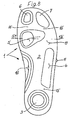
- Fig. 8 eine Ansicht auf die Unterseite einer abgewandelten Ausführungsform der erfindungsgemäßen Sohle,
- Fig. 9 einen Querschnitt der Sohle im Ballenbereich gem. der Schnittlinie IX-IX in Fig. 8 sowie
- Fig. 10 den Querschnitt der Sohle gemäß Fig.9, jedoch unter Belastung.
- 1 is a view of the underside of the sole according to the invention and the depressions provided there,
- 2 shows a cross section of the sole in the toe area along the line II-II in FIG. 1,
- 3 shows a cross section of the sole in the ball area along the line III-III,
- 4 shows a cross section of the sole in the heel area along the line IV-IV in FIG. 1,
- 5 shows the cross section of the sole in the toe area according to FIG. 2 under load,
- 6 shows the cross section of the sole in the ball area according to FIG. 3, but under load,
- 7 shows the cross section of the sole in the heel area according to FIG. 4 under load,
- 8 is a view of the underside of a modified embodiment of the sole according to the invention,
- Fig. 9 shows a cross section of the sole in the ball area acc. the section line IX-IX in Fig. 8 and
- 10 shows the cross section of the sole according to FIG. 9, but under load.
Eine im ganzen mit 1 bezeichnete Schuh- oder Laufsohle, im folgenden auch kurz Sohle 1 genannt, hat eine im wesentlichen ebene oder plane Unterseite 2, die jedoch mit noch näher zu beschreibenden Vertiefungen versehen ist und aus druck-und/oder biegeelastischem Werkstoff besteht, also unter Belastung nachgiebig ist.A shoe sole or outsole, generally designated 1, hereinafter also referred to as sole 1, has an essentially flat or
Vor allem in Fig. 1 erkennt man, daß Vertiefungen 3,4,5, 6 und 7 entlang denjenigen unterseitigen Bereichen der Sohle 1 angeordnet sind, durch welche eine gedachte Linie größter Druckbelastung beim Abrollen des Fußes 8 verläuft, wobei die Vertiefung 3 im Bereich der Ferse 9 (vgl. Fig. 1 und 7) und die Vertiefung 4 entlang dem vom Fersenbereich zu den Ballen 10 verlaufenden Außenrand 11 außerhalb der Mitte der Sohle 1 näher zu diesem Außenrand 11 angeordnet sind. Die Vertiefung 5 befindet sich im Bereich des Fußballens 12 (Fig. 1 und Fig. 6) wobei diese Vertiefung 5 vom Außenballen bis zum Innenballen reicht. Schließlich sind im Bereich der Zehen 13 und 14 die Vertiefungen 6 und 7 angeordnet.Especially in Fig. 1 it can be seen that
Genau in der vorbeschriebenen Reihenfolge erfolgt das Abrollen des Fußes über die Ferse 9, den Außenrand, den Ballen 12 und die Zehen 13 und 14, so daß im Verlaufe dieses Abrollens die Sohle 1 gemäß den Fig.7 bis 5 jeweils im Bereich der Vertiefungen nach unten nachgibt und verformt wird, so daß praktisch während des Abrollens des Fußes an jeder Belastungsstelle eine entsprechende Fußbettung immer wieder neu erzeugt wird.Exactly in the order described above, the foot rolls over the
In Fig. 1 erkennt man, daß die Vertiefung 3 im Bereich der Ferse 9 von der benachbarten Vertiefung 4 des Außenrandes 11 durch einen nicht vertieften Sohlenbereich 15 als Stützbereich getrennt ist. Gegebenenfalls könnte in diesem Bereich aber auch eine weniger ausgeprägte Vertiefung vorgesehen sein. Dieser nicht vertiefte Sohlenbereich 15 hilft bei der Führung und Stabilisierung des Fußes während des Geh- oder Laufvorganges, um vor allem ein seitliches Abknicken zu verhindern.1 that the
Die Vertiefungen 4 und 5 des Außenrandes 11 und der Fußballen 12 gehen im Ausführungsbeispiel ohne Unterbrechung ineinander über, so daß in dieser Abrollphase, bei welcher die Hauptbelastung von der Außenseite zur Innenseite überwechselt, ein entsprechend ununterbrochener Übergang bei der Anpassung der Sohle 1 gewährleistet ist.The
Zwischen der Vertiefung 5 des Bereiches des Ballens 12 und den Vertiefungen 6 und 7 im Zehenbereich verläuft wiederum ein nicht vertiefter Sohlenbereich 16 als Abstützung der am Fuß 12 zwischen Ballen 12 und Zehen 13 und 14 befindlichen Vertiefung. Beim Abrollen wird an diesem Bereich die Sohle 1 an ihrer Oberseite nicht nachgeben, so daß die Zehen sich an dem dann entstehenden Wulst, wenn sie selbst sich aufgrund der unterseitigen Vertiefungen 6 und 7 tiefer in die Sohlenoberseite eindrücken, eine gewünschte Abstützung finden.Between the
Dabei erkennt man in Fig. 1 ferner, daß im Bereich der Zehen 13 und 14 zwei voneinander getrennte Vertiefungen 6 und 7 vorgesehen sind, wobei die eine Vertiefung 6 im Bereich der großen Zehe 13 und die andere Vertiefung 7 im Bereich der übrigen Zehen-Beeren angeordnet ist. Dadurch wird berücksichtigt, daß die große Zehe beim Abrollen häufig einer stärkeren Belastung als die übrigen Zehen ausgesetzt ist bzw. sich die Belastung einigermaßen gleichmäßig auf die große Zehe einerseits und die übrigen Zehen andererseits aufteilt. Dabei ist es außerdem wünschenswert für die Führung des Fußes, wenn zwischen der großen und den übrigen Zehen eine gewisse Abstützung und Führung gegeben ist, die durch die gewählte Anordnung der Vertiefungen bei der Belastung wiederum dadurch entsteht, daß im Bereich der Vertiefungen die gegenüberliegende Oberseite der Sohle 1 nachgibt, während sie an den nicht ausgenommenen oder vertieften Bereichen nicht oder nur weniger nachgibt.1 that two
Insgesamt wird praktisch durch die Anordnung der Vertiefungen auf der Unterseite, die in gewissem Sinne ähnlich wie bei einer Fußbettung angeordnet und orientiert sind, erreicht, daß die gegenüberliegende Seite jeweils bei Belastung eine entsprechende Fußbettung kurzzeitig ausbildet.Overall, it is practically achieved by the arrangement of the depressions on the underside, which are arranged and oriented in a manner similar to a footbed that the opposite side briefly forms a corresponding footbed under load.
Vor allem anhand der Fig. 2 bis 4 erkennt man, daß die Vertiefungen 3 bis 7 bezüglich ihrer Tiefe je nach zu erwartender Druckbelastung verschieden sind und im Bereich größerer Druckbelastungen jeweils eine tiefere Vertiefung vorgesehen ist. Dabei ist im Bereich der Ferse 9, im Bereich des Innenballens und im Bereich der großen Zehe 13 jeweils eine tiefere Vertiefung vorgesehen als in den übrigen vertieften Bereichen, wobei dadurch einerseits der erwähnten größeren Druckbelastung an diesen Stellen beim Abrollen des Fußes und auch der eventuellen stärkeren Ausprägung der Fußunterseite Rechnung getragen wird.Especially from FIGS. 2 to 4 it can be seen that the depths of the
Die größeren Vertiefungen erlauben bei der größeren Druckbelastung ein entsprechend stärkeres Nachgeben, bis die in der Vertiefung befindliche Oberfläche der Sohlenunterseite Kontakt mit dem begangenen Boden oder Untergrund erhält.The larger depressions allow a correspondingly greater yield under the greater pressure load until the surface of the underside of the sole in the depression contacts the floor or subsoil.
In den Fig. 5 bis 7 ist dabei angedeutet, daß die Tiefe der Vertiefungen 3 bis 7 zweckmäßigerweise so gewählt ist, daß wenigstens der mittlere Bereich der Vertiefung bei Belastung bis in den Niveaubereich der nicht vertieften Oberfläche der Unterseite 2 der Sohle 1 verformbar ist. Dadurch ergibt sich in überraschender und effektvoller Weise zusätzlich, daß im Belastungsfalle der jeweils belastete Sohlenbereich praktisch ganzflächig am Untergrund aufliegen kann, obwohl Vertiefungen vorgesehen sind. Demgem. kann es vorteilhaft sein, wenn die Unterseite 2 der Sohle 1 und auch die Oberflächen der Vertiefungen 3 bis 7 ganz oder teilweise profiliert sind, da sie ebenfalls mit dem Untergrund in Kontakt kommen können und durch die Profilierung der Bodenkontakt verbessert sein kann.5 to 7 it is indicated that the depth of the
In den dargestellten Ausführungsbeispielen sind die Übergänge von der äußeren Oberfläche der Unterseite 2 der Sohle 1 zu dem Innenbereich der Vertiefungen 3 bis 7 abgestuft. Diese Übergänge könnten aber auch fließend und stufenlos sein. Bei den gewählten abgestuften Übergängen sind die einzelnen Stufen 17 jeweils etwa gleich groß, während die größere Tiefe mancher Vertiefungen durch eine entsprechend vergrößerte Anzahl solcher Stufen 17 erreicht wird. Man erkennt in den Zeichnungen, daß im Bereich der Ferse 9 und dem Bereich des Innenballens sowie auch im Bereich der großen Zehe 13 jeweils zwei Abstufungen 17 und in den übrigen Bereichen eine Abstufung 17 zur Bildung der Vertiefungen vorgesehen sind. Dabei kann das größte Tiefenmaß der Vertiefungen etwa 3 mm betragen. Die Abmessung jeder Stufung 17 kann etwa 1/2 bis 1 1/2 mm, insbesondere etwa 3/4 oder 4/5mm oder 1 mm betragen.In the exemplary embodiments shown, the transitions from the outer surface of the
Eine nicht dargestellte Variante kann auch darin bestehen, daß der erste Bereich der tieferen Vertiefungen und/oder die flacheren Vertiefungen von der Oberfläche der Unterseite 2 der Sohle 1 ausgehend fließende Übergänge haben und die tieferen Bereiche der Vertiefungen abgestuft sind oder es könnte umgekehrt vorgesehen sein, daß zunächst ein erstes Vertiefungsniveau über eine Stufe 17 erzeugt ist, während von da aus noch tiefere Bereiche über fliessende Übergänge erreicht werden.A variant (not shown) can also consist in the fact that the first area of the deeper depressions and / or the shallower depressions have transitions flowing from the surface of the
In den Fig. 1 ist noch ein wichtiges Merkmal zu erkennen, wonach nämlich alle Vertiefungen 3 bis 7 der Unterseite 2 zum Sohlenrand hin jeweils von einem nicht vertieften Bereich der Unterseite 2 der Sohle 1 begrenzt sind. Abgesehen von der am Innengelenk angeordneten, nicht zur Erfindung gehörenden Vertiefung 18 ist also keine einzige randoffene Vertiefung vorgesehen, die bei Belastung zu einem Abkippen der Sohle in diesem Vertiefungsbereich führen könnte. Vielmehr wird der Vorteil der großen Trittsicherheit einer an der Unterseite planen oder ebenen Sohle trotz der erfindungsgemä-Ben Vertiefungen entlang den Haupt belastungslinien beim Abrollen beibehalten. Die erfindungsgemäße Sohle eignet sich aufgrund der vorteilhaften Anpassung an die Fußform für Freizeit-, Gymnastik- und Sportschuhe gegebenenfalls mit geringer Absatzhöhe bis hin zum Negativabsatz.An important feature can also be seen in FIG. 1, namely that all
In Fig. 1 ist ferner vorgesehen, daß die Vertiefung 4 und die Vertiefung 5 ohne Unterbrechung im Bereich des Außenballens verbunden sind. Die Vertiefung 4 geht also in die Vertiefung 5 über, wenngleich im Bereich des Innenballens dann die Vertiefung noch einmal eine größere Tiefe gewinnt. Dabei ist in Fig.1 und 8 und den zugehörigen Querschnitten angedeutet, daß die Tiefe der Fersen-Vertiefung 3, der Innenballen-Vertiefung 5 und/oder der Vertiefung 6 für die große Zehe größer als die der der Fußaußenseite entsprechenden Vertiefungen 4 und 7 ist. Dies entspricht, wenn auch auf der dem Fuß selbst abgekehrten Seite der Anatomie des Fußes und der Größe der beim Abrollen auftretenden Druckbelastung.In Fig. 1 it is also provided that the
In Fig. 8 bis 10 ist eine abgewandelte Ausführungsform dargestellt, bei welcher die Vertiefung 4 in Abrollbewegungsrichtung vor dem Bereich der Vertiefung 5 für die Ballen endet und zwischen der Vertiefung 4 und der Vertiefung 5 eine auf dem Niveau der Sohlenunterseite 2 befindliche, ggf. eine die Griffigkeit der Sohle 1 erhöhende Profilierung aufweisende Stützzone 19 vorgesehen ist. Deren Aufgabe entspricht somit weitgehend der der Sohlenbereiche 15 und 16.8 to 10 a modified embodiment is shown, in which the
Im übrigen entspricht diese Ausführungsform der gem. den Figuren 1 bis 7, weshalb auch übereinstimmende Bezugszeichen für übereinstimmende Vertiefungen und Sohlenbereiche vorgesehen sind, die somit einer zusätzlichen Beschreibung nicht bedürfen.Otherwise, this embodiment corresponds to the gem. Figures 1 to 7, which is why matching reference numerals are provided for matching depressions and sole areas, which therefore do not require an additional description.
Es sei noch erwähnt, daß diese nicht vertieften Flächen 15,16 und 19 der Unterseite 2 profiliert sein können, um die Griffigkeit der Sohle 1 zu erhöhen. Da aber auch die Innenflächen der Vertiefungen gemäß den Fig.5 bis 7 und 10 unter Druckbelastung Bodenkontakt erhalten können, können ggf. auch diese Innenflächen mit einer solchen die Griffigkeit erhöhenden Profilierung versehen sein.It should also be mentioned that these
Claims (19)
Priority Applications (1)
| Application Number | Priority Date | Filing Date | Title |
|---|---|---|---|
| AT86100431T ATE50123T1 (en) | 1985-08-03 | 1986-01-15 | SHOE OR OUTSOLE. |
Applications Claiming Priority (2)
| Application Number | Priority Date | Filing Date | Title |
|---|---|---|---|
| DE3527938 | 1985-08-03 | ||
| DE19853527938 DE3527938A1 (en) | 1985-08-03 | 1985-08-03 | SHOE OR OUTSOLE |
Publications (3)
| Publication Number | Publication Date |
|---|---|
| EP0213257A2 EP0213257A2 (en) | 1987-03-11 |
| EP0213257A3 EP0213257A3 (en) | 1987-11-25 |
| EP0213257B1 true EP0213257B1 (en) | 1990-02-07 |
Family
ID=6277648
Family Applications (1)
| Application Number | Title | Priority Date | Filing Date |
|---|---|---|---|
| EP86100431A Expired - Lifetime EP0213257B1 (en) | 1985-08-03 | 1986-01-15 | Shoe sole |
Country Status (5)
| Country | Link |
|---|---|
| US (1) | US4697361A (en) |
| EP (1) | EP0213257B1 (en) |
| AT (1) | ATE50123T1 (en) |
| CA (1) | CA1257472A (en) |
| DE (2) | DE3527938A1 (en) |
Cited By (14)
| Publication number | Priority date | Publication date | Assignee | Title |
|---|---|---|---|---|
| US6308439B1 (en) | 1989-08-30 | 2001-10-30 | Anatomic Research, Inc. | Shoe sole structures |
| US6360453B1 (en) | 1989-10-03 | 2002-03-26 | Anatomic Research, Inc. | Corrective shoe sole structures using a contour greater than the theoretically ideal stability plan |
| US6487795B1 (en) | 1990-01-10 | 2002-12-03 | Anatomic Research, Inc. | Shoe sole structures |
| US6662470B2 (en) | 1989-08-30 | 2003-12-16 | Anatomic Research, Inc. | Shoes sole structures |
| US6668470B2 (en) | 1988-09-02 | 2003-12-30 | Anatomic Research, Inc. | Shoe sole with rounded inner and outer side surfaces |
| US6675498B1 (en) | 1988-07-15 | 2004-01-13 | Anatomic Research, Inc. | Shoe sole structures |
| US6708424B1 (en) | 1988-07-15 | 2004-03-23 | Anatomic Research, Inc. | Shoe with naturally contoured sole |
| US6789331B1 (en) | 1989-10-03 | 2004-09-14 | Anatomic Research, Inc. | Shoes sole structures |
| US7647710B2 (en) | 1992-08-10 | 2010-01-19 | Anatomic Research, Inc. | Shoe sole structures |
| US8141276B2 (en) | 2004-11-22 | 2012-03-27 | Frampton E. Ellis | Devices with an internal flexibility slit, including for footwear |
| US8256147B2 (en) | 2004-11-22 | 2012-09-04 | Frampton E. Eliis | Devices with internal flexibility sipes, including siped chambers for footwear |
| US8291618B2 (en) | 2004-11-22 | 2012-10-23 | Frampton E. Ellis | Devices with internal flexibility sipes, including siped chambers for footwear |
| US8670246B2 (en) | 2007-11-21 | 2014-03-11 | Frampton E. Ellis | Computers including an undiced semiconductor wafer with Faraday Cages and internal flexibility sipes |
| US8732230B2 (en) | 1996-11-29 | 2014-05-20 | Frampton Erroll Ellis, Iii | Computers and microchips with a side protected by an internal hardware firewall and an unprotected side connected to a network |
Families Citing this family (57)
| Publication number | Priority date | Publication date | Assignee | Title |
|---|---|---|---|---|
| FR2610797B1 (en) * | 1987-02-12 | 1989-05-12 | Salomon Sa | ALPINE SKI BOOT WITH SOLE PROVIDED WITH A SHOCK ABSORBER |
| DK157387C (en) * | 1987-12-08 | 1990-06-05 | Eccolet Sko As | shoe sole |
| CA1340997C (en) * | 1988-07-15 | 2000-05-16 | Frampton E. Ellis Iii | Shoe with naturally contoured sole |
| US4866860A (en) * | 1988-07-25 | 1989-09-19 | Wolverine World Wide, Inc. | Metatarsal head shoe cushion construction |
| US6314662B1 (en) | 1988-09-02 | 2001-11-13 | Anatomic Research, Inc. | Shoe sole with rounded inner and outer side surfaces |
| DE3903743A1 (en) * | 1989-02-09 | 1990-08-16 | Friedrich Hackner | Foot bed for shoes |
| AT402467B (en) * | 1989-11-24 | 1997-05-26 | Vital Schuhe Gmbh | SHOE SOLE WITH A FOOTBED |
| US5005299A (en) * | 1990-02-12 | 1991-04-09 | Whatley Ian H | Shock absorbing outsole for footwear |
| CA2051230C (en) * | 1991-09-12 | 1997-11-18 | Robert Burke | Power midsole cushioning and stability concept |
| US5440826A (en) * | 1992-04-08 | 1995-08-15 | Whatley; Ian H. | Shock absorbing outsole for footwear |
| CA2070274C (en) * | 1992-06-02 | 1997-02-11 | Robert Garfield Burke | Shoe insole for foot rehabilitation |
| US5375346A (en) * | 1993-04-02 | 1994-12-27 | Energaire Corporation | Thrust producing shoe sole and heel improved stability |
| DE69430922T2 (en) | 1993-12-13 | 2002-11-14 | Donald L Minges | CONTACT SURFACE WITH NATURAL IMPRESSION |
| US7101604B1 (en) | 1995-09-05 | 2006-09-05 | Minges Donald L | Footwear sole having a natural grip |
| US5653046A (en) * | 1995-09-06 | 1997-08-05 | Lawlor; Kevin B. | Durable, lightweight shock resistant shoe sole |
| US6854198B2 (en) * | 1996-05-29 | 2005-02-15 | Jeffrey S. Brooks, Inc. | Footwear |
| US5930916A (en) * | 1996-06-14 | 1999-08-03 | Connor; Dennis J. | Insoles liners and footwear incorporating loofah material |
| US5927567A (en) * | 1996-11-12 | 1999-07-27 | Owens-Illinois Closure Inc. | Dispensing closure and method of making |
| US5862614A (en) * | 1997-01-31 | 1999-01-26 | Nine West Group, Inc. | Indoor exercise shoe and sole therefor |
| US6312361B1 (en) * | 1997-04-16 | 2001-11-06 | Kenneth Scott Hayes | Synthetic sand frontal training shoe |
| AU4938299A (en) * | 1998-06-30 | 2000-01-17 | Evgeniy Vladimirovich Grishin | Inner sole for shoes and variants |
| DE10218987A1 (en) | 2002-04-24 | 2003-11-06 | Hans Seiter | Shoe insole for diabetics |
| WO2009097589A1 (en) | 2008-01-31 | 2009-08-06 | Jeffrey David Stewart | Exercise apparatuses and methods of using the same |
| US9055781B2 (en) * | 2009-10-08 | 2015-06-16 | Varithotics Co., Ltd. | Body balance device |
| US20130185955A1 (en) * | 2012-01-19 | 2013-07-25 | Hsien-Hsiung Cheng | Ergonomic footwear |
| US9247784B2 (en) | 2012-06-22 | 2016-02-02 | Jeffrey David Stewart | Wearable exercise apparatuses |
| USD762053S1 (en) * | 2013-06-21 | 2016-07-26 | Tsuyoshi Takahashi | Footwear insole |
| DE202013103808U1 (en) * | 2013-08-22 | 2013-11-15 | Christian Lenthe | Forefoot cushion, computer program product for custom fabrication of the forefoot cushion |
| US9204687B1 (en) * | 2014-07-24 | 2015-12-08 | Shlomo Piontkowski | Footwear with dynamic arch system |
| US10827798B2 (en) | 2014-07-24 | 2020-11-10 | Shlomo Piontkowski | Footwear with dynamic arch system |
| US9857788B2 (en) | 2014-07-24 | 2018-01-02 | Shlomo Piontkowski | Adjustable height sole |
| US10058144B2 (en) * | 2014-08-06 | 2018-08-28 | Nike, Inc. | Article of footwear with midsole with arcuate underside cavity |
| USD791456S1 (en) * | 2014-11-18 | 2017-07-11 | Peacocks Orthotics Limited | Insole |
| USD753908S1 (en) * | 2015-01-08 | 2016-04-19 | Vcg Holdings Ltd. | Footwear insert |
| USD762367S1 (en) * | 2015-06-25 | 2016-08-02 | Spenco Medical Corporation | Shoe insole |
| USD762368S1 (en) * | 2015-06-25 | 2016-08-02 | Spenco Medical Corporation | Shoe insole |
| USD761543S1 (en) * | 2015-06-25 | 2016-07-19 | Spenco Medical Corporation | Shoe insole |
| USD762366S1 (en) * | 2015-06-25 | 2016-08-02 | Spenco Medical Corporation | Shoe insole |
| US10212988B2 (en) * | 2015-12-01 | 2019-02-26 | Nike, Inc. | Articles of footwear and sole structures for articles of footwear |
| USD812877S1 (en) | 2016-05-13 | 2018-03-20 | Nike, Inc. | Shoe sole |
| US11039659B2 (en) * | 2017-09-07 | 2021-06-22 | Nike, Inc. | Sole structure for article of footwear |
| USD852478S1 (en) * | 2017-09-21 | 2019-07-02 | Nike, Inc. | Shoe outsole |
| USD851881S1 (en) * | 2017-09-21 | 2019-06-25 | Nike, Inc. | Shoe outsole |
| USD849377S1 (en) * | 2017-10-25 | 2019-05-28 | Nike, Inc. | Shoe outsole |
| USD848717S1 (en) * | 2017-10-25 | 2019-05-21 | Nike, Inc. | Shoe outsole |
| USD849378S1 (en) * | 2017-10-25 | 2019-05-28 | Nike, Inc. | Shoe outsole |
| USD854294S1 (en) * | 2018-03-01 | 2019-07-23 | Nike, Inc. | Shoe |
| USD854298S1 (en) * | 2018-03-16 | 2019-07-23 | Nike, Inc. | Shoe |
| USD844308S1 (en) * | 2018-08-03 | 2019-04-02 | Nike, Inc. | Shoe |
| USD846249S1 (en) * | 2018-08-09 | 2019-04-23 | Nike, Inc. | Shoe |
| US11419384B2 (en) | 2019-02-07 | 2022-08-23 | Benjamin Ari Bryer | Shoe for simulating exercising on natural granular matertial |
| USD901867S1 (en) * | 2019-04-16 | 2020-11-17 | Tk In So Les Ltd. | Insole |
| USD908331S1 (en) * | 2019-07-11 | 2021-01-26 | Nike, Inc. | Shoe |
| USD912955S1 (en) * | 2019-08-29 | 2021-03-16 | Nike, Inc. | Shoe |
| USD929092S1 (en) * | 2020-01-23 | 2021-08-31 | Asics Corporation | Shoe |
| USD910996S1 (en) * | 2020-07-08 | 2021-02-23 | Nike, Inc. | Shoe |
| USD1014942S1 (en) * | 2020-10-12 | 2024-02-20 | Henan Bangni Biological Engineering Co., Ltd. | Insole |
Family Cites Families (18)
| Publication number | Priority date | Publication date | Assignee | Title |
|---|---|---|---|---|
| GB149599A (en) * | 1920-04-08 | 1920-08-19 | John Peachey Crouch | Improvements in rubber soles and heels for boots, shoes, and the like |
| FR584489A (en) * | 1924-03-08 | 1925-02-07 | Removable or fixed sole of the shoe for fine sands | |
| US2424463A (en) * | 1945-06-09 | 1947-07-22 | Hogg Elsie Claire | Multiple antiskid ribbed suction sole for shoes and rubber footwear |
| DE1708672U (en) * | 1955-06-23 | 1955-10-13 | Ingo Streblow | HEELLESS SHOE SOLE MADE OF ELASTIC FABRIC, E.G. CREPE RUBBER. |
| US3086532A (en) * | 1961-09-13 | 1963-04-23 | Mistarz Marion | Contoured sole for footwear |
| US3100354A (en) * | 1962-12-13 | 1963-08-13 | Lombard Herman | Resilient shoe sole |
| DE1485580A1 (en) * | 1964-07-01 | 1969-02-20 | Alfred Bente | Sports shoe, in particular jumping shoe |
| DE7216223U (en) * | 1972-04-28 | 1972-07-20 | Klingenberg W | Molded foot sole |
| DE2752300A1 (en) * | 1977-11-23 | 1979-05-31 | Uniroyal Gmbh | Rounded rear edge heel - has chamfer symmetry line forming acute angle with footwear longitudinal axis |
| DE2753205C3 (en) * | 1977-11-29 | 1985-12-12 | Michael W. Dipl.-Kfm. 5100 Aachen Schmohl | Full outsole for sports shoes |
| ZA784637B (en) * | 1978-08-15 | 1979-09-26 | J Halberstadt | Footware |
| DE3037108A1 (en) * | 1980-10-01 | 1982-05-13 | Herbert Dr.-Ing. 8032 Lochham Funck | UPHOLSTERED SOLE WITH ORTHOPEDIC CHARACTERISTICS |
| FR2500278A1 (en) * | 1981-02-23 | 1982-08-27 | Mode Confort Sa | Moulded shoe soles with a section similar to human sole - to produce natural reactions from a flexible inelastic sole material |
| DE3109199A1 (en) * | 1981-03-11 | 1982-09-30 | Coomer, Sven Olaf, Mammoth Lakes, Calif. | Footwear with orthopaedic/dynamic sole |
| US4439936A (en) * | 1982-06-03 | 1984-04-03 | Nike, Inc. | Shock attenuating outer sole |
| US4494321A (en) * | 1982-11-15 | 1985-01-22 | Kevin Lawlor | Shock resistant shoe sole |
| US4494320A (en) * | 1982-11-18 | 1985-01-22 | 8-Track Shoe Corp. | Shoe outsole |
| DE3308731A1 (en) * | 1983-03-11 | 1984-09-20 | Herbert Dr.-Ing. 8032 Gräfelfing Funck | Sole made of flexible material for orthopaedic footwear |
-
1985
- 1985-08-03 DE DE19853527938 patent/DE3527938A1/en active Granted
-
1986
- 1986-01-15 DE DE8686100431T patent/DE3668758D1/en not_active Expired - Lifetime
- 1986-01-15 AT AT86100431T patent/ATE50123T1/en not_active IP Right Cessation
- 1986-01-15 EP EP86100431A patent/EP0213257B1/en not_active Expired - Lifetime
- 1986-02-03 US US06/825,459 patent/US4697361A/en not_active Expired - Lifetime
- 1986-02-07 CA CA000501329A patent/CA1257472A/en not_active Expired
Cited By (29)
| Publication number | Priority date | Publication date | Assignee | Title |
|---|---|---|---|---|
| US6708424B1 (en) | 1988-07-15 | 2004-03-23 | Anatomic Research, Inc. | Shoe with naturally contoured sole |
| US6675498B1 (en) | 1988-07-15 | 2004-01-13 | Anatomic Research, Inc. | Shoe sole structures |
| US6668470B2 (en) | 1988-09-02 | 2003-12-30 | Anatomic Research, Inc. | Shoe sole with rounded inner and outer side surfaces |
| US6591519B1 (en) | 1989-08-30 | 2003-07-15 | Anatomic Research, Inc. | Shoe sole structures |
| US6662470B2 (en) | 1989-08-30 | 2003-12-16 | Anatomic Research, Inc. | Shoes sole structures |
| US6308439B1 (en) | 1989-08-30 | 2001-10-30 | Anatomic Research, Inc. | Shoe sole structures |
| US6675499B2 (en) | 1989-08-30 | 2004-01-13 | Anatomic Research, Inc. | Shoe sole structures |
| US6729046B2 (en) | 1989-08-30 | 2004-05-04 | Anatomic Research, Inc. | Shoe sole structures |
| US6360453B1 (en) | 1989-10-03 | 2002-03-26 | Anatomic Research, Inc. | Corrective shoe sole structures using a contour greater than the theoretically ideal stability plan |
| US6789331B1 (en) | 1989-10-03 | 2004-09-14 | Anatomic Research, Inc. | Shoes sole structures |
| US6487795B1 (en) | 1990-01-10 | 2002-12-03 | Anatomic Research, Inc. | Shoe sole structures |
| US7647710B2 (en) | 1992-08-10 | 2010-01-19 | Anatomic Research, Inc. | Shoe sole structures |
| US8732230B2 (en) | 1996-11-29 | 2014-05-20 | Frampton Erroll Ellis, Iii | Computers and microchips with a side protected by an internal hardware firewall and an unprotected side connected to a network |
| US8256147B2 (en) | 2004-11-22 | 2012-09-04 | Frampton E. Eliis | Devices with internal flexibility sipes, including siped chambers for footwear |
| US8141276B2 (en) | 2004-11-22 | 2012-03-27 | Frampton E. Ellis | Devices with an internal flexibility slit, including for footwear |
| US8291618B2 (en) | 2004-11-22 | 2012-10-23 | Frampton E. Ellis | Devices with internal flexibility sipes, including siped chambers for footwear |
| US8562678B2 (en) | 2004-11-22 | 2013-10-22 | Frampton E. Ellis | Surgically implantable electronic and/or electromechanical prosthetic device enclosed in an inner bladder surrounded by an outer bladder and having an internal sipe between bladders |
| US8561323B2 (en) | 2004-11-22 | 2013-10-22 | Frampton E. Ellis | Footwear devices with an outer bladder and a foamed plastic internal structure separated by an internal flexibility sipe |
| US8567095B2 (en) | 2004-11-22 | 2013-10-29 | Frampton E. Ellis | Footwear or orthotic inserts with inner and outer bladders separated by an internal sipe including a media |
| US9339074B2 (en) | 2004-11-22 | 2016-05-17 | Frampton E. Ellis | Microprocessor control of bladders in footwear soles with internal flexibility sipes |
| US8205356B2 (en) | 2004-11-22 | 2012-06-26 | Frampton E. Ellis | Devices with internal flexibility sipes, including siped chambers for footwear |
| US8732868B2 (en) | 2004-11-22 | 2014-05-27 | Frampton E. Ellis | Helmet and/or a helmet liner with at least one internal flexibility sipe with an attachment to control and absorb the impact of torsional or shear forces |
| US8873914B2 (en) | 2004-11-22 | 2014-10-28 | Frampton E. Ellis | Footwear sole sections including bladders with internal flexibility sipes therebetween and an attachment between sipe surfaces |
| US8925117B2 (en) | 2004-11-22 | 2015-01-06 | Frampton E. Ellis | Clothing and apparel with internal flexibility sipes and at least one attachment between surfaces defining a sipe |
| US8959804B2 (en) | 2004-11-22 | 2015-02-24 | Frampton E. Ellis | Footwear sole sections including bladders with internal flexibility sipes therebetween and an attachment between sipe surfaces |
| US9107475B2 (en) | 2004-11-22 | 2015-08-18 | Frampton E. Ellis | Microprocessor control of bladders in footwear soles with internal flexibility sipes |
| US9271538B2 (en) | 2004-11-22 | 2016-03-01 | Frampton E. Ellis | Microprocessor control of magnetorheological liquid in footwear with bladders and internal flexibility sipes |
| US8670246B2 (en) | 2007-11-21 | 2014-03-11 | Frampton E. Ellis | Computers including an undiced semiconductor wafer with Faraday Cages and internal flexibility sipes |
| US9568946B2 (en) | 2007-11-21 | 2017-02-14 | Frampton E. Ellis | Microchip with faraday cages and internal flexibility sipes |
Also Published As
| Publication number | Publication date |
|---|---|
| DE3527938A1 (en) | 1987-02-12 |
| DE3668758D1 (en) | 1990-03-15 |
| EP0213257A3 (en) | 1987-11-25 |
| ATE50123T1 (en) | 1990-02-15 |
| CA1257472A (en) | 1989-07-18 |
| EP0213257A2 (en) | 1987-03-11 |
| DE3527938C2 (en) | 1988-05-26 |
| US4697361A (en) | 1987-10-06 |
Similar Documents
| Publication | Publication Date | Title |
|---|---|---|
| EP0213257B1 (en) | Shoe sole | |
| DE60030188T2 (en) | footwear | |
| DE19950121C1 (en) | Sports shoe sole has lateral and medial damping elements attached to carrier plate via L-shaped spring elements | |
| EP0185781B1 (en) | Shoe sole of plastic material or rubber | |
| DE102016118168A1 (en) | Sole structure for shoe and shoe with this sole structure | |
| DE102011102849A1 (en) | Shoe brine with tubes | |
| DE3318121A1 (en) | SHOE SOLE | |
| WO2007048561A1 (en) | Item of footwear with integrated midfoot roll | |
| DE1485580A1 (en) | Sports shoe, in particular jumping shoe | |
| EP3151694B1 (en) | Shoe, in particular a running shoe | |
| EP0291874B1 (en) | Sole structure for a shoe | |
| DE660551C (en) | Shoe sole | |
| DE112016004467T5 (en) | Shoes | |
| WO1998019572A1 (en) | Shoe or outsole and shoe with this sole | |
| DE3120349A1 (en) | GOLF SHOES | |
| DE102018122832B4 (en) | Sole structure for shoes and shoes with this sole structure | |
| AT413626B (en) | SHOES | |
| DE8319661U1 (en) | Sole unit | |
| EP0387268B1 (en) | Molded inner sole with sloping support, in particular composite structure comprising said sole and an outsole | |
| EP1911363A1 (en) | Footwear and sole for footwear | |
| DE19610981C1 (en) | Foot insole for insertion in shoe | |
| DE1075012B (en) | I Footwear with at least one sole with cutouts in the joint area | |
| DE8522444U1 (en) | Shoe or outsole | |
| DE102009022910B3 (en) | Base for e.g. shoe, has hard plastic layer and soft plastic layer separated from each other, contact surface lies under composite, and reinforcement-and spring plate interrupted on line in defined width | |
| DE1193836B (en) | Molded sole made of rubber or plastic |
Legal Events
| Date | Code | Title | Description |
|---|---|---|---|
| PUAI | Public reference made under article 153(3) epc to a published international application that has entered the european phase |
Free format text: ORIGINAL CODE: 0009012 |
|
| AK | Designated contracting states |
Kind code of ref document: A2 Designated state(s): AT BE CH DE FR GB IT LI LU NL SE |
|
| PUAL | Search report despatched |
Free format text: ORIGINAL CODE: 0009013 |
|
| AK | Designated contracting states |
Kind code of ref document: A3 Designated state(s): AT BE CH DE FR GB IT LI LU NL SE |
|
| 17P | Request for examination filed |
Effective date: 19871026 |
|
| 17Q | First examination report despatched |
Effective date: 19890117 |
|
| GRAA | (expected) grant |
Free format text: ORIGINAL CODE: 0009210 |
|
| AK | Designated contracting states |
Kind code of ref document: B1 Designated state(s): AT BE CH DE FR GB IT LI LU NL SE |
|
| PG25 | Lapsed in a contracting state [announced via postgrant information from national office to epo] |
Ref country code: SE Effective date: 19900207 Ref country code: GB Effective date: 19900207 Ref country code: FR Effective date: 19900207 Ref country code: BE Effective date: 19900207 |
|
| REF | Corresponds to: |
Ref document number: 50123 Country of ref document: AT Date of ref document: 19900215 Kind code of ref document: T |
|
| ITF | It: translation for a ep patent filed |
Owner name: ING. ZINI MARANESI & C. S.R.L. |
|
| DIN2 | Information on inventor provided after grant (deleted) | ||
| REF | Corresponds to: |
Ref document number: 3668758 Country of ref document: DE Date of ref document: 19900315 |
|
| RIN2 | Information on inventor provided after grant (corrected) |
Free format text: GANTER, PAUL * GANTER, MAX |
|
| RAP2 | Party data changed (patent owner data changed or rights of a patent transferred) |
Owner name: GANTER, STEFAN Owner name: GANTER, BERNHARD Owner name: GANTER, MECHTILD Owner name: LOEFFLER, CHRISTINE Owner name: GANTER, LEONHARD Owner name: GANTER, EVELYNE Owner name: GANTER, PAUL |
|
| REG | Reference to a national code |
Ref country code: CH Ref legal event code: PUE Owner name: PAUL GANTER |
|
| EN | Fr: translation not filed | ||
| GBV | Gb: ep patent (uk) treated as always having been void in accordance with gb section 77(7)/1977 [no translation filed] | ||
| PLBE | No opposition filed within time limit |
Free format text: ORIGINAL CODE: 0009261 |
|
| STAA | Information on the status of an ep patent application or granted ep patent |
Free format text: STATUS: NO OPPOSITION FILED WITHIN TIME LIMIT |
|
| BECN | Be: change of holder's name |
Effective date: 19900207 |
|
| 26N | No opposition filed | ||
| ITTA | It: last paid annual fee | ||
| PG25 | Lapsed in a contracting state [announced via postgrant information from national office to epo] |
Ref country code: LU Free format text: LAPSE BECAUSE OF NON-PAYMENT OF DUE FEES Effective date: 19910131 |
|
| REG | Reference to a national code |
Ref country code: CH Ref legal event code: PUEA Free format text: PAUL GANTER;EVELYNE GANTER;STEFAN GANTER;LEONHARD GANTER;CHRISTINE LOEFFLER;MECHTILD GANTER;BERNHARD GANTER TRANSFER- SHOE FASHION GROUP LORENZ AG |
|
| PGFP | Annual fee paid to national office [announced via postgrant information from national office to epo] |
Ref country code: CH Payment date: 20020126 Year of fee payment: 17 |
|
| PGFP | Annual fee paid to national office [announced via postgrant information from national office to epo] |
Ref country code: AT Payment date: 20020130 Year of fee payment: 17 |
|
| PGFP | Annual fee paid to national office [announced via postgrant information from national office to epo] |
Ref country code: NL Payment date: 20020131 Year of fee payment: 17 |
|
| PG25 | Lapsed in a contracting state [announced via postgrant information from national office to epo] |
Ref country code: AT Free format text: LAPSE BECAUSE OF NON-PAYMENT OF DUE FEES Effective date: 20030115 |
|
| PG25 | Lapsed in a contracting state [announced via postgrant information from national office to epo] |
Ref country code: LI Free format text: LAPSE BECAUSE OF NON-PAYMENT OF DUE FEES Effective date: 20030131 Ref country code: CH Free format text: LAPSE BECAUSE OF NON-PAYMENT OF DUE FEES Effective date: 20030131 |
|
| PG25 | Lapsed in a contracting state [announced via postgrant information from national office to epo] |
Ref country code: NL Free format text: LAPSE BECAUSE OF NON-PAYMENT OF DUE FEES Effective date: 20030801 |
|
| REG | Reference to a national code |
Ref country code: CH Ref legal event code: PL |
|
| NLV4 | Nl: lapsed or anulled due to non-payment of the annual fee |
Effective date: 20030801 |
|
| PGFP | Annual fee paid to national office [announced via postgrant information from national office to epo] |
Ref country code: DE Payment date: 20050113 Year of fee payment: 20 |
|
| PG25 | Lapsed in a contracting state [announced via postgrant information from national office to epo] |
Ref country code: IT Free format text: LAPSE BECAUSE OF NON-PAYMENT OF DUE FEES;WARNING: LAPSES OF ITALIAN PATENTS WITH EFFECTIVE DATE BEFORE 2007 MAY HAVE OCCURRED AT ANY TIME BEFORE 2007. THE CORRECT EFFECTIVE DATE MAY BE DIFFERENT FROM THE ONE RECORDED. Effective date: 20050115 |