EP0213665A1 - Magnetic resonance imaging apparatus including a bird-cage r.f. coil - Google Patents
Magnetic resonance imaging apparatus including a bird-cage r.f. coil Download PDFInfo
- Publication number
- EP0213665A1 EP0213665A1 EP86201360A EP86201360A EP0213665A1 EP 0213665 A1 EP0213665 A1 EP 0213665A1 EP 86201360 A EP86201360 A EP 86201360A EP 86201360 A EP86201360 A EP 86201360A EP 0213665 A1 EP0213665 A1 EP 0213665A1
- Authority
- EP
- European Patent Office
- Prior art keywords
- coil
- magnetic resonance
- imaging apparatus
- resonance imaging
- impedance
- Prior art date
- Legal status (The legal status is an assumption and is not a legal conclusion. Google has not performed a legal analysis and makes no representation as to the accuracy of the status listed.)
- Granted
Links
- 238000002595 magnetic resonance imaging Methods 0.000 title claims abstract description 22
- 239000004020 conductor Substances 0.000 claims abstract description 91
- 238000009826 distribution Methods 0.000 claims abstract description 14
- 230000003071 parasitic effect Effects 0.000 claims abstract description 7
- 230000001939 inductive effect Effects 0.000 claims description 8
- 230000008878 coupling Effects 0.000 description 9
- 238000010168 coupling process Methods 0.000 description 9
- 238000005859 coupling reaction Methods 0.000 description 9
- 238000005259 measurement Methods 0.000 description 9
- 238000010586 diagram Methods 0.000 description 7
- 238000001816 cooling Methods 0.000 description 6
- 230000006978 adaptation Effects 0.000 description 3
- 230000008901 benefit Effects 0.000 description 3
- 238000010276 construction Methods 0.000 description 3
- 238000012937 correction Methods 0.000 description 3
- 238000006073 displacement reaction Methods 0.000 description 3
- 230000000694 effects Effects 0.000 description 3
- 238000000034 method Methods 0.000 description 3
- 238000001514 detection method Methods 0.000 description 2
- 230000010363 phase shift Effects 0.000 description 2
- 230000005540 biological transmission Effects 0.000 description 1
- 239000003990 capacitor Substances 0.000 description 1
- 230000008859 change Effects 0.000 description 1
- 229910052734 helium Inorganic materials 0.000 description 1
- 239000001307 helium Substances 0.000 description 1
- SWQJXJOGLNCZEY-UHFFFAOYSA-N helium atom Chemical compound [He] SWQJXJOGLNCZEY-UHFFFAOYSA-N 0.000 description 1
- 239000007788 liquid Substances 0.000 description 1
- 230000008569 process Effects 0.000 description 1
- 238000009827 uniform distribution Methods 0.000 description 1
- XLYOFNOQVPJJNP-UHFFFAOYSA-N water Substances O XLYOFNOQVPJJNP-UHFFFAOYSA-N 0.000 description 1
Images


Classifications
-
- G—PHYSICS
- G01—MEASURING; TESTING
- G01N—INVESTIGATING OR ANALYSING MATERIALS BY DETERMINING THEIR CHEMICAL OR PHYSICAL PROPERTIES
- G01N24/00—Investigating or analyzing materials by the use of nuclear magnetic resonance, electron paramagnetic resonance or other spin effects
- G01N24/08—Investigating or analyzing materials by the use of nuclear magnetic resonance, electron paramagnetic resonance or other spin effects by using nuclear magnetic resonance
-
- G—PHYSICS
- G01—MEASURING; TESTING
- G01R—MEASURING ELECTRIC VARIABLES; MEASURING MAGNETIC VARIABLES
- G01R33/00—Arrangements or instruments for measuring magnetic variables
- G01R33/20—Arrangements or instruments for measuring magnetic variables involving magnetic resonance
- G01R33/28—Details of apparatus provided for in groups G01R33/44 - G01R33/64
- G01R33/32—Excitation or detection systems, e.g. using radio frequency signals
- G01R33/34—Constructional details, e.g. resonators, specially adapted to MR
- G01R33/34046—Volume type coils, e.g. bird-cage coils; Quadrature bird-cage coils; Circularly polarised coils
- G01R33/34076—Birdcage coils
-
- G—PHYSICS
- G01—MEASURING; TESTING
- G01R—MEASURING ELECTRIC VARIABLES; MEASURING MAGNETIC VARIABLES
- G01R33/00—Arrangements or instruments for measuring magnetic variables
- G01R33/20—Arrangements or instruments for measuring magnetic variables involving magnetic resonance
- G01R33/28—Details of apparatus provided for in groups G01R33/44 - G01R33/64
- G01R33/32—Excitation or detection systems, e.g. using radio frequency signals
- G01R33/34—Constructional details, e.g. resonators, specially adapted to MR
-
- G—PHYSICS
- G01—MEASURING; TESTING
- G01R—MEASURING ELECTRIC VARIABLES; MEASURING MAGNETIC VARIABLES
- G01R33/00—Arrangements or instruments for measuring magnetic variables
- G01R33/20—Arrangements or instruments for measuring magnetic variables involving magnetic resonance
- G01R33/28—Details of apparatus provided for in groups G01R33/44 - G01R33/64
- G01R33/32—Excitation or detection systems, e.g. using radio frequency signals
- G01R33/36—Electrical details, e.g. matching or coupling of the coil to the receiver
- G01R33/3628—Tuning/matching of the transmit/receive coil
Definitions
- the invention relates to a magnetic resonance imaging apparatus which includes a substantially cylindrical r.f. coil in which a number of bar conductors which extend axially across a cylinder surface of the cylinder generate a substantially cosinusoidal current distribution across a circular-cylinder circumference.
- An r.f. coil for such a magnetic resonance imaging apparatus is known from U.S. Patent Specification 4,339,718 and is based on the well-known fact that a cosinusoidal current distribution is required across the circumference of the cylindrical coil in order to obtain a homogeneous field distribution in such a coil.
- This object is achieved in a coil described therein by arranging pairs of two interconnected bar conductors, having different angles of aperture with respect to the common cylinder axis per pair, symmetrically opposite one another. The desired cosinusoidal current distribution is then obtained by means of a sinusoidal geometrical distribution of the bars.
- a magnetic resonance imaging apparatus which includes an r.f. coil in which said drawbacks are at least substantially mitigated.
- a magnetic resonance imaging apparatus of the kind set forth in accordance with the invention is characterized in that several bar-shaped conductors are activated via ring conductors and are positioned and coupled so that the following looping-through condition is satisfied: where z1 is the impedance of a ring conductor portion between two bar conductors, z2 is the impedance of the bar conductors, and n is the number of bar conductors.
- a coil in accordance with the invention need only satisfy the very general condition given above in order to realize a homogeneous field, a high degree of freedom is achieved as regards the design, so that the design can be adapted to supplementary requirements imposed by the equipment.
- the above condition inter alia allows for a high degree of freedom as regards the distribution of reactive and inductive elements over the ring conductors and the bar conductors.
- the general formula also enables determination of the extent to which the geometry and distribution of the bars and of the coil can be adapted to other geometrical requirements of the apparatus, such as accessibility for a patient to be examined and adaptation of the shape of the coil to objects to be examined.
- z1 is formed by a combination of a reactance and an inductance and z2 is formed, for example exclusively by an inductance.
- a coil is thus obtained which has capacitances and self-inductances in the ring conductor and a self-inductance in the bar conductor.
- the combination of a self-inductance and a capacitance in the ring conductor need not necessarily be a series connection of these elements.
- an inductance in the bar conductor the condition will be satisfied for as long as the ring conductor elements behave capacitively for said frequency and use can be made of, for example, a parasitic-like capacitance or coaxial cables for the ring conductor elements.
- the capacitance of the ring conductor elements may also be formed by a capacitive coupling to the bar conductors or to subsequent ring conductor elements.
- the geometry of the coil is adapted to objects to be measured, for example by making it elliptical instead of circular.
- the bars which do not carry a current or only a small current are displaced furthest. Due to the displacement, a change may occur in the relevant (parasitic) capacitances for these bars. This can be compensated for, for example by constructing the bars to be thinner.
- the bars are not equidistantly distributed over the circumference.
- a homogeneous field can again be ensured in the coil by adaptation of the adjacent ring conductor impedance and/or the impedance of the bar.
- the effective impedance per complete ring conductor will represent exactly one whole wavelength for the selected frequency like in the previous embodiments.
- the coil can also be constructed as a quadrature coil.
- a number of bars from the progression 8, 16, 32,... is desirable. Tuning can then be performed on a bar which encloses an angle of 45°.
- the geometry of the coil in the apparatus and, for example a Faraday cage enclosing the coil can be optimized.
- the Faraday cage may be arranged nearer to the coil when the parasitic reactance of the cage on the ring conductors and the bars is taken into account for the impedance to be included in the coil.
- a coil in accordance with the invention can be tuned, for example by varying the axial dimension of the coil. This method of tuning is particularly attractive for a quadrature coil construction, because the symmetry thereof will not be affected by this method.
- an external power supply source For the connection of coil conductors to an external power supply source use may be made of a low-ohmic real circuit in one of the conductors.
- a customary 50-ohm power supply source can be transformed to a desired impedance by capacitive division and addition of an adapted self-inductance.
- a magnetic resonance imaging apparatus as shown in Figure 1 includes a magnet system 2 for generating a steady magnetic field H, a magnet system 4 for generating magnetic gradient fields, and power supply sources 6 and 8 for the magnet system 2 and the magnet system 4, respectively.
- An r.f. magnet coil 10 serves to generate an r.f. magnetic alternating field; to this end, it is connected to an r.f. source 12.
- the r.f. coil 10 For the detection of spin resonance signals generated by the r.f. field in an object to be examined, use can also be made of the r.f. coil 10, for which purpose this coil is connected to a signal amplifier 14.
- the signal amplifier 14 is connected to a phase-sensitive rectifier 16 which is connected to a central control device 18.
- the central control device 18 also controls a modulator 20 for the r.f.
- a cooling device 26 which includes cooling ducts 27.
- Such a cooling device may be constructed for water cooling in the case of resistance coils or, for example for liquid helium cooling for superconducting magnet coils in the present case which involves a high field intensity.
- the transmitter coil 10 arranged within the magnet systems 2 and 4 encloses a measurement space 28 which is large enough to accomodate patients to be examined in a medical diagnostic apparatus.
- the r.f. coil 10 is capable of combining the functions of transmitter coil and measurement coil. The two functions can alternatively be performed by separate coils; for example, the measurement coils are then formed by surface coils.
- the coil 10 will mostly be referred to as the transmitter coil.
- the same considerations hold good when the coil is used as measurement coil.
- Around the coil 10 there is provided a Faraday cage 29 which shields the coil from r.f. fields.
- Figure 2 shows a circuit diagram of a basic section of an r.f. coil for such a magnetic resonance imaging apparatus.
- the diagram shows four impedances z1 which represent mutually equal impedances of the ring conductors which interconnect the bars, an impedance z2 of a bar conductor, and an impedance z0 as a terminatiion impedance. None of these impedances is defined as yet. It has been found that for such a basic section generally applicable phase and amplitude conditions can be derived for the power supply of such a section.
- the phase-difference between e1 and e3 in the diagram is denoted by .
- a generally applicable condition can be derived in the form of a formula which represents the ratio of the impedances z1 and z2 and which, ignoring a correction factor for deviations in, for example the circle geometry or the distance between the bars, contains only the phase angle 2 /n as a variable.
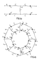
- Figure 4 shows a first example thereof;
- Figure 4a shows a basic section for the coil,
- Figure 4b shows a circuit diagram for the coil, and
- Figure 4c is a perspective view of the coil.
- the coil shown includes eight bar conductors 32 which are accomodated between two ring conductors 30 and 32.
- Each of the bars has a self-inductance L numbered from L1 to L8.
- the looping-through condition found imposes a reactive function on the ring conductor elemements between each pair of bar conductors.
- the reactive elements in a first ring conductor 30 are shown as capacitance which are numbered from C1 to C8; for the second ring conductor 32 there are shown capacitances which are numbered from C9 to C16.
- the ring conductors have an inductive impedance which is represented by self-inductances which are numbered from L9 to L16 for the first ring conductor 30 and from L17 to L24 for the second ring conductor 32.
- the values of the capacitances C1 - C16 and the inductances L9 - L24 are substantially equal.
- a resonant frequency of 64 MHz is obtained for an adapted coil geometry.
- a coil design is obtained which is very suitable for high frequencies.
- a major advantage of the coil shown in figure 4 consists in that the bar conductors do not include capacitive elements.
- the capacitances of the ring conductor elements may be constructed as coaxial coupling pieces so that a compact and rugged coil design is obtained.
- the equivalent diagram for the ring conductor consists of a series connection of a capacitance and a self-inductance.
- Using only an inductance for the bar conductors use can also be made of a parallel connection of, for example, two inductances L1 and L2 and a capacitance C as shown in Figure 5.
- the capacitance has more or less the nature of a parasitic capacitance. For the frequency considered the parallel connection must behave reactively again.
- a substantial additional advantage consists in that a higher degree of freedom is also achieved as regards the design of the external geometry of the coil. This is because when, for example bar conductors must be chosen so as to be thicker, thinner, longer or shorter for some reason, the associated impedance values for the ring conductor elements can be found on the basis of the looping-through condition. Similarly, compensation can be made for variations of, for example the parasitic capacitance of the bar conductors, for example, by a variation of the positions thereof with respect to, for example a Faraday cage 29 in the apparatus. Of course, the reverse is also applicable when the ring conductors must be adapted to external conditions. When sufficient information is available as regards the space and the environment of the coil in a magnetic resonance imaging apparatus, an optimum coil design can thus be provided for any desired resonant frequency.
- a further deviation to be compensated for arises, for example when the coil is to be shaped so as to be non-circular in order to obtain a better filling factor, for example as shown in Figure 7.
- the required impedance value for the relevant position can be simply calculated.
- Such a displacement will often have an effect because the position of the bar conductor is changed by the displacement with respect to the Faraday cage or another conductive element.
- bar conductors are displaced which carry only a small current in accordance with the cosinusoidal distribution.
- a bar conductor which does not carry a current and which hence coincides with the zero crossing of the current distribution can in principle also be omitted or partly omitted.
- a given irregularity may be permitted as regards the distribution thereof over the bar connections, without the homogeneity of the field being disturbed.
- This fact can be used, for example in order to deviated from the geometrical symmetry or from the switching-technical geometry in the coil. This may occur, for example in coil embodiments as shown in Figure 7, in the case of omission of one of the bar conductors, and when tuning and matching circuits are inserted.
- the coil can be powered and read by coupling into one of the bar conductors or by (preferably double) coupling into a ring conductor.
- the tuning of the coil is preferably performed near a coupling between a bar and a ring conductor element.
- a coupling between a bar and a ring conductor element Preferably, it is ensured that the voltage occuring across the capacitances in a conventional tuning circuit does not become excessively high.
- a matching circuit for coupling the transmission and the measurement field in an out, respectively, is also provided near such a coupling and has an impedance 0 for the relevant resonant frequency so that the phase relationship will not be disturbed.
- a 45° bar is to be understood to mean any bar which encloses an angle of 45° with respect to two other bars, regardless of the quadrant and regardless also of the fact whether or not any other bars are present therebetween.
- each of the two coupling points is again preferably situated near bar ends.
Abstract
Description
- The invention relates to a magnetic resonance imaging apparatus which includes a substantially cylindrical r.f. coil in which a number of bar conductors which extend axially across a cylinder surface of the cylinder generate a substantially cosinusoidal current distribution across a circular-cylinder circumference.
- An r.f. coil for such a magnetic resonance imaging apparatus is known from U.S. Patent Specification 4,339,718 and is based on the well-known fact that a cosinusoidal current distribution is required across the circumference of the cylindrical coil in order to obtain a homogeneous field distribution in such a coil. This object is achieved in a coil described therein by arranging pairs of two interconnected bar conductors, having different angles of aperture with respect to the common cylinder axis per pair, symmetrically opposite one another. The desired cosinusoidal current distribution is then obtained by means of a sinusoidal geometrical distribution of the bars. These solutions have many drawbacks; for example there are restrictions as regards the feasible geometry, the construction requires coils having a different radius, and residual inhomogeneity occurs due to the fact that the wires are locally situated far from one another, and that any deviation in the positioning thereof has a direct effect on the homogeneity of the field in the coil. Hereinafter, homogeneity of the field in the coil is to be understood to mean not only the desired homogeneity of an r.f. field to be generated in the coil by the coil, but also the equality of locally distributed measurement points in the coil in the detection of magnetic resonance signals to be emitted by an object. The construction of known coils as described in US 4,439,733 and also with reference to Figure 6 of US 4,339,718 requires a substantial space in the radial direction and is liable to cause interference fields.
- It is an object of the invention to provide a magnetic resonance imaging apparatus which includes an r.f. coil in which said drawbacks are at least substantially mitigated. To achieve this, a magnetic resonance imaging apparatus of the kind set forth in accordance with the invention is characterized in that several bar-shaped conductors are activated via ring conductors and are positioned and coupled so that the following looping-through condition is satisfied:

- Because a coil in accordance with the invention need only satisfy the very general condition given above in order to realize a homogeneous field, a high degree of freedom is achieved as regards the design, so that the design can be adapted to supplementary requirements imposed by the equipment. The above condition inter alia allows for a high degree of freedom as regards the distribution of reactive and inductive elements over the ring conductors and the bar conductors. Moreover, the general formule also enables determination of the extent to which the geometry and distribution of the bars and of the coil can be adapted to other geometrical requirements of the apparatus, such as accessibility for a patient to be examined and adaptation of the shape of the coil to objects to be examined.
- In a preferred embodiment, z₁ is formed by a combination of a reactance and an inductance and z₂ is formed, for example exclusively by an inductance. In a practical embodiment a coil is thus obtained which has capacitances and self-inductances in the ring conductor and a self-inductance in the bar conductor. The combination of a self-inductance and a capacitance in the ring conductor need not necessarily be a series connection of these elements. Using an inductance in the bar conductor, the condition will be satisfied for as long as the ring conductor elements behave capacitively for said frequency and use can be made of, for example, a parasitic-like capacitance or coaxial cables for the ring conductor elements. The capacitance of the ring conductor elements may also be formed by a capacitive coupling to the bar conductors or to subsequent ring conductor elements.
- In a further preferred embodiment, the geometry of the coil is adapted to objects to be measured, for example by making it elliptical instead of circular. Thus, for example more space is created for the shoulders of a patient. Preferably, the bars which do not carry a current or only a small current are displaced furthest. Due to the displacement, a change may occur in the relevant (parasitic) capacitances for these bars. This can be compensated for, for example by constructing the bars to be thinner.
- Similarly, it may be desirable that the bars are not equidistantly distributed over the circumference. Based on the general formule, a homogeneous field can again be ensured in the coil by adaptation of the adjacent ring conductor impedance and/or the impedance of the bar. According to the looping-through condition, the effective impedance per complete ring conductor will represent exactly one whole wavelength for the selected frequency like in the previous embodiments.
- When an orthogonal bar distribution is chosen, which means a number of bars which is a multiple of four, the coil can also be constructed as a quadrature coil. For the single symmetrical tuning to be preferably used in those circumstances, a number of bars from the
progression - When the effect of capacitive elements on the coil is known, the geometry of the coil in the apparatus and, for example a Faraday cage enclosing the coil can be optimized. For example, the Faraday cage may be arranged nearer to the coil when the parasitic reactance of the cage on the ring conductors and the bars is taken into account for the impedance to be included in the coil.
- A coil in accordance with the invention can be tuned, for example by varying the axial dimension of the coil. This method of tuning is particularly attractive for a quadrature coil construction, because the symmetry thereof will not be affected by this method. For the connection of coil conductors to an external power supply source use may be made of a low-ohmic real circuit in one of the conductors. A customary 50-ohm power supply source can be transformed to a desired impedance by capacitive division and addition of an adapted self-inductance.
- Some preferred embodiments in accordance with the invention will be described in detail hereinafter with reference to the drawing. Therein:
- Figure 1 shows a magnetic resonance imaging apparatus in accordance with the invention,
- Figure 2 shows a basic section of an r.f. coil,
- Figure 3 shows a relevant circuit diagram,
- Figure 4 shows a preferred embodiment of a coil in accordance with the invention,
- Figures 5 and 6 show basic sections for further preferred embodiments, and
- Figure 7 shows preferred embodiments of coils adapted to object geometries.
- A magnetic resonance imaging apparatus as shown in Figure 1 includes a
magnet system 2 for generating a steady magnetic field H, a magnet system 4 for generating magnetic gradient fields, andpower supply sources 6 and 8 for themagnet system 2 and the magnet system 4, respectively. An r.f.magnet coil 10 serves to generate an r.f. magnetic alternating field; to this end, it is connected to an r.f.source 12. For the detection of spin resonance signals generated by the r.f. field in an object to be examined, use can also be made of the r.f.coil 10, for which purpose this coil is connected to asignal amplifier 14. Thesignal amplifier 14 is connected to a phase-sensitive rectifier 16 which is connected to acentral control device 18. Thecentral control device 18 also controls amodulator 20 for the r.f.source 12, the power supply source 6, thepower supply source 8 for the gradient coils, and amonitor 22 for display. An r.f.oscillator 24 controls themodulator 20 as well as the phase-sensitive rectifier 16 which processes the measurement signals. For possible cooling of themagnet coils 2 for the main field there is provided acooling device 26 which includescooling ducts 27. Such a cooling device may be constructed for water cooling in the case of resistance coils or, for example for liquid helium cooling for superconducting magnet coils in the present case which involves a high field intensity. Thetransmitter coil 10 arranged within themagnet systems 2 and 4 encloses ameasurement space 28 which is large enough to accomodate patients to be examined in a medical diagnostic apparatus. In themeasurement space 28, therefore, there can be generated a steady magnetic field H, gradient fields for selecting object slices, and a spatially homogeneous r.f. alternating filed. The r.f.coil 10 is capable of combining the functions of transmitter coil and measurement coil. The two functions can alternatively be performed by separate coils; for example, the measurement coils are then formed by surface coils. Hereinafter, thecoil 10 will mostly be referred to as the transmitter coil. In accordance with the theorem of reciprocity, the same considerations hold good when the coil is used as measurement coil. Around thecoil 10 there is provided aFaraday cage 29 which shields the coil from r.f. fields. - Figure 2 shows a circuit diagram of a basic section of an r.f. coil for such a magnetic resonance imaging apparatus. The diagram shows four impedances z₁ which represent mutually equal impedances of the ring conductors which interconnect the bars, an impedance z₂ of a bar conductor, and an impedance z₀ as a terminatiion impedance. None of these impedances is defined as yet. It has been found that for such a basic section generally applicable phase and amplitude conditions can be derived for the power supply of such a section. The phase-difference between e₁ and e₃ in the diagram is denoted by . When basic sections are looped through in order to form a complete coil which includes n bar conductors as diagrammatically shown in Figure 3, there will be a subsidiary condition that e₁ and e₃ must be the same as regards amplitude and that a phase shift = 2 /n must occur between successive conductors. Subject to this condition, a generally applicable condition can be derived in the form of a formule which represents the ratio of the impedances z₁ and z₂ and which, ignoring a correction factor for deviations in, for example the circle geometry or the distance between the bars, contains only the
phase angle 2 /n as a variable. For the sake of brevity, ignoring the correction term, the looping-through condition stated in the preamble can be represented by z₂ = -K z₁, where z₁ and z₂ are said impedances and K is a positive constant value which depends on the number of bar conductors z₁ and z₂ always have the opposite sign; this follows directly from the general formule when it is considered that the quadratic term in the denominator of the lefthand term is always positive. It follows from the opposite sign that when one of the impedances is reactive, that is to say formed, for example by a capacitor, the other impedance must be inductive and hence be formed, for example by a self-inductance or coil. - Subject to the generally applicable looping-through condition, various more or less practical coils can be designed. Figure 4 shows a first example thereof; Figure 4a shows a basic section for the coil, Figure 4b shows a circuit diagram for the coil, and Figure 4c is a perspective view of the coil. The coil shown includes eight
bar conductors 32 which are accomodated between tworing conductors first ring conductor 30 are shown as capacitance which are numbered from C1 to C8; for thesecond ring conductor 32 there are shown capacitances which are numbered from C9 to C16. Furthermore, the ring conductors have an inductive impedance which is represented by self-inductances which are numbered from L9 to L16 for thefirst ring conductor 30 and from L17 to L24 for thesecond ring conductor 32. The values of the capacitances C1 - C16 and the inductances L9 - L24, however, are substantially equal. Using a value of 0.1 µH for the coils of the ring conductors, a value of 0.5 µH for the coils of the bars, and a value of 17.5 pF for the capacitances of the ring conductors, a resonant frequency of 64 MHz is obtained for an adapted coil geometry. Thus, a coil design is obtained which is very suitable for high frequencies. - Another embodiment from the range of coils which can be designed subject to the general looping-through condition is described in EP 141383. The capacitances considered necessary in the bar conductors thereof have been avoided in the above design as they are not very practical elements. An embodiment which is also less practical is obtained when a pure reactance, hence a capacitance, is chosen for the impedance of the bar conductors and a pure inductance, so a coil, is chosen for the ring conductors. Although on the basis of the loopin-through condition a coil which oscillates at a desired frequency can be designed using this geometry, this solution is less practical because, as has already been stated, the bar conductors should include at least also, but preferably only, an inductive element.
- A major advantage of the coil shown in figure 4 consists in that the bar conductors do not include capacitive elements. The capacitances of the ring conductor elements may be constructed as coaxial coupling pieces so that a compact and rugged coil design is obtained. In the example chosen, the equivalent diagram for the ring conductor consists of a series connection of a capacitance and a self-inductance. Using only an inductance for the bar conductors, use can also be made of a parallel connection of, for example, two inductances L1 and L2 and a capacitance C as shown in Figure 5. The capacitance has more or less the nature of a parasitic capacitance. For the frequency considered the parallel connection must behave reactively again. The capacitance having the nature of a parasitic capacitance, the entire parallel connection has the nature of a coaxial cable. when this correspondence is implemented, an equivalent diagram will be obtained as shown in Figure 7, in which a coaxial cable is used for z₁ and an inductance for z₂. When on the basis of this circuit a coil is composed which again comprises eight bars (which is, of course a comparatively arbitrary choice), on the basis of the looping-through condition and for a resonant frequency of 64 MHz, there will be found a capacitance of 10 pF for the cable portion, a self-inductance of 0.5 µH for this portion, and a self-inductance of 0.5 µH for the impedance Z₂. Thus, a coil design is obtained which includes pieces of coaxial cable whose length merely needs adaptation, and bar conductors whose geometry has been adapted. A coil thus designed is extremely practical for very high frequencies in the order of 100 MHz.
- The forgoing examples clearly illustrate the advantage of the general nature of the looping-through condition.
- A substantial additional advantage consists in that a higher degree of freedom is also achieved as regards the design of the external geometry of the coil. This is because when, for example bar conductors must be chosen so as to be thicker, thinner, longer or shorter for some reason, the associated impedance values for the ring conductor elements can be found on the basis of the looping-through condition. Similarly, compensation can be made for variations of, for example the parasitic capacitance of the bar conductors, for example, by a variation of the positions thereof with respect to, for example a
Faraday cage 29 in the apparatus. Of course, the reverse is also applicable when the ring conductors must be adapted to external conditions. When sufficient information is available as regards the space and the environment of the coil in a magnetic resonance imaging apparatus, an optimum coil design can thus be provided for any desired resonant frequency. - A further deviation to be compensated for arises, for example when the coil is to be shaped so as to be non-circular in order to obtain a better filling factor, for example as shown in Figure 7. By determining the number of distinct bar conductors which have been radially displaced, the required impedance value for the relevant position can be simply calculated. Such a displacement will often have an effect because the position of the bar conductor is changed by the displacement with respect to the Faraday cage or another conductive element. Preferably, bar conductors are displaced which carry only a small current in accordance with the cosinusoidal distribution. A bar conductor which does not carry a current and which hence coincides with the zero crossing of the current distribution can in principle also be omitted or partly omitted.
- Corrections can also be made should the uniform distribution of the bar conductors over the surface of the cylinder be disturbed. No inhomogeneities will be introduced into the measurement filed as long as the current distribution across the surface of the (in this case ) equivalent circular-cylinder surface is cosinusoidal, the ring conductors correspond to a whole wavelength, and the impedance values satisfy the looping-through condition.
- For as long as the ring conductors represent a phase shift equivalent to an entire wavelength, a given irregularity may be permitted as regards the distribution thereof over the bar connections, without the homogeneity of the field being disturbed. This fact can be used, for example in order to deviated from the geometrical symmetry or from the switching-technical geometry in the coil. This may occur, for example in coil embodiments as shown in Figure 7, in the case of omission of one of the bar conductors, and when tuning and matching circuits are inserted.
- The coil can be powered and read by coupling into one of the bar conductors or by (preferably double) coupling into a ring conductor.
- The tuning of the coil, the adjustment of the resonant frequency where, for example a range of plus and minus 0.5 MHz for an 100 MHz coil is desirable, is preferably performed near a coupling between a bar and a ring conductor element. Preferably, it is ensured that the voltage occuring across the capacitances in a conventional tuning circuit does not become excessively high. A matching circuit for coupling the transmission and the measurement field in an out, respectively, is also provided near such a coupling and has an impedance 0 for the relevant resonant frequency so that the phase relationship will not be disturbed. When a coil in accordance with the invention is used as a quadrature coil, double tuning would be necessary. However, this can be avoided by providing coils which include such a number of bars that a bar conductor is present every 90° as well as every 45°, with a single tuning circuit in a 45° bar which then serves for the couplings situated at 90° at both sides thereof. Herein, a 45° bar is to be understood to mean any bar which encloses an angle of 45° with respect to two other bars, regardless of the quadrant and regardless also of the fact whether or not any other bars are present therebetween. For the matching of such coils each of the two coupling points is again preferably situated near bar ends. When the bar is suitably interrupted at that area and the interruption is bridged by an adapted matching circuit, any disturbance of the tuning can be prevented and suitable, quasi-earth points can be created for the equipment to be connected.
Claims (12)

Applications Claiming Priority (2)
| Application Number | Priority Date | Filing Date | Title |
|---|---|---|---|
| NL8502273 | 1985-08-19 | ||
| NL8502273A NL8502273A (en) | 1985-08-19 | 1985-08-19 | MAGNETIC RESONANCE DEVICE WITH BIRD CAGE R.F. RINSE. |
Publications (2)
| Publication Number | Publication Date |
|---|---|
| EP0213665A1 true EP0213665A1 (en) | 1987-03-11 |
| EP0213665B1 EP0213665B1 (en) | 1991-01-30 |
Family
ID=19846432
Family Applications (1)
| Application Number | Title | Priority Date | Filing Date |
|---|---|---|---|
| EP86201360A Expired - Lifetime EP0213665B1 (en) | 1985-08-19 | 1986-08-01 | Magnetic resonance imaging apparatus including a bird-cage r.f. coil |
Country Status (11)
| Country | Link |
|---|---|
| US (1) | US4737718A (en) |
| EP (1) | EP0213665B1 (en) |
| JP (1) | JPH0775601B2 (en) |
| KR (1) | KR870002447A (en) |
| CN (1) | CN86105283A (en) |
| BR (1) | BR8603929A (en) |
| CA (1) | CA1254618A (en) |
| DE (1) | DE3677292D1 (en) |
| FI (1) | FI863321A (en) |
| IL (1) | IL79759A0 (en) |
| NL (1) | NL8502273A (en) |
Cited By (3)
| Publication number | Priority date | Publication date | Assignee | Title |
|---|---|---|---|---|
| GB2208937A (en) * | 1987-08-21 | 1989-04-19 | Fuji Electric Co Ltd | Rf coil for nmr imaging |
| US4952878A (en) * | 1988-10-24 | 1990-08-28 | U.S. Philips Corporation | Magnetic resonance apparatus having an improved RF coil |
| WO2003036318A1 (en) * | 2001-10-24 | 2003-05-01 | Koninklijke Philips Electronics N.V. | Radio-frequency coil with two parallel end conductors |
Families Citing this family (34)
| Publication number | Priority date | Publication date | Assignee | Title |
|---|---|---|---|---|
| US4833409A (en) * | 1987-12-21 | 1989-05-23 | General Electric Company | Apparatus for dynamically disabling an NMR field coil |
| NL8802609A (en) * | 1988-10-24 | 1990-05-16 | Philips Nv | MAGNETIC RESONANCE DEVICE WITH OPTIMIZED DETECTION FIELD. |
| US5177441A (en) * | 1989-06-16 | 1993-01-05 | Picker International, Inc. | Elliptical cross section gradient oil |
| WO1991002261A1 (en) * | 1989-08-11 | 1991-02-21 | British Technology Group Plc | Resonant cavities for nmr |
| NL8903066A (en) * | 1989-12-14 | 1991-07-01 | Philips Nv | MAGNETIC RESONANCE DEVICE WITH IMAGE ERROR REDUCTION. |
| NL9001298A (en) * | 1990-06-08 | 1992-01-02 | Philips Nv | RF COILING SYSTEM IN MAGNETIC RESONANCE DEVICE. |
| US5194811A (en) * | 1990-08-02 | 1993-03-16 | Fox Chase Cancer Center | Radio frequency volume resonator for nuclear magnetic resonance |
| US5212450A (en) * | 1990-10-25 | 1993-05-18 | Fox Chase Cancer Center | Radio frequency volume resonator for nuclear magnetic resonance |
| US5202635A (en) * | 1991-01-17 | 1993-04-13 | Fox Chase Cancer Center | Radio frequency volume resonator for nuclear magnetic resonance |
| DE69221835T2 (en) * | 1991-12-11 | 1998-03-05 | Philips Electronics Nv | Magnetic resonance device with a bird cage RF coil |
| US5309104A (en) * | 1992-05-22 | 1994-05-03 | General Electric Company | Asymmetric radio frequency coil for magnetic resonance imaging |
| US5387868A (en) * | 1992-09-29 | 1995-02-07 | U.S. Philips Corporation | Magnetic resonance apparatus |
| US5557247A (en) * | 1993-08-06 | 1996-09-17 | Uab Research Foundation | Radio frequency volume coils for imaging and spectroscopy |
| US5886596A (en) * | 1993-08-06 | 1999-03-23 | Uab Research Foundation | Radio frequency volume coils for imaging and spectroscopy |
| US5483163A (en) * | 1993-08-12 | 1996-01-09 | The United States Of America As Represented By The Department Of Health And Human Services | MRI coil using inductively coupled individually tuned elements arranged as free-pivoting components |
| US5744957A (en) * | 1995-08-15 | 1998-04-28 | Uab Research Foundation | Cavity resonator for NMR systems |
| US7598739B2 (en) * | 1999-05-21 | 2009-10-06 | Regents Of The University Of Minnesota | Radio frequency gradient, shim and parallel imaging coil |
| CA2373526A1 (en) * | 1999-05-21 | 2000-11-30 | The General Hospital Corporation | Tem resonator for magnetic resonance imaging |
| EP2034325A1 (en) * | 2000-07-31 | 2009-03-11 | Regents of the University of Minnesota | Open tem resonators for mri |
| EP1514140A4 (en) * | 2002-05-17 | 2006-01-25 | Mr Instr Inc | A cavity resonator for mr systems |
| CN100526906C (en) * | 2002-11-27 | 2009-08-12 | 皇家飞利浦电子股份有限公司 | Degenerate birdcage coil and transmit/receive apparatus and method for same |
| WO2005111645A2 (en) * | 2004-05-07 | 2005-11-24 | Regents Of The University Of Minnesota | Multi-current elements for magnetic resonance radio frequency coils |
| US7659719B2 (en) * | 2005-11-25 | 2010-02-09 | Mr Instruments, Inc. | Cavity resonator for magnetic resonance systems |
| US8542017B2 (en) * | 2009-12-21 | 2013-09-24 | Nxp B.V. | System and method for measuring the shape of an organ of a patient using a magnetic induction radio sensor integrated in a stretchable strap |
| JP5685476B2 (en) * | 2011-04-11 | 2015-03-18 | 株式会社日立製作所 | Magnetic resonance imaging system |
| CA2853028C (en) | 2011-10-26 | 2016-09-06 | Dainichiseika Color & Chemicals Mfg. Co., Ltd. | Method for eliminating radioactive iodine and hydrophilic resin for eliminating radioactive iodine |
| RU2576020C1 (en) | 2011-12-28 | 2016-02-27 | Дайнитисейка Колор Энд Кемикалс Мфг. Ко., Лтд. | Method for removal of radioactive caesium, hydrophilic resin composition for removal of radioactive caesium, method for removal of radioactive iodine and radioactive caesium and hydrophilic composition for removal of radioactive iodine and radioactive caesium |
| CN104054137B (en) | 2012-01-18 | 2016-09-07 | 大日精化工业株式会社 | The removing method of radiocesium, for removing the removing method of hydrophilic resin oil/fat composition, radioiodine and the radiocesium of radiocesium and for removing the hydrophilic resin oil/fat composition of radioiodine and radiocesium |
| WO2013135251A1 (en) | 2012-03-14 | 2013-09-19 | Max-Planck-Gesellschaft zur Förderung der Wissenschaften e. V. | A method for multi-mode, multi-load, and multi-domain optimization of a multi-channel near-field rf transmitter |
| US9885766B2 (en) | 2012-04-17 | 2018-02-06 | Transarray LLC | Magnetic-resonance transceiver-phased array that compensates for reactive and resistive components of mutual impedance between array elements and circuit and method thereof |
| WO2014129478A1 (en) | 2013-02-19 | 2014-08-28 | 大日精化工業株式会社 | Method for removing radioactive cesium, hydrophilic resin composition for removal of radioactive cesium, method for removing radioactive iodine and radioactive cesium, and hydrophilic resin composition for removal of radioactive iodine and radioactive cesium |
| US10057642B2 (en) * | 2015-10-06 | 2018-08-21 | Comcast Cable Communications, Llc | Controlling the provision of power to one or more devices |
| US11956503B2 (en) | 2015-10-06 | 2024-04-09 | Comcast Cable Communications, Llc | Controlling a device based on an audio input |
| DE102016007832A1 (en) | 2016-06-27 | 2017-12-28 | Giesecke+Devrient Mobile Security Gmbh | Efficient authentication |
Citations (8)
| Publication number | Priority date | Publication date | Assignee | Title |
|---|---|---|---|---|
| GB2050062A (en) * | 1979-05-25 | 1980-12-31 | Emi Ltd | Coils for electromagnets with uniform fields |
| EP0073375A2 (en) * | 1981-08-24 | 1983-03-09 | Siemens Aktiengesellschaft | High-frequency device in a nuclear spin resonance apparatus |
| US4439733A (en) * | 1980-08-29 | 1984-03-27 | Technicare Corporation | Distributed phase RF coil |
| EP0141383A2 (en) * | 1983-11-04 | 1985-05-15 | General Electric Company | Radio frequency field coil for NMR |
| EP0142760A2 (en) * | 1983-11-14 | 1985-05-29 | General Electric Company | Inductively coupled multi-section radio frequency field coil for NMR |
| DE3347597A1 (en) * | 1983-12-30 | 1985-07-18 | Philips Patentverwaltung Gmbh, 2000 Hamburg | HIGH-FREQUENCY COIL ARRANGEMENT FOR GENERATING AND / OR RECEIVING ALTERNATIVE MAGNETIC FIELDS |
| GB2151792A (en) * | 1983-12-23 | 1985-07-24 | Picker Int Ltd | Coil arrangements |
| EP0177855A2 (en) * | 1984-10-09 | 1986-04-16 | General Electric Company | Radio frequency field coil for nmr |
Family Cites Families (1)
| Publication number | Priority date | Publication date | Assignee | Title |
|---|---|---|---|---|
| US4638253A (en) * | 1984-10-29 | 1987-01-20 | General Electric Company | Mutual inductance NMR RF coil matching device |
-
1985
- 1985-08-19 NL NL8502273A patent/NL8502273A/en not_active Application Discontinuation
-
1986
- 1986-08-01 DE DE8686201360T patent/DE3677292D1/en not_active Expired - Lifetime
- 1986-08-01 EP EP86201360A patent/EP0213665B1/en not_active Expired - Lifetime
- 1986-08-01 US US06/891,793 patent/US4737718A/en not_active Expired - Lifetime
- 1986-08-15 FI FI863321A patent/FI863321A/en not_active IP Right Cessation
- 1986-08-15 CA CA000516019A patent/CA1254618A/en not_active Expired
- 1986-08-16 CN CN198686105283A patent/CN86105283A/en active Pending
- 1986-08-18 IL IL79759A patent/IL79759A0/en not_active IP Right Cessation
- 1986-08-18 KR KR1019860006782A patent/KR870002447A/en not_active Application Discontinuation
- 1986-08-18 BR BR8603929A patent/BR8603929A/en unknown
- 1986-08-19 JP JP61192234A patent/JPH0775601B2/en not_active Expired - Fee Related
Patent Citations (8)
| Publication number | Priority date | Publication date | Assignee | Title |
|---|---|---|---|---|
| GB2050062A (en) * | 1979-05-25 | 1980-12-31 | Emi Ltd | Coils for electromagnets with uniform fields |
| US4439733A (en) * | 1980-08-29 | 1984-03-27 | Technicare Corporation | Distributed phase RF coil |
| EP0073375A2 (en) * | 1981-08-24 | 1983-03-09 | Siemens Aktiengesellschaft | High-frequency device in a nuclear spin resonance apparatus |
| EP0141383A2 (en) * | 1983-11-04 | 1985-05-15 | General Electric Company | Radio frequency field coil for NMR |
| EP0142760A2 (en) * | 1983-11-14 | 1985-05-29 | General Electric Company | Inductively coupled multi-section radio frequency field coil for NMR |
| GB2151792A (en) * | 1983-12-23 | 1985-07-24 | Picker Int Ltd | Coil arrangements |
| DE3347597A1 (en) * | 1983-12-30 | 1985-07-18 | Philips Patentverwaltung Gmbh, 2000 Hamburg | HIGH-FREQUENCY COIL ARRANGEMENT FOR GENERATING AND / OR RECEIVING ALTERNATIVE MAGNETIC FIELDS |
| EP0177855A2 (en) * | 1984-10-09 | 1986-04-16 | General Electric Company | Radio frequency field coil for nmr |
Cited By (4)
| Publication number | Priority date | Publication date | Assignee | Title |
|---|---|---|---|---|
| GB2208937A (en) * | 1987-08-21 | 1989-04-19 | Fuji Electric Co Ltd | Rf coil for nmr imaging |
| GB2208937B (en) * | 1987-08-21 | 1992-04-01 | Fuji Electric Co Ltd | High frequency coil |
| US4952878A (en) * | 1988-10-24 | 1990-08-28 | U.S. Philips Corporation | Magnetic resonance apparatus having an improved RF coil |
| WO2003036318A1 (en) * | 2001-10-24 | 2003-05-01 | Koninklijke Philips Electronics N.V. | Radio-frequency coil with two parallel end conductors |
Also Published As
| Publication number | Publication date |
|---|---|
| CN86105283A (en) | 1987-03-18 |
| DE3677292D1 (en) | 1991-03-07 |
| CA1254618A (en) | 1989-05-23 |
| EP0213665B1 (en) | 1991-01-30 |
| BR8603929A (en) | 1987-03-24 |
| KR870002447A (en) | 1987-03-31 |
| JPH0775601B2 (en) | 1995-08-16 |
| US4737718A (en) | 1988-04-12 |
| IL79759A0 (en) | 1986-11-30 |
| NL8502273A (en) | 1987-03-16 |
| FI863321A0 (en) | 1986-08-15 |
| FI863321A (en) | 1987-02-20 |
| JPS6244239A (en) | 1987-02-26 |
Similar Documents
| Publication | Publication Date | Title |
|---|---|---|
| EP0213665B1 (en) | Magnetic resonance imaging apparatus including a bird-cage r.f. coil | |
| US9759788B2 (en) | Magnetic resonance coil, device and system | |
| US6396271B1 (en) | Tunable birdcage transmitter coil | |
| US4952878A (en) | Magnetic resonance apparatus having an improved RF coil | |
| EP0906580B1 (en) | Quadrature elliptical birdcage coil for nmr | |
| EP0180121A2 (en) | Mutual inductance NMR RF coil matching device | |
| JPH0351173B2 (en) | ||
| US5302901A (en) | Magnetic resonance apparatus comprising decoupled receiver coils | |
| US7239139B2 (en) | RF coil system for a magnetic resonance imaging apparatus | |
| EP0173363B1 (en) | Mr-apparatus having a transmission-measuring coil for high frequencies | |
| US5329233A (en) | Cylindrical local coil for nuclear magnetic resonance imaging | |
| EP0829019B1 (en) | Birdcage resonator | |
| US5293126A (en) | Local transverse gradient coil | |
| EP0721592B1 (en) | Rf coil arrangement for a magnetic resonance apparatus | |
| RU2701785C2 (en) | Volumetric radio-frequency coil with improved space and access for use in magnetic resonance imaging system | |
| US6452393B1 (en) | Nuclear magnetic resonance birdcage coil with Cassinian oval former | |
| US5689188A (en) | Magnetic resonance apparatus | |
| US5019778A (en) | Magnetic resonance apparatus with an optimized detection field | |
| KR100530432B1 (en) | Elliptical Orthogonal Bird Cage Coil for NMR |
Legal Events
| Date | Code | Title | Description |
|---|---|---|---|
| PUAI | Public reference made under article 153(3) epc to a published international application that has entered the european phase |
Free format text: ORIGINAL CODE: 0009012 |
|
| AK | Designated contracting states |
Kind code of ref document: A1 Designated state(s): DE FR GB NL |
|
| 17P | Request for examination filed |
Effective date: 19870702 |
|
| 17Q | First examination report despatched |
Effective date: 19890615 |
|
| GRAA | (expected) grant |
Free format text: ORIGINAL CODE: 0009210 |
|
| AK | Designated contracting states |
Kind code of ref document: B1 Designated state(s): DE FR GB NL |
|
| PG25 | Lapsed in a contracting state [announced via postgrant information from national office to epo] |
Ref country code: NL Effective date: 19910130 |
|
| REF | Corresponds to: |
Ref document number: 3677292 Country of ref document: DE Date of ref document: 19910307 |
|
| ET | Fr: translation filed | ||
| NLV1 | Nl: lapsed or annulled due to failure to fulfill the requirements of art. 29p and 29m of the patents act | ||
| PLBE | No opposition filed within time limit |
Free format text: ORIGINAL CODE: 0009261 |
|
| STAA | Information on the status of an ep patent application or granted ep patent |
Free format text: STATUS: NO OPPOSITION FILED WITHIN TIME LIMIT |
|
| 26N | No opposition filed | ||
| REG | Reference to a national code |
Ref country code: FR Ref legal event code: CD |
|
| REG | Reference to a national code |
Ref country code: FR Ref legal event code: CD |
|
| REG | Reference to a national code |
Ref country code: GB Ref legal event code: IF02 |
|
| REG | Reference to a national code |
Ref country code: FR Ref legal event code: D6 |
|
| REG | Reference to a national code |
Ref country code: GB Ref legal event code: 746 Effective date: 20021231 |
|
| PGFP | Annual fee paid to national office [announced via postgrant information from national office to epo] |
Ref country code: DE Payment date: 20041015 Year of fee payment: 19 |
|
| PGFP | Annual fee paid to national office [announced via postgrant information from national office to epo] |
Ref country code: FR Payment date: 20050812 Year of fee payment: 20 |
|
| PGFP | Annual fee paid to national office [announced via postgrant information from national office to epo] |
Ref country code: GB Payment date: 20050830 Year of fee payment: 20 |
|
| PG25 | Lapsed in a contracting state [announced via postgrant information from national office to epo] |
Ref country code: DE Free format text: LAPSE BECAUSE OF NON-PAYMENT OF DUE FEES Effective date: 20060301 |
|
| PG25 | Lapsed in a contracting state [announced via postgrant information from national office to epo] |
Ref country code: GB Free format text: LAPSE BECAUSE OF EXPIRATION OF PROTECTION Effective date: 20060731 |
|
| REG | Reference to a national code |
Ref country code: GB Ref legal event code: PE20 |