EP0217023A2 - Pipelined instruction execution with fast branch instructions - Google Patents
Pipelined instruction execution with fast branch instructions Download PDFInfo
- Publication number
- EP0217023A2 EP0217023A2 EP86109879A EP86109879A EP0217023A2 EP 0217023 A2 EP0217023 A2 EP 0217023A2 EP 86109879 A EP86109879 A EP 86109879A EP 86109879 A EP86109879 A EP 86109879A EP 0217023 A2 EP0217023 A2 EP 0217023A2
- Authority
- EP
- European Patent Office
- Prior art keywords
- microinstruction
- execution
- address
- store
- instruction
- Prior art date
- Legal status (The legal status is an assumption and is not a legal conclusion. Google has not performed a legal analysis and makes no representation as to the accuracy of the status listed.)
- Ceased
Links
Images


Classifications
-
- G—PHYSICS
- G06—COMPUTING; CALCULATING OR COUNTING
- G06F—ELECTRIC DIGITAL DATA PROCESSING
- G06F9/00—Arrangements for program control, e.g. control units
- G06F9/06—Arrangements for program control, e.g. control units using stored programs, i.e. using an internal store of processing equipment to receive or retain programs
- G06F9/22—Microcontrol or microprogram arrangements
- G06F9/28—Enhancement of operational speed, e.g. by using several microcontrol devices operating in parallel
-
- G—PHYSICS
- G06—COMPUTING; CALCULATING OR COUNTING
- G06F—ELECTRIC DIGITAL DATA PROCESSING
- G06F9/00—Arrangements for program control, e.g. control units
- G06F9/06—Arrangements for program control, e.g. control units using stored programs, i.e. using an internal store of processing equipment to receive or retain programs
- G06F9/22—Microcontrol or microprogram arrangements
- G06F9/26—Address formation of the next micro-instruction ; Microprogram storage or retrieval arrangements
- G06F9/262—Arrangements for next microinstruction selection
- G06F9/264—Microinstruction selection based on results of processing
- G06F9/265—Microinstruction selection based on results of processing by address selection on input of storage
Definitions
- the present invention relates to a system and a method for pipelined instruction execution in accordance with the preample of claims 1 and 6.
- a macroinstruction stored in a main memory comprises a plurality of microinstructions.
- each of the microinstructions are executed in sequence. Execution of the macroinstruction is complete when the last of the plurality of microinstructions is executed.
- the macroinstruction is retrieved and decoded into a starting microinstruction address in an instruction decode unit.
- the plurality of microinstructions are usually stored in a Read Only Memory (ROM), connected to the instruction decode unit, in the form of microcode.
- ROM Read Only Memory
- the retrieval of the macroinstruction from main memory necessarily requires the retrieval of the microinstructions from the ROM in response thereto, the microinstructions being executed, in sequence, by an Arithmetic Logic Unit (ALU).
- ALU Arithmetic Logic Unit
- circuits are embodied on integrated circuit chips.
- circuits are embodied on integrated circuit chips.
- These circuits require implementation-space (otherwise referred to as "real estate") on the chips, but the available space on these chips is limited. Therefore, as the number of circuits, required to be embodied on the integrated circuit chips, increases, the available space, or, "real estate", on the chips becomes increasingly more scarce.
- the ROM Due to the need for more space on the integrated circuit chips, it is necessary, in many cases, to reduce the size of the ROM for storage of the microinstructions.
- the ROM is subdivided into two parts: a microstore and a nanostore.
- ROM In a deeply pipelined processor, if the ROM is used to store the microinstructions, one cycle of delay is encountered when a microbranch instruction is being executed by the ALU, and the ALU branches to the "other method" for a solution to the current decision. However, if the microstore and the nanostore, collectively, store the microinstructions, in lieu of the ROM, two cycles of delay are encountered when the microbranch instruction is being executed by the ALU, and the ALU branches to the "other method" for a solution to the current decision.
- the present invention utilizes a no-op/prefetch apparatus in a microstore-nanostore-ALU pipeline for forcing a no-op instruction in the instruction stream being executed by the pipeline when a microbranch instruction is being executed by the ALU of the pipeline, the no-op instruction representing the first cycle of delay following execution of the microbranch instruction, and for prefetching two branch options for execution following the first cycle of delay, the branch option to be executed being dependant upon the branch decision made as a result of execution of the microbranch instruction.
- the invention reduces the size of a microinstruction storage means on the chip and avoids performance losses by increasing the number of delay cycles which are encountered when a processor on the chip executes a microbranch instruction.
- a pipelined processor is capable of executing a two-way conditional branch microinstruction with a single cycle of delay in addition to the execution of the microbranch itself, the additional delay cycle being required for changing direction of the pipeline.
- FIG. 1 a macroinstruction execution system is illustrated.
- macroinstructions are stored in a main memory 10.
- a instruction is retrieved therefrom and decoded in an macroinstruction decode unit 15.
- the instruction decode unit 15 accesses a Read Only Memory (ROM) 20, which stores a plurality of microcode.
- the macroinstruction retrieves a set of microinstructions from the ROM 20, the microinstructions being executed, in sequence, in an Arithmetic Logic Unit (ALU) 30.
- ALU Arithmetic Logic Unit
- the macroinstruction execution system of Figure 1 is implemented on an integrated circuit chip.
- many applications in order to provide additional implementation space, or "real estate", on the chip, it is necessary to reduce the size of the components of Figure 1 on the chip.
- the ROM 20 on the chip the ROM is replaced with two other smaller components, the size of these smaller components being designed to increase the available "real estate" on the integrated circuit chip.
- FIG 2 another macroinstruction execution system is illustrated, this system including the two other smaller components which replace the ROM 20 of Figure 1.
- a microstore 20a one smaller component, is connected to a nanostore 20b, the other smaller component. Therefore, the macroinstruction execution system of Figure 2 includes a main memory 10 connected to an instruction decode unit 15, the instruction decode unit 15 being connected to a microstore 20a, the microstore 20a being connected to nanostore 20b, the nanostore 20b being connected to the ALU 30.
- the main memory 10 is addressed.
- main memory 10 develops output signals representing a macroinstruction.
- the macroinstruction is decoded in the instruction decode unit 15 and accesses microstore 20a.
- Microstore 20a contains one or a plurality of microinstruction addresses corresponding to each macroinstruction; these are to be applied to the nanostore 20b in sequential order; that is, it functions as an addressing means for addressing the nanostore 20b.
- the microstore 20a provides a sequence of microinstruction addresses to the nanostore 20b.
- the nanostore 20b In response to the addressing performed by the microstore 20a, the nanostore 20b develops output signals representing the set of microinstructions corresponding to the macroinstruction retrieved from main memory 10. The set of microinstructions are executed by the ALU 30.
- the pipelining is such that ALU 30 is executing the first microinstruction for the said macroinstruction; nanostore 20b is being accessed for the second microinstruction; microstore 20a is being accessed for the address of the third microinstruction and instruction decoder 15 is holding in readiness the macroinstruction which is to be executed subsequent to the said macroinstruction when the set of microinstructions for said macroinstruction have been accessed in full from microstore 20a.
- the instruction being executed by ALU 30 is a set of microinstructions containing a two way conditional branch microinstruction
- execution of the two way conditional branch microinstruction is complete, one of two possible microinstructions will be executed, depending upon the outcome of the execution of the conditional branch microinstruction.
- the conditional branch microinstruction it is decided to execute a first of the two possible microinstructions
- the microinstructions in the pipeline are executed in-sequence.
- the pipeline is undisturbed.
- the microinstructions in the pipeline are executed out-of-sequence.
- the pipeline is disrupted.
- the Figure 1 system produces one cycle of delay due to the presence of ROM 20, whereas the Figure 2 system produces two cycles of delay due to the presence of microstore 20a and nanostore 20b, since a microbranch decision at ALU 30 must be reflected back to microstore 20a.
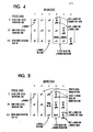
- the pipeline stages associated with the macroinstruction execution system of Figure 1 is illustrated. This system exhibits one cycle of delay; however, available "real estate" is limited on the integrated circuit chip on which the Figure 1 system is disposed.
- the pipeline stages include information relating to the instructions being executed in ROM 20 and ALU 30 during machine cycles 1, 2, 3, and 4.
- microinstruction 10 and microinstruction 9 are associated with ROM 20 and ALU 30, respectively, during machine cycle 1. Assume that microinstruction 10 is a conditional branch microinstruction. During machine cycle 2, ALU 30 is executing conditional branch microinstruction 10. Microinstruction 11 is associated with ROM 20 during this time. During machine cycle 3, microinstruction 11 is being executed by ALU 30. Microinstruction 11 is basically an unused or filler microorder to continue the operation of the pipeline since the results of the microbranch have not yet reached the ALU 30. However, either microinstruction 200 or microinstruction 12 is associated with ROM 20, at this time.
- One of microinstructions 200 or 12 will be executed during machine cycle 4 depending upon the outcome of the execution of microinstruction 10 during machine cycle 2.
- One cycle of delay at ALU 30 is experienced during machine cycle 3 between completion of execution of the conditional branch microinstruction 10 by ALU 30 during machine cycle 2 and the commencement of execution of either microinstruction 12 or microinstruction 200 by ALU 30 during machine cycle 4.
- the pipeline stages of the macroinstruction execution system of Figure 2 is illustrated. This system exhibits two cycles of delay; however, additional "real estate" is available, relative to the system of Figure 1, on the integrated circuit chip on which the Figure 2 system is disposed.
- the pipeline stages include information relating to the microinstructions being executed by the microstore 20a, the nanostore 20b, and the ALU 30 during machine cycles 1 through 6.
- microinstructions 8, 9, and 10 are associated with the ALU 30, nanostore 20b, and microstore 20a, respectively.
- micro instruction 10 is the conditional branch microinstruction.
- microinstructions 9, 10, and 11 are associated with the ALU 30, nanostore 20b, and microstore 20a, respectively.
- microinstructions 10, 11, and 12 are associated with the ALU 30, nanostore 20b, and microstore 20a, respectively. Since microinstruction 10 is the conditional branch microinstruction, ALU 30 will, during machine cycle 3, decide whether the microinstruction to be associated with microstore 20a during machine cycle 4 will be microinstruction 13 or microinstruction 200.
- machine cycles 4 and 5 are delay cycles; that is, these unused cycles must elapse before either microinstruction 13 or microinstruction 200 is executed by the ALU 30 during machine cycle 6. Notice that cycles 4 and 5 represent two cycles of delay.
- microinstructions 13 or 200 are associated with microstore 20a.
- microinstructions 13 or 200 are associated with nanostore 20b.
- the pipeline stages of the macroinstruction execution system of Figure 2, utilizing the no-op/prefetch apparatus according to the present invention, is illustrated.
- This system exhibits only one cycle of delay.
- additional "real estate" is still available, relative to the system of Figure 1, on the integrated circuit chip on which the Figure 2 system is disposed.
- the pipeline stages include information relating to the instructions being executed by the microstore 20a, the nanostore 20b, and the ALU 30 during machine cycles 1 through 5.
- microinstructions 8, 9, and 10 are associated with ALU 30, nanostore 20b, and microstore 20a, respectively.
- microinstruction 10 is the conditional microbranch instruction.
- microinstructions 9, 10, and 11 are associated with ALU 30, nanostore 20b, and microstore 20a, respectively.
- conditional branch microinstruction 10 is being executed by ALU 30.
- microinstruction 11 remains associated with microstore 20a; however, in addition, there is a prefetch of microinstruction 200; it is associated with microstore 20a along with microinstruction 11. Therefore, both microinstruction options, 11 and 200, are associated with microstore 20a.
- microinstruction option 11 or 200 depending upon the resolution of the microbranch, is chosen to be associated with nanostore 20b, and, likewise, either microinstruction option 12 or 201 is associated with microstore 20a.
- ALU 30 will execute either microinstruction 11 or microinstruction 200 depending upon the outcome of the execution of the conditional branch microinstruction 10 by ALU 30 during machine cycle 3. If ALU 30 executes microinstruction 200, microinstruction 201 is associated with nanostore 20b in cycle 5. If ALU 30 executes microinstruction 11, microinstruction 12 is associated with nanostore 20b in cycle 5.
- microstore-nanostore-ALU pipeline which includes the no-op/prefetch apparatus according to the present invention.
- a main memory 10 is connected to the instruction decode unit 15 which is further connected to the microstore 20a by way of a portion of a no-op/prefetch apparatus 50 according to the present invention.
- the microstore 20a is connected to the nanostore 20b by way of another portion of the no-op/prefetch apparatus 50.
- the nanostore 20b is connected to an execution unit (or ALU) 30 via a microcontrol register 40.
- the no-op/prefetch apparatus 50 comprises a microbranch control logic 50a.
- the logic 50a receives a MICROBRANCH TAKEN signal and a MICROBRANCH NOT TAKEN signal from the ALU 30.
- the microbranch control logic 50a is connected to a multiplexer (MUX) 50b via a SELECT line.
- the MUX 50b is connected, at its output, to the nanostore 20b.
- One input of the MUX 50b receives an address of the no-op instruction.
- the other input of MUX 50b is connected to an output of a microstore output register 50c.
- the signal on the SELECT line from logic 50a selects either the one input or the other input of MUX 50b for connection to the MUX 50b output terminal.
- An input of the microstore output register 50c is connected to microstore 20a.
- An output from the microstore output register 50c is connected to microbranch control logic 50a via a MICROBRANCH ORDER line.
- the microbranch control logic 50a is connected to the microstore output register 50c via an INHIBIT LOAD (BRANCH NOT TAKEN) line. Further, the microbranch control logic 50a is connected to a branch address counter 50d via a LOAD line and an INCREMENT line.
- An output from the microstore output register 50c is also connected to the branch address counter 50d via BRANCH TO ADDRESS lines.
- the branch address counter 50d is connected to the second input terminal of a microsequencer 50e and to the second input terminal of another multiplexer (MUX) 50f.
- the first input terminal of the microsequencer 50e is connected to instruction decode unit 15 via a NEW STARTING MICRO-ADDRESS line.
- the output of microsequencer 50e is connected to the first input terminal of MUX 50f.
- the microbranch control logic 50a is connected to MUX 50f via a SELECT line, the signal on the SELECT line of MUX 50f selecting either the output of microsequencer 50e or the output of the branch address counter 50d for connection to the output terminal of MUX 50f.
- the output terminal of MUX 50f is connected to an input of microstore 20a.
- microinstruction 9 is stored in microcontrol register 40.
- Conditional branch microinstruction 10 is stored in the microstore output register 50c.
- Microinstruction 11 is stored in the microsequencer 50e. Recall that, depending upon the outcome of execution of the conditional branch microinstruction 10, either microinstruction 11 or microinstruction 200 will be executed by the ALU during machine cycle 5.
- microinstruction 10 was accessed from microstore 20a and stored in microstore output register 50c at the beginning of machine cycle 2.
- microinstruction 10 informs microbranch control logic 50a that it is a conditional branch microorder via the MICROBRANCH ORDER line connecting register 50c with logic 50a.
- the alternate microprogram address 200 for the microbranch which was defined as part of microinstruction 10
- MUX 50b since MUX 50b is set to select its first input terminal, microinstruction 10, in microstore output register 50c, addresses nanostore 20b thereby selecting a microinstruction associated therewith.
- microinstruction 10 the microbranch, is executed by the ALU 30.
- microinstruction 11 is stored in the microstore output register 50c.
- the microbranch control logic 50a selects, via the SELECT line, the second input terminal of MUX 50b. Therefore, microinstruction 11 does not address the nanostore 20b; rather, an address of the no-op instruction addresses the nanostore 20b via the second input terminal of the MUX 50b.
- Microinstruction 11 remains stored in the microstore output register 50c.
- the branch address counter 50d having been loaded with the address of microinstruction 200 during cycle 2, is selected as the second input terminal of MUX 50f. Therefore, the address of microinstruction 200 is sent to microstore 20a via the second input terminal of MUX 50f.
- the no-op instruction is being executed by the ALU 30. Simultaneously with execution of the no-op instruction, if execution of conditional branch microinstruction 10 indicates that a microbranch should be taken to microinstruction 200, the signal on the INHIBIT LOAD line from the microbranch control logic 50a is low thereby allowing the address of microinstruction 200 to overlay or overwrite the address of microinstruction 11 stored in the microstore output register 50c.
- the nanoaddress associated with microinstruction 200 addresses nanostore 20b, via MUX 50b, retrieving therefrom a microinstruction which is executed by the execu tion unit (ALU) 30 during machine cycle 5.
- address 200 is incremented to 201 in branch address counter 50d and is passed, as the second input, to the microsequencer 50e, thus replacing the microinstruction 12 address.
- the function of microbranch control logic 50a and branch address counter 50d is thus completed and the operation continues normally as microsequencer 50e continues to increment address 201 each machine cycle.
- conditional branch microinstruction 10 indicates that a microbranch should not be taken to microinstruction 200
- the signal on the INHIBIT LOAD line from the microbranch control logic 50a is high thereby preventing the nanoaddress of microinstruction 200 from overlaying or overwriting the address of microinstruction 11 stored in the microstore output register 50c. Therefore, during the execution of the no-op instruction in cycle 4, the nanoaddress associated with microinstruction 11 addresses nanostore 20b, via MUX 50b, retrieving therefrom a microinstruction which is executed by the execution unit (ALU) 30 during machine cycle 5.
- ALU execution unit
Abstract
Description
- The present invention relates to a system and a method for pipelined instruction execution in accordance with the preample of
claims - A macroinstruction stored in a main memory comprises a plurality of microinstructions. When the macroinstruction is executed, each of the microinstructions are executed in sequence. Execution of the macroinstruction is complete when the last of the plurality of microinstructions is executed. When the main memory is addressed, the macroinstruction is retrieved and decoded into a starting microinstruction address in an instruction decode unit. The plurality of microinstructions are usually stored in a Read Only Memory (ROM), connected to the instruction decode unit, in the form of microcode. The retrieval of the macroinstruction from main memory necessarily requires the retrieval of the microinstructions from the ROM in response thereto, the microinstructions being executed, in sequence, by an Arithmetic Logic Unit (ALU).
- As a result of the introduction of large scale integrated circuitry, circuits are embodied on integrated circuit chips. As technology advances, more and more circuits are required to be embodied on these integrated circuit chips. These circuits require implementation-space (otherwise referred to as "real estate") on the chips, but the available space on these chips is limited. Therefore, as the number of circuits, required to be embodied on the integrated circuit chips, increases, the available space, or, "real estate", on the chips becomes increasingly more scarce.
- Due to the need for more space on the integrated circuit chips, it is necessary, in many cases, to reduce the size of the ROM for storage of the microinstructions. In order to reduce the size of the ROM, the ROM is subdivided into two parts: a microstore and a nanostore.
- The subdivision of the ROM into the two parts solves one problem, the need for available "real estate" on a chip. However, it creates another problem, namely, an extra cycle of delay is introduced when the ALU executes a microbranch instruction.
- A microbranch instruction is one which will branch to one of two directions depending upon the result of a decision. For example, in the quotient A/B, if B is not equal to 0, the quotient must be determined by one method, whereas, if B = 0, the quotient must be determined by another method.
- In a deeply pipelined processor, if the ROM is used to store the microinstructions, one cycle of delay is encountered when a microbranch instruction is being executed by the ALU, and the ALU branches to the "other method" for a solution to the current decision. However, if the microstore and the nanostore, collectively, store the microinstructions, in lieu of the ROM, two cycles of delay are encountered when the microbranch instruction is being executed by the ALU, and the ALU branches to the "other method" for a solution to the current decision.
- As a result, in order to provide more available "real estate" on the integrated circuit chips, a performance sacrifice is necessary.
- It is therefore the object of the present invention as claimed to provide more available "real estate" on an integrated circuit chip without detrimentally affecting the performance of the circuits on the chip.
- The present invention utilizes a no-op/prefetch apparatus in a microstore-nanostore-ALU pipeline for forcing a no-op instruction in the instruction stream being executed by the pipeline when a microbranch instruction is being executed by the ALU of the pipeline, the no-op instruction representing the first cycle of delay following execution of the microbranch instruction, and for prefetching two branch options for execution following the first cycle of delay, the branch option to be executed being dependant upon the branch decision made as a result of execution of the microbranch instruction.
- The invention reduces the size of a microinstruction storage means on the chip and avoids performance losses by increasing the number of delay cycles which are encountered when a processor on the chip executes a microbranch instruction.
- A pipelined processor according to the invention is capable of executing a two-way conditional branch microinstruction with a single cycle of delay in addition to the execution of the microbranch itself, the additional delay cycle being required for changing direction of the pipeline.
- A full understanding of the present invention will be obtained from the detailed description of the preferred embodiment presented hereinbelow, and the accompanying drawings, which are given by way of illustration only and are not intended to be limitative of the present invention, and wherein:
- Figure 1 illustrates a block diagram of a typical pipelined macroinstruction execution system;
- Figure 2 illustrates a block diagram of another pipelined macroinstruction execution system, this system possessing a modified microinstruction storage means designed to minimize the available "real estate" on an integrated circuit chip;
- Figure 3 illustrates the pipeline stages of the macroinstruction execution system of figure 1;
- Figure 4 illustrates the pipeline stages of the macroinstruction execution system of figure 2 which does not utilize the no-op/prefetch apparatus according to the present invention;
- Figure 5 illustrates the pipeline stages of the macroinstruction execution system of figure 2 which utilizes the no-op/prefetch apparatus according to the present invention; and
- Figure 6 illustrates a microstore-nanostore-ALU pipeline including the no-op/prefetch apparatus according to the present invention.
- Referring to Figure 1, a macroinstruction execution system is illustrated. In Figure 1, macroinstructions are stored in a
main memory 10. When the main memory is addressed, a instruction is retrieved therefrom and decoded in anmacroinstruction decode unit 15. Theinstruction decode unit 15 accesses a Read Only Memory (ROM) 20, which stores a plurality of microcode. The macroinstruction retrieves a set of microinstructions from theROM 20, the microinstructions being executed, in sequence, in an Arithmetic Logic Unit (ALU) 30. - The macroinstruction execution system of Figure 1 is implemented on an integrated circuit chip. In many applications, in order to provide additional implementation space, or "real estate", on the chip, it is necessary to reduce the size of the components of Figure 1 on the chip. In order to reduce the size of the
ROM 20 on the chip, the ROM is replaced with two other smaller components, the size of these smaller components being designed to increase the available "real estate" on the integrated circuit chip. - In Figure 2, another macroinstruction execution system is illustrated, this system including the two other smaller components which replace the
ROM 20 of Figure 1. In Figure 2, amicrostore 20a, one smaller component, is connected to ananostore 20b, the other smaller component. Therefore, the macroinstruction execution system of Figure 2 includes amain memory 10 connected to aninstruction decode unit 15, theinstruction decode unit 15 being connected to amicrostore 20a, themicrostore 20a being connected tonanostore 20b, thenanostore 20b being connected to theALU 30. - The functional operation of the macroinstruction execution system of Figure 2 will be described in the following paragraph.
- The
main memory 10 is addressed. In response,main memory 10 develops output signals representing a macroinstruction. The macroinstruction is decoded in theinstruction decode unit 15 andaccesses microstore 20a.Microstore 20a contains one or a plurality of microinstruction addresses corresponding to each macroinstruction; these are to be applied to thenanostore 20b in sequential order; that is, it functions as an addressing means for addressing thenanostore 20b. In response to an access by the macroinstruction from themain memory 10, themicrostore 20a provides a sequence of microinstruction addresses to thenanostore 20b. In response to the addressing performed by themicrostore 20a, thenanostore 20b develops output signals representing the set of microinstructions corresponding to the macroinstruction retrieved frommain memory 10. The set of microinstructions are executed by the ALU 30. - The macroinstruction execution systems of Figures 1 and 2 are pipelined systems. The concept of pipelining will be described in the following paragraph with reference to Figures 1 and 2.
- In Figure 1, assuming that each macroinstruction requires only one microinstruction for its execution, while the
ALU 30 is executing a microinstruction corresponding to the first macroinstruction, theROM 20 is being accessed for the microinstruction associated with the second macroinstruction. While theROM 20 is being accessed for the second microinstruction, theinstruction unit 15 is decoding the third macroinstruction andmemory 10 is being accessed in preparation for the retrieval of a fourth macroinstruction therefrom. In Figure 2, while theALU 30 is executing a microinstruction corresponding to a first macroinstruction, thenanostore 20b is being accessed by the output of themicrostore 20a, thenanostore 20b preparing to generate output signals indicative of a microinstruction corresponding to a second macroinstruction. While thenanostore 20b is being accessed, themicrostore 20a is being accessed for a microorder indicative of a third macroinstruction. - When there is a set of microinstructions associated with a macroinstruction, as is the normal case, the pipelining is such that
ALU 30 is executing the first microinstruction for the said macroinstruction;nanostore 20b is being accessed for the second microinstruction;microstore 20a is being accessed for the address of the third microinstruction andinstruction decoder 15 is holding in readiness the macroinstruction which is to be executed subsequent to the said macroinstruction when the set of microinstructions for said macroinstruction have been accessed in full frommicrostore 20a. - If the instruction being executed by
ALU 30 is a set of microinstructions containing a two way conditional branch microinstruction, when execution of the two way conditional branch microinstruction is complete, one of two possible microinstructions will be executed, depending upon the outcome of the execution of the conditional branch microinstruction. If, upon execution of the conditional branch microinstruction, it is decided to execute a first of the two possible microinstructions, the microinstructions in the pipeline are executed in-sequence. The pipeline is undisturbed. However, if, upon execution of the conditional branch microinstruction, it is decided to execute a second of the two possible microinstructions, the microinstructions in the pipeline are executed out-of-sequence. The pipeline is disrupted. - If, in a deeply pipelined processor, it is decided to execute the second of the two possible microinstructions and the microinstructions in the pipeline are executed out-of-sequence, in the Figure 1 system, one cycle of delay will be encountered between completion of execution of the conditional branch microinstruction by
ALU 30 and the execution of the second of the two possible microinstructions byALU 30. However, in the Figure 2 system, two cycles of delay will be encountered between completion of execution of the conditional branch microinstruction byALU 30 and the execution of the second of the two possible microinstructions byALU 30. The Figure 1 system produces one cycle of delay due to the presence ofROM 20, whereas the Figure 2 system produces two cycles of delay due to the presence ofmicrostore 20a andnanostore 20b, since a microbranch decision atALU 30 must be reflected back tomicrostore 20a. - Consequently, by utilizing the macroinstruction execution system of Figure 2, more "real estate" is provided on the integrated circuit chip; however, since the number of cycles of delay has increased, the performance of the Figure 2 system, vis-a-vis the Figure 1 system, is detrimentally affected. This phenomenon, relating to the performance degradation of the Figure 2 system vis-a-vis the Figure 1 system, will be more fully described with reference to the following paragraphs in association with Figures 3 through 5 of the drawings.
- Referring to Figure 3, the pipeline stages associated with the macroinstruction execution system of Figure 1 is illustrated. This system exhibits one cycle of delay; however, available "real estate" is limited on the integrated circuit chip on which the Figure 1 system is disposed. In Figure 3, the pipeline stages include information relating to the instructions being executed in
ROM 20 andALU 30 duringmachine cycles - For example,
microinstruction 10 and microinstruction 9 are associated withROM 20 andALU 30, respectively, duringmachine cycle 1. Assume thatmicroinstruction 10 is a conditional branch microinstruction. Duringmachine cycle 2,ALU 30 is executingconditional branch microinstruction 10.Microinstruction 11 is associated withROM 20 during this time. Duringmachine cycle 3,microinstruction 11 is being executed byALU 30.Microinstruction 11 is basically an unused or filler microorder to continue the operation of the pipeline since the results of the microbranch have not yet reached theALU 30. However, eithermicroinstruction 200 ormicroinstruction 12 is associated withROM 20, at this time. One ofmicroinstructions machine cycle 4 depending upon the outcome of the execution ofmicroinstruction 10 duringmachine cycle 2. One cycle of delay atALU 30 is experienced duringmachine cycle 3 between completion of execution of theconditional branch microinstruction 10 byALU 30 duringmachine cycle 2 and the commencement of execution of eithermicroinstruction 12 ormicroinstruction 200 byALU 30 duringmachine cycle 4. - Referring to Figure 4, the pipeline stages of the macroinstruction execution system of Figure 2 is illustrated. This system exhibits two cycles of delay; however, additional "real estate" is available, relative to the system of Figure 1, on the integrated circuit chip on which the Figure 2 system is disposed. In Figure 4, the pipeline stages include information relating to the microinstructions being executed by the
microstore 20a, thenanostore 20b, and theALU 30 duringmachine cycles 1 through 6. Duringmachine cycle 1,microinstructions 8, 9, and 10 are associated with theALU 30,nanostore 20b, andmicrostore 20a, respectively. Assume thatmicro instruction 10 is the conditional branch microinstruction. Duringmachine cycle 2,microinstructions ALU 30,nanostore 20b, andmicrostore 20a, respectively. Duringmachine cycle 3,microinstructions ALU 30,nanostore 20b, andmicrostore 20a, respectively. Sincemicroinstruction 10 is the conditional branch microinstruction,ALU 30 will, duringmachine cycle 3, decide whether the microinstruction to be associated withmicrostore 20a duringmachine cycle 4 will be microinstruction 13 ormicroinstruction 200. AtALU 30,machine cycles microinstruction 13 ormicroinstruction 200 is executed by theALU 30 duringmachine cycle 6. Notice that cycles 4 and 5 represent two cycles of delay. Duringmachine cycle 4,microinstructions microstore 20a. Duringmachine cycle 5,microinstructions nanostore 20b. - Referring to Figure 5, the pipeline stages of the macroinstruction execution system of Figure 2, utilizing the no-op/prefetch apparatus according to the present invention, is illustrated. This system exhibits only one cycle of delay. Furthermore, additional "real estate" is still available, relative to the system of Figure 1, on the integrated circuit chip on which the Figure 2 system is disposed. In Figure 5, the pipeline stages include information relating to the instructions being executed by the
microstore 20a, thenanostore 20b, and theALU 30 duringmachine cycles 1 through 5. Duringmachine cycle 1,microinstructions 8, 9, and 10 are associated withALU 30,nanostore 20b, andmicrostore 20a, respectively. Assumemicroinstruction 10 is the conditional microbranch instruction. Duringmachine cycle 2,microinstructions ALU 30,nanostore 20b, andmicrostore 20a, respectively. Duringmachine cycle 3,conditional branch microinstruction 10 is being executed byALU 30. Instead of allowingmicroinstruction 11 to associate withnanostore 20b duringmachine cycle 3, a no-op instruction is forced into the pipeline associated withnanostore 20b.Microinstruction 11 remains associated withmicrostore 20a; however, in addition, there is a prefetch ofmicroinstruction 200; it is associated withmicrostore 20a along withmicroinstruction 11. Therefore, both microinstruction options, 11 and 200, are associated withmicrostore 20a. Duringmachine cycle 4, theALU 30 is idle, the no-op microinstruction being associated therewith. The microbranch has been resolved and eithermicroinstruction option nanostore 20b, and, likewise, eithermicroinstruction option microstore 20a. Duringmachine cycle 5,ALU 30 will execute eithermicroinstruction 11 ormicroinstruction 200 depending upon the outcome of the execution of theconditional branch microinstruction 10 byALU 30 duringmachine cycle 3. IfALU 30 executesmicroinstruction 200,microinstruction 201 is associated withnanostore 20b incycle 5. IfALU 30 executesmicroinstruction 11,microinstruction 12 is associated withnanostore 20b incycle 5. - Referring to Figure 6, a microstore-nanostore-ALU pipeline is illustrated, which includes the no-op/prefetch apparatus according to the present invention.
- In Figure 6, a
main memory 10 is connected to theinstruction decode unit 15 which is further connected to themicrostore 20a by way of a portion of a no-op/prefetch apparatus 50 according to the present invention. Themicrostore 20a is connected to the nanostore 20b by way of another portion of the no-op/prefetch apparatus 50. The nanostore 20b is connected to an execution unit (or ALU) 30 via amicrocontrol register 40. - The no-op/
prefetch apparatus 50 comprises amicrobranch control logic 50a. Thelogic 50a receives a MICROBRANCH TAKEN signal and a MICROBRANCH NOT TAKEN signal from theALU 30. Themicrobranch control logic 50a is connected to a multiplexer (MUX) 50b via a SELECT line. TheMUX 50b is connected, at its output, to thenanostore 20b. One input of theMUX 50b receives an address of the no-op instruction. The other input ofMUX 50b is connected to an output of amicrostore output register 50c. The signal on the SELECT line fromlogic 50a selects either the one input or the other input ofMUX 50b for connection to theMUX 50b output terminal. - An input of the
microstore output register 50c is connected tomicrostore 20a. An output from themicrostore output register 50c is connected to microbranchcontrol logic 50a via a MICROBRANCH ORDER line. Themicrobranch control logic 50a is connected to themicrostore output register 50c via an INHIBIT LOAD (BRANCH NOT TAKEN) line. Further, themicrobranch control logic 50a is connected to abranch address counter 50d via a LOAD line and an INCREMENT line. An output from themicrostore output register 50c is also connected to thebranch address counter 50d via BRANCH TO ADDRESS lines. Thebranch address counter 50d is connected to the second input terminal of amicrosequencer 50e and to the second input terminal of another multiplexer (MUX) 50f. The first input terminal of themicrosequencer 50e is connected toinstruction decode unit 15 via a NEW STARTING MICRO-ADDRESS line. The output ofmicrosequencer 50e is connected to the first input terminal ofMUX 50f. Themicrobranch control logic 50a is connected to MUX 50f via a SELECT line, the signal on the SELECT line ofMUX 50f selecting either the output ofmicrosequencer 50e or the output of thebranch address counter 50d for connection to the output terminal ofMUX 50f. The output terminal ofMUX 50f is connected to an input ofmicrostore 20a. - A functional description of the operation of the no-op/prefetch apparatus according to the present invention in association with the microstore-nanostore-ALU pipeline will be set forth in the following paragraphs with reference to Figures 5 and 6 of the drawings.
- In Figure 6, during
machine cycle 2, the execution unit (ALU) 30 is executing microinstruction 9 in a set of microinstructions associated with a given macroinstruction. Therefore, microinstruction 9 is stored inmicrocontrol register 40.Conditional branch microinstruction 10 is stored in themicrostore output register 50c.Microinstruction 11 is stored in themicrosequencer 50e. Recall that, depending upon the outcome of execution of theconditional branch microinstruction 10, eithermicroinstruction 11 ormicroinstruction 200 will be executed by the ALU duringmachine cycle 5. Duringmachine cycle 1,microinstruction 10 was accessed frommicrostore 20a and stored inmicrostore output register 50c at the beginning ofmachine cycle 2. Duringmachine cycle 2,microinstruction 10 informsmicrobranch control logic 50a that it is a conditional branch microorder via the MICROBRANCH ORDERline connecting register 50c withlogic 50a. In addition, duringmachine cycle 2, thealternate microprogram address 200 for the microbranch, which was defined as part ofmicroinstruction 10, is transferred fromregister 50c to branchaddress counter 50d in parallel via the BRANCH-TO-ADDRESS lines. Also, duringmachine cycle 2, sinceMUX 50b is set to select its first input terminal,microinstruction 10, inmicrostore output register 50c, addressesnanostore 20b thereby selecting a microinstruction associated therewith. Duringmachine cycle 3,microinstruction 10, the microbranch, is executed by theALU 30. During this machine cycle, when execution ofmicroinstruction 10 commences,microinstruction 11 is stored in themicrostore output register 50c. However, themicrobranch control logic 50a selects, via the SELECT line, the second input terminal ofMUX 50b. Therefore,microinstruction 11 does not address the nanostore 20b; rather, an address of the no-op instruction addresses the nanostore 20b via the second input terminal of theMUX 50b.Microinstruction 11 remains stored in themicrostore output register 50c. At the same point in time, thebranch address counter 50d, having been loaded with the address ofmicroinstruction 200 duringcycle 2, is selected as the second input terminal ofMUX 50f. Therefore, the address ofmicroinstruction 200 is sent tomicrostore 20a via the second input terminal ofMUX 50f. - During
machine cycle 4, the no-op instruction is being executed by theALU 30. Simultaneously with execution of the no-op instruction, if execution ofconditional branch microinstruction 10 indicates that a microbranch should be taken tomicroinstruction 200, the signal on the INHIBIT LOAD line from themicrobranch control logic 50a is low thereby allowing the address ofmicroinstruction 200 to overlay or overwrite the address ofmicroinstruction 11 stored in themicrostore output register 50c. Therefore, during the execution of the no-op instruction, the nanoaddress associated withmicroinstruction 200 addresses nanostore 20b, viaMUX 50b, retrieving therefrom a microinstruction which is executed by the execu tion unit (ALU) 30 duringmachine cycle 5. At the same point in time, duringcycle 4,address 200 is incremented to 201 inbranch address counter 50d and is passed, as the second input, to themicrosequencer 50e, thus replacing themicroinstruction 12 address. The function ofmicrobranch control logic 50a andbranch address counter 50d is thus completed and the operation continues normally asmicrosequencer 50e continues toincrement address 201 each machine cycle. - However, if execution of
conditional branch microinstruction 10 indicates that a microbranch should not be taken tomicroinstruction 200, the signal on the INHIBIT LOAD line from themicrobranch control logic 50a is high thereby preventing the nanoaddress ofmicroinstruction 200 from overlaying or overwriting the address ofmicroinstruction 11 stored in themicrostore output register 50c. Therefore, during the execution of the no-op instruction incycle 4, the nanoaddress associated withmicroinstruction 11 addresses nanostore 20b, viaMUX 50b, retrieving therefrom a microinstruction which is executed by the execution unit (ALU) 30 duringmachine cycle 5. At the same time, duringcycle 4,microinstruction address 12, being held inmicrosequencer 50e, remains unchanged (is not overwritten with address 201) and is applied to themicrostore 20a. Operation continues in normal fashion.
Claims (6)
first store means (20a) for storing sets of sequential addresses;
second store means (20b) connected to said first store means for storing a plurality of microinstructions, each microinstruction corresponding to an address stored in said first store means;
execution means (30) connected to the second store means for executing a set of microinstructions stored in said second store means in a sequential fashion in accordance with the addresses stored in said first store means;
characterized in that there are provided: first means (50) interconnected between the first and second store means for preventing a microinstruction address from said first store means from accessing said second store means for the purpose of searching for a microinstruction stored therein and for accessing said second store means with an address indicative of a no-op microinstruction when said execution means is executing a conditional branch microinstruction.
control means (50a) connected to said execution means (30) for developing a select signal when said execution means is executing said conditional branch microinstruction; and
multiplexer means (50b) having an output connected to said second store means (20b) and responsive to a first signal representing said address indicative of said no-op instruction, to a second signal representing said microinstruction address from said first store means and to said select signal for selecting said first signal in response to said select signal from said control means (50a) thereby permitting said execution means to execute said no-op instruction.
output register means (50c) interconnected between said first store means (20a) and said multiplexer means (50b) and responsive to said inhibit load signal for preventing said first microinstruction address from being loaded therein in response to said inhibit load signal and for allowing said second microinstruction address to be loaded therein in response to the absence of said inhibit load signal thereby allowing said second microinstruction address to subsequently access said second store means.
characterized by the steps of:
forcing a no-op microinstruction address corresponding to said no-op microinstruction to access said second store means (20b) when said execution means is executing a conditional branch microinstruction; and
preventing a first microinstruction address, representing a next sequential microinstruction following said conditional branch microinstruction, from accessing said second store means (20b) during the execution of said no-op instruction by said execution means when a previous result of the execution of said conditional branch microinstruction indicated that a second microinstruction address, representing another non-sequential microinstruction, should access said second store means.
Applications Claiming Priority (2)
| Application Number | Priority Date | Filing Date | Title |
|---|---|---|---|
| US06/784,073 US4701842A (en) | 1985-10-04 | 1985-10-04 | Method and apparatus for avoiding excessive delay in a pipelined processor during the execution of a microbranch instruction |
| US784073 | 1985-10-04 |
Publications (2)
| Publication Number | Publication Date |
|---|---|
| EP0217023A2 true EP0217023A2 (en) | 1987-04-08 |
| EP0217023A3 EP0217023A3 (en) | 1989-07-26 |
Family
ID=25131265
Family Applications (1)
| Application Number | Title | Priority Date | Filing Date |
|---|---|---|---|
| EP86109879A Ceased EP0217023A3 (en) | 1985-10-04 | 1986-07-18 | Pipelined instruction execution with fast branch instructions |
Country Status (3)
| Country | Link |
|---|---|
| US (1) | US4701842A (en) |
| EP (1) | EP0217023A3 (en) |
| JP (1) | JPS6285338A (en) |
Cited By (5)
| Publication number | Priority date | Publication date | Assignee | Title |
|---|---|---|---|---|
| US6574130B2 (en) | 2001-07-25 | 2003-06-03 | Nantero, Inc. | Hybrid circuit having nanotube electromechanical memory |
| US6643165B2 (en) | 2001-07-25 | 2003-11-04 | Nantero, Inc. | Electromechanical memory having cell selection circuitry constructed with nanotube technology |
| US6706402B2 (en) | 2001-07-25 | 2004-03-16 | Nantero, Inc. | Nanotube films and articles |
| US6784028B2 (en) | 2001-12-28 | 2004-08-31 | Nantero, Inc. | Methods of making electromechanical three-trace junction devices |
| US6835591B2 (en) | 2001-07-25 | 2004-12-28 | Nantero, Inc. | Methods of nanotube films and articles |
Families Citing this family (21)
| Publication number | Priority date | Publication date | Assignee | Title |
|---|---|---|---|---|
| US4991080A (en) * | 1986-03-13 | 1991-02-05 | International Business Machines Corporation | Pipeline processing apparatus for executing instructions in three streams, including branch stream pre-execution processor for pre-executing conditional branch instructions |
| US5590293A (en) * | 1988-07-20 | 1996-12-31 | Digital Equipment Corporation | Dynamic microbranching with programmable hold on condition, to programmable dynamic microbranching delay minimization |
| US5019967A (en) * | 1988-07-20 | 1991-05-28 | Digital Equipment Corporation | Pipeline bubble compression in a computer system |
| US5101341A (en) * | 1988-08-25 | 1992-03-31 | Edgcore Technology, Inc. | Pipelined system for reducing instruction access time by accumulating predecoded instruction bits a FIFO |
| US5329621A (en) * | 1989-10-23 | 1994-07-12 | Motorola, Inc. | Microprocessor which optimizes bus utilization based upon bus speed |
| US5471593A (en) * | 1989-12-11 | 1995-11-28 | Branigin; Michael H. | Computer processor with an efficient means of executing many instructions simultaneously |
| US5524222A (en) * | 1992-03-27 | 1996-06-04 | Cyrix Corporation | Microsequencer allowing a sequence of conditional jumps without requiring the insertion of NOP or other instructions |
| JP3499252B2 (en) * | 1993-03-19 | 2004-02-23 | 株式会社ルネサステクノロジ | Compiling device and data processing device |
| US5379442A (en) * | 1993-03-31 | 1995-01-03 | Intel Corporation | Fast primary and feedback path in a programmable logic circuit |
| US5928357A (en) * | 1994-09-15 | 1999-07-27 | Intel Corporation | Circuitry and method for performing branching without pipeline delay |
| US5619408A (en) * | 1995-02-10 | 1997-04-08 | International Business Machines Corporation | Method and system for recoding noneffective instructions within a data processing system |
| US5847929A (en) * | 1996-06-28 | 1998-12-08 | International Business Machines Corporation | Attaching heat sinks directly to flip chips and ceramic chip carriers |
| US7566478B2 (en) | 2001-07-25 | 2009-07-28 | Nantero, Inc. | Methods of making carbon nanotube films, layers, fabrics, ribbons, elements and articles |
| US6924538B2 (en) | 2001-07-25 | 2005-08-02 | Nantero, Inc. | Devices having vertically-disposed nanofabric articles and methods of making the same |
| US7259410B2 (en) | 2001-07-25 | 2007-08-21 | Nantero, Inc. | Devices having horizontally-disposed nanofabric articles and methods of making the same |
| US6911682B2 (en) | 2001-12-28 | 2005-06-28 | Nantero, Inc. | Electromechanical three-trace junction devices |
| US6919592B2 (en) | 2001-07-25 | 2005-07-19 | Nantero, Inc. | Electromechanical memory array using nanotube ribbons and method for making same |
| US7176505B2 (en) | 2001-12-28 | 2007-02-13 | Nantero, Inc. | Electromechanical three-trace junction devices |
| US7335395B2 (en) | 2002-04-23 | 2008-02-26 | Nantero, Inc. | Methods of using pre-formed nanotubes to make carbon nanotube films, layers, fabrics, ribbons, elements and articles |
| US7560136B2 (en) | 2003-01-13 | 2009-07-14 | Nantero, Inc. | Methods of using thin metal layers to make carbon nanotube films, layers, fabrics, ribbons, elements and articles |
| US9043579B2 (en) | 2012-01-10 | 2015-05-26 | International Business Machines Corporation | Prefetch optimizer measuring execution time of instruction sequence cycling through each selectable hardware prefetch depth and cycling through disabling each software prefetch instruction of an instruction sequence of interest |
Citations (2)
| Publication number | Priority date | Publication date | Assignee | Title |
|---|---|---|---|---|
| US3886523A (en) * | 1973-06-05 | 1975-05-27 | Burroughs Corp | Micro program data processor having parallel instruction flow streams for plural levels of sub instruction sets |
| GB2081944A (en) * | 1980-08-12 | 1982-02-24 | Technology Marketing Inc | Microinstruction sequence control |
Family Cites Families (7)
| Publication number | Priority date | Publication date | Assignee | Title |
|---|---|---|---|---|
| US4099229A (en) * | 1977-02-14 | 1978-07-04 | The United States Of America As Represented By The Secretary Of The Navy | Variable architecture digital computer |
| US4128873A (en) * | 1977-09-20 | 1978-12-05 | Burroughs Corporation | Structure for an easily testable single chip calculator/controller |
| US4415969A (en) * | 1980-02-07 | 1983-11-15 | Intel Corporation | Macroinstruction translator unit for use in a microprocessor |
| US4373180A (en) * | 1980-07-09 | 1983-02-08 | Sperry Corporation | Microprogrammed control system capable of pipelining even when executing a conditional branch instruction |
| US4390946A (en) * | 1980-10-20 | 1983-06-28 | Control Data Corporation | Lookahead addressing in a pipeline computer control store with separate memory segments for single and multiple microcode instruction sequences |
| US4507732A (en) * | 1981-10-05 | 1985-03-26 | Burroughs Corporation | I/O subsystem using slow devices |
| JPS60183634A (en) * | 1984-03-02 | 1985-09-19 | Hitachi Ltd | Microprogram control system |
-
1985
- 1985-10-04 US US06/784,073 patent/US4701842A/en not_active Expired - Fee Related
-
1986
- 1986-07-14 JP JP61163943A patent/JPS6285338A/en active Granted
- 1986-07-18 EP EP86109879A patent/EP0217023A3/en not_active Ceased
Patent Citations (2)
| Publication number | Priority date | Publication date | Assignee | Title |
|---|---|---|---|---|
| US3886523A (en) * | 1973-06-05 | 1975-05-27 | Burroughs Corp | Micro program data processor having parallel instruction flow streams for plural levels of sub instruction sets |
| GB2081944A (en) * | 1980-08-12 | 1982-02-24 | Technology Marketing Inc | Microinstruction sequence control |
Non-Patent Citations (1)
| Title |
|---|
| MICROPROCESSING AND MICROPROGRAMMING, vol. 9, no. 3, pages 155-160, March 1982, Amsterdam, NL; H. SCHECHER et al.: "Avoiding gaps in a three-level pipelined micro-control-unit" * |
Cited By (9)
| Publication number | Priority date | Publication date | Assignee | Title |
|---|---|---|---|---|
| US6574130B2 (en) | 2001-07-25 | 2003-06-03 | Nantero, Inc. | Hybrid circuit having nanotube electromechanical memory |
| US6643165B2 (en) | 2001-07-25 | 2003-11-04 | Nantero, Inc. | Electromechanical memory having cell selection circuitry constructed with nanotube technology |
| US6706402B2 (en) | 2001-07-25 | 2004-03-16 | Nantero, Inc. | Nanotube films and articles |
| US6836424B2 (en) | 2001-07-25 | 2004-12-28 | Nantero, Inc. | Hybrid circuit having nanotube electromechanical memory |
| US6835591B2 (en) | 2001-07-25 | 2004-12-28 | Nantero, Inc. | Methods of nanotube films and articles |
| US7745810B2 (en) | 2001-07-25 | 2010-06-29 | Nantero, Inc. | Nanotube films and articles |
| US8101976B2 (en) | 2001-07-25 | 2012-01-24 | Nantero Inc. | Device selection circuitry constructed with nanotube ribbon technology |
| US6784028B2 (en) | 2001-12-28 | 2004-08-31 | Nantero, Inc. | Methods of making electromechanical three-trace junction devices |
| US7915066B2 (en) | 2001-12-28 | 2011-03-29 | Nantero, Inc. | Methods of making electromechanical three-trace junction devices |
Also Published As
| Publication number | Publication date |
|---|---|
| EP0217023A3 (en) | 1989-07-26 |
| US4701842A (en) | 1987-10-20 |
| JPS6285338A (en) | 1987-04-18 |
| JPH0318210B2 (en) | 1991-03-12 |
Similar Documents
| Publication | Publication Date | Title |
|---|---|---|
| EP0217023A2 (en) | Pipelined instruction execution with fast branch instructions | |
| EP0689128B1 (en) | Computer instruction compression | |
| US4594682A (en) | Vector processing | |
| US4734852A (en) | Mechanism for performing data references to storage in parallel with instruction execution on a reduced instruction-set processor | |
| USRE43248E1 (en) | Interoperability with multiple instruction sets | |
| US5819058A (en) | Instruction compression and decompression system and method for a processor | |
| CA1320275C (en) | Pipeline bubble compression in a computer system | |
| US4187539A (en) | Pipelined data processing system with centralized microprogram control | |
| EP0415461B1 (en) | Central processing unit supporting variable length instructions | |
| US5396634A (en) | Method and apparatus for increasing the decoding speed of a microprocessor | |
| US4587632A (en) | Lookahead stack oriented computer | |
| WO1990003001A1 (en) | Pipeline structures and methods | |
| EP0352082B1 (en) | Microinstruction addressing in a pipeline-CPU (operating method, addressing method, memory stack and CPU ) | |
| EP0136183B1 (en) | Control store arrangement for enhanced cpu pipeline performance | |
| US3958221A (en) | Method and apparatus for locating effective operand of an instruction | |
| US5978896A (en) | Method and system for increased instruction dispatch efficiency in a superscalar processor system | |
| US4812971A (en) | Central processing unit for a digital computer | |
| EP0650612B1 (en) | Fast instruction decoding in a pipeline processor | |
| US4893235A (en) | Central processing unit for a digital computer | |
| JPS5822450A (en) | Microprogrammed data processing system | |
| US5928357A (en) | Circuitry and method for performing branching without pipeline delay | |
| US5537627A (en) | Microprogrammable processor capable of accessing unused portions of control store as fast data memory | |
| JPH031231A (en) | Microprogram controller | |
| EP0162928B1 (en) | Microprogram control method | |
| US5864877A (en) | Apparatus and method for fast forwarding of table index (TI) bit for descriptor table selection |
Legal Events
| Date | Code | Title | Description |
|---|---|---|---|
| PUAI | Public reference made under article 153(3) epc to a published international application that has entered the european phase |
Free format text: ORIGINAL CODE: 0009012 |
|
| AK | Designated contracting states |
Kind code of ref document: A2 Designated state(s): DE FR GB |
|
| 17P | Request for examination filed |
Effective date: 19870821 |
|
| PUAL | Search report despatched |
Free format text: ORIGINAL CODE: 0009013 |
|
| AK | Designated contracting states |
Kind code of ref document: A3 Designated state(s): DE FR GB |
|
| 17Q | First examination report despatched |
Effective date: 19911017 |
|
| STAA | Information on the status of an ep patent application or granted ep patent |
Free format text: STATUS: THE APPLICATION HAS BEEN REFUSED |
|
| 18R | Application refused |
Effective date: 19921219 |
|
| RIN1 | Information on inventor provided before grant (corrected) |
Inventor name: OLNOWICH, HOWARD THOMAS |