EP0218259A2 - Method and apparatus for calculating position and orientation by combination of features of partial shapes - Google Patents
Method and apparatus for calculating position and orientation by combination of features of partial shapes Download PDFInfo
- Publication number
- EP0218259A2 EP0218259A2 EP86114039A EP86114039A EP0218259A2 EP 0218259 A2 EP0218259 A2 EP 0218259A2 EP 86114039 A EP86114039 A EP 86114039A EP 86114039 A EP86114039 A EP 86114039A EP 0218259 A2 EP0218259 A2 EP 0218259A2
- Authority
- EP
- European Patent Office
- Prior art keywords
- orientation
- gravity
- calculated
- feature
- image
- Prior art date
- Legal status (The legal status is an assumption and is not a legal conclusion. Google has not performed a legal analysis and makes no representation as to the accuracy of the status listed.)
- Granted
Links
Images


Classifications
-
- G—PHYSICS
- G06—COMPUTING; CALCULATING OR COUNTING
- G06T—IMAGE DATA PROCESSING OR GENERATION, IN GENERAL
- G06T7/00—Image analysis
- G06T7/70—Determining position or orientation of objects or cameras
- G06T7/73—Determining position or orientation of objects or cameras using feature-based methods
-
- G—PHYSICS
- G06—COMPUTING; CALCULATING OR COUNTING
- G06V—IMAGE OR VIDEO RECOGNITION OR UNDERSTANDING
- G06V10/00—Arrangements for image or video recognition or understanding
- G06V10/40—Extraction of image or video features
Definitions
- the present invention relates to a method and an apparatus for image recognition to calculate the position and orientation of an object article and, more particularly, to a method and an apparatus for calculating the position and orientation of a whole object article inclusive of its partial shapes by computing the linear equations, centers of gravity and so forth of such partial shapes.
- the object article to be recognized is a printed circuit board or the like with electronic components mounted thereon and its image is extremely complicated or its external dimensions are large, there exist some disadvantages including that a distinct image of the whole object article cannot be obtained immediately or its shape cannot be obtained simultaneously. Consequently, fast calculation of feature parameters is not attainable with facility to substantially fail in proper recognition of the object article in practical operation.
- Another object of the invention resides in providing a method and an apparatus capable of extracting the position and orientation of a whole object article with simplicity and rapidity even when the object article is dimensionally large or its image is complicated.
- the present invention is so contrived as to calculate the current position and orientation of the object article on the basis of two given points, or one given point and one given linear equation, or two given linear equations in the object article. That is, if the position and orientation of the object article are at random within a certain range, the approximate position of any predetermined partial shapes can also be known before the image processing, so that it is possible to detect the position and orientation of the whole object article from the combination of selected partial shapes to calculate the feature parameters such as the center of gravity, linear equations through image processing.
- Fig. l shows an exemplary constitution of such a system.
- a chassis 2 transported on a belt conveyor l at random is picked up by a TV camera 3, and the entire or partial picture image of the chassis 2 is transmitted to an image processor 4, where the position and orientation of the chassis 2 are calculated from the input image and are fed to an assembly robot 5.
- the robot 5 takes out a part from a part supply magazine 6 and attaches it to the chassis 2 while correcting the position and orientation of the part to reference ones in conformity with the information received from the image processor 4.
- the chassis 2 is placed in two-dimensional arbitrary position and orientation on the belt conveyor l, and for enabling the robot 5 to perform exact attachment of each part to the chassis 2, the reference position and orientation data need to be corrected on the basis of the deviation of the chassis 2 computed from the input picture image.
- the block diagram of Fig. 2 shows a hardware constitution of the image processor 4.
- the input picture image from the TV camera 3 is fed to a video input/output unit 23 and then is binary-coded for segmentation in a video processing unit, which thereby divides the image into black and white regions.
- the subsequent processing program is previously prepared on a floppy disk 27.
- the program thus prepared on the floppy disk 27 is stored in a memory 20 such as a magnetic bubble memory via a floppy disk interface 2l, and also dictionary data is stored in the memory 20.
- processing program and the dictionary data stored in the memory 20 are transferred to a memory on a central processing unit (CPU) in response to an instruction from the robot 5 and an instruction from a console 26 via s serial input/output interface 25, whereby the process is executed as shown in Fig. 8.
- CPU central processing unit
- Fig. 3 shows some exemplary patterns of partial shapes.
- a portion of the substrate mounted on the chassis 2 is detected as an image 8 which includes a connector image 9, a hole image l0, substrate edge images ll, l2 and so forth to be extracted and processed as partial shapes.
- the partial shapes can be extracted out of the windows l3 - l6 preset in a suitable manner. Accordingly, the partial shapes thus extracted are classified into those representing the entire features such as hole image l0 and those representing the partial features such as connector image 9 and substrate edge images ll, l2.
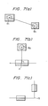
- Fig. 4 (a) and (b) illustrate exemplary partial shapes extracted.
- a hole image l0 representing an entire feature is segmented for polygonal approximation, wherein the coordinates of a sequence of points (marked with circles) are preserved as data.
- a substrate edge image ll representing a partial feature and the frame of a window l5 are segmented for polygonal approximation and, with another window l8 set in the inner area except such frame of the window l5, merely the partial shape to be extracted is approximated to a sequence of segments, wherein the coordinates of a sequence of points (marked with circles) are preserved as data.
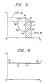
- Figs. 5 and 6 graphically show how a feature parameter is extracted from the segmented contour obtained in Fig. 4 (a) and (b), respectively.
- the center of gravity (centroid) G is calculated.
- the x-coordinate xg and the y-coordinate yg of the center of gravity G are obtained as follows from the primary moments Mx, My and the area S of the whole polygon defined with a unitary trapezoid [TxPl, P2], [TyPl, P2] shown in Fig.
- Fig. 7 (a) through (c) a description will be given on the method of calculating the position and orientation on the basis of the feature parameters obtained in the manner mentioned.
- the feature parameters obtained are centers of gravity and straight lines
- the combinations thereof include (a) center of gravity and center of gravity; (b) center of gravity and straight line; and (c) straight line and straight line.
- the method of calculating the position and orientation will be described with regard to the individual combinations.
- deviations from the reference position and orientation are in the x-direction, y-direction and rotational direction on the x-y plane.
- the position of one partial shape and hence the positional deviations in the x- and y-directions can be calculated from the center of gravity Gl (x1g, y1g) relative to the feature-shaped portion, while the deviation angle ⁇ in the rotational direction is calculated as follows from Gl (x1g, y1g) and G2 (x2g, y1g).
- ⁇ tan ⁇ 1 (y′ - y3g / x′ - x3g) .
- ⁇ tan ⁇ 1 a or tan ⁇ 1 a" .
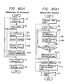
- Fig. 8 is a flow chart of an exemplary position and orientation calculating process executed by the method shown in Fig. 7 (a) through (c).
- the position and orientation of input data are recognized by computing the deviation of the input data in comparison with reference data.
- the entire process is divided into (a) preparation of a dictionary serving as basic data, and (b) a recognition process for computing the deviation by comparison with the dictionary data.
- a picture image based on the camera number and the stage number designated in Sl is inputted from the TV camera 3 [S2].
- the input picture image illustrated in Fig. 3 for example, the coordinates of a right upper point and a left lower point in the square including feature shapes of Fig. 4 (a) and (b) are specified, and a window (e.g. l3 in Fig. 3) is set for defining a processing range and is registered [S3l].
- the contour of the feature shape within the registered window is extracted [S32] and then is classified by the extractable feature parameter [S33].
- the feature parameter such as center of gravity or linear equation designated per classified feature shape is extracted and registered as a value relative to the registered window (l3 in Fig. l3) [S34].
- the steps S3l through S34 are concerned with each of the windows [S3].
- Such step S3 for each window is executed with respect to the entirety of the feature shapes required for position and orientation recognition on the picture image currently inputted.
- the corresponding camera number and stage number are designated [Sl] and, after the picture image is inputted [S2], the intrawindow process [S3] is executed.
- windows including the feature shapes to be combined are designated [S4]
- dictionary data are registered in the memory 20 such as camera number, window size and position, feature parameter to be extracted, value of such parameter, windows to be combined and so forth [S5].
- the feature parameter to be calculated is basically represented by a linear equation which extracts, in the form of a straight line, the center of gravity obtained from the entire feature shape and a partial feature.
- a linear equation which extracts, in the form of a straight line, the center of gravity obtained from the entire feature shape and a partial feature.
- a secondary moment can be calculated to enable judgment of a position and an orientation by a single feature parameter.
- calculating a linear equation there exists a case where two straight lines forming a hook in a special mode are obtained simultaneously. In such a case, the position and orien tation can be calculated by two straight lines included in one partial shape, and the intersection of such two straight lines can be calculated immediately.
- Fig. 9 illustrates four patterns of feature shapes classified by taking into consideration the case where special feature parameters can be obtained, such as center of gravity plus secondary moment, and two straight lines plus intersection.
- feature shapes are assorted into: (l) a pattern where merely a center of gravity can be calculated from the entire feature shape; (2) a pattern where a center of gravity and a secondary moment can be calculated from the calculated from the entire feature shape; (3) a pattern where one straight line can be calculated; and (4) a pattern where two nonparallel straight lines or such two lines and an intersection thereof can be calculated.
- high-precision judgment is achievable if the two straight lines are sufficiently long, but stability is not ensured when the lines are short, so that a sole judgment is not approvable.
- the image processor 4 is actuated by the robot 5 to execute operating instructions [S6].
- the designated camera number and stage number are image-inputted into the image processor 4 in response to such instructions [S7].
- the window registered at the time of preparing the dictionary is set with regard to the window including feature shapes to be used, and subsequently extraction of the intrawindow feature shapes [S8l] and extraction of the feature parameters [S82] are executed in the same manner as at the time of preparing the dictionary.
- the extracted data is checked whether it is the object pattern or not on the basis of the area value and so forth, and the extracted data is registered as recognition data in case the result of such check is OK [S84]. If the result is not OK, the process advances to the step for the next window.
- the images thereof are inputted so that the feature parameters are extracted with respect to all the feature shapes [S8].
- the windows are combined [S9] in accordance with the dictionary data, the deviation or difference from the dictionary data is computed by the method mentioned with reference to Fig. 7 (a) - (c) [Sl0].
- the deviation obtained in the preceding step is converted into a robotic coordinate system and the resultant value is transmitted to the robot 5, or the deviation is checked to ascertain whether it is within the allowable range or not and then the result is transmitted to the robot 5 [Sll].
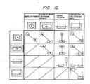
- Fig. l0 shows how a position and an orientation are calculated by a combination of the feature shapes illustrated in Fig. 8. Any combination is possible among all of the four patterns. For example, in a combination where two intersections of two straight lines are obtained, the position and orientation can be calculated in the same manner as in a combination where two centers of gravity are obtained. In other cases also, the position and orientation of the whole object article can be calculated on the basis of two partial feature shapes.
- the present invention is so contrived as to perform proper recognition of the position and orientation of the whole object article from one or more partial shapes thereof. Accordingly, if the object article is dimensionally large or its image is complicated, remarkable effect is still achievable in properly recognizing the position and orientation of the whole object article.
Abstract
Description
- The present invention relates to a method and an apparatus for image recognition to calculate the position and orientation of an object article and, more particularly, to a method and an apparatus for calculating the position and orientation of a whole object article inclusive of its partial shapes by computing the linear equations, centers of gravity and so forth of such partial shapes.
- In the part recognition technology developed heretofore, there is known an exemplary pattern recognition apparatus disclosed in Japanese Patent Laid-open No. 59 (l984)-l54574 (Patent Application No. 58 (l983)-275l8, U.S. Patent Serial No. 582,555). According to this prior art, the pattern of an object article is recognized by first detecting the entire contour thereof and, after calculating its feature parameters such as center of gravity, principal axis and so forth, finding the degree of coincidence between the pattern of the object article and a selected dictionary pattern in a state where the two patterns are so set that the respective principal axes coincide with each other. However, in case the object article to be recognized is a printed circuit board or the like with electronic components mounted thereon and its image is extremely complicated or its external dimensions are large, there exist some disadvantages including that a distinct image of the whole object article cannot be obtained immediately or its shape cannot be obtained simultaneously. Consequently, fast calculation of feature parameters is not attainable with facility to substantially fail in proper recognition of the object article in practical operation.
- Meanwhile, in Japanese Patent Laid-open No. 58 (l983)-62503, there is disclosed an invention which executes controlled positioning of a member on the basis of its area in a window set in a part of the image. However, since the positioning in the above example is performed merely using the area parameter, a precise position is not achievable.
- Generally it has been customary in the prior art to place an object article under positive control so that its predetermined reference position and orientation are retained. When the position and orientation are properly recognized, the correlation between them and the reference ones is defined uniquely so that the object article can be controlled properly by correcting the reference position and orientation in accordance with such correlation. That is, proper control of the object article is sufficiently attainable by proper recognition of the current position and orientation.
- It is an object of the present invention to provide a method and an apparatus adapted for calculating the position and orientation of an object article properly not from its entire shape but from its partial feature shapes.
- And another object of the invention resides in providing a method and an apparatus capable of extracting the position and orientation of a whole object article with simplicity and rapidity even when the object article is dimensionally large or its image is complicated.
- In order to accomplish the objects mentioned above, the present invention is so contrived as to calculate the current position and orientation of the object article on the basis of two given points, or one given point and one given linear equation, or two given linear equations in the object article. That is, if the position and orientation of the object article are at random within a certain range, the approximate position of any predetermined partial shapes can also be known before the image processing, so that it is possible to detect the position and orientation of the whole object article from the combination of selected partial shapes to calculate the feature parameters such as the center of gravity, linear equations through image processing.
-
- Fig. l shows a robotized automatic assembly system to which the present invention is applied;
- Fig. 2 is a block diagram showing a hardware constitution of an image processor in the system of Fig. l;
- Fig. 3 illustrates how windows are set for partial shapes according to the present invention;
- Fig. 4 illustrates exemplary polygonal approximations of partial shapes extracted through the windows, in which (a) shows a hole image and (b) a substrate edge image represented by a polygonal approximation, respectively;
- Figs. 5 and 6 graphically show how a feature parameter is extracted from a segmented contour obtained in Fig. 4 (a) and (b), respectively;
- Fig. 7 (a) through (c) schematically illustrate the method of this invention for calculating a position and a orientation;
- Fig. 8 is a flow chart of an exemplary position and orientation calculating process according to the present invention, in which (a) represents preparation of a dictionary, and (b) a recognition process;
- Fig. 9 illustrates four fundamental patterns of feature shapes in this invention; and
- Fig. l0 illustrates combinations of feature of partial shapes to explain the method of this invention.
- First an explanation will be given on a robotized automatic assembly system to which the present invention is applicable. Fig. l shows an exemplary constitution of such a system. As illustrated, a
chassis 2 transported on a belt conveyor l at random is picked up by aTV camera 3, and the entire or partial picture image of thechassis 2 is transmitted to animage processor 4, where the position and orientation of thechassis 2 are calculated from the input image and are fed to anassembly robot 5. Then therobot 5 takes out a part from apart supply magazine 6 and attaches it to thechassis 2 while correcting the position and orientation of the part to reference ones in conformity with the information received from theimage processor 4. Generally thechassis 2 is placed in two-dimensional arbitrary position and orientation on the belt conveyor l, and for enabling therobot 5 to perform exact attachment of each part to thechassis 2, the reference position and orientation data need to be corrected on the basis of the deviation of thechassis 2 computed from the input picture image. - The block diagram of Fig. 2 shows a hardware constitution of the
image processor 4. The input picture image from theTV camera 3 is fed to a video input/output unit 23 and then is binary-coded for segmentation in a video processing unit, which thereby divides the image into black and white regions. The subsequent processing program is previously prepared on afloppy disk 27. The program thus prepared on thefloppy disk 27 is stored in amemory 20 such as a magnetic bubble memory via a floppy disk interface 2l, and also dictionary data is stored in thememory 20. Then the processing program and the dictionary data stored in thememory 20 are transferred to a memory on a central processing unit (CPU) in response to an instruction from therobot 5 and an instruction from aconsole 26 via s serial input/output interface 25, whereby the process is executed as shown in Fig. 8. - Fig. 3 shows some exemplary patterns of partial shapes. In the
picture image 7 obtained from theTV camera 3, as illustrated, a portion of the substrate mounted on thechassis 2 is detected as animage 8 which includes aconnector image 9, a hole image l0, substrate edge images ll, l2 and so forth to be extracted and processed as partial shapes. In case the position and orientation of thechassis 2 placed at random are not so much deviated from the reference position and orientation thereof, the partial shapes can be extracted out of the windows l3 - l6 preset in a suitable manner. Accordingly, the partial shapes thus extracted are classified into those representing the entire features such as hole image l0 and those representing the partial features such asconnector image 9 and substrate edge images ll, l2. - Fig. 4 (a) and (b) illustrate exemplary partial shapes extracted. In the example (a), a hole image l0 representing an entire feature is segmented for polygonal approximation, wherein the coordinates of a sequence of points (marked with circles) are preserved as data. Meanwhile in the example (b), a substrate edge image ll representing a partial feature and the frame of a window l5 are segmented for polygonal approximation and, with another window l8 set in the inner area except such frame of the window l5, merely the partial shape to be extracted is approximated to a sequence of segments, wherein the coordinates of a sequence of points (marked with circles) are preserved as data.
- Figs. 5 and 6 graphically show how a feature parameter is extracted from the segmented contour obtained in Fig. 4 (a) and (b), respectively. In the example where the entire feature shape can be extracted as shown in Fig. 4 (a), the center of gravity (centroid) G is calculated. The x-coordinate xg and the y-coordinate yg of the center of gravity G are obtained as follows from the primary moments Mx, My and the area S of the whole polygon defined with a unitary trapezoid [TxPl, P2], [TyPl, P2] shown in Fig. 5 and a point sequence P = {Pl (xl, yl), P2 (x2, y2), ....., P (x7, y7)} (where P8 (x8, y8) = Pl (xl, yl):


- In another example of Fig. 4 (b) showing a segment sequence which is plotted by excepting the frame portion of the window l8 and partially extracting the feature shape as in Fig. 6, the point sequence is approximated to a straight line by the method of least squares to calculate a linear equation y = ax + b (x = a′y + b′). In this case, the coefficients a and b are determined as follows with the point sequence L = {Ll (xl, yl), L2 (x2, y2), ....., L4 (x4, y4)}.

- Referring now to Fig. 7 (a) through (c), a description will be given on the method of calculating the position and orientation on the basis of the feature parameters obtained in the manner mentioned. Since the feature parameters obtained are centers of gravity and straight lines, the combinations thereof include (a) center of gravity and center of gravity; (b) center of gravity and straight line; and (c) straight line and straight line. Hereinafter the method of calculating the position and orientation will be described with regard to the individual combinations. Generally, deviations from the reference position and orientation are in the x-direction, y-direction and rotational direction on the x-y plane.
- In the example (a): the position of one partial shape and hence the positional deviations in the x- and y-directions can be calculated from the center of gravity Gl (x₁g, y₁g) relative to the feature-shaped portion, while the deviation angle ϑ in the rotational direction is calculated as follows from Gl (x₁g, y₁g) and G2 (x₂g, y₁g).
- ϑ = tan⁻¹ (yl - y2 / xl - x2) ..... (7)
where G2 is the center of gravity relative to another feature-shaped portion. - In the example (b): the positional deviation is calculated from the center of gravity G3 (x₃g, y₃g) as in the foregoing example (a), and subsequently the deviation angle ϑ in the rotational direction is calculated as follows from the center of gravity G3 and an intersection Jl (x′, y′) of a straight line (y = ax + b) and a perpendicular extending thereto from the center of gravity G3.
ϑ = tan⁻¹ (y′ - y₃g / x′ - x₃g) ..... (8) - In the example (c): the position is calculated from an intersection J2 (x", Y′) of a straight line (y = ax + b) and another straight line (y = ax + b), and further the deviation angle ϑ in the rotational direction is calculated from the inclination a (or a") of the straight line.
ϑ = tan⁻¹ a or tan⁻¹ a" ..... (9) - Fig. 8 is a flow chart of an exemplary position and orientation calculating process executed by the method shown in Fig. 7 (a) through (c). According to this process, the position and orientation of input data are recognized by computing the deviation of the input data in comparison with reference data. The entire process is divided into (a) preparation of a dictionary serving as basic data, and (b) a recognition process for computing the deviation by comparison with the dictionary data.
- Describing first (a) preparation of a dictionary which is an on-line process, a camera number and a stage number for preserving the data to convert the coordinates of a visual system and a robotic system are inputted from, for example, a console 26 [Sl]. In the next step, a picture image based on the camera number and the stage number designated in Sl is inputted from the TV camera 3 [S2]. With regard to the input picture image illustrated in Fig. 3, for example, the coordinates of a right upper point and a left lower point in the square including feature shapes of Fig. 4 (a) and (b) are specified, and a window (e.g. l3 in Fig. 3) is set for defining a processing range and is registered [S3l]. The contour of the feature shape within the registered window is extracted [S32] and then is classified by the extractable feature parameter [S33]. The feature parameter such as center of gravity or linear equation designated per classified feature shape is extracted and registered as a value relative to the registered window (l3 in Fig. l3) [S34]. As mentioned above, the steps S3l through S34 are concerned with each of the windows [S3]. Such step S3 for each window is executed with respect to the entirety of the feature shapes required for position and orientation recognition on the picture image currently inputted. When using any feature shape on the other stage, the corresponding camera number and stage number are designated [Sl] and, after the picture image is inputted [S2], the intrawindow process [S3] is executed. Subsequent to extraction of the feature parameters by the above steps from all the feature shapes to be used, windows including the feature shapes to be combined are designated [S4], and dictionary data are registered in the
memory 20 such as camera number, window size and position, feature parameter to be extracted, value of such parameter, windows to be combined and so forth [S5]. - Describing in detail how to classify the feature shapes, the feature parameter to be calculated is basically represented by a linear equation which extracts, in the form of a straight line, the center of gravity obtained from the entire feature shape and a partial feature. However, in various feature shapes where the center of gravity is obtainable from the entirety thereof, there are some in which a secondary moment can be calculated to enable judgment of a position and an orientation by a single feature parameter. And in calculating a linear equation, there exists a case where two straight lines forming a hook in a special mode are obtained simultaneously. In such a case, the position and orien tation can be calculated by two straight lines included in one partial shape, and the intersection of such two straight lines can be calculated immediately. In calculating the position and orientation, the intersection is of great importance as well as the center of gravity. Fig. 9 illustrates four patterns of feature shapes classified by taking into consideration the case where special feature parameters can be obtained, such as center of gravity plus secondary moment, and two straight lines plus intersection. According to this classification, feature shapes are assorted into: (l) a pattern where merely a center of gravity can be calculated from the entire feature shape; (2) a pattern where a center of gravity and a secondary moment can be calculated from the calculated from the entire feature shape; (3) a pattern where one straight line can be calculated; and (4) a pattern where two nonparallel straight lines or such two lines and an intersection thereof can be calculated. In the last pattern, high-precision judgment is achievable if the two straight lines are sufficiently long, but stability is not ensured when the lines are short, so that a sole judgment is not approvable.
- Now the recognition process executed with connection of the
robot 5 will be described below with reference to Fig. 8 (b). - First the
image processor 4 is actuated by therobot 5 to execute operating instructions [S6]. The designated camera number and stage number are image-inputted into theimage processor 4 in response to such instructions [S7]. Then the window registered at the time of preparing the dictionary is set with regard to the window including feature shapes to be used, and subsequently extraction of the intrawindow feature shapes [S8l] and extraction of the feature parameters [S82] are executed in the same manner as at the time of preparing the dictionary. Further in the recognition process, the extracted data is checked whether it is the object pattern or not on the basis of the area value and so forth, and the extracted data is registered as recognition data in case the result of such check is OK [S84]. If the result is not OK, the process advances to the step for the next window. When there are any feature shapes to be used on another image plane, the images thereof are inputted so that the feature parameters are extracted with respect to all the feature shapes [S8]. Whenever the windows are combined [S9] in accordance with the dictionary data, the deviation or difference from the dictionary data is computed by the method mentioned with reference to Fig. 7 (a) - (c) [Sl0]. And finally the deviation obtained in the preceding step is converted into a robotic coordinate system and the resultant value is transmitted to therobot 5, or the deviation is checked to ascertain whether it is within the allowable range or not and then the result is transmitted to the robot 5 [Sll]. - Finally the position and orientation calculating method based on a combination of feature parameters will be described below with reference to Fig. l0, which shows how a position and an orientation are calculated by a combination of the feature shapes illustrated in Fig. 8. Any combination is possible among all of the four patterns. For example, in a combination where two intersections of two straight lines are obtained, the position and orientation can be calculated in the same manner as in a combination where two centers of gravity are obtained. In other cases also, the position and orientation of the whole object article can be calculated on the basis of two partial feature shapes.
- As mentioned hereinabove, viewing the fact that the positional correlation between partial shapes of a whole object article is previously fixed, the present invention is so contrived as to perform proper recognition of the position and orientation of the whole object article from one or more partial shapes thereof. Accordingly, if the object article is dimensionally large or its image is complicated, remarkable effect is still achievable in properly recognizing the position and orientation of the whole object article.
Claims (9)
inputting a two-dimensional picture image of at least one portion of an object article whose position and orientation are to be calculated;
extracting the image of the partial shape from the input picture image;
calculating at least one of a center of gravity, an intersection of straight lines and a linear equation with respect to each of the extracted partial shapes, thereby obtaining at least one feature parameters; and
calculating the position and orientation of the whole object article by arbitrarily combining said feature parameters.
a TV camera (3) for inputting a picture image corresponding to at least one portion of an object article whose position and orientation are to be calculated;
an image processor (4) for extracting the image of the partial shape from the input picture image, then calculating at least one of a center of gravity (G₁, G₂..), an intersection (J₂) of straight lines and a linear equation (J₁) with respect to each of the extracted partial shapes, thereby obtaining at least one feature parameter, and calculating the position and orientation of said object article (2) by arbitrarily combining said feature parameters; and
a means (5) for controlling said object article (2) by correcting the reference position and orientation data on the basis of the calculated position and orientation information.
Applications Claiming Priority (2)
| Application Number | Priority Date | Filing Date | Title |
|---|---|---|---|
| JP60224857A JPH0679325B2 (en) | 1985-10-11 | 1985-10-11 | Position and orientation determination method |
| JP224857/85 | 1985-10-11 |
Publications (3)
| Publication Number | Publication Date |
|---|---|
| EP0218259A2 true EP0218259A2 (en) | 1987-04-15 |
| EP0218259A3 EP0218259A3 (en) | 1990-04-18 |
| EP0218259B1 EP0218259B1 (en) | 1994-02-16 |
Family
ID=16820253
Family Applications (1)
| Application Number | Title | Priority Date | Filing Date |
|---|---|---|---|
| EP86114039A Expired - Lifetime EP0218259B1 (en) | 1985-10-11 | 1986-10-10 | Method and apparatus for calculating position and orientation by combination of features of partial shapes |
Country Status (4)
| Country | Link |
|---|---|
| US (1) | US4803735A (en) |
| EP (1) | EP0218259B1 (en) |
| JP (1) | JPH0679325B2 (en) |
| DE (1) | DE3689644T2 (en) |
Cited By (5)
| Publication number | Priority date | Publication date | Assignee | Title |
|---|---|---|---|---|
| EP0464672A1 (en) * | 1990-06-27 | 1992-01-08 | Mitsubishi Denki Kabushiki Kaisha | Apparatus for measuring amount of positional deviation of a recording sheet |
| EP0566057A2 (en) * | 1992-04-13 | 1993-10-20 | Yozan Inc. | Method of detecting alignment of IC |
| EP0577844A1 (en) * | 1992-01-27 | 1994-01-12 | Fanuc Ltd. | Process for setting retrieval window |
| EP0744705A2 (en) * | 1995-05-22 | 1996-11-27 | Canon Kabushiki Kaisha | Image detection system |
| CN110018226A (en) * | 2018-01-10 | 2019-07-16 | B·布莱恩·阿维图姆股份公司 | Device and method for determining the absorptive capacity of oxygen absorbent |
Families Citing this family (45)
| Publication number | Priority date | Publication date | Assignee | Title |
|---|---|---|---|---|
| US5189707A (en) * | 1985-10-11 | 1993-02-23 | Hitachi, Ltd. | Method of loading surface mounted device and an apparatus therefor |
| JP2874752B2 (en) * | 1987-07-13 | 1999-03-24 | 松下電工株式会社 | Image processing position detection method |
| CA1318977C (en) * | 1987-07-22 | 1993-06-08 | Kazuhito Hori | Image recognition system |
| JPH01166271A (en) * | 1987-12-23 | 1989-06-30 | Daihatsu Motor Co Ltd | Recognizing device for feature point position of work |
| JPH0672770B2 (en) * | 1988-02-01 | 1994-09-14 | 豊田工機株式会社 | Robot object recognition device |
| JPH07104943B2 (en) * | 1988-02-29 | 1995-11-13 | 株式会社日立製作所 | Object recognition device |
| JP2523780B2 (en) * | 1988-04-28 | 1996-08-14 | 松下電器産業株式会社 | Component recognition method in component mounting machine |
| EP0341944A3 (en) * | 1988-05-10 | 1991-06-26 | Gec Plessey Telecommunications Limited | Improvements in or relating to methods of and apparatus for registration |
| JPH041505A (en) * | 1990-04-18 | 1992-01-07 | Matsushita Electric Ind Co Ltd | Three-dimensional position measuring method and acquiring method for work |
| JPH041869A (en) * | 1990-04-19 | 1992-01-07 | Nippon Sheet Glass Co Ltd | Image collating method |
| JPH04343178A (en) * | 1991-05-20 | 1992-11-30 | Sony Corp | Image processor |
| US5548667A (en) * | 1991-05-24 | 1996-08-20 | Sony Corporation | Image processing system and method thereof in which three dimensional shape is reproduced from two dimensional image data |
| IT1258006B (en) * | 1992-01-13 | 1996-02-20 | Gd Spa | SYSTEM AND METHOD FOR THE AUTOMATIC COLLECTION OF OBJECTS |
| GB2276446B (en) * | 1993-03-26 | 1996-07-03 | Honda Motor Co Ltd | Method of measuring the position of a hole |
| JP2704933B2 (en) * | 1993-12-10 | 1998-01-26 | 松下電工株式会社 | Image processing position detection method |
| US5825913A (en) * | 1995-07-18 | 1998-10-20 | Cognex Corporation | System for finding the orientation of a wafer |
| JPH0970780A (en) * | 1995-09-06 | 1997-03-18 | Fanuc Ltd | Tool shape correcting method of robot |
| US6002808A (en) * | 1996-07-26 | 1999-12-14 | Mitsubishi Electric Information Technology Center America, Inc. | Hand gesture control system |
| DE19713521B4 (en) * | 1997-04-02 | 2004-09-23 | Festo Ag & Co | Device for recognizing incorrectly oriented and / or parts deviating from a predetermined pattern |
| US6118893A (en) | 1997-07-16 | 2000-09-12 | Cognex Corporation | Analysis of an image of a pattern of discrete objects |
| GB9808712D0 (en) * | 1997-11-05 | 1998-06-24 | British Aerospace | Automatic target recognition apparatus and process |
| JP3764364B2 (en) * | 2000-10-31 | 2006-04-05 | 株式会社東芝 | Image feature point detection method, image processing method, and program |
| JP2003083712A (en) * | 2001-09-10 | 2003-03-19 | Denso Corp | Position recognition method for honeycomb structure |
| JP4019790B2 (en) * | 2002-05-23 | 2007-12-12 | 富士ゼロックス株式会社 | Image processing apparatus and image processing program |
| JP3768174B2 (en) * | 2002-07-24 | 2006-04-19 | ファナック株式会社 | Work take-out device |
| US7203355B2 (en) * | 2002-12-24 | 2007-04-10 | Orbotech Ltd. | Automatic optical inspection system and method |
| US20050111735A1 (en) * | 2003-11-21 | 2005-05-26 | International Business Machines Corporation | Video based handwriting recognition system and method |
| US7639861B2 (en) * | 2005-09-14 | 2009-12-29 | Cognex Technology And Investment Corporation | Method and apparatus for backlighting a wafer during alignment |
| US8162584B2 (en) * | 2006-08-23 | 2012-04-24 | Cognex Corporation | Method and apparatus for semiconductor wafer alignment |
| US8139231B2 (en) * | 2008-05-01 | 2012-03-20 | Cognex Corporation | Machine vision technique for manufacturing semiconductor wafers |
| US8189194B2 (en) * | 2008-09-12 | 2012-05-29 | Cognex Corporation | Direct illumination machine vision technique for processing semiconductor wafers |
| US8570516B2 (en) * | 2008-09-12 | 2013-10-29 | Cognex Corporation | Infrared direct illumination machine vision technique for semiconductor processing equipment |
| KR101168556B1 (en) * | 2009-02-10 | 2012-07-30 | 후지쯔 가부시끼가이샤 | Library device and control method thereof |
| IT1395814B1 (en) * | 2009-10-12 | 2012-10-26 | Gallucci | APPARATUS FOR CUTTING AND / OR ENGRAVING ITEMS INCLUDING A FLAT SURFACE ON WHICH DRAWINGS AND / OR WRITINGS ARE REPRODUCED AND METHOD TO IMPLEMENT THE APPARATUS |
| FR2957905B1 (en) * | 2010-03-29 | 2012-04-06 | Otor Sa | METHOD AND DEVICE FOR TRANSFERRING CUTTERS FOR PACKAGING BOXES |
| US9451810B2 (en) * | 2011-11-18 | 2016-09-27 | Nike, Inc. | Automated identification of shoe parts |
| US8958901B2 (en) | 2011-11-18 | 2015-02-17 | Nike, Inc. | Automated manufacturing of shoe parts |
| US8849620B2 (en) | 2011-11-18 | 2014-09-30 | Nike, Inc. | Automated 3-D modeling of shoe parts |
| US8755925B2 (en) | 2011-11-18 | 2014-06-17 | Nike, Inc. | Automated identification and assembly of shoe parts |
| US10552551B2 (en) | 2011-11-18 | 2020-02-04 | Nike, Inc. | Generation of tool paths for shore assembly |
| JP5918622B2 (en) * | 2012-05-11 | 2016-05-18 | ヤマハ発動機株式会社 | Component or board working device and component mounting device |
| CN108313778B (en) * | 2017-01-16 | 2020-01-14 | 泰科电子(上海)有限公司 | Film supply system and method |
| CN107292055B (en) * | 2017-07-12 | 2020-08-04 | 深圳市一博科技股份有限公司 | Method for assisting PCB design by establishing mathematical geometric model |
| CN107369203B (en) * | 2017-07-14 | 2020-04-28 | 北京航空航天大学 | Indoor three-dimensional scene self-adaptive construction method and device |
| WO2019042913A1 (en) * | 2017-09-01 | 2019-03-07 | Nv Bekaert Sa | Gripper for spools |
Citations (2)
| Publication number | Priority date | Publication date | Assignee | Title |
|---|---|---|---|---|
| US4435837A (en) * | 1981-03-05 | 1984-03-06 | President And Fellows Of Harvard College | Pattern recognition and orientation system |
| JPS5959397A (en) * | 1982-09-29 | 1984-04-05 | オムロン株式会社 | Labeller for characteristic point |
Family Cites Families (5)
| Publication number | Priority date | Publication date | Assignee | Title |
|---|---|---|---|---|
| JPS5923467B2 (en) * | 1979-04-16 | 1984-06-02 | 株式会社日立製作所 | Position detection method |
| US4566126A (en) * | 1982-04-30 | 1986-01-21 | Fuji Electric Company, Ltd. | Pattern discriminator |
| JPS58217085A (en) * | 1982-06-11 | 1983-12-16 | Fujitsu Ltd | Pattern recognizing system |
| US4611292A (en) * | 1982-10-06 | 1986-09-09 | Hitachi, Ltd. | Robot vision system |
| JPS6064589A (en) * | 1983-09-19 | 1985-04-13 | Matsushita Electric Ind Co Ltd | Picture position detecting method |
-
1985
- 1985-10-11 JP JP60224857A patent/JPH0679325B2/en not_active Expired - Lifetime
-
1986
- 1986-10-09 US US06/917,053 patent/US4803735A/en not_active Expired - Lifetime
- 1986-10-10 EP EP86114039A patent/EP0218259B1/en not_active Expired - Lifetime
- 1986-10-10 DE DE3689644T patent/DE3689644T2/en not_active Expired - Lifetime
Patent Citations (2)
| Publication number | Priority date | Publication date | Assignee | Title |
|---|---|---|---|---|
| US4435837A (en) * | 1981-03-05 | 1984-03-06 | President And Fellows Of Harvard College | Pattern recognition and orientation system |
| JPS5959397A (en) * | 1982-09-29 | 1984-04-05 | オムロン株式会社 | Labeller for characteristic point |
Non-Patent Citations (1)
| Title |
|---|
| IEEE COMPUTER SOCIETY CONFERENCE ON PATTERN RECOGNITION AND IMAGE PROCESSING, Chicago, Illinois, 6th-8th August 1979, pages 101-108, IEEE, New York, US; Y.Y. HSIEH et al.: "A Method for Automatic IC Chip Alignment and Wire Bonding" * |
Cited By (13)
| Publication number | Priority date | Publication date | Assignee | Title |
|---|---|---|---|---|
| EP0464672A1 (en) * | 1990-06-27 | 1992-01-08 | Mitsubishi Denki Kabushiki Kaisha | Apparatus for measuring amount of positional deviation of a recording sheet |
| US5146099A (en) * | 1990-06-27 | 1992-09-08 | Mitsubishi Denki Kabushiki Kaisha | Apparatus for measuring amount of positional deviation of a recording sheet |
| EP0577844A1 (en) * | 1992-01-27 | 1994-01-12 | Fanuc Ltd. | Process for setting retrieval window |
| EP0577844A4 (en) * | 1992-01-27 | 1996-09-04 | Fanuc Ltd | Process for setting retrieval window |
| EP0566057A2 (en) * | 1992-04-13 | 1993-10-20 | Yozan Inc. | Method of detecting alignment of IC |
| EP0566057A3 (en) * | 1992-04-13 | 1994-08-24 | Ezel Inc | Method of detecting alignment of ic |
| EP0744705A2 (en) * | 1995-05-22 | 1996-11-27 | Canon Kabushiki Kaisha | Image detection system |
| EP0744705A3 (en) * | 1995-05-22 | 1998-04-29 | Canon Kabushiki Kaisha | Image detection system |
| US6002800A (en) * | 1995-05-22 | 1999-12-14 | Canon Kabushiki Kaisha | Image detection system |
| CN110018226A (en) * | 2018-01-10 | 2019-07-16 | B·布莱恩·阿维图姆股份公司 | Device and method for determining the absorptive capacity of oxygen absorbent |
| EP3511707A1 (en) * | 2018-01-10 | 2019-07-17 | B. Braun Avitum AG | Device and method for determining an absorption capacity of an oxygen absorbent |
| US10775291B2 (en) | 2018-01-10 | 2020-09-15 | B. Braun Avitum Ag | Device and method for determining an absorption capacity of an oxygen absorber |
| CN110018226B (en) * | 2018-01-10 | 2021-10-08 | B·布莱恩·阿维图姆股份公司 | Apparatus and method for determining absorption capacity of oxygen absorber |
Also Published As
| Publication number | Publication date |
|---|---|
| DE3689644D1 (en) | 1994-03-24 |
| EP0218259B1 (en) | 1994-02-16 |
| JPS6286471A (en) | 1987-04-20 |
| US4803735A (en) | 1989-02-07 |
| EP0218259A3 (en) | 1990-04-18 |
| DE3689644T2 (en) | 1994-06-16 |
| JPH0679325B2 (en) | 1994-10-05 |
Similar Documents
| Publication | Publication Date | Title |
|---|---|---|
| EP0218259A2 (en) | Method and apparatus for calculating position and orientation by combination of features of partial shapes | |
| EP2045772B1 (en) | Apparatus for picking up objects | |
| US5093867A (en) | Candidate article recognition with assignation of reference points and respective relative weights | |
| US10430650B2 (en) | Image processing system | |
| US20210023718A1 (en) | Three-dimensional data generation device and robot control system | |
| EP1477934A2 (en) | Image processing apparatus | |
| JP2004050390A (en) | Work taking out device | |
| CN110926330B (en) | Image processing apparatus, image processing method, and program | |
| EP0157299A1 (en) | Image processing apparatus | |
| JP2730457B2 (en) | Three-dimensional position and posture recognition method based on vision and three-dimensional position and posture recognition device based on vision | |
| US5887083A (en) | Method of processing image information based on object model | |
| CN110524538B (en) | Image processing device, robot, and robot system | |
| Huang | Elliptical feature extraction via an improved Hough transform | |
| US20210042576A1 (en) | Image processing system | |
| CN114902281A (en) | Image processing system | |
| JPH06147828A (en) | Position/attitude measuring equipment | |
| CN111199533B (en) | Image processing apparatus and method | |
| JPH05204459A (en) | Fitting method for location measuring unit and connector | |
| JPH05314257A (en) | Image processor and robot controller | |
| JPH1031747A (en) | Three-dimensional information extracting device and its method | |
| KR960001753B1 (en) | Directionally characteristic recognition system by binary image | |
| JPH07160881A (en) | Environment recognizing device | |
| CN116901054A (en) | Method, system and storage medium for recognizing position and posture | |
| JP2968403B2 (en) | Image processing method | |
| KR960001752B1 (en) | Image recognition system by binary image processing |
Legal Events
| Date | Code | Title | Description |
|---|---|---|---|
| PUAI | Public reference made under article 153(3) epc to a published international application that has entered the european phase |
Free format text: ORIGINAL CODE: 0009012 |
|
| AK | Designated contracting states |
Kind code of ref document: A2 Designated state(s): DE FR GB |
|
| PUAL | Search report despatched |
Free format text: ORIGINAL CODE: 0009013 |
|
| AK | Designated contracting states |
Kind code of ref document: A3 Designated state(s): DE FR GB |
|
| 17P | Request for examination filed |
Effective date: 19900425 |
|
| 17Q | First examination report despatched |
Effective date: 19911206 |
|
| GRAA | (expected) grant |
Free format text: ORIGINAL CODE: 0009210 |
|
| AK | Designated contracting states |
Kind code of ref document: B1 Designated state(s): DE FR GB |
|
| REF | Corresponds to: |
Ref document number: 3689644 Country of ref document: DE Date of ref document: 19940324 |
|
| ET | Fr: translation filed | ||
| PLBE | No opposition filed within time limit |
Free format text: ORIGINAL CODE: 0009261 |
|
| STAA | Information on the status of an ep patent application or granted ep patent |
Free format text: STATUS: NO OPPOSITION FILED WITHIN TIME LIMIT |
|
| 26N | No opposition filed | ||
| PGFP | Annual fee paid to national office [announced via postgrant information from national office to epo] |
Ref country code: GB Payment date: 19950929 Year of fee payment: 10 |
|
| PGFP | Annual fee paid to national office [announced via postgrant information from national office to epo] |
Ref country code: FR Payment date: 19951018 Year of fee payment: 10 |
|
| PG25 | Lapsed in a contracting state [announced via postgrant information from national office to epo] |
Ref country code: GB Effective date: 19961010 |
|
| GBPC | Gb: european patent ceased through non-payment of renewal fee |
Effective date: 19961010 |
|
| PG25 | Lapsed in a contracting state [announced via postgrant information from national office to epo] |
Ref country code: FR Effective date: 19970630 |
|
| REG | Reference to a national code |
Ref country code: FR Ref legal event code: ST |
|
| PGFP | Annual fee paid to national office [announced via postgrant information from national office to epo] |
Ref country code: DE Payment date: 20051202 Year of fee payment: 20 |