EP0223923A2 - Vehicle external rear-view mirror - Google Patents
Vehicle external rear-view mirror Download PDFInfo
- Publication number
- EP0223923A2 EP0223923A2 EP86110687A EP86110687A EP0223923A2 EP 0223923 A2 EP0223923 A2 EP 0223923A2 EP 86110687 A EP86110687 A EP 86110687A EP 86110687 A EP86110687 A EP 86110687A EP 0223923 A2 EP0223923 A2 EP 0223923A2
- Authority
- EP
- European Patent Office
- Prior art keywords
- mirror
- housing
- base
- rotating member
- mirror base
- Prior art date
- Legal status (The legal status is an assumption and is not a legal conclusion. Google has not performed a legal analysis and makes no representation as to the accuracy of the status listed.)
- Withdrawn
Links
Images
Classifications
-
- B—PERFORMING OPERATIONS; TRANSPORTING
- B60—VEHICLES IN GENERAL
- B60R—VEHICLES, VEHICLE FITTINGS, OR VEHICLE PARTS, NOT OTHERWISE PROVIDED FOR
- B60R1/00—Optical viewing arrangements; Real-time viewing arrangements for drivers or passengers using optical image capturing systems, e.g. cameras or video systems specially adapted for use in or on vehicles
- B60R1/02—Rear-view mirror arrangements
- B60R1/06—Rear-view mirror arrangements mounted on vehicle exterior
- B60R1/076—Rear-view mirror arrangements mounted on vehicle exterior yieldable to excessive external force and provided with an indexed use position
Landscapes
- Engineering & Computer Science (AREA)
- Multimedia (AREA)
- Mechanical Engineering (AREA)
- Rear-View Mirror Devices That Are Mounted On The Exterior Of The Vehicle (AREA)
Abstract
Description
Die Erfindung betrifft einen Fahrzeugaußenspiegel mit einem am Fahrzeug zu befestigenden Spiegelfuß und einem um eine im wesentlichen vertikale Achse schwenkbar am Spiegelfuß angebrachten Spiegelgehäuse, in dem ein verstellbares Spiegelglas angeordnet ist.The invention relates to a vehicle exterior mirror with a mirror base to be fastened to the vehicle and a mirror housing which is attached to the mirror base and can be pivoted about a substantially vertical axis and in which an adjustable mirror glass is arranged.
Die Außenspiegel von Fahrzeugen müssen verstellbar sein, um eine Anpassung des Blickfeldes an die jeweilige Fahrerposition zu ermöglichen. Es ist bekannt, bei Fahrzeugaußenspiegeln das Spiegelgehäuse fahrzeugseitig fest anzuordnen und das Spiegelglas an einem verstellbaren Spiegelträger zu befestigen, der innerhalb des Spiegelgehäuses um zwei Achsen herum geschwenkt werden kann.The exterior mirrors of vehicles must be adjustable to enable the field of vision to be adapted to the respective driver position. It is known to arrange the mirror housing on the vehicle side in the case of vehicle exterior mirrors and to fix the mirror glass to an adjustable mirror carrier which can be pivoted about two axes within the mirror housing.
Außer der genannten Einstellmöglichkeit erfordern es die Sicherheitsvorschriften, daß das Spiegelgehäuse am Fahrzeug klappbar angebracht ist und an die Karosserie angeschwenkt werden kann, wenn ein Stoß auf das Spiegelgehäuse trifft.In addition to the setting option mentioned, the safety regulations require that the mirror housing is attached to the vehicle in a foldable manner and can be pivoted onto the body when an impact hits the mirror housing.
Die genannten Einstell- und Klappmöglichkeiten sind bei Fahrzeugspiegeln generell vorhanden; die Erfindung befaßt sich jedoch mit einem anderen Problem, das bei Spiegeln der genannten Art auftritt: Die Fahrzeugaußenspiegel werden als fahrerseitiger Linksspiegel und als beifahrerseitiger Rechtsspiegel hergestellt, die beide auf die Position des Fahrers eingestellt sind. Dies bedeutet, daß der fahrerseitige Linksspiegel nahezu rechtwinklig vom Fahrzeug absteht, während der Rechtsspiegel einen kleineren Anstellwinkel hat. Die Gehäuse von Linksspiegel und Rechtsspiegel haben daher unterschiedliche Anstellwinkel in Bezug auf die Fahrzeuglängsrichtung. Wenn nun solche Spiegel zusätzlich auch für Fahrzeuge mit Rechtslenkung benutzt werden sollen, sind zwei weitere Spiegeltypen erforderlich, weil dann nämlich das Spiegelgehäuse des linken Spiegels einen kleineren Anstellwinkel zur Fahrzeugkarosserie haben muß als das Spiegelgehäuse des rechten Spiegels. Bei Fahrzeugen, die sowohl mit Rechtslenkung als auch mit Linkslenkung geliefert werden, müssen daher insgesamt vier verschiedene Spiegeltypen vorgesehen und bereitgehalten werden.The adjustment and folding options mentioned are generally available for vehicle mirrors; however, the invention is concerned with another problem which occurs with mirrors of the type mentioned: the vehicle exterior mirrors are produced as a driver-side left mirror and as a passenger-side right mirror, both of which are adjusted to the position of the driver. This means that the driver's left mirror protrudes from the vehicle at almost a right angle, while the right mirror has a smaller angle of attack. The housings of the left and right mirrors therefore have different angles of attack in relation to the vehicle's longitudinal direction. If such mirrors are now also to be used for vehicles with right-hand drive, two further mirror types are required, because then the mirror housing of the left mirror must have a smaller angle of attack to the vehicle body than the mirror housing of the right mirror. For vehicles that are delivered both with right-hand drive and with left-hand drive, a total of four different mirror types must be provided and kept ready.
Der Erfindung liegt die Aufgabe zugrunde, einen Fahrzeugaußenspiegel der eingangs genannten Art zu schaffen, der als Linksspiegel sowohl die Funktion des fahrerseitigen Spiegels als auch diejenige des beifahrerseitigen Spiegels ausführen kann und als Rechtsspiegel ebenfalls beide Funktionen ausführen kann.The invention has for its object to provide a vehicle exterior mirror of the type mentioned, which can perform both the function of the driver's side mirror and that of the passenger side mirror as a left-hand mirror and can also perform both functions as a right-hand mirror.
Zur Lösung dieser Aufgabe ist erfindungsgemäß vorgesehen, daß zwischen dem Spiegelfuß oder einem einrastend am Spiegelfuß festgelegten Drehorgan und dem Spiegelgehäuse eine feststellbare Einstellvorrichtung vorgesehen ist, die eine Einstellung des Spiegelgehäuses auf zwei verschiedene Schwenkstellungen ermöglicht.To achieve this object, it is provided according to the invention that a lockable adjusting device is located between the mirror base or a rotating element fixed in place on the mirror base and the mirror housing is provided, which allows adjustment of the mirror housing to two different pivot positions.
Der erfindungsgemäße Fahrzeugaußenspiegel kann z.B. als Linksspiegel sowohl als fahrerseitiger als auch als beifahrerseitiger Spiegel benutzt werden, wobei jeweils das Spiegelgehäuse auf eine andere Schwenkstellung fest eingestellt wird. Die beiden Schwenkstellungen unterscheiden sich in der Regel um einen Winkel von etwa 15°. Für Fahrzeuge, die wahlweise mit Rechtslenkung oder Linkslenkung ausgestattet werden, sind, sofern zwei Außenspiegel vorgesehen sind, nur zwei unterschiedliche Spiegeltypen erforderlich. Jeder Außenspiegel kann in Abhängigkeit von der Anordnung des Fahrersitzes entweder als fahrerseitiger oder als beifahrerseitiger Spiegel eingestellt werden. Die einmal gewählte Einstellung wird bleibend fixiert.The vehicle exterior mirror according to the invention can e.g. can be used as a left-hand mirror as both a driver-side and a passenger-side mirror, with the mirror housing being set to a different swivel position. The two swivel positions usually differ by an angle of approximately 15 °. For vehicles that are optionally equipped with right-hand drive or left-hand drive, only two different mirror types are required, provided two exterior mirrors are provided. Depending on the arrangement of the driver's seat, each exterior mirror can be adjusted either as a driver's side or as a passenger's side mirror. The setting once selected is permanently fixed.
Die Erfindung ist generell bei solchen Fahrzeugaußenspiegeln anwendbar, bei denen das Spiegelgehäuse normalerweise unter einem festen Winkel von der Karosserie absteht, d.h. bei solchen Spiegeln, bei denen zur individuellen Einstellung auf die Fahrerposition nicht das gesamte Spiegelgehäuse, sondern nur das Spiegelglas innerhalb des Spiegelgehäuses verstellt wird. Bei derartigen Spiegeln ist - unabhängig davon, ob die Spiegel abklappbar sind - der Zustand, in dem das Spiegelgehäuse relativ zur Fahrzeugkarosserie montiert wird, wählbar. Bei solchen Spiegeln, bei denen das gesamte Spiegelgehäuse zur Einstellung auf die Fahrerposition stufenlos verstellbar ist, tritt das der Erfindung zugrundeliegende Problem nicht auf. Dieses Problem ergibt sich nur dann, wenn das Spiegelgehäuse im Betriebszustand (im nicht-abgeklappten Zustand) unter einem vorgegebenen festen Winkel von der Karosserie absteht. Dieser feste Winkel kann mit Hilfe der Einstellvorrichtung eingestellt werden. Ein besonderer Vorteil besteht darin, daß unabhängig davon, ob der Spiegel als fahrerseitiger Spiegel oder als Beifahrerspiegel benutzt wird, ein begrenzter Schwenkbereich des Spiegelglases innerhalb des Spiegelgehäuses ausreicht, um die Einstellung auf die Fahrerposition vorzunehmen. Dies liegt daran, daß das Spiegelgehäuse vorab auf die jeweilige Funktion des Spiegels eingestellt wird und daß anschließend nur noch individuelle Einstellungen in Bezug auf den Fahrer durchgeführt werden müssen, nicht aber in Bezug auf die Fahrersitzanordnung.The invention is generally applicable to such vehicle exterior mirrors in which the mirror housing normally protrudes from the body at a fixed angle, ie in those mirrors in which not the entire mirror housing, but only the mirror glass within the mirror housing is adjusted for individual adjustment to the driver position . With mirrors of this type, the state in which the mirror housing is mounted relative to the vehicle body can be selected, regardless of whether the mirrors can be folded down. The problem underlying the invention does not occur in mirrors in which the entire mirror housing is infinitely adjustable for adjustment to the driver position. This problem arises only when the mirror housing is in the operating state (in the unfolded state) protrudes from the body at a predetermined fixed angle. This fixed angle can be set using the adjustment device. A particular advantage is that regardless of whether the mirror is used as a driver's side mirror or as a passenger's mirror, a limited pivoting range of the mirror glass within the mirror housing is sufficient to make the adjustment to the driver's position. This is due to the fact that the mirror housing is set in advance to the respective function of the mirror and that only individual settings then have to be made in relation to the driver, but not in relation to the driver's seat arrangement.
Gemäß einer vorteilhaften Weiterbildung der Erfindung ist zwischen dem Spiegelfuß oder einem einrastend am Spiegelfuß festgelegten Drehorgan und dem Spiegelgehäuse eine Schwenkbegrenzungsvorrichtung vorgesehen, deren Endanschläge den beiden Schwenkstellungen entsprechen. Die Schwenkbegrenzungsvorrichtung erleichtert das Einstellen auf eine der beiden Schwenkpositionen, in denen die Einstellvorrichtung wirksam ist.According to an advantageous development of the invention, a swivel limiting device is provided between the mirror base or a rotating member fixed in place on the mirror base and the end stops corresponding to the two swivel positions. The swivel limiting device facilitates adjustment to one of the two swivel positions in which the adjusting device is effective.
Der Spiegelfuß kann ein hohles Rohr aufweisen, auf dem ein kappenförmiges Drehorgan sitzt; das Drehorgan taucht in eine Ausnehmung des Spiegelgehäuses ein; eine elastische Spannvorrichtung zieht das Drehorgan und das Spiegelgehäuse gegen den Spiegelfuß und an dem Drehorgan und dem Spiegelfuß sind ineinandergreifende Rastelemente vorgesehen. Das Drehorgan bildet hierbei eine Einrichtung, die das Abklappen des Spiegels an die Fahrzeugkarosserie ermöglicht und beim anschließenden Zurückstellen des Spiegels bewirkt, daß das Spiegelgehäuse wieder in der Normalstellung einrastet.The mirror base can have a hollow tube on which a cap-shaped rotating member sits; the rotary organ dips into a recess in the mirror housing; an elastic tensioning device pulls the rotating member and the mirror housing against the mirror base and interlocking locking elements are provided on the rotating member and the mirror base. The rotating member forms a device that enables the mirror to be folded down onto the vehicle body and during the subsequent one Resetting the mirror causes the mirror housing to snap back into the normal position.
Eine vorteilhafte Ausführungsform der Erfindung ist dadurch gekennzeichnet, daß die Spannvorrichtung einen hohlen Schaft aufweist, der sich vom Spiegelgehäuse in den Spiegelfuß erstreckt. Durch den rohrförmigen hohlen Schaft hindurch, können Kabel vom Spiegelfuß in das Spiegelgehäuse verdeckt eingeführt werden, um eine elektrische Enteisungsvorrichtung und/oder eine elektrische Verstellvorrichtung mit Strom zu versorgen. Das Kabel wird verdeckt durch das Innere des Gelenks hindurchgeführt, welches das Spiegelgehäuse mit dem Spiegelfuß verbindet. Dadurch wird sichergestellt, daß das Kabel nicht außen an dem Gelenk vorbeigeführt werden muß.An advantageous embodiment of the invention is characterized in that the tensioning device has a hollow shaft which extends from the mirror housing into the mirror base. Cables can be inserted from the mirror base into the mirror housing in a concealed manner through the tubular hollow shaft in order to supply an electrical de-icing device and / or an electrical adjusting device with current. The cable is hidden through the interior of the joint that connects the mirror housing with the mirror base. This ensures that the cable does not have to be passed outside the joint.
Im folgenden wird unter Bezugnahme auf die Zeichnungen ein Ausführungsbeispiel der Erfindung näher erläutert.In the following an embodiment of the invention will be explained with reference to the drawings.
Es zeigen:
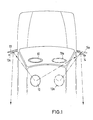
- Fig. 1 eine schematische Draufsicht eines Fahrzeugs mit zwei Außenspiegeln zur Verdeutlichung der Funktionen von fahrerseitigem und beifahrerseitigem Spiegel bei Fahrzeugen mit Rechtslenkung und Linkslenkung,
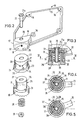
- Fig. 2 eine Explosionsdarstellung des einen Fahrzeugspiegels,
- Fig. 3 einen Längsschnitt durch das Gelenk des Fahrzeugspiegels,
- Fig. 4 einen Schnitt entlang der Linie IV-IV von Fig. 3 bei einem fahrerseitigen Rechtsspiegel, und
- Fig.5 die gleiche Darstellung wie Fig. 4 bei einem beifahrerseitigen Rechtsspiegel.
- 1 is a schematic plan view of a vehicle with two exterior mirrors to illustrate the functions of the driver-side and passenger-side mirrors in vehicles with right-hand drive and left-hand drive,
- 2 is an exploded view of a vehicle mirror,
- 3 shows a longitudinal section through the joint of the vehicle mirror,
- Fig. 4 is a section along the line IV-IV of Fig. 3 in a driver's right mirror, and
- 5 shows the same representation as FIG. 4 with a passenger-side right-hand mirror.
In Fig. 4 ist in durchgezogenen Linien das Lenkrad 10 bei einem Fahrzeug mit Linkslenkung dargestellt. Der Kopf des Fahrers ist mit 12 bezeichnet. Das Gehäuse des fahrerseitigen Spiegels 13 steht bei einem solchen Fahrzeug mit Linkslenkung nahezu rechtwinklig von der Fahrzeugkarosserie ab. Der Rechtsspiegel 14 hat eine größere Schrägstellung als der Linksspiegel 13, d.h. der Winkel, den das Spiegelgehäuse zur Fahrzeugkarosserie bildet, ist spitzer als beim Spiegel 13.In Fig. 4, the
Die gleichen Verhältnisse sind außerdem bei e inem Fahrzeug mit Rechtslenkung in Fig. 1 strichpunktiert dargestellt, wobei das Lenkrad 10a und der Kopf des Fahrers mit 12a bezeichnet sind. Man erkennt, daß hierbei das Gehäuse des Rechtsspiegels 14a nahezu senkrecht von der Fahrzeugkarosserie absteht, während das Gehäuse des Linksspiegels 13a, der den Beifahrerspiegel bildet, einen kleineren Anstellwinkel hat.The same relationships are also shown in dash-dot lines in a right-hand drive vehicle in FIG. 1, the
Das nachfolgend beschriebene Ausführungsbeispiel bezieht sich auf den Rechtsspiegel 14 bzw. 14a, dessen Gehäuse auf die beiden dargestellten Positionen eingestellt werden kann. In gleicher Weise kann entsprechend auch der Linksspiegel ausgebildet sein.The exemplary embodiment described below relates to the right-
In Fig. 2 ist von dem Spiegel 14 nur das Spiegelgehäuse 15 dargestellt; das Spiegelglas und der Spiegelglasträger sowie die Verstellvorrichtung zum Verstellen des Spiegelglases in Bezug auf das Spiegelgehäuse 15 sind aus Gründen der Übersichtlichkeit fortgelassen. Auch der äußere Rand des Spiegelgehäuses 15 ist nicht dargestellt. Der Verstellantrieb sowie das Schwenklager für den Spiegelglasträger sind an Befestigungseinrichtungen 16 im Innern des Spiegelgehäuses 15 befestigt.In Fig. 2, only the
Das Spiegelgehäuse 15 weist ein Lagerteil 17 mit einer zylindrischen Ausnehmung 18 mit vertikaler Achse auf. Die Ausnehmung 18 wird nach oben durch eine horizontale Wand 19 begrenzt, welche ein Loch 20 zum Hindurchstecken des Schaftes 21 aufweist. Der Schaft kann auch als Hohlniet ausgebildet sein. In diesem Fall würde die Mutter 29 entfallen. In die Ausnehmung 18 ragt von unten her das kappenförmige zylindrische Drehorgan 37 hinein, dessen obere Wand 22 sich von unten her gegen die Wand 19 legt. Das Drehorgan 37 weist am unteren Ende einen radial abstehenden Flansch 23 auf, der unter den Rand des Lagerteils 17 greift. In der Unterseite des Flansches 23 befinden sich radiale Nuten 24.The
Der starre am Fahrzeug montierte Spiegelfuß 25 ist mit einem aufragenden Zylinder 26 versehen, der passend in das Innere des Drehorgans 37 hineinragt und an seinem oberen Ende eine horizontale Wand 27 aufweist. Der Schaft 21 ragt durch miteinander fluchtende Löcher in den Wänden 19,22 und 27 hindurch und erstreckt sich in das Innere des Zylinders 26. Auf der Wand 19 ist der Schaft 21 mit einem Kopf 21a abgestützt. Eine den Schaft 21 im Innern des Zylinders 26 umgebende Schraubenfeder 28 drückt gegen die Unterseite der Wand 27 und stützt sich am entgegengesetzten Ende an einer Mutter 29 ab, die auf ein Gewinde des Schaftes 21 aufgeschraubt ist. Die Feder 28 drückt daher die Wände 27,22 und 19 axial gegeneinander.The
Der Spiegelfuß 25 ist am unteren Ende des Zylinders 26 mit einem radialen Flansch 30 versehen, an dessen Oberseite radiale Rippen 31 vorgesehen sind. Jede der Rippen 31 wird von einer der Nuten 24 des Drehorgans 37 aufgenommen. Durch die Wirkung der Feder 28 werden die Nuten 24 über die Rippen 31 gedrückt. Die Nuten 24 und die Rippen 31 bilden ineinandergreifende Rastelemente, die unter der Wirkung der Feder 28 gegeneinandergedrückt werden, um den Spiegel in seiner Position festzuhalten. Bei einem gegen das Spiegelgehäuse wirkenden Schlag können die Rastelemente ausrasten und das Spiegelgehäuse kann an die Fahrzeugkarosserie angeklappt werden.The
Zum Einstellen des Spiegels auf die beiden Positionen 14 und 14a ist die Einstellvorrichtung aus der Schraube 32 und den beiden Rastlöchern 33,34 vorgesehen. Die Schraube 32 ist in eine radiale Gewindebohrung der Wand des Lagerteils 17 eingeschraubt und ihr Ende ragt in eine der beiden Bohrungen 33 oder 34 des Drehorgans 21 hinein. Die Bohrungen 33 und 34 sind an dem Drehorgan 37 in gleicher Höhe angeordnet und sie haben einen Winkelabstand von etwa 15° voneinander. Wenn der Spiegel in der Position gemäß Fig. 4 als fahrerseitiger Spiegel benutzt wird, wird das Spiegelgehäuse relativ zu dem Drehorgan 21 so gedreht, daß die Achse der Schraube 32 mit derjenigen der Bohrung 33 fluchtet. Durch Festdrehen der Schraube 32 wird diese Position fixiert. Bei Benutzung des Spiegels als beifahrerseitiger Spiegel wird die Schraube 32 auf die Bohrung 34 eingestellt und in diese hineingeschraubt. Die Schraube 32 bildet also zusammen mit den Bohrungen 33 und 34 die Einstellvorrichtung zum Einstellen des Spiegelgehäuses 15 auf zwei verschiedene Schwenkstellungen.To adjust the mirror to the two
Zum leichteren Auffinden der Schwenkposition dient die Schwenkbegrenzungsvorrichtung 35,36. Diese besteht aus dem von der Oberseite des Flansches 23 des Drehorgans 37 aufragenden Stift 35 und der an der Unterseite der Wand des Lagerteils 17 vorgesehenen Umfangsnut 36. Der Stift 35 ragt in die Nut 36 hinein und ist in dieser verschiebbar. Die Enden der Nut 36 bilden Endanschläge. Wenn der Stift 35 gegen ein Ende der Nut 36 stößt, befindet sich die Schraube 32 in Ausrichtung mit einer der Bohrungen 33 oder 34.The
Wenn das Spiegelgehäuse 15 an die Karosserie angeklappt werden soll, rasten die Nuten 24 von den Stegen 31 aus. Beim anschließenden Zurückführen des Spiegelgehäuse in die Normalstellung rasten die Nuten wieder in den Stegen ein. Bei dem vorliegenden Ausführungsbeispiel ist die Möglichkeit des Einstellens des Spiegelgehäuses auf zwei verschiedene Winkelstellungen in Verbindung mit einem Abklappmechanismus beschrieben worden. Wenn ein Abklappmechanismus nicht vorhanden ist, ist die Einstellvorrichtung unmittelbar zwischen Spiegelfuß und Spiegelgehäuse wirksam, während sie bei Vorhandensein eines Abklappmechanismus zwischen dem rastend mit dem Spiegelfuß verbundenen Drehorgan 21 und dem Spiegelgehäuse wirksam ist. If the
Claims (4)
dadurch gekennzeichnet, daß zwischen dem Spiegelfuß (25) oder einem einrastend am Spiegelfuß festgelegten Drehorgan (37) und dem Spiegelgehäuse (15) eine feststellbare Einstellvorrichtung (32,33,34) vorgesehen ist, die eine Einstellung des Spiegelgehäuses (15) auf zwei verschiedene Schwenkstellungen ermöglicht.1. Vehicle exterior mirror with a mirror base (25) to be fastened to the vehicle and a mirror housing (15) which is attached to the mirror base (25) and can be pivoted about an essentially vertical axis and in which an adjustable mirror glass is arranged,
characterized in that a lockable adjusting device (32, 33, 34) is provided between the mirror base (25) or a rotating member (37) which is locked in position on the mirror base and which adjusts the mirror housing (15) to two different positions Allows swivel positions.
Applications Claiming Priority (2)
| Application Number | Priority Date | Filing Date | Title |
|---|---|---|---|
| DE19858533057 DE8533057U1 (en) | 1985-11-23 | 1985-11-23 | Vehicle exterior mirror |
| DE8533057U | 1985-11-23 |
Publications (2)
| Publication Number | Publication Date |
|---|---|
| EP0223923A2 true EP0223923A2 (en) | 1987-06-03 |
| EP0223923A3 EP0223923A3 (en) | 1988-05-18 |
Family
ID=6787535
Family Applications (1)
| Application Number | Title | Priority Date | Filing Date |
|---|---|---|---|
| EP86110687A Withdrawn EP0223923A3 (en) | 1985-11-23 | 1986-08-01 | Vehicle external rear-view mirror |
Country Status (2)
| Country | Link |
|---|---|
| EP (1) | EP0223923A3 (en) |
| DE (1) | DE8533057U1 (en) |
Cited By (7)
| Publication number | Priority date | Publication date | Assignee | Title |
|---|---|---|---|---|
| GB2186246B (en) * | 1986-02-10 | 1989-11-08 | Michael Zipperle | External rear view mirror for motor vehicles |
| US5073019A (en) * | 1989-01-10 | 1991-12-17 | Metagal Industria E Comercio Ltda. | External rear view mirror assembly for vehicles |
| US5205182A (en) * | 1991-02-04 | 1993-04-27 | Britax Rainsfords Pty Ltd | Cable actuated mirror tilt control |
| EP0644084A1 (en) * | 1993-09-03 | 1995-03-22 | Ichikoh Industries Limited | Rearview mirror system for vehicles |
| US5636071A (en) * | 1994-08-25 | 1997-06-03 | Murakami Kaimeido Co., Ltd. | Speed reduction device for an electrically powered foldable rearview mirror |
| US5639054A (en) * | 1994-11-02 | 1997-06-17 | United Technologies Automotive Systems, Inc. | Pivot mount for exterior side-mounted rearview mirror |
| CN102811886A (en) * | 2010-03-23 | 2012-12-05 | 戴姆勒股份公司 | Pair Of External Vehicle Mirrors |
Families Citing this family (2)
| Publication number | Priority date | Publication date | Assignee | Title |
|---|---|---|---|---|
| DE19922797B4 (en) * | 1999-05-18 | 2006-11-02 | Bayerische Motoren Werke Ag | Exterior rearview mirror for a motor vehicle |
| DE102008026039B4 (en) * | 2008-05-30 | 2012-12-13 | Ficosa International Gmbh | Rearview mirror and method for mounting a rearview mirror on a motor vehicle |
Citations (3)
| Publication number | Priority date | Publication date | Assignee | Title |
|---|---|---|---|---|
| DE3017228A1 (en) * | 1980-05-06 | 1981-11-12 | Bernhard Dipl.-Wirtsch.-Ing. 3002 Wedemark Mittelhäuser | EXTERNAL REAR VIEW MIRROR FOR MOTOR VEHICLES |
| EP0079677A1 (en) * | 1981-10-22 | 1983-05-25 | Britax (Wingard) Limited | Exterior rear view mirror |
| FR2570038A1 (en) * | 1984-09-12 | 1986-03-14 | American Safety Equip | REVERSIBLE REARVIEW MOUNT |
-
1985
- 1985-11-23 DE DE19858533057 patent/DE8533057U1/en not_active Expired
-
1986
- 1986-08-01 EP EP86110687A patent/EP0223923A3/en not_active Withdrawn
Patent Citations (3)
| Publication number | Priority date | Publication date | Assignee | Title |
|---|---|---|---|---|
| DE3017228A1 (en) * | 1980-05-06 | 1981-11-12 | Bernhard Dipl.-Wirtsch.-Ing. 3002 Wedemark Mittelhäuser | EXTERNAL REAR VIEW MIRROR FOR MOTOR VEHICLES |
| EP0079677A1 (en) * | 1981-10-22 | 1983-05-25 | Britax (Wingard) Limited | Exterior rear view mirror |
| FR2570038A1 (en) * | 1984-09-12 | 1986-03-14 | American Safety Equip | REVERSIBLE REARVIEW MOUNT |
Cited By (9)
| Publication number | Priority date | Publication date | Assignee | Title |
|---|---|---|---|---|
| GB2186246B (en) * | 1986-02-10 | 1989-11-08 | Michael Zipperle | External rear view mirror for motor vehicles |
| US5073019A (en) * | 1989-01-10 | 1991-12-17 | Metagal Industria E Comercio Ltda. | External rear view mirror assembly for vehicles |
| US5205182A (en) * | 1991-02-04 | 1993-04-27 | Britax Rainsfords Pty Ltd | Cable actuated mirror tilt control |
| EP0644084A1 (en) * | 1993-09-03 | 1995-03-22 | Ichikoh Industries Limited | Rearview mirror system for vehicles |
| US6132050A (en) * | 1993-09-03 | 2000-10-17 | Ichikoh Industries, Ltd. | Rearview mirror system for vehicles |
| US5636071A (en) * | 1994-08-25 | 1997-06-03 | Murakami Kaimeido Co., Ltd. | Speed reduction device for an electrically powered foldable rearview mirror |
| US5639054A (en) * | 1994-11-02 | 1997-06-17 | United Technologies Automotive Systems, Inc. | Pivot mount for exterior side-mounted rearview mirror |
| CN102811886A (en) * | 2010-03-23 | 2012-12-05 | 戴姆勒股份公司 | Pair Of External Vehicle Mirrors |
| US9079538B2 (en) | 2010-03-23 | 2015-07-14 | Daimler Ag | Pair of external vehicle mirrors |
Also Published As
| Publication number | Publication date |
|---|---|
| EP0223923A3 (en) | 1988-05-18 |
| DE8533057U1 (en) | 1986-01-09 |
Similar Documents
| Publication | Publication Date | Title |
|---|---|---|
| DE4211674C2 (en) | Steering column with a safety link for a motor vehicle equipped with an inflatable gas bag in the steering wheel | |
| DE19934739B4 (en) | Steering device for a vehicle | |
| DE7833365U1 (en) | CLAMPING DEVICE FOR HOLDING AN ADJUSTABLE CONTROL COLUMN FOR A MOTOR VEHICLE | |
| EP0223923A2 (en) | Vehicle external rear-view mirror | |
| DE3016212A1 (en) | LENGTH AND TILT ADJUSTABLE STEERING COLUMN FOR A VEHICLE | |
| DE19636719A1 (en) | Steerable rigid axle for vehicle | |
| DE19613581A1 (en) | Horizontal adjustment device of an adjustment unit for a rearview mirror | |
| EP3332995B1 (en) | Draw-bar for a vehicle trailer | |
| EP0221255A2 (en) | Vehicle rear view mirror | |
| EP0092665B1 (en) | Catching device for the arm of a lorry rearview mirror | |
| EP0437695A1 (en) | Auxiliary external mirror for motor vehicles | |
| DE102019131595B4 (en) | vehicle seat | |
| EP0802083A2 (en) | Exterior rearview mirror | |
| EP0901927B1 (en) | Fuel tank inlet cover for motor vehicles | |
| DE2426489A1 (en) | Remote controlled wing mirror - has spring-back safety joint between mirror and mounting socket | |
| DE3605945C2 (en) | Exterior rear view mirror for motor vehicles | |
| DE2752818C2 (en) | ||
| DE3339436A1 (en) | Device for adjusting the position of a vehicle seat | |
| DE2303688A1 (en) | REVIEW MIRROR | |
| DE10027202A1 (en) | Gear unit for adjusting angle between two parts has gear wheel segment in seat fitting engaging first segment on back rest and carrying rocker bolt protruding into groove in rotary disc | |
| EP0004329A1 (en) | Additional rear mirror for motor vehicles | |
| DE2600747A1 (en) | ADJUSTMENT DEVICE FOR ADJUSTING THE HEADLIGHTS OF A MOTOR VEHICLE | |
| DE2616912A1 (en) | DEVICE FOR FASTENING THE DEFLECTION SYSTEM ON THE NECK OF AN ELECTRON BEAM TUBE | |
| DE10256899B4 (en) | Backrest escapement for seats | |
| DE2751878A1 (en) | External rear view driving mirror - has upper and lower sections with separate housings rotated relative to each other to provide desired field of view |
Legal Events
| Date | Code | Title | Description |
|---|---|---|---|
| PUAI | Public reference made under article 153(3) epc to a published international application that has entered the european phase |
Free format text: ORIGINAL CODE: 0009012 |
|
| AK | Designated contracting states |
Kind code of ref document: A2 Designated state(s): AT DE FR GB IT NL SE |
|
| PUAL | Search report despatched |
Free format text: ORIGINAL CODE: 0009013 |
|
| AK | Designated contracting states |
Kind code of ref document: A3 Designated state(s): AT DE FR GB IT NL SE |
|
| 17P | Request for examination filed |
Effective date: 19881028 |
|
| STAA | Information on the status of an ep patent application or granted ep patent |
Free format text: STATUS: THE APPLICATION HAS BEEN WITHDRAWN |
|
| 17Q | First examination report despatched |
Effective date: 19900918 |
|
| 18W | Application withdrawn |
Withdrawal date: 19901018 |
|
| RIN1 | Information on inventor provided before grant (corrected) |
Inventor name: LUCHTENBERG, CURT |