EP0232183A2 - Retrievable gravel packer - Google Patents
Retrievable gravel packer Download PDFInfo
- Publication number
- EP0232183A2 EP0232183A2 EP87301052A EP87301052A EP0232183A2 EP 0232183 A2 EP0232183 A2 EP 0232183A2 EP 87301052 A EP87301052 A EP 87301052A EP 87301052 A EP87301052 A EP 87301052A EP 0232183 A2 EP0232183 A2 EP 0232183A2
- Authority
- EP
- European Patent Office
- Prior art keywords
- mandrel
- packer
- packing
- wedge
- shoe
- Prior art date
- Legal status (The legal status is an assumption and is not a legal conclusion. Google has not performed a legal analysis and makes no representation as to the accuracy of the status listed.)
- Ceased
Links
Images


Classifications
-
- E—FIXED CONSTRUCTIONS
- E21—EARTH DRILLING; MINING
- E21B—EARTH DRILLING, e.g. DEEP DRILLING; OBTAINING OIL, GAS, WATER, SOLUBLE OR MELTABLE MATERIALS OR A SLURRY OF MINERALS FROM WELLS
- E21B33/00—Sealing or packing boreholes or wells
- E21B33/10—Sealing or packing boreholes or wells in the borehole
- E21B33/12—Packers; Plugs
- E21B33/129—Packers; Plugs with mechanical slips for hooking into the casing
- E21B33/1294—Packers; Plugs with mechanical slips for hooking into the casing characterised by a valve, e.g. a by-pass valve
-
- E—FIXED CONSTRUCTIONS
- E21—EARTH DRILLING; MINING
- E21B—EARTH DRILLING, e.g. DEEP DRILLING; OBTAINING OIL, GAS, WATER, SOLUBLE OR MELTABLE MATERIALS OR A SLURRY OF MINERALS FROM WELLS
- E21B23/00—Apparatus for displacing, setting, locking, releasing, or removing tools, packers or the like in the boreholes or wells
- E21B23/06—Apparatus for displacing, setting, locking, releasing, or removing tools, packers or the like in the boreholes or wells for setting packers
-
- E—FIXED CONSTRUCTIONS
- E21—EARTH DRILLING; MINING
- E21B—EARTH DRILLING, e.g. DEEP DRILLING; OBTAINING OIL, GAS, WATER, SOLUBLE OR MELTABLE MATERIALS OR A SLURRY OF MINERALS FROM WELLS
- E21B33/00—Sealing or packing boreholes or wells
- E21B33/10—Sealing or packing boreholes or wells in the borehole
- E21B33/12—Packers; Plugs
- E21B33/129—Packers; Plugs with mechanical slips for hooking into the casing
- E21B33/1295—Packers; Plugs with mechanical slips for hooking into the casing actuated by fluid pressure
-
- E—FIXED CONSTRUCTIONS
- E21—EARTH DRILLING; MINING
- E21B—EARTH DRILLING, e.g. DEEP DRILLING; OBTAINING OIL, GAS, WATER, SOLUBLE OR MELTABLE MATERIALS OR A SLURRY OF MINERALS FROM WELLS
- E21B43/00—Methods or apparatus for obtaining oil, gas, water, soluble or meltable materials or a slurry of minerals from wells
- E21B43/02—Subsoil filtering
- E21B43/04—Gravelling of wells
Landscapes
- Life Sciences & Earth Sciences (AREA)
- Engineering & Computer Science (AREA)
- Geology (AREA)
- Mining & Mineral Resources (AREA)
- Physics & Mathematics (AREA)
- Environmental & Geological Engineering (AREA)
- Fluid Mechanics (AREA)
- General Life Sciences & Earth Sciences (AREA)
- Geochemistry & Mineralogy (AREA)
- Consolidation Of Soil By Introduction Of Solidifying Substances Into Soil (AREA)
- Piles And Underground Anchors (AREA)
- Earth Drilling (AREA)
Abstract

Description
- This invention relates generally to systems for gravel packing a production zone of a well, and more particularly, to a retrievable gravel packer for use in such a system.
- Unconsolidated formations, particularly those containing loose sands and sandstone strata, present constant problems in well production due to migration of loose sands and degraded sandstone into the well bore as the formation deteriorates under the pressure and flow of fluids therethrough. This migration of particles may eventually clog the flow passages in the production system of the well, and can seriously erode the equipment. In some instances, the clogging of the production system may lead to a complete cessation of flow, or killing of the well.
- One method of controlling sand migration into a well bore consists of placing a pack of gravel on the exterior of a perforated or slotted liner or screen which is positioned across an unconsolidated formation to present a barrier to the migrating sand from that formation while still permitting fluid flow. The gravel is carried to the formation in the form of a slurry, the carrier fluid being removed and returned to the surface. The proper size of gravel must be employed to effectively halt sand miqration through the pack, the apertures of the liner or screen being gauged so that the gravel will settle out on its exterior, with the slurry fluid carrying the gravel entering the liner or screen from its exterior and being circulated back to the surface.
- Prior to effecting the gravel pack, drilling mud and other contaminants may be washed from the well bore, and the formation treated. Commonly employed treatments include acidizing to dissolve formation clays, and injecting stabilizing gels to prevent migration of formation components and formation breakdown prior to packing.
- Subsequent to effecting the gravel pack, a reverse circulation technique may be utilized to remove remaining gravel laden slurry from the operating string utilized to conduct the slurry. With such a reverse circulation technique, the direction of circulation is reversed and a clean fluic is pumped down the path previously utilized for returning the slurry fluid, and the remaining gravel laden slurry will be forced back up the path originally used to conduct the gravel laden slurry down to the well.
- A typical prior art retrievable gravel packer is disclosed in U. S. Patent No. 4,049,055 to Brown and assigned to the Brown Oil Tools, Inc. Brown discloses a hydraulic set
retrievable gravel packer 10 which has its expandable packing element, its upper and lower packing shoes, its slip elements, and its upper and lower wedges arranged in a fashion somewhat similar to that of the gravel packer of the present invention. The Brown gravel packer differs substantially from that of the present invention in several areas. One of the most significant distinctions is that Brown does not disclose a non-rotational connecting means connected between the mandrel and each of the upper and lower shoes and upper and lower wedges for preventing rotation of those elements relative to the mandrel. Additionally, the releasing mechanism utilized in the Brown gravel packer is substantially different from that of the present invention. - Another typical prior art retrievable well packer is shown in U. S. Patent No. 3,678,998 to Cockrell et al. and assigned to Baker Oil Tools, Inc. The Cockrell et al. packer is a wireline set packer. Although the components of the Cockrell et al. packer are arranged in a considerably different manner than is the present invention, Cockrell et al. does disclose in FIG. lc thereof pins 67 and 69 slidably received in a
slot 68, which appear to hold the mandrel of the packer against relative rotation relative to the upper and lower packer shoes and the upper wedge. There does not, however, appear to be any non-rotational connection between the mandrel and the lower wedge. - U. S. Patent No. 3,987,854 to Callihan et al., and assigned to Baker Oil Tools, Inc., appears to be in some aspects similar to the disclosure of Patent No. 3,678,998 just discussed above, although it does not disclose the use of pins received in slots as did Patent No. 3,678,998. The Callihan et al. '854 patent, however, is disclosed in the context of a hydraulically set gravel packing system.
- Another typical prior art hydraulically set gravel packer is disclosed in U. S. Patent No. 4,180,132 to Young, and assigned to Otis Engineering Corporation.
- The present invention provides a retrievable gravel packer having an expandable packing means disposed about a packer mandrel.
- Upper and lower shoe means are received about the mandrel above and below the packing means for compressibly engaging the upper and lower ends of the packing means.
- A slip means is also received about the mandrel for anchoring the packer apparatus within a well bore. Upper and lower wedge means are received about the mandrel above and below the slip means for wedging the slip means radially outward upon compression of the packing means.
- A non-rotational connecting means is operatively connected between the mandrel and each of the upper shoe means, lower shoe means, upper wedge means, and lower wedge means for preventing rotation of those components relative to the mandrel in the event the packer apparatus . has to be milled out of a well bore.
- The packer also includes a selective releasing means operatively associated with the mandrel and the lower wedge for releasing the packing means from an expanded position. The selective releasing means can include a releasing collet attached to the lower end of the mandrel and having lugs thereof received in a groove of the lower wedge thus longitudinally locking the mandrel relative to the lower wedge. Preferably, a releasing sleeve is initially releasably held in a lower position within the releasing collet to hold the locking lugs in the groove of the lower shoe. This releasing sleeve is movable to an upper position relative to the releasing collet to allow collet spring fingers of the collet to deflect radially inward to disengage the mandrel from the lower wedge means.
- In order that the invention may be more fully understood, one embodiment thereof will now be described by way of illustration only, with reference to the accompanying drawings, wherein:
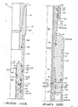
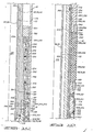
- FIGS. lA-lH comprise en elevation right-side only sectioned view of the embodiment of gravel packing system of the present invention. In FIG. 1A, the setting device is shown with its upper end attached to a lower end of a work string and with its lower end in place within a liner hanger and a liner valve means of a liner string, with all of the structures in the positions they would normally be in when the work string, setting device and liner string are initially assembled.
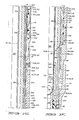
- FIGS. 2A-2B comprise an elevation sectioned view of-the packer or liner hanger of the gravel packing system of the present invention.
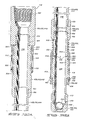
- FIGS. 3A-3B comprise an elevation sectioned view of a retrieving apparatus for retrieving the liner hanger of FIGS. 2A and 2B.
- FIGS. 4,5 and 6 are a sequential series of illustrations of the retrieving apparatus of FIGS. 3A-3B in operative engagement with the packer apparatus of FIGS. 2A-2B.
- FIG. 4 shows the retrieving apparatus after it has been inserted within the packing apparatus and is ready to release the packing apparatus.
- FIG. 5 shows the retrieving apparatus moved upward relative to the packing apparatus. The releasing sleeve has been pulled upward to a position wherein further upward motion of the retrieving apparatus will cause the packer apparatus to be released.
- FIG. 6 illustrates the use of a differential area piston of the releasing collet of the retrieving apparatus to release the retrieving apparatus from the packer apparatus in the event that the packer apparatus is stuck in the well and cannot be released by the retrieving apparatus.
- Referring now to the drawings and particularly to FIGS. 1A-1H, the gravel packing system of the present invention is shown and generally designated by the
numeral 10. - As shown in FIG. lA, the
system 10 includes a setting device generally designated by thenumeral 12 which is attached to a lower end of awork string 14 at threadedconnection 16. - As seen in FIGS. 1C-1H, the
setting device 12 is assembled with a packer apparatus generally designated by thenumeral 18. Thepacker apparatus 18 is often referred to as a liner hanger because it initially serves to hang a liner string within a well bore. - As seen in FIG. 1F, the
system 10 also includes a liner valve means 20 connected to a lower end ofpacker apparatus 18 at threadedconnection 22. - As seen in FIG. 1H, the
system 10 also includes agravel packing screen 24 which is only schematically illustrated. Thescreen 24 is connected to a lower end of liner valve means 20 at threadedconnection 26. - As is also shown in FIG. IH, the
system 10 includes atail pipe 28 connected to a lower end of settingdevice 12 at threadedconnection 30. - The packer apparatus or
liner hanger 18, the liner valve means 20, and thescreen 24 may be collectively referred to as a liner string. - The
setting device 12 includes a housing 32 comprised of an outer housing assembly 34, a lower inner housing assembly 36, and a central flow tube 38. - The outer housing assembly 34 includes a return valve housing section 40, a piston adapter housing section 42, a connectinq collet housing section 44, a packer housing section 46, a supply valve housing section 48, a liner valve housing section 50, and a check valve housing section 52.
- Return valve housing section 40 and piston adapter housing section 42 are threadedly connected at threaded
connection 54 with a seal beinq provided therebetween by 0-ring 56. - The connecting collet housing section 44 and piston adapter housing section 42 are connected together at threaded
connection 58 with a seal being provided therebetween by 0-ring 60. - The packer housing section 46 and connecting collet housing section 44 are connected together at threaded con-
nection 62 with a seal being provided therebetween by 0-ring 64. - The supply valve housing section 48 and packer housing section 46 are connected together at threaded
connection 66 with a-seal being provided therebetween by O-ring 68. - The liner valve housing section 50 and supply valve housing section 48 are connected together at threaded
connection 70 with a seal being provided therebetween by 0-ring 72. - The check valve housing section 52 and liner valve housing section 50 are connected together at threaded
connection 74 with a seal being provided therebetween by 0-ring 76. - The lower inner housing assembly 36 includes an upper member 78 and a lower member 80 connected together at threaded
connection 82. - The lower inner housing assembly 36 is centrally received within the outer housing assembly 34 and fixedly attached thereto by
weld 86. - The housing 32 has a gravel packing port 88 disposed through a wall thereof. The gravel packing port 88 includes an inner portion 90 disposed through upper member 78 of lower inner housing assembly 36, and an outer portion 92 disposed through supply valve housing section 48 of outer housing assembly 34. The inner and outer portions 90 and 92 are in registry with each other, and the
weld 86 circumscribes the junction between inner and outer portions 9t and 92 of gravel packing port 88. - The central flow tube 38 of housing 32 has an
upper end 94 sealingly received in anupper bore 96 of return valve housing section 40 of outer housing assembly 34 with a seal being provided therebetween by 0-ring 98. - Central flow tube 38 has a
lower end 100 sealingly received in abore 102 of upper member 78 of lower inner housinq assembly 36 with a seal being provided therebetween by 0-ring 104. - The housing 32 has a
slurry supply passage 106 and afluid return passage 108 defined therein. - ,A majority portion of the
slurry supply passage 106 is defined by abore 110 of the central flow tube 38. - The
fluid return passage 108 is for the most part an annular fluid return passage, and a majority portion of thereturn passage 108 is defined between anouter surface 112 of the central flow tube 38 and the outer housing assembly 34. - The gravel packing port 88 of housing 32 extends transversely throuqh, but is isolated from, the
annular return passage 108. - The
setting device 12 includes a weight responsive return valve means 114 (see FIGS. lA-lB) operatively associated with theouter housing assembly 134 of housing 32 for communicating an upper portion 116 offluid return passage 108 with a well annulus exterior of the housing 32 in response to reciprocation of thework string 14. - The return valve means 114 includes a
return valve sleeve 118 slidably disposed about an outercylindrical surface 120 of return valve housing section 40. Thereturn valve sleeve 118 has asleeve port 122 disposed therethrough. - The return valve housing section 40 has a
housing port 124 disposed therethrough, which may be considered to be a part of the return valve means 114. Thehousing port 124 is communicated with the upper portion 116 ofreturn passage 108. - An
upper adapter 126 is threadedly connected to returnvalve sleeve 118 at threadedconnection 128 with a seal being provided therebetween by O-ring 130. Theupper adapter 126 provides a connecting means for connecting an upper end of thesetting device 12 to thework string 14 at threadedconnection 16 previously mentioned. - Return valve means 114 further includes a
splined connector cap 132 threadedly connected to returnvalve sleeve 118 at threadedconnection 134.Connector cap 132 includes a plurality of radially inward extendingsplines 136 which are meshed with a plurality of radially outward extendingsplines 138 of return valve housing section 40 so that relative longitudinal movement ofreturn valve sleeve 118 relative to outer housing assembly 34 is permitted, while relative rotational movement therebetween is prevented. - In FIGS. lA-lB, the return valve sleeve is shown in an uppermost closed position relative to outer housing assembly 34. This uppermost position is defined by abutment of an
upper end 140 ofconnector cap 132 with a downward facingannular shoulder 142 of return valve housing section 40. - Return valve means 114 includes first, second and third 0-ring seal means 144, 146 and 148, respectively, for sealing between return valve housing section 40 and return
valve sleeve 118. - When
return valve sleeve 118 is in its uppermost closed position relative to outer housing assembly 34, thesleeve port 122 is located betweenseals housing port 124 is located betweenseals sleeve port 122 is isolated fromhousing port 124. - When weight is set down upon the
setting device 12 by means of thework string 14, thereturn valve sleeve 118 will move downward to a lower position relative to outer housinq assembly 34 in which thesleeve port 122 is in registry with thehousing port 124 so as to communicate thereturn passage 108 with the well annulus exterior of thesetting device 12. - The
setting device 12 further includes a hydraulic setting piston means 150, operatively associated with the housing 32 and communicated with thecentral supply passage 106 for setting thepacker apparatus 18 of thegravel packing system 10 in response to a first increase in fluid pressure in thesupply passage 106 to a first value. - The
setting piston 150 has abore 152 and a counterbore 15-4 within which are closely received cylindricalouter surfaces - A smaller diameter O-
ring seal 160 carried bypiston 150 seals against connecting collet housing section 44, and a larqer diameter seal 162 seals between piston adapter housing section 44 andcounterbore 154. The effective differential area ofsetting piston 150 is defined betweenseals - An
annular power chamber 164 is defined between connecting collet housing section 44 of outer housing assembly 34 of housing 32 and thesetting piston 150. - Housing 32 includes a transverse passage 166 which communicates
central supply passage 106 with theannular power chamber 164. - Transverse passage 166 includes a first portion 168 disposed radially through an
enlarged diameter portion 172 of central flow tube 38, and a second portion 170 disposed through connecting collet housing section 44. - The first and second portions 168 and 170 are in registry with each other and a
weld 174 circumscribes the junction therebetween. - Thus, the transverse passage 166 extends transversely throuah, but is isolated from, the
annular return passage 108. - Fluid pressure from within
central supply passage 106 is tranferred through transverse passage 166 to theannular power chamber 164 above settingpiston 150, so that thesetting piston 150 can be forced downward relative to housing 32 in response to an increase in pressure within thesupply passage 106 to a predetermined first value. - A cylindrical
tubular setting sleeve 176 is connected to the lower end of settingpiston 150 at threadedconnection 178. Arelief port 180 is disposed throughsleeve 176. - Setting
sleeve 176 has alower end 182 arranged for enqagement with thepacker apparatus 18 to set thepacker apparatus 18 in a manner that will be further described below. - Setting
sleeve 176 is initially retained in position relative to thepacker apparatus 18 by a plurality of shear pins 184 disposed through thesleeve 176 and received in anannular groove 186 of thepacker apparatus 18. - The
setting device 12 also includes a hydraulically actuated supply valve means 188 operatively associated with the lower inner housing assembly 36 of housing 32 for communicating the gravel packing port 88 of housing 32 with thecentral supply passage 106 of housing 32 in response to a second increase in fluid pressure in thecentral supply passage 106 to a second value greater than the previously mentioned first value. - The supply valve means 188 includes a sliding
supply valve sleeve 190 having an opencentral passageway 192 extending therethrough and open at both alower end 194 and anupper end 196 ofsupply valve sleeve 190. The opencentral passageway 192 ofsupply valve sleeve 190 is communicated with the centralslurry supply passage 106. - An
annular seat 198 circumscribes an upper end of opencentral passageway 192 for receiving aclosure ball 200 therein. - A retaining
cage 202 is disposed inbore 102 of upper member 78 of lower inner housing assembly 36 to keep theclosure ball 200 in place near thesupply valve sleeve 190. - An 0-
ring 203 seals between upper member 78 of lower inner housing assembly 36 andsupply valve sleeve 190. - When fluid pressure is increased in the central
slurry supply passage 106, a downward pressure differential acrossclosure ball 200 causesball 200 to seal onseat 198 so that a downward pressure differential is imposed onsupply valve sleeve 190. - The
supply valve sleeve 190 is initially retained in an upper closed position relative to lower inner housing assembly 36 by one or more shear pins 204 as seen in FIG. 1G. - When fluid pressure within central
slurry supply passage 106 reaches a predetermined value, the downward force exerted onsupply valve sleeve 190 will shear thepins 204 and thesupply valve sleeve 190 will move down to a lower open position defined by abutment oflower end 194 ofsupply valve sleeve 190 with a radially inward extendingflange 206 of lower member 80 of lower inner housing assembly 36. - When
supply valve sleeve 190 is in this lower position, an O-ring 207 seals between upper member 78 of lower inner housing assembly 36 andsupply valve sleeve 190 below the gravel packing port 88. - The shear pins 204 can generally be referred to as a releasable retaining means 204, operatively associated with the
supply valve sleeve 190 and the lower inner housing assembly 36 of housing 32, for initially retaining thesupply valve sleeve 190 in a closed position blocking the qravel packing port 88. - When the
supply valve sleeve 190 is moved downward to its lower open position, a locking means 208, operatively associated with thesupply valve sleeve 190 and the lower inner housing assembly 36 of housing 32 locks thesupply valve sleeve 190 in its lower open position. Locking means 208 includes a plurality of separate locking dogs 210 surrounded by an annular resilient band 212 which biases the dogs 210 radially inward. As seen in FIG. 1G, the locking dogs 208 are initially located within agroove 214 defined between upper and lower members 78 and 80 of lower inner housing assembly 36. - When the
supply valve sleeve 190 is moved downward relative to lower inner housing assembly, the locking dogs 210 will move radially inward into engagement with agroove 214 ofsupply valve sleeve 190 thus preventingsupply valve sleeve 190 from moving back upward. -
Supply valve sleeve 190 has a run-in fill port 216 disposed through a wall thereof.Port 216 communicates with gravel packing port 88, whensleeve 190 is in its initial upper position, to allow thework string 14 to fill with well fluid as thegravel packing system 10 is lowered into a well. The well fluid flows in through gravel packing port 88 and fillport 216, then up aroundball 200 and throughsupply passage 106. Well fluid can also enter throughscreen 24 to fill thework string 14. - When
supply valve sleeve 190 is in its lowermost open position, the run-in fill port 216 throughsupply valve sleeve 190 is communicated with aport 218 disposed through upper member 78 of lower inner housing assembly 36 to aid in the flow of clean fluid fromreturn passage 108 to supplypassage 106 during reverse circulation. This also provides a safety feature in the event the check valve ball 224 were to become stuck against the open lower end of lower member 80 of lower inner housing assembly 36, or in the event the open lower end of lower member 80 became plugged in some other manner. - The
setting device 12 further includes a check valve means 220, disposed in a lower portion of the housing 32 below the supply valve means 188 for permitting flow of return fluid upward therethrough and for preventing downward flow therethrough. - The check valve means 220 includes an annular check valve seat 222 and a check valve ball 224.
- The annular check valve seat 222 circumscribes an upper end of a
central bore 226 of check valve housing section 52.Bore 226 defines a portion of thereturn passage 108 of housing 32. - As will be further explained below, the check valve means 220 provides a means for directing reverse circulation fluid traveling down through those portions of
return passage 108 above check valve means 220, up through the opencentral passageway 192 ofsupply valve sleeve 190 and up through the centralslurry supply passage 106 of housing 32 to remove excess slurry from the settingdevice 12. - Setting
device 12 includes a releasable connecting means 268 operatively associated with connecting collet housing section 44 for releasably connecting thesetting device 12 to an internal left-handed thread 266 ofpacker apparatus 18. - Prior to lowering the
work string 14, settingdevice 12,packer apparatus 18, liner valve means 20 andscreen 24 into a well, the releasable connecting means 268 will be connected to thepacker apparatus 18 as shown in FIG. 1C. - The releasable connecting means 268 includes an upper collet ring portion 270 having a plurality of connecting
collet spring fingers 272 extending downward therefrom. Each of thespring fingers 272 includes a radially outer left-hand threadedsurface 274 for threadedly engaging the internal left-hand threadedsurface 266 of thepacker apparatus 18. - A plurality of
lugs 276 extend radially outward from connecting collet housing section 44 through the spaces between adjacent connectingcollet spring fingers 272 so that the releasable connecting collet means 268 is rotationally fixed relative to the connecting collet housing section 44. - Some longitudinal movement of releasable connecting col-let 268 relative to connecting collet housing section 44 is permitted. A
bore 278 of ring portion 270 is slidably received about an outercylindrical surface 280 of connecting collet housing section 44. Alimit ring 282 is threadedly connected to connecting collet housing section 44 above outercylindrical surface 280 at threadedconnection 284. Thelimit ring 282 limits upward movement of releasable connecting collet 268 relative to connecting collet housing section 44. An upward facingannular shoulder 286 of connecting collet housing section 44 will abut ring portion 270 of releasable connecting collet 268 to limit downward movement of connecting collet 268 relative to connecting collet housing section 44. - In FIG. lC, the ring portion 270 of collet 268 is shown abutting the
limit ring 282 as it would when thesetting device 12 is stabbed into thepacker apparatus 18 to make up the left-hand threads gravel packing system 10 is being lowered into the well, thepacker apparatus 18 and collet 268 will drop down relative to housing 32 of settingdevice 12 until ring portion 270 abutsshoulder 286. In that position, the lower portions offingers 272 engage an enlarged diameterouter surface 283 of connecting collet housing section 44 to prevent thefingers 272 from being biased inward. - As is further described below, after the
packing apparatus 18 has been set in a well bore, the settingdevice 12 is disconnected from packingapparatus 18 by right-hand rotation of thework string 14 and settingdevice 12 which disconnects the left-hand threadedouter surfaces 274 of connectingcollet spring fingers 272 from the internal left-handed thread 266 of packingapparatus 18. - As seen in FIGS. 1F-1G, the liner valve means 20 of the
gravel packing system 10 has a lower portion of the housing 32 of settingdevice 12 received therein so that the gravel packing port 88 of thesetting device 12 is in vertical registry with aliner valve port 228 of liner valve means 20. - The liner valve means 20 includes a liner valve body 230 and a liner valve sleeve 232 slidably disposed in the liner valve body 230.
- The .liner valve body 230 includes an upper body section 234 and a lower body section 236 connected together at threaded
connection 238 with a seal being provided therebetween by O-ring 240. An O-ring seal 229 seals between abore 231 of upper body section 234 and an outer surface 233 of supply valve housing section 48. - The
liner valve port 228 is disposed through the upper body section 234. - The liner valve sleeve 232 is operably associated with the liner valve housing section 50 of outer housing assembly 34 of housing 32 so that when the housing 32 is received in the liner valve means 20 as seen in FIGS. 1F-1H, the liner valve sleeve 232 is located below the
liner valve port 228, so that the gravel packing port 88 of housing 32 is communicated with theliner valve port 228. - The liner valve sleeve 232 includes a cylindrical tubular sealing portion 242 having first and second longitudinally spaced O-
ring seals spring collet fingers 248, each having alower head 250 including both a radially inward extendinglug 252 and a radially outward extendinglug 254. - The
setting device 12 and liner valve means 20 are so arranged and constructed that when the housing 32 of settingdevice 12 is received within the liner valve means 20 with the gravel packing port 88 in registry with theliner valve port 228, thespring collet fingers 248 are cammed radially inward as seen in FIGS. 1G and 1H so that the inward extendinglugs 252 are latched in an annularouter groove 256 of liner valve housing section 50 of housing 32 so that the liner valve sleeve 232 is releasably longitudinally fixed relative to the housing 32. - When the housing 32 of setting
device 12 is later withdrawn from the liner valve means 20, the liner valve sleeve 232 is pulled upward with the housing 32 relative to the liner valve body 230 until the liner valve sleeve reaches an upper closed position whereinliner valve port 228 is located longitudinally between 0-ring seals liner valve port 228. When the liner valve sleeve 232 is in this upper closed position, thespring collet fingers 248 spring radially outward to disengage from the liner valve housing section 50 of housing 32 and to engage a radially inward facingannular groove 258 defined between upper and lower body sections 234 and 236 of liner valve body 230 to thus releasably latch the liner valve sleeve 232 in its upper closed position blocking theliner valve port 228. - The
packer apparatus 18 is shown by itself in FIGS. 2A-2B, and is shown assembled with thesetting device 12 andliner valve apparatus 20 in FIGS. 1C-1F. - The
packer apparatus 18 includes a packer mandrel means 260. - A
mandrel connecting sleeve 262 is threadedly connected to packer mandrel means 260 at threadedconnection 264. -
Mandrel connecting sleeve 262 includes an internal left-handed thread 266. - The
groove 186 ofpacker apparatus 18 within which the shear pins 184 are received to initially retain settingsleeve 176 of settingdevice 12 in position relative to thepacker apparatus 18 is defined within an outer surface of themandrel connecting sleeve 262. -
Packer apparatus 18 includes an expandable packing means 286 including first, second and third annular packing elements 288, 290 and 292 disposed about the mandrel means 260. - An upper shoe means 294 is received about the mandrel means 260 above the packing means 286 for compressibly engaging an
upper end 296 of packing means 286. - A lower shoe means 298 is received about mandrel means 260 for compressibly engaging a lower end 300 of packing means 286.
- A slip means 302 is received about mandrel means 260 for anchoring the
packer apparatus 18 within a well bore. - An upper wedge means 304 is received about mandrel means 260 above the slip means 302 for wedging the slip means 302 radially outward upon longitudinal compression of the packing means 286.
- A lower wedge means 306 is also received about the mandrel means 260 below the slip means 302 for wedging the slip means 302 radially outward upon longitudinal compression of packing means 286.
- A non-rotational connecting means 308 is operatively connected between the mandrel means 260 and each of the upper shoe means 294, lower shoe means 298, upper wedge means 304, and lower wedge means 306 for preventing rotation of each of the upper shoe means 294, lower shoe means 298, upper wedqe means 304 and lower wedge means 306 relative to the mandrel means 260. As is further explained below, one important purpose of the non-rotational connecting means 308 is to prevent rotation of the various elements of the packer means 18 if the packer means 18 becomes stuck in a well bore and must be milled out of the well bore. As will be understood by those skilled in the art, if the various elements of the packer means 18 are allowed to rotate, it can be very difficult to mill the
packer apparatus 18 out of the well bore. - The non-rotational connecting me.ans 308 includes first, second and third radially inward extending pins or lugs 310, 312 and 314, respectively, which are slidably received in first, second and third longitudinally extending slots 316, 318 and 320, respectively, disposed in the mandrel means 260.
- As seen in FIG. lD, the lower shoe means 298 and the upper slip means 304 are separable non-integral structures which are fixedly connected together at threaded
connection 322 so as to be longitudinally fixed relative to each other. This provides a combined lower shoe and upper wedge means 324. - The combined lower shoe and upper wedge means 324 in- cludes a plurality of shear pins (not shown), rotationally offset from the pins 312, which initially retain the com- bined lower shoe and upper wedge means 324 in place relative to the mandrel means 260. These shear pins engage flat bot- tom holes (not shown) in mandrel means 260, and are designed to prevent the packer means 18 from prematurely setting as it is run into the well.
- An upper portion 326 of upper wedge means 304 and particularly an upper annular surface 328 thereof which engages the lower end 300 of packing means 286 can be generally referred to as being a portion of the lower shoe means 298 which compressibly engages the lower end 300 of packing means 286.
- The upper shoe means 294 includes a main shoe housing member 330 having an
inner bore 332 slidably received about an outercylindrical surface 334 of mandrel means 260. - The main shoe housing member 330 has a tapered wedging
shoulder 336 defined on an upper end thereof. - Main shoe housing member 330 includes a lower
annular end surface 338 compressibly engaging theupper end 296 of packing means 286. - Also, main shoe housing member 330 includes threaded upper and lower cylindrical
outer surfaces - Upper shoe means 294 also includes a dog housing 344 having a cylindrical portion 346 threadedly connected to threaded upper
outer surface 340 of main shoe housing member 330. - Dog housing 344 also includes an
annular flange 348 extending radially inward from an upper end of the cylindrical portion 346. - A
dog receiving groove 350 is defined within upper shoe means 294 by theflange 348, the cylindrical portion 346, and the tapered wedgingshoulder 336. - Upper shoe means 294 also includes an annular upper shoe ring 352 threadedly connected to threaded lower
outer surface 342 of main shoe housing member 330. The upper shoe ring 352 has a lowerannular surface 354 substantially flush with thelower end surface 338 of main shoe housing member 330 and compressibly engaged with theupper end 296 of packinq means 286. - The
packer apparatus 18 also includes a locking means 356, operatively associated with the mandrel means 260 and the upper shoe means 294 for locking the packing means 286 in a radially expanded position wherein the packing means 286 is sealed against a well bore. - The lockinq means 356 includes a plurality of individual locking doqs 358 received in the
dog receiving groove 350 of upper shoe means 294. Each of the locking dogs 358 has a radially inner gripping surface means 360 slidably engaging the cylindricalouter surface 334 of mandrel means 260 for opposing upward motion of the dogs 358 relative to mandrel means 260. The gripping surface means 360 includes a plurality of upwardly directed teeth which bite into theouter surface 334 of mandrel means 260 and oppose upward motion of dogs 358 relative to mandrel means 260 while allowing downward motion of dogs 358 relative to mandrel means 260. - Each of the dogs 358 has a lower
tapered end surface 362 engaging the tapered wedgingshoulder 336 of upper shoe means 294 so that the dogs 358 are wedged radially inward against mandrel means 260 upon longitudinal compression of the packing means 286. - A resilient
annular band 364 extends around the locking dogs 358 to hold them in position against theouter surface 334 of mandrel means 260. - A
single Belleville spring 366 is located between an upper end of locking dogs 358 and theflange 348 of dog housing 344 to bias the locking dogs 358 downward into engagement with the tapered wedgingshoulder 336. - A cylindrical
outer surface 367 of packer housing section 46 of outer housing assembly 34 of settingdevice 12 is closely received within abore 368 of mandrel means 260 with a seal being provided therebetween by O-ring seal means 370. - The slip means 302 includes a plurality of individual slip segments which are located about the circumference of the mandrel means 260, and only one of the slip means 302 is visible in FIGS. lD and lE.
- A
cylindrical slip housing 372 is concentrically disposed about theslip segments 302.Slip housing 372 has a plurality of windows or slots such as 546 cut therein through which theslip segments 302 may extend. - Associated with each of the
slip segments 302 is anarched retracting spring 374 which is held in place between theslip segment 302 and theslip housing 372 to bias theslip seqments 302 radially inward relative to sliphousing 372. Theslip housing 372 is attached to the upper wedge means 304 by a plurality of threaded connecting screws such as 376. - Each of the
slip segments 302 includes a radially inner uppertapered surface 378 for engaging anannular wedging surface 380 of upper wedge means 304. - Lower wedge means 306 includes upper and lower sections 382 and 384 threadedly connected together at threaded
connection 386 with a seal being provided therebetween by O-ring seal means 388. - The upper section 382 of lower wedge means 306 includes a plurality of upward extending
wedge collet fingers 390, each having a radially outerlower wedge surface 392 defined on upper ends thereof for enqaqement with a radially inner lower taperedsurface 393 of eachslip segment 302. - The mandrel means 260 includes an intermediate cylindrical outer holding
surface 394 initially located radially inward of and engaging the upper portions ofwedge collet fingers 390 as seen in FIG. IE for holding thelower wedge surface 392 in wedging engagement with the slip means 302 after the expandable packing means 286 has been longitudinally compressed to expand the packing means 286 into engagement with the well bore. - The mandrel means 260 also includes a lower reduced diameter outer releasing
surface 396 located below intermediate cylindrical outer holdingsurface 394 for allowing thewedge collet fingers 390 to deflect radially inward and release the slip means 302 from the well bore upon upward movement of the mandrel means 260 relative to the lower wedge means 306 as is further described below. - The
packer apparatus 18 further includes a selective releasing means 398 operatively associated with the mandrel means 260 and the lower wedge means 306 for releasing the packing means 286 from an expanded position wherein the packing means 286 is sealed against a well bore. - The selective releasing means 398 includes a releasing collet 400 connected at threaded connection 402 to a lower end of mandrel means 260 with a seal being provided therebetween by O-
ring 404. - The releasing collet 400 includes a plurality of spring fingers such as 406 and 408 extending downward therefrom, each of which includes a radially outward extending locking
lug 410 defined thereon. - Selective releasing means 398 further includes a radially inner annular lug receiving groove 412 defined in lower wedge means 306 between its upper and lower sections 382 and 384.
- The locking lugs 410 of spring fingers such as 406 and 408 are normally received in the groove 412 as seen in FIG. lF to longitudinally lock the mandrel means 260 relative to the lower wedge means 306.
- The selective releasing means 398 further includes a releasing sleeve 414 which is initially releasably held by
shear pins 416 in a lower position radially within the spring fingers such as 406 and 408 of releasing collet 400 to hold the locking lugs 410 in the lug receiving groove 412. - As is further explained below, the releasing sleeve 414 operates in connection with a retrieving apparatus generally designated by the numeral 418 and shown in FIGS. 3A-3B.
- The releasing sleeve 414 is movable to an upper position (see FIG. 5) relative to the releasing collet 400 wherein the spring fingers such as 406 and 408 can deflect radially inward to allow the mandrel means 260 to move upward relative to the lower wedge means 306 and thereby release the packing means 286 from sealing engagement with the well bore so that the
packer apparatus 18 can be retrieved in a manner further described below. - An outer
cylindrical surface 420 of releasing collet 400 is closely and slidably received within abore 422 of upper section 382 of lower wedge means 306 with a seal being provided therebetween by O-ring seal means 424. - To utilize the
gravel packing system 10 to gravel pack a subsurface formation of a well, the work-string 14, settingdevice 12,packer apparatus 18, liner valve means 20,screen 24 andtail pipe 28 are assembled as shown in FIGS. 1A-lF. - Then, the work string with the various attached structures is lowered into place to a desired location in the well with the
screen 24 adjacent a subsurface formation which is to be gravel packed. - Then, internal pressure within the
work string 14 and the centralslurry supply passage 106 of settingdevice 12 is increased to a first value sufficient to shear the shear pins 184 (see FIG. 1C) holdingsetting sleeve 176 so that settingsleeve 176 is moved downward by settingpiston 150 into engagement with the upper end of dog housing 344 of upper shoe means 294 ofpacker apparatus 18. - It is noted that the
closure ball 200 will initially prevent flow of fluids out of theslurry supply passage 106 so that this first increased fluid pressure within thework string 14 is directed through the transverse passage 166 to theannular power chamber 164adjacent setting piston 150. - Although in the preferred embodiment illustrated in FIG. IF, the
closure ball 200 is initially assembled with thesetting device 12 and held in place therein by thecage 202, it is possible to delete thecage 202 and initially delete theclosure ball 200 so that thesetting device 12 is initially run into the well without theclosure ball 200. Then theclosure ball 200 may be dropped from the surface down through thework string 14 into engagement with theseat 198 after thesetting device 12 has been lowered to the desired location within the well. - In a typical embodiment of the present invention the pressure required to be applied to the
setting piston 150 to set thepacker apparatus 18 is approximately 2,000 psi. - The previously mentioned shear pins (not shown) between the combined lower shoe and upper wedge means 324 and the mandrel means 260 will shear as soon as pressure is applied to the
setting piston 150. A pressure of about 200 to 300 psi is sufficient to shear those pins. - As the
settinq sleeve 176 moves downward the upper shoe means 294, packing means 286, lower shoe means 298, upper wedge means 304 and slip means 302 will be longitudinally compressed between the settingsleeve 176 and the lower shoe means 306. - During this longitudinal compression, the
slips 302 will first be wedged radially outward by upper and lower wedge means 304 and 306 to anchor thepacker apparatus 18 within the well bore. Then, further longitudinal compression will squeeze the elements 288, 290 and 292 of packing means 286 between upper shoe means 294 and lower shoe means 298 to cause the elastomeric packing means 286 to expand radially outward and seal against the bore of the well. - After the
packer apparatus 18 has been set, setting pressure can be relieved and thepacker apparatus 18 is locked in its expanded position by the action of the locking dogs 358 of locking means 356. - The
packer apparatus 18 can then be tested. First, approximately 10,000 pounds is pulled against thepacker apparatus 18 by means of thework string 14 to test whether theslips 302 are adequately anchored within the well bore. Then, pressure is applied to the well annulus between the well casing and thework strinq 14 above thepacker apparatus 18 to test whether the packing means 286 is completely sealed aσainst the well bore. - Once the
packer apparatus 18 has been set and tested, the supply valve means 188 must be opened. First about 10,000 pounds of weight is set down on thepacker apparatus 18 by means of thework string 14 to open return valve means 114. This movesreturn valve sleeve 118 downward relative to outer housing assembly 34 to movesleeve port 122 into registry withhousing port 124 so that thereturn passage 108 of settingdevice 12 is communicated with the well annulus exterior of the housing 32 above the packingelements 286. - Then, internal pressure within the
work string 14 and the centralslurry supply passage 106 is increased to a second value higher than the previously mentioned first value. In a preferred embodiment of the invention, the second value is approximately 3,000 psi, and as previously mentioned, the first value is approximately 2,000 psi. This second pressure increase acts downward acrossclosure ball 200 and downward onsupply valve sleeve 190 to shear the shear pins 204 and move thesupply valve sleeve 190 downward to an open position wherein itsupper end 196 is located below gravel packing port 88 of housing 32 thus communicating an internal bore of thework string 14 with the open gravel packing port 88 and with the openliner valve port 228 of the liner valve means 220. -
Supply valve sleeve 190 is locked in its lower open position by engagement of locking dogs 210 withgroove 214. - The gravel slurry can now be pumped in place around the
screen 24. As will be understood by those skilled in the art, the gravel included in this slurry is actually normally of very small size and in layman's terms would generally be referred to as sand. This sand or gravel slurry is pumped downward through the inner bore ofwork string 14 and through the centralslurry supply passage 106 of settingdevice 12, then radially outward through gravel packing port 88 andliner valve port 228 into the well annulus between thescreen 24 and the well bore. - The sand or gravel will be deposited in the well annulus between the
screen 24 and the well bore, and the carrier fluid from the slurry will flow inward through openings schematically illustrated and designated by the numeral 426 as seen in-FIG. 1H. - This return fluid will then flow upward through the bore of
tail pipe 108, and through thebore 226 of check valve housing section 52 past check valve means 220 and upward into theannular return passage 108 through thesetting device 12, then finally radially outward throughhousing port 124 andsleeve port 122 of return valve means 114 into the well annulus above the packing means 286 where it flows back upward to the earth's surface. - Once the sand or gravel has been circulated into place, it can be squeezed into the formation. This is done by first placing a tension load on the
setting device 12 by pulling about 10,000 pounds with thework string 14 to return the return valve means 114 to its closed position as seen in FIGS. lA and 1B. - Then with the return valve means 114 closed, internal pressure is once again applied to the
work string 14 and theslurry supply passage 106 to squeeze the gravel or sand into the subsurface formation. Pump pressure is applied until sand-out is achieved. - Then, excess slurry can be reversed out of the
work string 14. This is accomplished as follows. - The return valve means 114 is again opened by setting down 10,000 pounds on the
work string 14. - Subsequently, clean fluid is pumped down the well annulus between the
work string 14 and the well bore above the packing means 286. This clean fluid flows radially inward from the well annulus throughsleeve port 122 andhousing port 124 into the upper portion 116 ofreturn passage 108. The clean fluid then flows downward through theannular return passage 108. - The check valve means 220 prevents flow of this clean fluid downward through the
bore 226 of check valve housing section 52 and directs the clean fluid upward through the opencentral passageway 192 ofsupply valve sleeve 190, then uppast closure ball 200 and upward through theslurry supply passage 106 and the bore ofwork string 14 to circulate any remaining slurry out of thesetting device 12 and thework string 14. - The
setting device 12 can now be retrieved leaving thepacker apparatus 18, liner valve means 20 andscreen 24 in place. - This is done by taking a slight pull with the
work string 14 against thepacker apparatus 18 of approximately 1,000 pounds. Right-hand rotation is then applied to thework string 14 to back off the left-hand ratchet threads . connectinq threadedouter surfaces 274 of connecting collet 268 to the internal left-hand threadedsurface 266 ofmandrel connecting sleeve 262. - Then the setting
device 12 with the attachedtail pipe 28 can be pulled out of engagement with thepacker apparatus 18 and out of the well. - As the
setting device 12 is pulled out of thepacker apparatus 18, the liner valve sleeve 232 is pulled up to seal across theliner valve port 228 with the radially outward extendinglugs 254 ofcollet fingers 248 releasably latched withingroove 258 of liner valve body 230. - If necessary, the setting
device 12 can be lowered back into enqagement with thepacker apparatus 18 reopening the liner valve means 20 so that additional sand or gravel can be placed about thescreen 24. When thesetting device 12 is lowered back into engagement with thepacker apparatus 18, the connectingcollet spring fingers 272 will allow their radially outer left-hand threadedsurfaces 274 to ratchet downwardly into engagement with the internal left-hand threadedsurface 266 ofmandrel connecting sleeve 262. - After the
packer apparatus 18 has been set in a well as just described, and after thesetting device 12 has been withdrawn therefrom closing the liner valve means 20, a production string (not shown) will generally be lowered into engaqement with thepacker apparatus 18. - The production string will include a seal means on its lower end which will seal within the mandrel means 260 of packer means 18 in a manner similar to that in which the seal means 370 (see the upper end of FIG. 1D) of packer housing section 46 of setting
device 12 sealed within that mandrel means. - The production string will be open on its lower end so that formation fluid from the subsurface formation which has been gravel packed can flow through the gravel pack and inward throuqh the
screen 24 and upward into the production string. - At this point, the
packer apparatus 18 can be said to function as a production packer. - Subsequently at some point during the life of the well, it may be desired to remove the
packer apparatus 18 from the well. This may occur after thepacker apparatus 18 has been set within the well for an extended period of time of perhaps several years or more. - The retrieving
apparatus 418 shown in FIGS. 3A and 3B is designed to retrieve the previously setpacker apparatus 18 from the well. - The retrieving
apparatus 418 includes an elongated body means 428 comprised of a main body member assembly 430 and a back-up ring 432 releasably attached to main body member assembly 430 by a left-hand thread means 434. - The elongated body means 428 has a back-up
shoulder 436 defined on the back-up ring 432 thereof, and has acentral passage 438 disposed in the main body member assembly 430 thereof. - Main body member assembly 430 includes a top coupling 440, upper mandrel 442, central mandrel 444,
central coupling 446,lower mandrel 448, and a shoe 450. - The top coupling 440 has an internal threaded
surface 452 for connection to a work string (not shown) on which the retrievingapparatus 418 would be lowered into the well. - Top coupling 440 is connected to upper mandrel 442 at threaded
connection 454 with a seal being provided therebetween by O-ring 456. - Upper mandrel 442 is connected to central mandrel 444 at threaded
connection 458 with a seal being provided therebetween by O-rinq 460. - Central mandrel 444 is connected to center coupling 446 at threaded
connection 462 with a seal being provided therebetween by 0-ring 464. -
Center coupling 446 is connected tolower mandrel 448 at threadedconnection 466 with a seal being provided therebetween by O-ring 468. - The left-
hand thread 434 previously mentioned which releasably connects back-up ring 432 to main body member assembly 430 is defined on thelower mandrel 448 of main body member assembly 430. -
Lower mandrel 448 is connected to shoe 450 at threadedconnection 470 with a seal being provided therebetween by O-rinq 472. - The retrieving
apparatus 418 includes a releasingcollet 474 slidably disposed aboutlower mandrel 448 of main body member assembly 430. - Releasing
collet 474 includes a plurality of downward extending spring fingers such as 476 and 478, each of which includes a radially outward extending releasing lug such as 480 and 482 defined on a lower end thereof. - The releasing
collet 474 is slidable relative tolower mandrel 448 between a lower position illustrated in FIGS. 3B, 4 and 5 wherein lower ends of thecollet fingers shoulder 436 of back-up ring 432 to prevent radially inward deflection of thespring fingers shoulder 436. - When the
spring fingers surface 436, they are free to be deflected radially inward to allow the retrievingapparatus 418 to pass through thecentral bore 368 of mandrel means 260 ofpacker apparatus 18. - The releasing
collet 474 has a differential area piston means 484 defined thereon and communicated withcentral passage 438 through a plurality ofradial bores 486 for moving thecollet 474 to its upper position (see FIG. 6) relative to thelower mandrel 448 in response to an increase in fluid pressure within thecentral passage 438. The radial bores 486 may also be generally referred to astransverse ports 486. - The shoe 450 of body means 438 has an inner annular tapered ball receiving seat means 488 defined therein below the
transverse ports 486 for receiving aball 490 to block thecentral passageway 438. - The
ball 490 andball receiving seat 488 may collectively be referred to as a valve means for blocking thecentral passage 438 of the body means 428. - The
lower mandrel 448 includes a first cylindricalouter surface 492 and a second enlarged diameter cylindricalouter surface 494. - Releasing
collet 474 has a first cylindricalinner bore 496 and a second enlarged diameter cylindricalinner bore 498. The first and second cylindricalouter surfaces lower mandrel 448 are closely received within the first and secondinner bores collet 474 so that anannular power chamber 500 is defined betweenlower mandrel 448 and releasingcollet 474. - The
transverse ports 486 communicate thecentral passage 438 with theannular power chamber 500. - An upper 0-
ring seal 502 carried in a groove of releasingcollet 474 seals between firstouter surface 492 oflower mandrel 448 and firstinner bore 496 of releasingcollet 474 aboveannular power chamber 500. A lower O-ring seal 504 disposed in an outer groove oflower mandrel 448 seals between secondouter surface 494 oflower mandrel 448 and secondinner bore 498 of releasingcollet 474 below theannular power chamber 500. - The retrieving
apparatus 418 also includes a compression spring biasing means 506 disposed aboutlower mandrel 448 between alower end 508 ofcenter coupling 446 and anupper end 510 of releasingcollet 474. The spring biasing means 506 continuously biases the releasingcollet 474 downward toward its lower position as seen in FIG. 3B relative to thelower mandrel 448. - The retrieving
apparatus 418 further includes a releasable connectingmeans 512 operably associated with the body means 438 for releasably connecting the body means 438 to thepacker apparatus 18 upon downward insertion of the body means 428 of retrievingapparatus 418 into thecentral bore 368 ofmandrel 260 ofpacker apparatus 18. - The releasable connecting
means 512 is a connectingcollet 512 having a plurality of downward extending connecting spring fingers such as 514 and 516, each of which includes a radially outer left-hand threaded surface such as 518 and 520 for threadedly engaging the internal left-hand threaded surface 266 (see FIG. 1C) ofmandrel connecting sleeve 262 ofpacker apparatus 18. - The connecting
collet 512 has a plurality of radially inward extendingsplines 520 which are meshed with a plurality of radially outward extendingsplines 522 of upper mandrel 442. Thus, connectingcollet 512 can slide relative to upper mandrel 442 between alower end 524 of top coupling 440 and an upward facingannular shoulder 526 of upper mandrel 442, but the connectingcollet 512 is rotationally fixed relative to upper mandrel 442 by thesplines - The connecting
collet 512 is essentially identical to the connectingcollet 272 of FIG. 1C, and works in a similar manner as previously described. - When the retrieving
apparatus 418 is lowered into engagement with thepacker apparatus 18, the connectingcollet spring fingers outer surfaces inner surface 266 ofpacker apparatus 18. Thus, the connectingcollet 512 of FIG. 3A will engage the internal left-hand threadedsurface 266 ofpacker apparatus 18 in a manner essentially like that shown for the connectingcollet 272 in FIG. 1C. - The connecting
collet 512 can generally be described as a releasable connecting means 512 for releasably connecting the main body member assembly 430 of body means 428 to thepacker apparatus 18 upon downward insertion of the main body member assembly 430 into thecentral bore 368 of mandrel means 260 ofpacker apparatus 18, and for disconnecting the main body member assembly 430 from thepacker apparatus 18 upon riqht-hand rotation of the main body member-assembly 430 relative to thepacker apparatus 18. - The methods of using the retrieving
apparatus 418 of FIGS. 3A-3B to retrieve thepacker apparatus 18 will now be described with reference to FIGS. 4-6. It is noted that in FIGS. 4-6 the liner valve means 20 connected to the lower end of thepacker apparatus 18 is not shown, but in fact the liner valve means 20 will be connected to the lower end thereof as seen in FIG. 1F. - To retrieve the previously set
packer apparatus 18 from a well bore, the retrievingapparatus 418 of FIGS. 3A-3B is connected to a lower end of a work string of drill pipe and lowered into engagement with thepacker apparatus 18. By merely setting down weight upon the retrievingapparatus 418, it will be pushed downward through thecentral bore 368 of thepacker apparatus 18 until the retrievingapparatus 418 reaches the position shown in FIG. 4 relative topacker apparatus 18. - It is noted that the releasing sleeve 414 of
packer apparatus 18 has aninner bore 528 of substantially the same diameter asinner bore 368 of mandrel means 260 ofpacker apparatus 18. - As is apparent in FIG. 4, when the releasing
collet 474 of retrievingapparatus 418 is in its lower position relative tolower mandrel 448, the releasinglugs 480 of the lower ends of the releasingcollet spring finger 476 span a larger diameter than thebore 368 ofpacker apparatus 18 and are located below alower end 530 of releasing sleeve 414 ofpacker apparatus 18. - Thus it is apparent that the releasing
collet 474 cannot be in its lower position as the retrievingapparatus 418 is inserted downwardly through thecentral bore 368 ofpacker apparatus 18. - As the retrieving
apparatus 418 is being downwardly inserted into thepacker apparatus 18, lowertapered surfaces 532 of the releasing collet spring fingers such as 476 will first engage an upward facing annular tapered surface 534 (see FIG. 1C) defined onmandrel connecting sleeve 262. This will cause the releasingcollet 474 to be pushed upward relative tolower mandrel 448 compressing the spring biasing means 506 until the spring collet fingers such as 476 are moved to a position above the back-upshoulder 436 of back-up ring 432 in a manner similar to that illustrated in FIG. 6, and then the releasing collet spring fingers such as 476 are deflected radially inward so that the releasing lugs such as 480 are received within thecentral bore 368 ofpacker apparatus 18 and the retrievingapparatus 418 is allowed to slide downwardly through thepacker apparatus 18. - During this downward insertion of the retrieving
apparatus 418, the releasingcollet 474 will spring back downward to its lower position relative tolower mandrel 448 when the releasinglugs 480 reach a point below a downward facing tapered surface 536 (see FIG. lF) of releasing collet 400 of packer means 18, and the releasingcollet 474 will again be pushed upward compressing the biasingspring 506 when the lower tapered surfaces such as 532 of releasing lugs such as 480 of releasingcollet spring fingers 476 engage an upward facing annular taperedsurface 538 of releasing sleeve 414. - Once the releasinq lugs such as 480 reach a point below the
lower end 530 of releasing sleeve 414, they will be moved downward relative tolower mandrel 448 by the spring biasing means 506 so that the back-upshoulder 436 will be located radially within the lower ends of the releasing collet spring fingers such as 476 to hold the releasinglugs 480 radially outward below thelower end 530 of releasing sleeve 414 as shown in FIG. 4. - Then to release and retrieve the
packer apparatus 18, the retrievingapparatus 418 is pulled upward thus exerting an upward force on releasing sleeve 414 to shear the shear pins 416 which initially hold the releasing sleeve 414 in place. - Then, the retrieving
apparatus 418 and releasing sleeve 414 are pulled upward relative to thepacker apparatus 18 to the position shown in FIG. 5. - As the retrieving
apparatus 418 is pulled further upward from the position shown in FIG. 5, the spring fingers such as 406 of releasing collet 400 ofpacker apparatus 18 are allowed to deflect radially inward so that the locking lugs 410 are moved out of engagement with the groove 412 of lower wedge means 306 ofpacker apparatus 18 thus allowing the mandrel means 260 ofpacker apparatus 18 to begin to move upward relative to the lower shoe means 306 ofpacker apparatus 18. - As the mandrel means 260 of
packer apparatus 18 moves upward, the intermediate cylindrical outer holdingsurface 394 of mandrel means 260 (see FIG. lE) will be moved out from under thewedge collet fingers 390 allowing thewedge collet fingers 390 to deflect radially inwardly to begin releasinq theslips 302 from anchoring engagement with the well bore. - Additional upward movement of mandrel means 260 of
packer apparatus 18 will cause the first pin 310 of non-rotational connecting means 308 (see FIG. 1C) to bottom out in alower end 540 of first slot 316 of non-rotational connecting means 308. This will then pull the upper shoe means 294 upward allowing the packer elements 288, 290 and 292 of packing means 286 to unset from the well bore. - As the
mandrel 260 continues moving upward, the second pin 312 of non-rotational connecting means 308 (see FIG. 1D) will bottom out against a lower end 542 (see FIG. lE) of second slot 318 of non-rotational connecting means 308 to pull the combined upper shoe and lower wedge means 324 from beneath theslips 302. - The first and second pins 310 and 312 and first and second slots 316 and 318 of non-rotational connecting means 308 can generally be described as being so arranged and constructed that a longitudinal travel of first pin 310 in first slot 316 is shorter than a longitudinal travel of second pin 312 in second slot 318, so that when the packing means 286 is being released from an expanded position and the
packer apparatus 18 is being retrieved, the first pin 310 will bottom out in the first slot 316 to pull the upper shoe means 294 away from the packing means 286 before the second pin 312 bottoms out in the second slot 318 to pull the upper wedge means 304 from beneath the slip means 302. - Further upward movement of
mandrel 260 shoulders alower end 544 of a slot 546 ofslip housing 372 with alower end 548 of slips.302 pulling theslips 302 from the lower wedge means 306. - The
slips 302 are then forced inward by thesprings 374. - An upper tapered
annular end surface 550 of releasing collet 400 of packer means 18 then shoulders on a downward facing annular tapered surface 552 (see FIG. lE) of lower shoe means 306. Thepacker apparatus 18 can then be retrieved from the well. - Usually a shear mechanism is installed at some point in the liner strinq between the
packer apparatus 18 and thescreen 24 so that as thepacker apparatus 18 is retrieved, the shear mechanism (not shown) shears leaving thescreen 24 in place. Thescreen 24 can then be retrieved separately. - If the
packer apparatus 18 has been in place in the well bore for several years, it may not release in the manner just described because corrosion and foreign particles may prevent the various pieces of the packer apparatus from moving as intended. - If the
packer apparatus 18 is stuck in the well bore, the retrievingapparatus 418 has two separate safety features which allow it to be released from the stuckpacker apparatus 18. - The first of these safety release features is provided by the differential area piston means 484 of releasing collet.474 of retrieving
apparatus 418. - In the event that the
packer apparatus 18 is stuck in the well bore and cannot be released, fluid pressure within thecentral passage 438 of retrievingapparatus 418 can be increased and transmitted through thetransverse ports 486 to theannular power chamber 500 associated with the differential area piston means 484. This will cause an upward force on the releasingcollet 474 which will move it to an upward position relative tolower mandrel 448 as seen in FIG. 6. As is apparent in FIG. 6, it will probably be the case that thelower mandrel 448 will actually move downward relative to the releasingcollet 474. - With the releasing
collet 474 held in its upper position as illustrated in FIG. 6 by the increased fluid pressure within thecentral passage 438 of retrievingapparatus 418, the retrievingapparatus 418 can be pulled upward and the releasing collet spring fingers such as 476 will be deflected radially inward so that the retrievingapparatus 418 is allowed to be pulled upward through thecentral bore 368 ofpacker apparatus 18 out of engagement with thepacker apparatus 18. - It is noted that the
ball 490 closes thecentral passage 438 of retrievingapparatus 418 below thetransverse ports 486. Theball 490 may either be run into the well with the retrievingapparatus 418 or it may be dropped through the work string attached to the retrievingapparatus 418 if it becomes necessary to utilize the safety release feature provided by the differential area piston means 484. - When usinq the safety release feature just described, it is also necessary to disconnect connecting
collet 512 of retrievingapparatus 418 from left-hand thread 266 ofpacker apparatus 18. To do this, right-hand rotation must be applied to the work string and to the retrievingapparatus 418 to disconnect the left-hand threads such as 518 and 520 of connectingcollet 512 from the internal left-hand threadedsurface 266 ofpacker apparatus 18. - A second safety release feature is provided by the left-hand threaded
connection 434 of back-up ring 432 to thelower mandrel 448 of body means 428. - If the
packer apparatus 18 is stuck in the well, and the retrievingapparatus 418 cannot be pulled upward from the position illustrated in FIG. 5 to release thepacker apparatus 18, right-hand rotation can be applied to the work string and to the retrievingapparatus 418 while maintaining an upward pull on the work string. This will rotate the main body member assembly 430 and the lower mandrel 448 thereof relative to the back-up ring 432 to disconnectlower mandrel 448 from back-up ring 432 at left-hand threadedconnection 434 thus allowing the back-up ring 432 to drop downwardly relative to thelower mandrel 448 so that the releasing collet spring fingers such as 476 may then deflect radially inward allowing the retrievingapparatus 418 to be pulled upward out of engagement with the packer apparatus 18'. - As the left-hand threaded
connection 434 is being unthreaded during right-hand rotation of the retrievingapparatus 418, the left-hand threaded connection between connectingcollet 512 and internal left-hand surface 266 ofpacker apparatus 18 will also be disconnected. - After the retrieving
apparatus 418 has been disconnected from the stuckpacker apparatus 18 in either of the manners just described, the-packer apparatus 18 can be milled out of the well. Milling is a conventional technique which is well known to those skilled in the art, by means of which an annular milling tool is lowered into engagement with thepacker apparatus 18 and rotated to cut thepacker apparatus 18 out of the well bore. - The non-rotational connecting means 308 of
packer apparatus 18, including first, second and third pins 310, 312 and 314 received in first, second and third slots 316, 318 and 320, respectively, will keep the various parts of thepacker apparatus 18 from rotating during the milling procedure thus increasing the ease of milling thepacker apparatus 18 out of the well bore. - Thus it is seen that the apparatus and methods of the present invention readily achieve the ends and advantages mentioned as well as those inherent therein. While certain preferred embodiments of the invention have been illustrated and described for the purposes of the present disclosure, numerous changes in the arrangement and construction of parts and steps may be made by those skilled in the art which chanqes are encompassed within the scope and spirit of the present invention.
Claims (10)
Applications Claiming Priority (2)
| Application Number | Priority Date | Filing Date | Title |
|---|---|---|---|
| US06/827,993 US4664188A (en) | 1986-02-07 | 1986-02-07 | Retrievable well packer |
| US827993 | 1986-02-07 |
Publications (2)
| Publication Number | Publication Date |
|---|---|
| EP0232183A2 true EP0232183A2 (en) | 1987-08-12 |
| EP0232183A3 EP0232183A3 (en) | 1988-11-09 |
Family
ID=25250654
Family Applications (1)
| Application Number | Title | Priority Date | Filing Date |
|---|---|---|---|
| EP87301052A Ceased EP0232183A3 (en) | 1986-02-07 | 1987-02-06 | Retrievable gravel packer |
Country Status (5)
| Country | Link |
|---|---|
| US (1) | US4664188A (en) |
| EP (1) | EP0232183A3 (en) |
| AU (1) | AU585124B2 (en) |
| CA (1) | CA1271135A (en) |
| NO (1) | NO870436L (en) |
Cited By (3)
| Publication number | Priority date | Publication date | Assignee | Title |
|---|---|---|---|---|
| GB2290812A (en) * | 1994-07-01 | 1996-01-10 | Petroleum Eng Services | Release mechanism for down-hole tools |
| GB2300440A (en) * | 1995-05-05 | 1996-11-06 | Baker Hughes Inc | Downhole tool release mechanism |
| GB2318134A (en) * | 1996-10-08 | 1998-04-15 | Baker Hughes Inc | Running and setting tool having more than one release means |
Families Citing this family (40)
| Publication number | Priority date | Publication date | Assignee | Title |
|---|---|---|---|---|
| US5373900A (en) | 1988-04-15 | 1994-12-20 | Baker Hughes Incorporated | Downhole milling tool |
| US4832129A (en) * | 1987-09-23 | 1989-05-23 | Otis Engineering Corporation | Multi-position tool and method for running and setting a packer |
| US4842057A (en) * | 1988-06-29 | 1989-06-27 | Halliburton Company | Retrievable gravel packer and retrieving tool |
| US4793411A (en) * | 1988-06-29 | 1988-12-27 | Halliburton Company | Retrievable gravel packer and retrieving tool |
| US4928762A (en) * | 1989-02-13 | 1990-05-29 | Halliburton Company | Retrievable bridge plug and packer |
| US5273109A (en) * | 1991-01-11 | 1993-12-28 | Napoleon Arizmendi | Retrievable packer |
| US5152340A (en) * | 1991-01-30 | 1992-10-06 | Halliburton Company | Hydraulic set packer and testing apparatus |
| US5103902A (en) * | 1991-02-07 | 1992-04-14 | Otis Engineering Corporation | Non-rotational versa-trieve packer |
| US5180010A (en) * | 1991-07-26 | 1993-01-19 | The Western Company Of North America | Multiple acting lock for gravel pack system |
| US5429192A (en) * | 1992-03-26 | 1995-07-04 | Schlumberger Technology Corporation | Method and apparatus for anchoring a perforating gun to a casing in a wellbore including a primary and a secondary anchor release mechanism |
| US5443117A (en) * | 1994-02-07 | 1995-08-22 | Halliburton Company | Frac pack flow sub |
| US5579840A (en) * | 1994-10-05 | 1996-12-03 | Dresser Industries, Inc. | Packer running and setting tool |
| US5639135A (en) * | 1994-11-23 | 1997-06-17 | Enterra Oil Field Rental | Fishing tool and method of operation |
| US5605366A (en) * | 1994-11-23 | 1997-02-25 | Weatherford/Lamb, Inc. | External pulling tool and method of operation |
| US5701954A (en) * | 1996-03-06 | 1997-12-30 | Halliburton Energy Services, Inc. | High temperature, high pressure retrievable packer |
| US6142226A (en) * | 1998-09-08 | 2000-11-07 | Halliburton Energy Services, Inc. | Hydraulic setting tool |
| US6241017B1 (en) * | 1998-10-19 | 2001-06-05 | Baker Hughes Incorporated | Caged slip system and release methods |
| US6481496B1 (en) * | 1999-06-17 | 2002-11-19 | Schlumberger Technology Corporation | Well packer and method |
| US6394180B1 (en) * | 2000-07-12 | 2002-05-28 | Halliburton Energy Service,S Inc. | Frac plug with caged ball |
| US6629563B2 (en) | 2001-05-15 | 2003-10-07 | Baker Hughes Incorporated | Packer releasing system |
| US6666275B2 (en) | 2001-08-02 | 2003-12-23 | Halliburton Energy Services, Inc. | Bridge plug |
| US6719059B2 (en) * | 2002-02-06 | 2004-04-13 | Abb Vetco Gray Inc. | Plug installation system for deep water subsea wells |
| US7121344B2 (en) * | 2003-01-10 | 2006-10-17 | Vetco Gray Inc. | Plug installation system for deep water subsea wells |
| US7347273B2 (en) * | 2005-10-21 | 2008-03-25 | Stellarton Technologies Inc. | Bottom hold completion system for an intermittent plunger |
| NO344628B1 (en) * | 2008-06-26 | 2020-02-10 | Vetco Gray Inc | Feedback assembly and procedure for connecting an extension tube and wellhead |
| US8678081B1 (en) | 2008-08-15 | 2014-03-25 | Exelis, Inc. | Combination anvil and coupler for bridge and fracture plugs |
| US8267177B1 (en) | 2008-08-15 | 2012-09-18 | Exelis Inc. | Means for creating field configurable bridge, fracture or soluble insert plugs |
| US8291989B2 (en) * | 2009-12-18 | 2012-10-23 | Halliburton Energy Services, Inc. | Retrieval method for opposed slip type packers |
| US8893779B2 (en) | 2010-07-19 | 2014-11-25 | Weatherford/Lamb, Inc. | Retrievable slip mechanism for downhole tool |
| US8579023B1 (en) | 2010-10-29 | 2013-11-12 | Exelis Inc. | Composite downhole tool with ratchet locking mechanism |
| US8869899B2 (en) | 2011-02-21 | 2014-10-28 | Tetra Technologies, Inc. | Method for pulling a crown plug |
| US8770276B1 (en) | 2011-04-28 | 2014-07-08 | Exelis, Inc. | Downhole tool with cones and slips |
| US8875799B2 (en) | 2011-07-08 | 2014-11-04 | Halliburton Energy Services, Inc. | Covered retaining shoe configurations for use in a downhole tool |
| US9080417B2 (en) | 2012-04-16 | 2015-07-14 | Halliburton Energy Services, Inc. | Drillable tool back up shoe |
| US8997859B1 (en) | 2012-05-11 | 2015-04-07 | Exelis, Inc. | Downhole tool with fluted anvil |
| US20150083394A1 (en) * | 2012-10-29 | 2015-03-26 | Jarrett Lane SKARSEN | Production string activated wellbore sealing apparatus and method for sealing a wellbore using a production string |
| US9587456B2 (en) | 2014-06-19 | 2017-03-07 | Saudi Arabian Oil Company | Packer setting method using disintegrating plug |
| US9845658B1 (en) | 2015-04-17 | 2017-12-19 | Albany International Corp. | Lightweight, easily drillable or millable slip for composite frac, bridge and drop ball plugs |
| US10364640B2 (en) * | 2016-09-26 | 2019-07-30 | Weatherford Technology Holdings, Llc | Packer setting during high flow rate |
| CN113530483B (en) * | 2021-07-03 | 2023-05-26 | 任丘市华北石油华坤钻采机械有限公司 | Novel tail pipe hanger |
Citations (5)
| Publication number | Priority date | Publication date | Assignee | Title |
|---|---|---|---|---|
| US3678998A (en) * | 1970-07-20 | 1972-07-25 | Baker Oil Tools Inc | Retrievable well packer |
| US3987854A (en) * | 1972-02-17 | 1976-10-26 | Baker Oil Tools, Inc. | Gravel packing apparatus and method |
| US4049055A (en) * | 1971-04-30 | 1977-09-20 | Brown Oil Tools, Inc. | Gravel pack method, retrievable well packer and gravel pack apparatus |
| US4180132A (en) * | 1978-06-29 | 1979-12-25 | Otis Engineering Corporation | Service seal unit for well packer |
| US4253522A (en) * | 1979-05-21 | 1981-03-03 | Otis Engineering Corporation | Gravel pack tool |
Family Cites Families (12)
| Publication number | Priority date | Publication date | Assignee | Title |
|---|---|---|---|---|
| US3584684A (en) * | 1969-06-02 | 1971-06-15 | Halliburton Co | Retrievable packer apparatus for use in a well bore and method of prolonging its operating life |
| US3631925A (en) * | 1970-03-26 | 1972-01-04 | Schlumberger Technology Corp | Retrievable permanent well packer |
| US3726343A (en) * | 1971-06-24 | 1973-04-10 | P Davis | Apparatus and method for running a well screen and packer and gravel packing around the well screen |
| US3749166A (en) * | 1972-05-26 | 1973-07-31 | Schlumberger Technology Corp | Well packer apparatus |
| US3830294A (en) * | 1972-10-24 | 1974-08-20 | Baker Oil Tools Inc | Pulsing gravel pack tool |
| US3913676A (en) * | 1974-06-19 | 1975-10-21 | Baker Oil Tools Inc | Method and apparatus for gravel packing |
| US3976133A (en) * | 1975-02-05 | 1976-08-24 | Brown Oil Tools, Inc. | Retrievable well packer |
| US4060131A (en) * | 1977-01-10 | 1977-11-29 | Baker International Corporation | Mechanically set liner hanger and running tool |
| US4285400A (en) * | 1980-07-14 | 1981-08-25 | Baker International Corporation | Releasing tool for pressure activated packer |
| US4432418A (en) * | 1981-11-09 | 1984-02-21 | Mayland Harold E | Apparatus for releasably bridging a well |
| US4427063A (en) * | 1981-11-09 | 1984-01-24 | Halliburton Company | Retrievable bridge plug |
| US4524825A (en) * | 1983-12-01 | 1985-06-25 | Halliburton Company | Well packer |
-
1986
- 1986-02-07 US US06/827,993 patent/US4664188A/en not_active Expired - Fee Related
-
1987
- 1987-02-02 AU AU68208/87A patent/AU585124B2/en not_active Ceased
- 1987-02-04 NO NO870436A patent/NO870436L/en unknown
- 1987-02-06 EP EP87301052A patent/EP0232183A3/en not_active Ceased
- 1987-02-06 CA CA000529194A patent/CA1271135A/en not_active Expired - Fee Related
Patent Citations (5)
| Publication number | Priority date | Publication date | Assignee | Title |
|---|---|---|---|---|
| US3678998A (en) * | 1970-07-20 | 1972-07-25 | Baker Oil Tools Inc | Retrievable well packer |
| US4049055A (en) * | 1971-04-30 | 1977-09-20 | Brown Oil Tools, Inc. | Gravel pack method, retrievable well packer and gravel pack apparatus |
| US3987854A (en) * | 1972-02-17 | 1976-10-26 | Baker Oil Tools, Inc. | Gravel packing apparatus and method |
| US4180132A (en) * | 1978-06-29 | 1979-12-25 | Otis Engineering Corporation | Service seal unit for well packer |
| US4253522A (en) * | 1979-05-21 | 1981-03-03 | Otis Engineering Corporation | Gravel pack tool |
Cited By (8)
| Publication number | Priority date | Publication date | Assignee | Title |
|---|---|---|---|---|
| GB2290812A (en) * | 1994-07-01 | 1996-01-10 | Petroleum Eng Services | Release mechanism for down-hole tools |
| US5636689A (en) * | 1994-07-01 | 1997-06-10 | Petroleum Engineering Services Ltd. | Release/anti-preset mechanism for down-hole tools |
| GB2290812B (en) * | 1994-07-01 | 1998-04-15 | Petroleum Eng Services | Release mechanism for down-hole tools |
| GB2300440A (en) * | 1995-05-05 | 1996-11-06 | Baker Hughes Inc | Downhole tool release mechanism |
| GB2300440B (en) * | 1995-05-05 | 1999-04-14 | Baker Hughes Inc | Downhole tool release mechanism |
| GB2318134A (en) * | 1996-10-08 | 1998-04-15 | Baker Hughes Inc | Running and setting tool having more than one release means |
| US6116339A (en) * | 1996-10-08 | 2000-09-12 | Baker Hughes Incorporated | Running and setting tool for packers |
| GB2318134B (en) * | 1996-10-08 | 2000-12-13 | Baker Hughes Inc | Running and setting tool for packers |
Also Published As
| Publication number | Publication date |
|---|---|
| EP0232183A3 (en) | 1988-11-09 |
| NO870436D0 (en) | 1987-02-04 |
| CA1271135A (en) | 1990-07-03 |
| NO870436L (en) | 1987-08-10 |
| US4664188A (en) | 1987-05-12 |
| AU585124B2 (en) | 1989-06-08 |
| AU6820887A (en) | 1987-08-13 |
Similar Documents
| Publication | Publication Date | Title |
|---|---|---|
| US4664188A (en) | Retrievable well packer | |
| US4726419A (en) | Single zone gravel packing system | |
| US4949793A (en) | Method and apparatus for completion of a well | |
| US6131662A (en) | Methods of completing wells utilizing wellbore equipment positioning apparatus | |
| US4862966A (en) | Liner hanger with collapsible ball valve seat | |
| CA2375045C (en) | Tubing conveyed fracturing tool and method | |
| AU663274B2 (en) | Gravel packing system | |
| US6474419B2 (en) | Packer with equalizing valve and method of use | |
| US5413180A (en) | One trip backwash/sand control system with extendable washpipe isolation | |
| US6009943A (en) | Liner assembly and method | |
| EP2003286B1 (en) | Hydraulic coiled tubing retrievable bridge plug | |
| EP0989284B1 (en) | Underbalanced well completion | |
| US4928762A (en) | Retrievable bridge plug and packer | |
| US5975205A (en) | Gravel pack apparatus and method | |
| EP0460902B1 (en) | Drill pipe bridge plug and method of use | |
| US4969524A (en) | Well completion assembly | |
| US20170051574A1 (en) | Multi-stage well isolation and fracturing | |
| EP0578681A1 (en) | Retrievable bridge plug and a running tool therefor. | |
| CA2177947A1 (en) | Coiled tubing apparatus | |
| EP1712731B1 (en) | Liner hanger, running tool and method | |
| US20160024876A1 (en) | Reverse cementation of liner string for formation stimulation | |
| US9574408B2 (en) | Wellbore strings containing expansion tools | |
| US3997006A (en) | Well tool having an hydraulically releasable coupler component | |
| US4722400A (en) | Mechanically actuated subsurface injection tool | |
| EP0233068A2 (en) | Setting device for zone gravel packing system |
Legal Events
| Date | Code | Title | Description |
|---|---|---|---|
| PUAI | Public reference made under article 153(3) epc to a published international application that has entered the european phase |
Free format text: ORIGINAL CODE: 0009012 |
|
| AK | Designated contracting states |
Kind code of ref document: A2 Designated state(s): AT DE FR GB IT NL |
|
| PUAL | Search report despatched |
Free format text: ORIGINAL CODE: 0009013 |
|
| RHK1 | Main classification (correction) |
Ipc: E21B 43/04 |
|
| AK | Designated contracting states |
Kind code of ref document: A3 Designated state(s): AT DE FR GB IT NL |
|
| 17P | Request for examination filed |
Effective date: 19890425 |
|
| 17Q | First examination report despatched |
Effective date: 19900109 |
|
| STAA | Information on the status of an ep patent application or granted ep patent |
Free format text: STATUS: THE APPLICATION HAS BEEN REFUSED |
|
| 18R | Application refused |
Effective date: 19911202 |
|
| RIN1 | Information on inventor provided before grant (corrected) |
Inventor name: ZUNKEL, GARY DEAN Inventor name: BOLIN, MICHAEL L. Inventor name: STEPP, LEE WAYNE |