EP0236180A1 - Telephonic communication system with a portable hand set - Google Patents
Telephonic communication system with a portable hand set Download PDFInfo
- Publication number
- EP0236180A1 EP0236180A1 EP87400189A EP87400189A EP0236180A1 EP 0236180 A1 EP0236180 A1 EP 0236180A1 EP 87400189 A EP87400189 A EP 87400189A EP 87400189 A EP87400189 A EP 87400189A EP 0236180 A1 EP0236180 A1 EP 0236180A1
- Authority
- EP
- European Patent Office
- Prior art keywords
- fixed terminal
- portable
- handset
- communication system
- pulses
- Prior art date
- Legal status (The legal status is an assumption and is not a legal conclusion. Google has not performed a legal analysis and makes no representation as to the accuracy of the status listed.)
- Granted
Links
- 238000004891 communication Methods 0.000 title claims abstract description 28
- 230000015654 memory Effects 0.000 claims abstract description 15
- 230000005540 biological transmission Effects 0.000 claims description 29
- 230000004044 response Effects 0.000 claims description 7
- 230000005855 radiation Effects 0.000 claims description 3
- 238000005070 sampling Methods 0.000 description 6
- 238000010586 diagram Methods 0.000 description 4
- 238000010200 validation analysis Methods 0.000 description 4
- 230000006870 function Effects 0.000 description 3
- 108091008695 photoreceptors Proteins 0.000 description 2
- 238000012360 testing method Methods 0.000 description 2
- 241000287107 Passer Species 0.000 description 1
- 241001080024 Telles Species 0.000 description 1
- 230000009471 action Effects 0.000 description 1
- 230000006978 adaptation Effects 0.000 description 1
- 230000000712 assembly Effects 0.000 description 1
- 238000000429 assembly Methods 0.000 description 1
- 238000004364 calculation method Methods 0.000 description 1
- 238000006243 chemical reaction Methods 0.000 description 1
- 230000001419 dependent effect Effects 0.000 description 1
- 230000000694 effects Effects 0.000 description 1
- 238000009434 installation Methods 0.000 description 1
- 239000004973 liquid crystal related substance Substances 0.000 description 1
- 238000005259 measurement Methods 0.000 description 1
- 238000000034 method Methods 0.000 description 1
- 238000012986 modification Methods 0.000 description 1
- 230000004048 modification Effects 0.000 description 1
- 230000003287 optical effect Effects 0.000 description 1
- 230000008569 process Effects 0.000 description 1
- 238000012545 processing Methods 0.000 description 1
- 238000012163 sequencing technique Methods 0.000 description 1
- 230000001360 synchronised effect Effects 0.000 description 1
- 210000001550 testis Anatomy 0.000 description 1
- 238000012546 transfer Methods 0.000 description 1
Images


Classifications
-
- H—ELECTRICITY
- H04—ELECTRIC COMMUNICATION TECHNIQUE
- H04M—TELEPHONIC COMMUNICATION
- H04M15/00—Arrangements for metering, time-control or time indication ; Metering, charging or billing arrangements for voice wireline or wireless communications, e.g. VoIP
- H04M15/83—Notification aspects
-
- H—ELECTRICITY
- H04—ELECTRIC COMMUNICATION TECHNIQUE
- H04B—TRANSMISSION
- H04B10/00—Transmission systems employing electromagnetic waves other than radio-waves, e.g. infrared, visible or ultraviolet light, or employing corpuscular radiation, e.g. quantum communication
- H04B10/11—Arrangements specific to free-space transmission, i.e. transmission through air or vacuum
- H04B10/114—Indoor or close-range type systems
- H04B10/1143—Bidirectional transmission
-
- H—ELECTRICITY
- H04—ELECTRIC COMMUNICATION TECHNIQUE
- H04M—TELEPHONIC COMMUNICATION
- H04M1/00—Substation equipment, e.g. for use by subscribers
- H04M1/72—Mobile telephones; Cordless telephones, i.e. devices for establishing wireless links to base stations without route selection
- H04M1/725—Cordless telephones
- H04M1/737—Characterised by transmission of electromagnetic waves other than radio waves, e.g. infrared waves
-
- H—ELECTRICITY
- H04—ELECTRIC COMMUNICATION TECHNIQUE
- H04M—TELEPHONIC COMMUNICATION
- H04M15/00—Arrangements for metering, time-control or time indication ; Metering, charging or billing arrangements for voice wireline or wireless communications, e.g. VoIP
- H04M15/28—Arrangements for metering, time-control or time indication ; Metering, charging or billing arrangements for voice wireline or wireless communications, e.g. VoIP with meter at substation or with calculation of charges at terminal
- H04M15/30—Arrangements for metering, time-control or time indication ; Metering, charging or billing arrangements for voice wireline or wireless communications, e.g. VoIP with meter at substation or with calculation of charges at terminal the meter or calculation of charges not being controlled from an exchange
-
- H—ELECTRICITY
- H04—ELECTRIC COMMUNICATION TECHNIQUE
- H04M—TELEPHONIC COMMUNICATION
- H04M17/00—Prepayment of wireline communication systems, wireless communication systems or telephone systems
-
- H—ELECTRICITY
- H04—ELECTRIC COMMUNICATION TECHNIQUE
- H04W—WIRELESS COMMUNICATION NETWORKS
- H04W4/00—Services specially adapted for wireless communication networks; Facilities therefor
- H04W4/24—Accounting or billing
-
- H—ELECTRICITY
- H04—ELECTRIC COMMUNICATION TECHNIQUE
- H04M—TELEPHONIC COMMUNICATION
- H04M2215/00—Metering arrangements; Time controlling arrangements; Time indicating arrangements
- H04M2215/20—Technology dependant metering
- H04M2215/2026—Wireless network, e.g. GSM, PCS, TACS
-
- H—ELECTRICITY
- H04—ELECTRIC COMMUNICATION TECHNIQUE
- H04M—TELEPHONIC COMMUNICATION
- H04M2215/00—Metering arrangements; Time controlling arrangements; Time indicating arrangements
- H04M2215/32—Involving wireless systems
-
- H—ELECTRICITY
- H04—ELECTRIC COMMUNICATION TECHNIQUE
- H04M—TELEPHONIC COMMUNICATION
- H04M2215/00—Metering arrangements; Time controlling arrangements; Time indicating arrangements
- H04M2215/82—Advice-of-Charge [AOC], i.e. notify subscriber of charges/cumulative charge; meter at the substation
Definitions
- the present invention relates to a telephone communications system comprising at least one fixed terminal connected by a subscriber line to a telephone exchange, and a plurality of portable handsets, the fixed terminal and the portable handsets being provided with means of transmission by infrared radiation. to exchange at least charging information and phonic data information.
- the present invention aims to overcome this drawback by making portable handsets completely autonomous by decentralized management of taxation.
- the invention relates to a telephone communication system comprising at least one fixed terminal connected by a subscriber line to a telephone exchange, and a plurality of portable handsets, the fixed terminal and the portable handsets being provided with means . for transmitting by infrared radiation for exchanging at least charging information and phonic data information, characterized in that the fixed terminal is provided with means for transmitting to a determined handset charging signals which it receives from the telephone exchange at as communication progresses, that each portable handset is provided with reception means for a programmable read-only memory medium of the "memory card" type, and that said portable handset is arranged to deduct from said programmable read-only memory units of charging corresponding to the charging signals transmitted by the fixed terminal.
- the memory card can be pre-paid, the user is therefore debited as and when he communicates when receiving charging signals, without it being necessary to perform any calculation whether at the fixed terminal or at the portable handset.
- the telephone exchange to which the fixed terminal is connected does not require any particular adaptation.
- the portable handset is preferably arranged to transmit an acknowledgment signal to the fixed terminal after having counted said charging unit, the fixed terminal being arranged to cut the communication in the event of non reception of the acknowledgment signal after transmission a charging signal.
- the charging information transmitted from the fixed terminal to the portable handset can consist of a random code, the series of which can also be dependent on an identification number of the fixed terminal and / or the handset.
- the portable handset transforms this code by an encryption algorithm and returns it to the fixed terminal after deducting a programmable read only memory charging unit.
- the fixed terminal decrypts the acknowledgment signal by an inverse algorithm and deduces the validity of the charging from it. If this validity is not recognized, the fixed terminal reiterates its charging information a certain number of times beyond which the call is disconnected.
- the fixed terminal is connected to the telephone exchange by a plurality of subscriber lines and it is arranged to exchange said charging information and phonic data with a plurality of portable handsets by multiplexing in the weather.
- the fixed terminal can be placed in a cleared area at a certain height, which also protects it from vandalism.
- the fixed terminal and the portable handsets can be arranged to exchange said information in the form of packets of pulses emitted by infrared diodes controlled by control means disposed respectively in the fixed terminal and in each portable handset.
- each packet of pulses may comprise pulses corresponding to a plurality of samplings preceding its transmission, the fixed terminal and the portable handsets comprising combinational logic means for determining, from the pulses of a plurality of packets d successive pulses, the information most likely issued.
- Such an arrangement is particularly advantageous in the case where the fixed terminal is arranged as mentioned previously in an unprotected environment. This is in fact provided by a redundancy of the information making it possible to limit the transmission errors. It should indeed be noted that an infrared link in an unprotected environment can be disturbed by variations in ambient light in the absence of specific measures taken to avoid these disturbances.
- each pulse packet may include pulses identifying the portable handset for which said pulse packet is intended, or from which it originates.
- a code is assigned to each portable handset, the fixed terminal is arranged to receive on its line a call comprising such an octe and to transmit a packet of pulses comprising the code received, and the handset is arranged to transmit a signal in response to the reception of a packet containing its own code and to be put in communication with said line.
- FIG. 1 a fixed terminal (1) connected by a set of subscriber telephone lines (2) to a telephone exchange (3).
- the fixed terminal (1) has as many channels as there are lines (2), each channel behaving towards the exchange (3) like a subscriber station.
- a set (4) of photodiodes and infrared photoreceptors makes it possible to establish a connection (5) with as many portable handsets (6) as there are telephone lines (2) connecting the central office (3) to the fixed terminal (1 ).
- each portable handset (6) also comprises a set of photodiodes and infrared photoreceptors (7) making it possible to transmit information intended for the terminal (1) and to receive other information from the latter.
- the handset (6) also comprises at least one keyboard with dialing and function keys, a microphone, a loudspeaker, and preferably also a liquid crystal display screen.
- each portable handset (6) comprises a housing allowing the reception of a memory card (8) supporting a programmable read only memory. Appropriate electrical contacts in this housing make it possible to provide the interface between the circuits described below of the handset (6) and the memory carried by the card (8).
- the infrared assemblies (4 and 7) are preferably arranged so as to allow two modes of operation, namely a "wide angle” mode in which the emission takes place over approximately a quarter of a sphere, and a “narrow angle mode”"in which the emission is carried out at an angle for example of the order of 40 °. It is thus possible to increase the distance of reception by reducing the angle in which this reception is possible. On the side of the fixed terminal, the passage from one mode to the other can take place automatically depending on the quality of reception of the pulses received from the portable handset.
- the link (5) consists of an exchange between the fixed terminal (1) and the portable handsets (6), of infrared pulse packets having a fixed time structure. This exchange is carried out by time multiplexing, that is to say that the fixed terminal (1) sends a first packet of pulses to one of the portable handsets, then receives from it a packet of pulses. in response. The fixed terminal then sends a new packet of pulses to another handset and so on until the cycle begins again.
- the cycle time is equal to the sampling period of the voice performed in the fixed terminal for reception, and in each handset for transmission.
- the phonic data pulses of each pulse packet include the coded information corresponding not only to the last sampling, but also to the two preceding samplings.
- Each data item is therefore transmitted three times, each of the transmitted values being kept in memory on the receiver side.
- Combinatorial logic makes it possible from these three stored values to determine the most probable value which is then addressed to the conversion system.
- Each sound data is therefore shifted in time by a value equal to three times the sampling period of the converter, but this value remains of an order of magnitude imperceptible to the ear.
- the owner of a handset (6) first places himself at a distance from a fixed terminal (1) allowing an infrared link to be provided under good conditions. He then sets his handset to (10) in active running configuration, for example by opening it completely if this handset is foldable. The handset then listens in (11) to detect in (12) a possible transmission from the fixed terminal (1). If no emission is detected, the handset transmits after a certain time in (13) a few infrared pulses intended to excite the fixed terminal then returns to the listening position to receive the expected emission.
- the handset Upon receipt of a first packet of pulses in (12), the handset tests in (14) the management pulses of this packet to ensure that it comes from the fixed terminal and not from a another handset that would be in service nearby.
- the handset After receiving the first packet of pulses from the fixed terminal, the handset listens for a time corresponding to the time difference between two successive channels of the fixed terminal, to determine in (15) whether the next channel is occupied . If another pulse packet occurs, the handset repeats the same action until there is a "hole" in the succession of pulse packets.
- the handset transmits at (16) a channel request signal, synchronized with the signals of the previously received packet.
- the handset then listens in (17) for a period equal to one cycle of the fixed terminal awaiting the response in (18) by which the fixed terminal indicates that it has a free line.
- This response includes an identification of the channel allocated to the handset.
- connection between the handset and the terminal is then established at (19) and the terminal transmits the dialing tone to the handset.
- the owner of the handset then dials (20) the number of his correspondent, which the fixed terminal (1) transmits to the exchange (3) via the telephone line (2) corresponding to the channel allocated to the handset.
- the communication is then established in (21) and the exchange of pulse packets continues as indicated above, until the end of transmission in (22).
- the handset detects, among the management pulses, those which correspond to a debit request from the memory card. When received, the handset circuits debit a charging unit on the card and send an acknowledgment signal to the fixed terminal in the next pulse packet. In the absence of this signal, the fixed terminal cuts the communication.
- this terminal has an interface (30) with the lines (2).
- the interface (30) is managed by a microprocessor (31) controlled by a clock (32).
- the microprocessor (31) notably manages the charging information coming from the interface (30) so as to code them and ensure their transmission to the various handsets using the fixed terminal.
- the microprocessor (31) is also arranged to check the reception of the acknowledgment signals from the handsets and to cut off the communication in the absence of these signals.
- the fixed terminal also includes memories (33) containing the various data necessary for the operation of the microprocessor.
- a wired logic circuit (34) which will be described in more detail below, is controlled by the microprocessor (1), and ensures the transfer of information to a transmission block (35), and coming from a reception block (36).
- the transmission unit (35) controls the infrared photo-emitting diodes mentioned above, while the reception unit (36) serves as an interface between the photo-receivers of the optical unit and the wired logic (34) .
- one channel of this wired logic essentially comprises a reception shift register (40) and a transmission shift register (41).
- the register (40) is connected to the block of
- the pulses from the reception block (36) are transmitted to the reception register (40) via a reception channel validation logic circuit (43).
- the synchronization pulse of this packet causes the flip-flop (44) ) which starts the reception clock (45) so as to fill the shift register (40) with the different values of the following pulses.
- the clock pulses are counted in a counter (46) provided with a decoder circuit.
- Synchronization logic (47) connected to the decoder counter (46) thus makes it possible to lock onto the end-of-packet pulse to stop the reception clock (45) by the flip-flop (44), and prepare the start of a transmission clock (48).
- the data information in the shift register (40) is transmitted to the sequential redundancy processing block (42) controlled by logic (49).
- This block (42) makes it possible to possibly remove a doubt about the value of the data to be transferred to the digital / analog converter (50), and from this converter, to the interface (30).
- the management information contained in the shift register (40) is transmitted to the microprocessor (31) via the bus (51).
- the transmission shift register (41) is loaded on the one hand, for the phonic data information, of a buffer memory (52) connected to the interface (30) via an analog / digital converter (53), and on the other hand, for management information, a bus (54) connected to the microprocessor.
- the start and end of packet synchronization pulses are introduced into the register (41) by forcing.
- the transmission clock (48) is then started by a flip-flop (55) and synchronizes the transmission of the data which leaves the shift register (41) to the transmission block (35).
- a counter (56) provided with a decoder makes it possible to stop the transmission clock when the end of packet pulse is detected.
- the transmission shift register (41) is connected to the transmission block (35) via a transmission validation logic (57).
- This figure shows in (60) the microprocessor of the handset controlled by a clock (61) and connected to a memory (62) containing the data necessary for its operation.
- the microprocessor is also connected to the keyboard (63) of the handset and to its display screen (64).
- a transmission block (65) and a reception block (66) are connected to a wired logic (67) receiving information on the one hand from the microprocessor (60), and on the other part of an interface (68) with the microphone and the loudspeaker of the handset.
- microprocessor (60) is connected to a circuit (69) for interfacing with the memory card so as to debit the latter from successive charging units when receiving charging information via the block (66 ) and wired logic (67).
- the logic circuit (67) is identical to the logic circuit of a channel of the fixed terminal as described with reference to FIG. 4, except for the absence of the validation blocks (43) and (57).
- 0n also provides the possibility for the owner of a portable handset to be called via a predetermined fixed terminal.
- this terminal For this purpose it is placed near this terminal and places its handset by an appropriate command in a standby position in which the reception circuits are supplied.
- the correspondent dials the line number of the fixed terminal. The latter picks up the line and sends on it an invitation to dial an additional code characteristic of his correspondent's handset.
- This code can for example be two digits, the probability of having two portable handsets in the presence assigned the same number then being sufficiently low.
- the fixed terminal then transmits a packet of call signals including this code, which has the effect of causing an audible signal to be transmitted by the handset concerned.
- the owner of this handset then puts his device in the on position so as to take the call.
Abstract
Description
La présente invention concerne un système de communications téléphoniques comprenant au moins une borne fixe reliée par une ligne d'abonné à un central téléphonique, et une pluralité de combinés portatifs, la borne fixe et les combinés portatifs étant munis de moyens de transmission par rayonnement infrarouge pour échanger au moins des informations de taxation et des informations de données phoniques.The present invention relates to a telephone communications system comprising at least one fixed terminal connected by a subscriber line to a telephone exchange, and a plurality of portable handsets, the fixed terminal and the portable handsets being provided with means of transmission by infrared radiation. to exchange at least charging information and phonic data information.
On connaît déjà un tel système de communications par la demande de brevet européen ?0115240. Le système décrit dans ce document permet à chaque utilisateur disposant d'un combiné portatif, d'accéder au réseau téléphonique par l'intermédiaire d'une borne fixe disposée dans une cabine téléphonique. Il présente toutefois l'inconvénient de prévoir une gestion centralisée des taxations avec émission de factures aux différents utilisateurs. Ces derniers doivent par conséquent disposer d'un abonnement sur le compte duquel les taxes téléphoniques sont débitées.Such a communications system is already known from the European patent application? 0115240. The system described in this document allows each user having a portable handset to access the telephone network via a fixed terminal located in a telephone booth. However, it has the drawback of providing centralized management of the charges with the issuance of invoices to the various users. The latter must therefore have a subscription on whose account the telephone charges are debited.
La présente invention vise à pallier cet inconvénient en rendant les combinés portatifs totalement autonomes par une gestion décentralisée de la taxation.The present invention aims to overcome this drawback by making portable handsets completely autonomous by decentralized management of taxation.
A cet effet l'invention a pour objet un système de communications téléphoniques comprenant au moins une borne fixe reliée par une ligne d'abonné à un central téléphonique, et une pluralité de combinés portatifs, la borne fixe et les combinés portatifs étant munis de moyens. de transmission par rayonnement infrarouge pour échanger au moins des informations de taxation et des informations de données phoniques, caractérisé par le fait que la borne fixe est munie de moyens pour transmettre à un combiné déterminé des signaux de taxation qu'il reçoit du central téléphonique au fur et à mesure de la communication, que chaque combiné portatif est muni de moyens de réception pour un support de mémoire morte programmable du type "carte à mémoire", et que ledit combiné portatif est agencé pour décompter de ladite mémoire morte programmable des unités de taxation correspondant aux signaux de taxation transmis par la borne fixe.To this end the invention relates to a telephone communication system comprising at least one fixed terminal connected by a subscriber line to a telephone exchange, and a plurality of portable handsets, the fixed terminal and the portable handsets being provided with means . for transmitting by infrared radiation for exchanging at least charging information and phonic data information, characterized in that the fixed terminal is provided with means for transmitting to a determined handset charging signals which it receives from the telephone exchange at as communication progresses, that each portable handset is provided with reception means for a programmable read-only memory medium of the "memory card" type, and that said portable handset is arranged to deduct from said programmable read-only memory units of charging corresponding to the charging signals transmitted by the fixed terminal.
La carte à mémoire pouvant être pré-payée, l'utilisateur est par conséquent débité au fur et à mesure de sa communication lors de la réception des signaux de taxation, sans qu'il soit nécessaire d'effectuer aucun calcul que ce soit au niveau de la borne fixe ou au niveau du combiné portatif. De plus le central téléphonique auquel est reliée la borne fixe ne nécessite aucune adaptation particulière.The memory card can be pre-paid, the user is therefore debited as and when he communicates when receiving charging signals, without it being necessary to perform any calculation whether at the fixed terminal or at the portable handset. In addition, the telephone exchange to which the fixed terminal is connected does not require any particular adaptation.
Le combiné portatif est de préférence agencé pour transmettre un signal d'acquittement à la borne fixe après avoir décompté ladite unité de taxation, la borne fixe étant de son côté agencée pour couper la communication en cas de non réception du signal d'acquittement après transmission d'un signal de taxation.The portable handset is preferably arranged to transmit an acknowledgment signal to the fixed terminal after having counted said charging unit, the fixed terminal being arranged to cut the communication in the event of non reception of the acknowledgment signal after transmission a charging signal.
On évite ainsi toute possibilité de fraude, qui pourrait par exemple consister à occulter les informations de taxation lors de leur réception par le combiné portatif. En effet, dans ce cas, le combiné ne transmettrait pas le signal d'acquittement, ce qui conduirait à une coupure de la communication.This avoids any possibility of fraud, which could for example consist in hiding the charging information when it is received by the portable handset. Indeed, in this case, the handset would not transmit the acknowledgment signal, which would lead to a break in the communication.
De manière à limiter encore les possibilités de fraude, les informations de taxation transmises de la borne fixe au combiné portatif peuvent être constituées par un code aléatoire dont la série peut en outre être dépendante d'un numéro d'identification de la borne fixe et/ou du combiné portatif. Dans ce cas, le combiné portatif transforme ce code par un algorithme de cryptage et le renvoit à la borne fixe après avoir décompté une unité de taxation de la mémoire morte programmable. La borne fixe décrypte le signal d'acquittement par un algorithme inverse et en déduit la validité de la taxation. Si cette validité n'est pas reconnue, la borne fixe réitère son information de taxation un certain nombre de fois au delà duquel la communication est coupée.In order to further limit the possibilities of fraud, the charging information transmitted from the fixed terminal to the portable handset can consist of a random code, the series of which can also be dependent on an identification number of the fixed terminal and / or the handset. In this case, the portable handset transforms this code by an encryption algorithm and returns it to the fixed terminal after deducting a programmable read only memory charging unit. The fixed terminal decrypts the acknowledgment signal by an inverse algorithm and deduces the validity of the charging from it. If this validity is not recognized, the fixed terminal reiterates its charging information a certain number of times beyond which the call is disconnected.
Dans un mode de réalisation particulier de l'invention, la borne fixe est reliée au central téléphonique par une pluralité de lignes d'abonnés et elle est agencée pour échanger lesdites informations de taxation et de données phoniques avec une pluralité de combinés portatifs par multiplexage dans le temps.In a particular embodiment of the invention, the fixed terminal is connected to the telephone exchange by a plurality of subscriber lines and it is arranged to exchange said charging information and phonic data with a plurality of portable handsets by multiplexing in the weather.
Dans ce cas notamment, la borne fixe peut être disposée dans un endroit dégagé à une certaine hauteur, ce qui la met en outre à l'abri du vandalisme.In this case in particular, the fixed terminal can be placed in a cleared area at a certain height, which also protects it from vandalism.
La borne fixe et les combinés portatifs peuvent être agencés pour échanger lesdites informations sous forme de paquets d'impulsions émises par des diodes infrarouge commandées par des moyens de commande disposés respectivement dans la borne fixe et dans chaque combiné portatif.The fixed terminal and the portable handsets can be arranged to exchange said information in the form of packets of pulses emitted by infrared diodes controlled by control means disposed respectively in the fixed terminal and in each portable handset.
Plus particulièrement, chaque paquet d'impulsions peut comprendre des impulsions correspondant à une pluralité d'échantillonnages précédant son émission, la borne fixe et les combinés portatifs comprenant des moyens de logique combinatoire pour déterminer, à partir des impulsions d'une pluralité de paquets d'impulsions successifs, l'information la plus probablement émise.More particularly, each packet of pulses may comprise pulses corresponding to a plurality of samplings preceding its transmission, the fixed terminal and the portable handsets comprising combinational logic means for determining, from the pulses of a plurality of packets d successive pulses, the information most likely issued.
Un tel agencement est particulièrement intéressant dans le cas où la borne fixe est disposée comme mentionné précédemment dans un environnement non protégé. On assure en effet par ce moyen, une redondance de l'information permettant de limiter les erreurs de transmission. Il faut en effet noter qu'une liaison par infrarouge en milieu non protégé peut être perturbée par des variations de luminosité ambiante en l'absence de mesures spécifiques prises pour éviter ces perturbations.Such an arrangement is particularly advantageous in the case where the fixed terminal is arranged as mentioned previously in an unprotected environment. This is in fact provided by a redundancy of the information making it possible to limit the transmission errors. It should indeed be noted that an infrared link in an unprotected environment can be disturbed by variations in ambient light in the absence of specific measures taken to avoid these disturbances.
Dans le cas où la borne fixe permet l'acheminement d'une pluralité de communications, comme la possibilité en a été mentionnée ci-dessus, il est nécessaire d'assurer la confidentialité de chacune de ces communications.In the case where the fixed terminal allows the routing of a plurality of communications, as the possibility has been mentioned above, it is necessary to ensure the confidentiality of each of these communications.
A cet effet chaque paquet d'impulsions peut comprendre des impulsions identifiant le combiné portatif auquel est destiné, ou d'où provient, ledit paquet d'impulsions.To this end, each pulse packet may include pulses identifying the portable handset for which said pulse packet is intended, or from which it originates.
Avantageusement, un code est affecté à chaque combiné portatif, la borne fixe est agencée pour recevoir sur sa ligne un appel comportant un tel octe et pour émettre un paquet d'impulsions comportant le code reçu, et le combiné est agencé pour émettre un signal en réponse à la réception d'un paquet comportant son propre code et pour être mis en communication avec ladite ligne.Advantageously, a code is assigned to each portable handset, the fixed terminal is arranged to receive on its line a call comprising such an octe and to transmit a packet of pulses comprising the code received, and the handset is arranged to transmit a signal in response to the reception of a packet containing its own code and to be put in communication with said line.
On décrira maintenant à titre d'exemple non limitatif un mode de réalisation particulier de l'invention en référence aux dessins annexées dans lesquels :
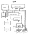
- -la figure 1 est un schéma d'ensemble du système selon l'invention,
- -la figure 2 est un organigramme illustrant les différentes étapes d'une liaison à l'aide du système selon l'invention,
- -la figure 3 est un schéma synoptique d'une borne fixe selon l'invention,
- -la figure 4 est un schéma du circuit logique d'une voie de cette borne fixe, et
- -la figure 5 est un schéma synoptique d'un combiné portatif selon l'invention.
- FIG. 1 is an overall diagram of the system according to the invention,
- FIG. 2 is a flowchart illustrating the different stages of a connection using the system according to the invention,
- FIG. 3 is a block diagram of a fixed terminal according to the invention,
- FIG. 4 is a diagram of the logic circuit of a channel of this fixed terminal, and
- FIG. 5 is a block diagram of a portable handset according to the invention.
On voit sur la figure 1 une borne fixe (1) reliée par un ensemble de lignes téléphoniques d'abonnés (2) à un central téléphonique (3). La borne fixe (1) comporte autant de voies qu'il existe de lignes (2), chaque voie se comportant vis à vis du central (3) comme un poste d'abonné. Un ensemble (4) de photodiodes et de photorécepteurs infrarouges permet d'établir une liaison (5) avec autant de combinés portatifs (6) qu'il existe de lignes téléphoniques (2) reliant le central (3) à la borne fixe (1).We see in Figure 1 a fixed terminal (1) connected by a set of subscriber telephone lines (2) to a telephone exchange (3). The fixed terminal (1) has as many channels as there are lines (2), each channel behaving towards the exchange (3) like a subscriber station. A set (4) of photodiodes and infrared photoreceptors makes it possible to establish a connection (5) with as many portable handsets (6) as there are telephone lines (2) connecting the central office (3) to the fixed terminal (1 ).
A cet effet chaque combiné portatif (6) comprend également un ensemble de photodiodes et de photorécepteurs infrarouges (7) permettant d'émettre des informations à destination de la borne (1) et de recevoir d'autres informations de cette dernière.For this purpose each portable handset (6) also comprises a set of photodiodes and infrared photoreceptors (7) making it possible to transmit information intended for the terminal (1) and to receive other information from the latter.
Bien entendu le combiné (6) comprend également au moins un clavier à touches de numérotation et de fonctions, un microphone, un haut-parleur, ainsi de préférence qu'un écran d'affichage à cristaux liquides.Of course, the handset (6) also comprises at least one keyboard with dialing and function keys, a microphone, a loudspeaker, and preferably also a liquid crystal display screen.
Enfin selon l'invention chaque combiné portatif (6) comprend un logement permettant la réception d'une carte à mémoire (8) supportant une mémoire morte programmable. Des contacts électriques appropriés dans ce logement permettent d'assurer l'interface entre les circuits décrits ci-après du combiné (6) et la mémoire portée par la carte (8).Finally according to the invention each portable handset (6) comprises a housing allowing the reception of a memory card (8) supporting a programmable read only memory. Appropriate electrical contacts in this housing make it possible to provide the interface between the circuits described below of the handset (6) and the memory carried by the card (8).
Les ensembles infrarouges (4 et 7) sont de préférence agencés de manière à permettre deux modes de fonctionnement, à savoir un mode "grand angle" dans lequel l'émission s'effectue sur environ un quart de sphère, et un mode "angle étroit" dans lequel l'émission s'effectue suivant un angle par exemple de l'ordre de 40°. Il est ainsi possible d'augmenter la distance de réception moyennant une réduction de l'angle dans lequel cette réception est possible. Du côté de la borne fixe le passage d'un mode à l'autre peut s'effectuer automatiquement en fonction de la qualité de la réception des impulsions reçues du combiné portatif.The infrared assemblies (4 and 7) are preferably arranged so as to allow two modes of operation, namely a "wide angle" mode in which the emission takes place over approximately a quarter of a sphere, and a "narrow angle mode""in which the emission is carried out at an angle for example of the order of 40 °. It is thus possible to increase the distance of reception by reducing the angle in which this reception is possible. On the side of the fixed terminal, the passage from one mode to the other can take place automatically depending on the quality of reception of the pulses received from the portable handset.
La liaison (5) consiste en un échange entre la borne fixe (1) et les combinés portatifs (6), de paquets d'impulsions infrarouges ayant une structure temporelle fixe. Cet échange est réalisé par multiplexage dans le temps, c'est-à-dire que la borne fixe (1) adresse un premier paquet d'impulsions à l'un des combinés portatifs, puis reçoit de celui-ci un paquet d'impulsions en réponse. La borne fixe adresse alors un nouveau paquet d'impulsions à un autre combiné et ainsi de suite jusqu'à ce que le cycle recommence. La durée du cycle est égale à la période d'échantillonnage de la voix réalisée dans la borne fixe pour la réception, et dans chaque combiné pour l'émission.The link (5) consists of an exchange between the fixed terminal (1) and the portable handsets (6), of infrared pulse packets having a fixed time structure. This exchange is carried out by time multiplexing, that is to say that the fixed terminal (1) sends a first packet of pulses to one of the portable handsets, then receives from it a packet of pulses. in response. The fixed terminal then sends a new packet of pulses to another handset and so on until the cycle begins again. The cycle time is equal to the sampling period of the voice performed in the fixed terminal for reception, and in each handset for transmission.
Chaque paquet d'impulsions comporte notamment :
- -une impulsion initiale de synchronisation dont la fonction est de caler le récepteur éventuel (borne fixe ou combiné portatif) pour qu'il puisse recevoir et répartir les différentes impulsions suivantes dans un système de pile;
- -une série d'impulsions de gestion indiquant le numéro de la voie utilisée de façon à assurer la confidentialité de la liaison. En effet quand un combiné portatif capte un paquet d'impulsions, il teste ces impulsions de désignation de voie de façon à savoir s'il doit prendre en compte cette émission et y répondre. Par contre tous les combinés portatifs émettent le même numéro de voie. Ainsi un combiné portatif ne peut pas répondre à un autre combiné portatif qui se trouverait à proximité et dont il capterait l'émission par erreur. De toute manière il n'y a aucun risque de voir la borne fixe commettre une erreur sur l'origine d'un paquet d'impulsions, du fait que chaque combiné portatif ne peut émettre qu'en réponse à la réception de l'impulsion de fin de paquet décrite ci-après, émise par la borne ;
- -d'autres impulsions de gestion permettant de faire passer de façon inaudible pour l'utilisateur un certain nombre d'informations telles que les informations de numérotation, et plus particulièrement les informations de taxation. Dans le sens borne/combiné, ces informations de taxation sont constituées d'un code visant à débiter la carte à mémoire au fur et à mesure de la communication. Dans le sens combiné/borne, ces informations de taxation sont constituées par le signal d'acquittement établissant que la carte à mémoire a bien été débitée en réponse à la réception du code émis par la borne;
- -des impulsions de données phoniques permettant au récepteur de reconstituer le son comme cela sera décrit ci après;
- -une impulsion de fin de paquet dont la fonction est de faire démarrer l'horloge libre de séquencement d'émission du correspondant si son paquet d'impulsions doit suivre.
- an initial synchronization pulse whose function is to calibrate the possible receiver (fixed terminal or portable handset) so that it can receive and distribute the following different pulses in a battery system;
- -a series of management pulses indicating the number of the channel used so as to ensure the confidentiality of the link. In fact, when a portable handset picks up a packet of pulses, it tests these channel designation pulses so as to know whether it must take this transmission into account and respond to it. On the other hand, all portable handsets transmit the same channel number. Thus a portable handset cannot respond to another portable handset which is nearby and whose transmission it would receive by mistake. In any case there is no risk of the fixed terminal committing an error on the origin of a pulse packet, since each portable handset can only transmit in response to reception of the pulse end of packet described below, sent by the terminal;
- other management pulses making it possible to pass inaudible to the user a certain number of information such as the dialing information, and more particularly the charging information. In the terminal / combined direction, this charging information consists of a code aimed at debiting the memory card as and when communication measurement. In the combined / terminal direction, this charging information is constituted by the acknowledgment signal establishing that the memory card has indeed been debited in response to the reception of the code transmitted by the terminal;
- pulses of phonic data allowing the receiver to reconstruct the sound as will be described below;
- -a packet end pulse whose function is to start the correspondent's free transmission sequencing clock if its pulse packet has to follow.
Afin de permettre l'installation de la borne fixe dans un milieu non protégé, on prévoit un procédé de redondance séquentielle permettant d'assurer la fiabilité de la transmission.In order to allow the installation of the fixed terminal in an unprotected environment, provision is made for a sequential redundancy process making it possible to ensure the reliability of the transmission.
A cet effet les impulsions de données phoniques de chaque paquet d'impulsions comprennent l'information codée correspondant non seulement au dernier échantillonnage, mais également aux deux échantillonnages précédents. Chaque donnée est donc transmise trois fois, chacune des valeurs transmises étant conservée en mémoire du côté du récepteur.For this purpose, the phonic data pulses of each pulse packet include the coded information corresponding not only to the last sampling, but also to the two preceding samplings. Each data item is therefore transmitted three times, each of the transmitted values being kept in memory on the receiver side.
Une logique combinatoire permet à partir de ces trois valeurs mémorisées de déterminer la valeur la plus probable qui est alors adressée au système de conversion.Combinatorial logic makes it possible from these three stored values to determine the most probable value which is then addressed to the conversion system.
Chaque donnée phonique est donc décalée dans le temps d'une valeur égale à trois fois la période d'échantillonnage du convertisseur mais cette valeur reste d'un ordre de grandeur imperceptible pour l'oreille.Each sound data is therefore shifted in time by a value equal to three times the sampling period of the converter, but this value remains of an order of magnitude imperceptible to the ear.
On décrira maintenant d'une manière générale, en référence à la figure 2, comment se déroule une communication téléphonique entre un combiné portatif (6) et un poste d'abonné connecté au réseau auquel est relié le central téléphonique (3).A general description will now be given, with reference to FIG. 2, of how a telephone communication takes place between a portable handset (6) and a subscriber station connected to the network to which the telephone exchange (3) is connected.
Le possesseur d'un combiné (6) se place tout d'abord à une distance d'une borne fixe (1) permettant d'assurer une liaison infrarouge dans de bonnes conditions. Il met ensuite en (10) son combiné en configuration de marche active, par exemple en l'ouvrant complètement si ce combiné est repliable. Le combiné se met alors en écoute en (11) pour détecter en (12) une éventuelle émission provenant de la borne fixe (1). Si aucune émission n'est détectée, le combiné émet au bout d'un certain temps en (13) quelques impulsions infrarouges destinées à exciter la borne fixe puis se remet en position d'écoute pour capter l'émission attendue.The owner of a handset (6) first places himself at a distance from a fixed terminal (1) allowing an infrared link to be provided under good conditions. He then sets his handset to (10) in active running configuration, for example by opening it completely if this handset is foldable. The handset then listens in (11) to detect in (12) a possible transmission from the fixed terminal (1). If no emission is detected, the handset transmits after a certain time in (13) a few infrared pulses intended to excite the fixed terminal then returns to the listening position to receive the expected emission.
Dès la réception d'un premier paquet d'impulsions en (12), le combiné teste en (14) les impulsions de gestion de ce paquet afin de s'assurer qu'il provient bien de la borne fixe et non pas d'un autre combiné qui serait en service à proximité.Upon receipt of a first packet of pulses in (12), the handset tests in (14) the management pulses of this packet to ensure that it comes from the fixed terminal and not from a another handset that would be in service nearby.
Après la réception du premier paquet d'impulsions de la borne fixe,le combiné se met en écoute pendant un temps correspondant à l'écart temporel entre deux voies successives de la borne fixe, pour déterminer en (15) si la voie suivante est occupée. Si un autre paquet d'impulsions survient, le combiné réitère la même action jusqu'à percevoir la présence d'un "trou" dans la succession des paquets d'impulsions.After receiving the first packet of pulses from the fixed terminal, the handset listens for a time corresponding to the time difference between two successive channels of the fixed terminal, to determine in (15) whether the next channel is occupied . If another pulse packet occurs, the handset repeats the same action until there is a "hole" in the succession of pulse packets.
Si aucun trou n'est détecté, toutes les voies de la borne fixe sont occupées.If no hole is detected, all the channels of the fixed terminal are occupied.
Si au contraire un trou est détecté le combiné émet en (16) un signal de demande de voie, synchronisé sur les signaux du paquet précédemment reçu.If, on the contrary, a hole is detected, the handset transmits at (16) a channel request signal, synchronized with the signals of the previously received packet.
Le combiné se met alors en écoute en (17) pendant une durée égale à un cycle de la borne fixe en attente de la réponse en (18) par laquelle la borne fixe indique qu'elle dispose d'une ligne libre. Cette réponse comporte une identification de la voie attribuée au combiné.The handset then listens in (17) for a period equal to one cycle of the fixed terminal awaiting the response in (18) by which the fixed terminal indicates that it has a free line. This response includes an identification of the channel allocated to the handset.
La liaison entre le combiné et la borne est alors établie en (19) et la borne transmet au combiné la tonalité d'invitation à numéroter.The connection between the handset and the terminal is then established at (19) and the terminal transmits the dialing tone to the handset.
Le possesseur du combiné compose alors en (20) le numéro de son correspondant, que la borne fixe (1) transmet au central (3) par l'intermédiaire de la ligne téléphonique (2) correspondant à la voie attribuée au combiné. La communication s'établit alors en (21) et l'échange de paquet d'impulsions se poursuit comme indiqué ci-dessus, jusqu'à la fin de transmission en (22).The owner of the handset then dials (20) the number of his correspondent, which the fixed terminal (1) transmits to the exchange (3) via the telephone line (2) corresponding to the channel allocated to the handset. The communication is then established in (21) and the exchange of pulse packets continues as indicated above, until the end of transmission in (22).
Au cours de la communication, le combiné détecte, parmi les impulsions de gestion, celles qui correspondent à une demande de débit de la carte à mémoire. Lors de leur réception, les circuits du combiné débitent une unité de taxation sur la carte et adressent à la borne fixe, dans le paquet d'impulsions suivant, un signal d'acquittement. En l'absence de ce signal, la borne fixe coupe la communication.During the communication, the handset detects, among the management pulses, those which correspond to a debit request from the memory card. When received, the handset circuits debit a charging unit on the card and send an acknowledgment signal to the fixed terminal in the next pulse packet. In the absence of this signal, the fixed terminal cuts the communication.
On décrira maintenant la borne fixe (1) en référence aux figures 3 et 4.We will now describe the fixed terminal (1) with reference to Figures 3 and 4.
Comme montré sur la figure 3 cette borne comporte une interface (30) avec les lignes (2).As shown in Figure 3 this terminal has an interface (30) with the lines (2).
C'est au niveau de cette interface (30) que s'effectue la détection des signaux de taxation provenant du central (3) par l'intermédiaire des lignes (2).It is at this interface (30) that the charging signals from the central office (3) are detected via the lines (2).
L'interface (30) est gérée par un microprocesseur (31) piloté par une horloge (32). Le microprocesseur (31) assure notamment la gestion des informations de taxation provenant de l'interface (30) de manière à les coder et à assurer leur émission vers les différents combinés utilisant la borne fixe. Le microprocesseur (31) est également agencé pour vérifier la réception des signaux d'acquittement provenant des combinés et pour couper la communication en l'absence de ces signaux.The interface (30) is managed by a microprocessor (31) controlled by a clock (32). The microprocessor (31) notably manages the charging information coming from the interface (30) so as to code them and ensure their transmission to the various handsets using the fixed terminal. The microprocessor (31) is also arranged to check the reception of the acknowledgment signals from the handsets and to cut off the communication in the absence of these signals.
La borne fixe comporte également des mémoires (33) contenant les différentes données nécessaires au fonctionnement du microprocesseur.The fixed terminal also includes memories (33) containing the various data necessary for the operation of the microprocessor.
Un circuit logique câblé (34) qui sera décrit plus en détail ci-après, est commandé par le microprocesseur (1), et assure le transfert des informations vers un bloc d'émission (35), et provenant d'un bloc de réception (36).A wired logic circuit (34) which will be described in more detail below, is controlled by the microprocessor (1), and ensures the transfer of information to a transmission block (35), and coming from a reception block (36).
Le bloc d'émission (35) assure la commande des diodes photo-émettrices infrarouges mentionnées ci-dessus, alors que le bloc de réception (36) sert d'interface entre les photo-récepteurs du bloc optique et la logique câblée (34).The transmission unit (35) controls the infrared photo-emitting diodes mentioned above, while the reception unit (36) serves as an interface between the photo-receivers of the optical unit and the wired logic (34) .
Comme représenté à la figure 4, une voie de cette logique câblée comprend essentiellement un registre à décalage de réception (40) et un registre à décalage d'émission (41). Le registre (40) est relié au bloc deAs shown in FIG. 4, one channel of this wired logic essentially comprises a reception shift register (40) and a transmission shift register (41). The register (40) is connected to the block of
redondance séquentielle (42) permettant de distinguer, lors de la réception, les impulsions de données phoniques correspondant aux trois échantillonnages précédent.sequential redundancy (42) making it possible to distinguish, upon reception, the pulses of phonic data corresponding to the three preceding samplings.
Les impulsions provenant du bloc de réception (36) sont transmises au registre de réception (40) par l'intermédiaire d'un circuit logique de validation de voie de réception (43).The pulses from the reception block (36) are transmitted to the reception register (40) via a reception channel validation logic circuit (43).
Lors de la réception d'un paquet d'impulsions par le bloc de réception (36) et de la validation de la voie par la logique (43), l'impulsion de synchronisation de ce paquet provoque le basculement d'une bascule (44) qui fait démarrer l'horloge de cadencement de réception (45) de façon à remplir le registre à décalage (40) des différentes valeurs des impulsions suivantes. Les impulsions d'horloge sont comptées dans un compteur (46) muni d'un circuit décodeur. Une logique de synchronisation (47) reliée au compteur décodeur (46) permet ainsi de se caler sur l'impulsion de fin de paquet pour arrêter l'horloge de réception (45) par la bascule (44), et préparer le démarrage d'une horloge d'émission (48).During the reception of a packet of pulses by the reception block (36) and the validation of the channel by the logic (43), the synchronization pulse of this packet causes the flip-flop (44) ) which starts the reception clock (45) so as to fill the shift register (40) with the different values of the following pulses. The clock pulses are counted in a counter (46) provided with a decoder circuit. Synchronization logic (47) connected to the decoder counter (46) thus makes it possible to lock onto the end-of-packet pulse to stop the reception clock (45) by the flip-flop (44), and prepare the start of a transmission clock (48).
Les informations de données qui se trouvent dans le registre à décalage (40) sont transmises au bloc de traitement de la redondance séquentielle (42) commandé par une logique (49). Ce bloc (42) permet de lever éventuellement un doute sur la valeur de la donnée à transférer au convertisseur numérique/analogique (50), et de ce convertisseur, à l'interface (30). Par contre les informations de gestion contenues dans le registre à décalage (40) sont transmises au microprocesseur (31) par l'intermédiaire du bus (51).The data information in the shift register (40) is transmitted to the sequential redundancy processing block (42) controlled by logic (49). This block (42) makes it possible to possibly remove a doubt about the value of the data to be transferred to the digital / analog converter (50), and from this converter, to the interface (30). On the other hand, the management information contained in the shift register (40) is transmitted to the microprocessor (31) via the bus (51).
Dès l'occurence du signal de fin de transmission délivrée par la logique de synchronisation (47), on effectue un chargement du registre à décalage d'émission (41) à partir d'une part, pour les informations de données phoniques, d'une mémoire-tampon (52) reliée à l'interface (30) par l'intermédiaire d'un convertisseur analogique/numérique (53), et d'autre part, pour les informations de gestion, d'un bus (54) relié au microprocesseur. Les impulsions de synchronisation de début et de fin de paquet sont introduites dans le registre (41) par forçage. L'horloge d'émission (48) est alors lancée par une bascule (55) et cadence la transmission des données qui sortent du registre à décalage (41) vers le bloc d'émission (35).As soon as the end of transmission signal delivered by the synchronization logic (47) occurs, the transmission shift register (41) is loaded on the one hand, for the phonic data information, of a buffer memory (52) connected to the interface (30) via an analog / digital converter (53), and on the other hand, for management information, a bus (54) connected to the microprocessor. The start and end of packet synchronization pulses are introduced into the register (41) by forcing. The transmission clock (48) is then started by a flip-flop (55) and synchronizes the transmission of the data which leaves the shift register (41) to the transmission block (35).
Un compteur (56) muni d'un décodeur permet d'arrêter l'horloge d'émission lors de la détection de l'impulsion de fin de paquet. On notera enfin que de même qu'à la réception, le registre à décalage d'émission (41) est relié au bloc d'émission (35) par l'intermédiaire d'une logique de validation d'émission (57).A counter (56) provided with a decoder makes it possible to stop the transmission clock when the end of packet pulse is detected. Finally, it will be noted that, as on reception, the transmission shift register (41) is connected to the transmission block (35) via a transmission validation logic (57).
On décrira maintenant en référence à la figure 5 l'agencement général d'un combiné (6).The general arrangement of a handset (6) will now be described with reference to FIG. 5.
Sur cette figure on a représenté en (60) le microprocesseur du combiné piloté par une horloge (61) et relié à une mémoire (62) contenant les données nécessaires à son fonctionnement.This figure shows in (60) the microprocessor of the handset controlled by a clock (61) and connected to a memory (62) containing the data necessary for its operation.
Le microprocesseur est également relié au clavier (63) du combiné et à son écran de visualisation (64).The microprocessor is also connected to the keyboard (63) of the handset and to its display screen (64).
De même que pour la borne fixe, un bloc d'émission (65) et un bloc de réception (66) sont reliés à une logique câblée (67) recevant des informations d'une part du microprocesseur (60), et d'autre part d'une interface (68) avec le micro et le haut-parleur du combiné.As for the fixed terminal, a transmission block (65) and a reception block (66) are connected to a wired logic (67) receiving information on the one hand from the microprocessor (60), and on the other part of an interface (68) with the microphone and the loudspeaker of the handset.
Enfin le microprocesseur (60) est relié à un circuit (69) d'interface avec la carte à mémoire de manière à débiter cette dernière d' unités de taxation successives lors de la réception des informations de taxation par l'intermédiaire du bloc (66) et de la logique câblée (67).Finally, the microprocessor (60) is connected to a circuit (69) for interfacing with the memory card so as to debit the latter from successive charging units when receiving charging information via the block (66 ) and wired logic (67).
Le circuit logique (67) est identique au circuit logique d'une voie de la borne fixe tel que décrit en référence à la figure 4, si ce n'est l'absence des blocs de validation (43) et (57).The logic circuit (67) is identical to the logic circuit of a channel of the fixed terminal as described with reference to FIG. 4, except for the absence of the validation blocks (43) and (57).
0n prévoit en outre la possibilité pour le possesseur d'un combiné portatif d'être appelé par l'intermédiaire d'une borne fixe prédéterminée.0n also provides the possibility for the owner of a portable handset to be called via a predetermined fixed terminal.
A cet effet il se place à proximité de cette borne et place par une commande appropriée son combiné dans une position de veille dans laquelle les circuits de réception sont alimentés. Le correspondant compose le numéro de ligne de la borne fixe. Celle-ci décroche la ligne et émet sur celle-ci une invitation à composer un code complémentaire caractéristique du combiné de son correspondant. Ce code peut par exemple être à deux chiffres, la probabilité d'avoir en présence deux combinés portatifs affectés du même numéro étant alors suffisamment faible. La borne fixe émet ensuite un paquet de signaux d'appel comprenant notamment ce code, ce qui a pour effet de faire émettre un signal sonore par le combiné concerné. Le possesseur de ce combiné met alors son appareil en position de marche de manière à prendre la communication.For this purpose it is placed near this terminal and places its handset by an appropriate command in a standby position in which the reception circuits are supplied. The correspondent dials the line number of the fixed terminal. The latter picks up the line and sends on it an invitation to dial an additional code characteristic of his correspondent's handset. This code can for example be two digits, the probability of having two portable handsets in the presence assigned the same number then being sufficiently low. The fixed terminal then transmits a packet of call signals including this code, which has the effect of causing an audible signal to be transmitted by the handset concerned. The owner of this handset then puts his device in the on position so as to take the call.
Diverses variantes et modifications peuvent bien entendu être apportées à la description qui précède sans sortir pour autant du cadre ni de l'esprit de l'invention.Various variants and modifications can of course be made to the above description without departing from the scope or the spirit of the invention.
Claims (7)
Priority Applications (1)
| Application Number | Priority Date | Filing Date | Title |
|---|---|---|---|
| AT87400189T ATE67913T1 (en) | 1986-01-28 | 1987-01-28 | TELEPHONE COMMUNICATION SYSTEM WITH PORTABLE HANDSETS. |
Applications Claiming Priority (2)
| Application Number | Priority Date | Filing Date | Title |
|---|---|---|---|
| FR8601277 | 1986-01-28 | ||
| FR8601277A FR2593656B1 (en) | 1986-01-28 | 1986-01-28 | COMPACT WIRELESS INDIVIDUAL COMMUNICATION METHOD OPERATING ON AN INFRARED DUPLEX NETWORK AND ITS IMPLEMENTING DEVICE. |
Publications (2)
| Publication Number | Publication Date |
|---|---|
| EP0236180A1 true EP0236180A1 (en) | 1987-09-09 |
| EP0236180B1 EP0236180B1 (en) | 1991-09-25 |
Family
ID=9331627
Family Applications (1)
| Application Number | Title | Priority Date | Filing Date |
|---|---|---|---|
| EP87400189A Expired - Lifetime EP0236180B1 (en) | 1986-01-28 | 1987-01-28 | Telephonic communication system with a portable hand set |
Country Status (11)
| Country | Link |
|---|---|
| US (1) | US4776000A (en) |
| EP (1) | EP0236180B1 (en) |
| JP (1) | JPS62230152A (en) |
| AT (1) | ATE67913T1 (en) |
| CA (1) | CA1263197A (en) |
| DE (1) | DE3773232D1 (en) |
| ES (1) | ES2027697T3 (en) |
| FR (1) | FR2593656B1 (en) |
| IL (1) | IL81404A0 (en) |
| MA (1) | MA20859A1 (en) |
| TN (1) | TNSN87011A1 (en) |
Cited By (6)
| Publication number | Priority date | Publication date | Assignee | Title |
|---|---|---|---|---|
| WO1989006075A1 (en) * | 1987-12-14 | 1989-06-29 | Hm Electronics, Inc. | Wireless optical communication system |
| WO1990000844A1 (en) * | 1988-07-08 | 1990-01-25 | Raoul Parienti | A system for communicating and managing private data |
| EP0492051A1 (en) * | 1990-12-10 | 1992-07-01 | Robert Bosch Gmbh | Radiotelephone network enabling communication outside the coverage zone |
| US5305132A (en) * | 1987-12-14 | 1994-04-19 | H. M. Electronics, Inc. | Optical wavelength communication system and method of using same |
| WO1997011435A2 (en) * | 1995-09-04 | 1997-03-27 | British Telecommunications Public Limited Company | Transaction support apparatus |
| US6192231B1 (en) | 1996-07-11 | 2001-02-20 | British Telecommunications Public Limited Company | Telephone apparatus |
Families Citing this family (94)
| Publication number | Priority date | Publication date | Assignee | Title |
|---|---|---|---|---|
| US5127040A (en) * | 1987-06-02 | 1992-06-30 | Motorola, Inc. | Radiotelephone telephone number down loading |
| US4856046A (en) * | 1988-04-08 | 1989-08-08 | Jerry R. Iggulden | Remote public telephone link |
| JPH02113659A (en) * | 1988-10-21 | 1990-04-25 | Asahi Tsushin Kogyo Kk | Plug-in type public telephone system |
| JPH02141167A (en) * | 1988-11-22 | 1990-05-30 | Masao Tokura | Cordless public telephone system |
| FI85787C (en) * | 1989-05-25 | 1992-05-25 | Nokia Mobira Oy | CONSTRUCTION FOER EN SAOSOM SJAELVSTAENDIG ENHET FUNGERANDE HANDTELEFON. |
| JPH03128563A (en) * | 1989-07-07 | 1991-05-31 | Toshiba Corp | Radio telephony equipment |
| SE500289C2 (en) * | 1989-08-11 | 1994-05-30 | Ericsson Telefon Ab L M | Method of monitoring telephone subscriptions in a mobile phone system |
| GB2235606B (en) * | 1989-08-24 | 1994-03-30 | Technophone Ltd | Portable telephone |
| JPH03117955A (en) * | 1989-09-30 | 1991-05-20 | Anritsu Corp | Cordless telephone set with charge processor |
| JP2661760B2 (en) * | 1990-01-20 | 1997-10-08 | 株式会社船井電機研究所 | Information transmission system |
| FR2660771B1 (en) * | 1990-04-05 | 1992-07-24 | Bernard Alain | TELEPHONE PAYMENT SYSTEM. |
| US5617474A (en) * | 1990-05-08 | 1997-04-01 | The Goeken Group Corporation | Telephone handset having a latch-receiving opening in an enlarged inlet opening of a card-receiving slot |
| WO1991018467A1 (en) * | 1990-05-22 | 1991-11-28 | Cellular Technical Services Company | Cellular phone rental system |
| US5301223A (en) * | 1990-05-22 | 1994-04-05 | Cellular Technical Services Company, Inc. | Cellular telephone system with remote programming, voice responsive registration and real time billing |
| US5241410A (en) * | 1990-06-21 | 1993-08-31 | Litephone Systems Ltd. | Enhanced infrared-connected telephone system |
| US5077790A (en) * | 1990-08-03 | 1991-12-31 | Motorola, Inc. | Secure over-the-air registration of cordless telephones |
| US5138650A (en) * | 1990-09-27 | 1992-08-11 | Motorola, Inc. | Cordless telephone with internal debit and credit memory |
| CA2105570C (en) * | 1991-03-04 | 2002-05-21 | Alan D. Wittstein | Mobile telephone, system and method |
| US5303297A (en) * | 1991-07-25 | 1994-04-12 | Motorola, Inc. | Dynamic pricing method and apparatus for communication systems |
| US5265155A (en) * | 1991-07-31 | 1993-11-23 | Integrated Communications, Ltd. | Method and apparatus for prepayment of telecommunication connections in a telecommunication switching network |
| JP2689785B2 (en) * | 1991-09-30 | 1997-12-10 | 日本電気株式会社 | Small portable radio |
| AU3238793A (en) * | 1991-12-12 | 1993-07-19 | Cellular Technical Services Company, Inc. | Real-time information system for cellular telephones |
| US5463671A (en) * | 1992-11-16 | 1995-10-31 | Csir | Telecommunications network having a distributed network of decentralized local stations |
| JPH07118750B2 (en) * | 1993-03-01 | 1995-12-18 | 日本電気株式会社 | Satellite communication billing method |
| TW249877B (en) * | 1993-11-23 | 1995-06-21 | Bellsouth Int Inc | |
| US5517549A (en) * | 1993-12-03 | 1996-05-14 | Telefonaktiebolaget L M Ericcson | Call logging in cellular subscriber stations |
| JPH07298340A (en) * | 1994-03-02 | 1995-11-10 | Fujitsu Ltd | Mobile communication system and mobile station |
| JP3293305B2 (en) * | 1994-03-07 | 2002-06-17 | 松下電器産業株式会社 | Digital radio telephone equipment |
| WO1995028062A2 (en) * | 1994-04-07 | 1995-10-19 | Nokia Telecommunications Oy | A removable subscriber identification module for a mobile radio terminal and a call control method |
| JP2998889B2 (en) | 1994-04-28 | 2000-01-17 | キヤノン株式会社 | Wireless communication system |
| US5511114A (en) * | 1994-06-06 | 1996-04-23 | Call Processing, Inc. | Telephone pre-paid calling card system and method |
| US5577109A (en) * | 1994-06-06 | 1996-11-19 | Call Processing, Inc. | Pre-paid card system and method |
| AU3326695A (en) * | 1994-08-15 | 1996-03-07 | Ken Bailey | Cellular telephone credit card billing system |
| US5570416A (en) * | 1994-08-30 | 1996-10-29 | Comtel Debit Card Limited, L.L.C. | Call center management system |
| FI100083B (en) * | 1994-09-20 | 1997-09-15 | Nokia Mobile Phones Ltd | The terminal |
| US5734977A (en) * | 1994-11-10 | 1998-03-31 | Telefonaktiebolaget Lm Ericsson | Fraud detection in radio communications network |
| US5826185A (en) * | 1994-11-16 | 1998-10-20 | Banana Cellular, Inc. | Cellular phone system wherein the air time use is predetermined |
| NZ513721A (en) * | 1994-12-02 | 2001-09-28 | British Telecomm | Communications apparatus and signal |
| US5722067A (en) * | 1994-12-23 | 1998-02-24 | Freedom Wireless, Inc. | Security cellular telecommunications system |
| US5854975A (en) * | 1994-12-23 | 1998-12-29 | Freedom Wireless, Inc. | Prepaid security cellular telecommunications system |
| US5983091A (en) | 1995-01-05 | 1999-11-09 | Omni Telecommunications, Inc. | Portable communication unit with discrete allocable blocks of airtime |
| US5577100A (en) * | 1995-01-30 | 1996-11-19 | Telemac Cellular Corporation | Mobile phone with internal accounting |
| SE9501051L (en) * | 1995-03-23 | 1996-09-24 | Telia Ab | Telephone system with person / subscriber bound identification |
| DE19515197A1 (en) * | 1995-04-25 | 1996-10-31 | Siemens Ag | System for locally flexible telecommunications |
| FI106496B (en) * | 1995-06-15 | 2001-02-15 | Nokia Mobile Phones Ltd | Multilevel home pricing for cellular cellular networks |
| US5751789A (en) * | 1995-11-13 | 1998-05-12 | Bell Atlantic Network Services, Inc. | SNID with wireless backup |
| US5778313A (en) | 1995-12-08 | 1998-07-07 | Cellexis International, Inc. | Pre-paid cellular telephone system |
| US6112077A (en) | 1995-12-29 | 2000-08-29 | Stx Corporation | Nonreusable cellular telephone |
| US5815807A (en) * | 1996-01-31 | 1998-09-29 | Motorola, Inc. | Disposable wireless communication device adapted to prevent fraud |
| FR2745970B1 (en) * | 1996-03-07 | 1998-08-07 | France Telecom | PREPAYMENT METHOD FOR CONSUMPTION OF TELEPHONE COMMUNICATIONS |
| KR0174485B1 (en) * | 1996-04-30 | 1999-04-01 | 김광호 | Infrared wireless communication system using telephone line and method thereof |
| US5940767A (en) * | 1996-05-07 | 1999-08-17 | Ericsson, Inc. | Intelligent docking station for use with a portable wireless receiver to provide expanded short message services |
| US5946614A (en) * | 1996-06-13 | 1999-08-31 | Qualcomm Incorporated | Payphone metering in a wireless telephone system |
| US6188752B1 (en) * | 1996-11-12 | 2001-02-13 | Telefonaktiebolaget Lm Ericsson (Publ) | Method and apparatus for providing prepaid telecommunications services |
| US5960416A (en) * | 1997-02-27 | 1999-09-28 | Block; Robert S. | Real time subscriber billing at a subscriber location in an unstructured communication network |
| US6377938B1 (en) * | 1997-02-27 | 2002-04-23 | Real-Time Billing, Inc. | Real time subscriber billing system and method |
| US6061580A (en) * | 1997-02-28 | 2000-05-09 | Randice-Lisa Altschul | Disposable wireless telephone and method for call-out only |
| US6405031B1 (en) | 1997-02-28 | 2002-06-11 | Dieceland Technologies Corp. | Wireless telephone system, telephone and method |
| US5845218A (en) * | 1997-02-28 | 1998-12-01 | Altschul; Randice-Lisa | Disposable wireless telephone and method |
| US5965848A (en) * | 1997-07-22 | 1999-10-12 | Randice-Lisa Altschul | Disposable portable electronic devices and method of making |
| US5983094A (en) * | 1997-10-27 | 1999-11-09 | Randice-Lisa Altschul | Wireless telephone with credited airtime and method |
| US6070067A (en) * | 1997-10-31 | 2000-05-30 | Telefonaktiebolaget Lm Ericsson | Prepayment method utilizing credit information stored in mobile terminals for accessing wireless telecommunication networks |
| US5946380A (en) * | 1997-11-06 | 1999-08-31 | At&T Corp. | Communications system and method with call expenditure control |
| US7145989B1 (en) | 1998-07-27 | 2006-12-05 | Mci, Inc. | Pre-paid telephone calling card having an associated pre-recorded personal greeting |
| US6704563B1 (en) | 1998-08-11 | 2004-03-09 | Boston Communications Group, Inc. | Systems and methods for prerating costs for a communication event |
| AU9119998A (en) * | 1998-08-26 | 2000-03-21 | Harris Corporation | Method of time-to-talk calculation |
| US6836651B2 (en) | 1999-06-21 | 2004-12-28 | Telespree Communications | Portable cellular phone system having remote voice recognition |
| US7274928B2 (en) * | 1998-10-02 | 2007-09-25 | Telespree Communications | Portable cellular phone system having automatic initialization |
| US7187928B1 (en) | 1998-11-24 | 2007-03-06 | Boston Communications Group, Inc. | Call delivery systems for roaming prepaid subscribers |
| US6404869B1 (en) | 1999-01-12 | 2002-06-11 | Worldcom, Inc. | Preferred billing rate pre-paid telephone calling card |
| SE525728C2 (en) * | 1999-01-27 | 2005-04-12 | Ericsson Telefon Ab L M | Portable telecommunications device for multiple audio accessories |
| WO2000056051A1 (en) * | 1999-03-12 | 2000-09-21 | Mti, Inc. | Cellular telephone with reduced radiation exposure |
| US7180990B1 (en) | 1999-05-27 | 2007-02-20 | Mci, Llc | Prepaid telephone calling card with message recording capability |
| US6490458B1 (en) * | 1999-06-16 | 2002-12-03 | Verizon Laboratories Inc. | Portable phone bank |
| US7092501B2 (en) | 1999-10-12 | 2006-08-15 | Sbc Properties, L.P. | Method and apparatus for providing prepaid local telephone services |
| EP1266321A4 (en) | 2000-02-25 | 2003-05-21 | Telecomm Systems Inc | Prepaid short messaging |
| US7110773B1 (en) | 2000-04-11 | 2006-09-19 | Telecommunication Systems, Inc. | Mobile activity status tracker |
| US7640031B2 (en) | 2006-06-22 | 2009-12-29 | Telecommunication Systems, Inc. | Mobile originated interactive menus via short messaging services |
| US6658260B2 (en) | 2001-09-05 | 2003-12-02 | Telecommunication Systems, Inc. | Inter-carrier short messaging service providing phone number only experience |
| ES2187289B1 (en) * | 2001-10-02 | 2004-10-16 | Consulting, Comunicacio I Disseny, S.L. | MOBILE PHONE OF PERSONAL COMMUNICATION. |
| US7853272B2 (en) | 2001-12-21 | 2010-12-14 | Telecommunication Systems, Inc. | Wireless network tour guide |
| US8046581B2 (en) | 2002-03-04 | 2011-10-25 | Telespree Communications | Method and apparatus for secure immediate wireless access in a telecommunications network |
| US7197301B2 (en) * | 2002-03-04 | 2007-03-27 | Telespree Communications | Method and apparatus for secure immediate wireless access in a telecommunications network |
| AU2003283971A1 (en) * | 2002-09-30 | 2004-04-23 | Simple Products Inc. | Multiple piece wireless phone |
| DE10343458A1 (en) * | 2003-09-19 | 2005-05-12 | Thomson Brandt Gmbh | Method for processing data packets received via a first interface and device for carrying out the method |
| US7991411B2 (en) | 2004-05-06 | 2011-08-02 | Telecommunication Systems, Inc. | Method to qualify multimedia message content to enable use of a single internet address domain to send messages to both short message service centers and multimedia message service centers |
| US8195205B2 (en) | 2004-05-06 | 2012-06-05 | Telecommunication Systems, Inc. | Gateway application to support use of a single internet address domain for routing messages to multiple multimedia message service centers |
| US7430425B2 (en) | 2005-05-17 | 2008-09-30 | Telecommunication Systems, Inc. | Inter-carrier digital message with user data payload service providing phone number only experience |
| US7548158B2 (en) | 2005-08-08 | 2009-06-16 | Telecommunication Systems, Inc. | First responder wireless emergency alerting with automatic callback and location triggering |
| US8954028B2 (en) * | 2008-09-25 | 2015-02-10 | Telecommunication Systems, Inc. | Geo-redundant and high reliability commercial mobile alert system (CMAS) |
| US8712453B2 (en) | 2008-12-23 | 2014-04-29 | Telecommunication Systems, Inc. | Login security with short messaging |
| CA2825289A1 (en) | 2010-12-13 | 2012-06-21 | Telecommunication Systems, Inc. | Location services gateway server |
| US9408047B2 (en) | 2013-10-10 | 2016-08-02 | Telecommunication Systems, Inc. | Read acknowledgement interoperability for text messaging and IP messaging |
| USD905059S1 (en) | 2018-07-25 | 2020-12-15 | Square, Inc. | Card reader device |
Citations (2)
| Publication number | Priority date | Publication date | Assignee | Title |
|---|---|---|---|---|
| DE2947164A1 (en) * | 1978-11-23 | 1980-06-04 | Plessey Handel Investment Ag | TELECOMMUNICATION SYSTEM WITH PORTABLE TELECOMMUNICATION UNITS |
| EP0115240A1 (en) * | 1982-12-29 | 1984-08-08 | Michel Grandmougin | Telephone set with a bidirectional infrared link between handset and fixed module connected to a subscriber's line |
Family Cites Families (7)
| Publication number | Priority date | Publication date | Assignee | Title |
|---|---|---|---|---|
| US4275385A (en) * | 1979-08-13 | 1981-06-23 | Bell Telephone Laboratories, Incorporated | Infrared personnel locator system |
| EP0076255A1 (en) * | 1981-04-07 | 1983-04-13 | BENTON, William M. | Transaction verification system using optical data communication link |
| US4439636A (en) * | 1982-03-09 | 1984-03-27 | Martha Newkirk | Credit card actuated telecommunication access network |
| US4456793A (en) * | 1982-06-09 | 1984-06-26 | Bell Telephone Laboratories, Incorporated | Cordless telephone system |
| JPS59174972A (en) * | 1983-03-24 | 1984-10-03 | Omron Tateisi Electronics Co | Card authenticating machine |
| US4640986A (en) * | 1983-09-16 | 1987-02-03 | Nec Corporation | Mobile radio communication system |
| US4650981A (en) * | 1984-01-26 | 1987-03-17 | Foletta Wayne S | Credit card with active electronics |
-
1986
- 1986-01-28 FR FR8601277A patent/FR2593656B1/en not_active Expired - Fee Related
-
1987
- 1987-01-26 MA MA21093A patent/MA20859A1/en unknown
- 1987-01-27 IL IL81404A patent/IL81404A0/en unknown
- 1987-01-28 DE DE8787400189T patent/DE3773232D1/en not_active Expired - Lifetime
- 1987-01-28 EP EP87400189A patent/EP0236180B1/en not_active Expired - Lifetime
- 1987-01-28 AT AT87400189T patent/ATE67913T1/en not_active IP Right Cessation
- 1987-01-28 US US07/007,613 patent/US4776000A/en not_active Expired - Fee Related
- 1987-01-28 TN TNTNSN87011A patent/TNSN87011A1/en unknown
- 1987-01-28 CA CA000528370A patent/CA1263197A/en not_active Expired
- 1987-01-28 JP JP62018138A patent/JPS62230152A/en active Pending
- 1987-01-28 ES ES198787400189T patent/ES2027697T3/en not_active Expired - Lifetime
Patent Citations (2)
| Publication number | Priority date | Publication date | Assignee | Title |
|---|---|---|---|---|
| DE2947164A1 (en) * | 1978-11-23 | 1980-06-04 | Plessey Handel Investment Ag | TELECOMMUNICATION SYSTEM WITH PORTABLE TELECOMMUNICATION UNITS |
| EP0115240A1 (en) * | 1982-12-29 | 1984-08-08 | Michel Grandmougin | Telephone set with a bidirectional infrared link between handset and fixed module connected to a subscriber's line |
Cited By (11)
| Publication number | Priority date | Publication date | Assignee | Title |
|---|---|---|---|---|
| WO1989006075A1 (en) * | 1987-12-14 | 1989-06-29 | Hm Electronics, Inc. | Wireless optical communication system |
| US4882770A (en) * | 1987-12-14 | 1989-11-21 | H. M. Electronics, Inc. | Wireless optical communication system |
| US5305132A (en) * | 1987-12-14 | 1994-04-19 | H. M. Electronics, Inc. | Optical wavelength communication system and method of using same |
| WO1990000844A1 (en) * | 1988-07-08 | 1990-01-25 | Raoul Parienti | A system for communicating and managing private data |
| EP0492051A1 (en) * | 1990-12-10 | 1992-07-01 | Robert Bosch Gmbh | Radiotelephone network enabling communication outside the coverage zone |
| WO1997011435A2 (en) * | 1995-09-04 | 1997-03-27 | British Telecommunications Public Limited Company | Transaction support apparatus |
| WO1997011435A3 (en) * | 1995-09-04 | 1997-07-03 | British Telecomm | Transaction support apparatus |
| US6108632A (en) * | 1995-09-04 | 2000-08-22 | British Telecommunications Public Limited Company | Transaction support apparatus |
| EP1515530A2 (en) * | 1995-09-04 | 2005-03-16 | BRITISH TELECOMMUNICATIONS public limited company | Telephone handset for transaction support apparatus |
| EP1515530A3 (en) * | 1995-09-04 | 2005-04-27 | BRITISH TELECOMMUNICATIONS public limited company | Telephone handset for transaction support apparatus |
| US6192231B1 (en) | 1996-07-11 | 2001-02-20 | British Telecommunications Public Limited Company | Telephone apparatus |
Also Published As
| Publication number | Publication date |
|---|---|
| IL81404A0 (en) | 1987-08-31 |
| CA1263197A (en) | 1989-11-21 |
| ES2027697T3 (en) | 1992-06-16 |
| FR2593656A1 (en) | 1987-07-31 |
| EP0236180B1 (en) | 1991-09-25 |
| MA20859A1 (en) | 1987-10-01 |
| FR2593656B1 (en) | 1994-04-29 |
| TNSN87011A1 (en) | 1990-01-01 |
| JPS62230152A (en) | 1987-10-08 |
| ATE67913T1 (en) | 1991-10-15 |
| US4776000A (en) | 1988-10-04 |
| DE3773232D1 (en) | 1991-10-31 |
Similar Documents
| Publication | Publication Date | Title |
|---|---|---|
| EP0236180B1 (en) | Telephonic communication system with a portable hand set | |
| EP0460486B1 (en) | Method of centralized maintainance for a cordless telephone network | |
| EP0115240B1 (en) | Telephone set with a bidirectional infrared link between handset and fixed module connected to a subscriber's line | |
| EP0335768B1 (en) | Pre-payment information transmission system | |
| EP1180301B1 (en) | Local combined telephone and alarm system | |
| EP0004497B1 (en) | Apparatus for analysing the traffic of public telephones and remote supervision installation for analysing the traffic of public telephones served by a plurality of telephone exchanges | |
| EP0383660A1 (en) | Rate reservation in an asynchronous packet network | |
| FR2466921A1 (en) | APPARATUS FOR ASSIGNING AND SELECTING DATA TRANSMISSION CHANNEL PARTS | |
| EP0120495A1 (en) | Device for coded data exchange between stations | |
| EP0849964A1 (en) | Method and system for centralized calling to access a service, especially centralized calling for taxis | |
| EP1636975B1 (en) | Terminal and server for the synchronisation of contact data | |
| EP0082054A1 (en) | Method of synchronising transceiver sets of a frequency-hopping network, and set for carrying out this method | |
| FR2796238A1 (en) | PUBLIC TERMINAL FOR ACCESS TO A COMPUTER NETWORK | |
| EP0924581A1 (en) | Cordless phone and timer management method | |
| FR2640449A1 (en) | COMMUNICATION METHOD AND SYSTEMS WITH INFORMATION ENCRYPTION | |
| EP0018617A1 (en) | System for exchanging coded messages between stations | |
| EP0018859A1 (en) | Ringing control device | |
| FR2641149A1 (en) | ||
| FR2662321A1 (en) | RADIO COMMUNICATION DEVICE AND AUXILIARY APPARATUS THEREFOR. | |
| EP0018875A1 (en) | Automatic telephone-call generators | |
| FR2681207A1 (en) | PORTABLE TELEPHONE WITH INFORMATION STORAGE. | |
| EP1277362A1 (en) | Installation and method for data exchange between telephones and service providers | |
| FR2624679A1 (en) | Electronic payment system | |
| EP0785693A1 (en) | Protocol for local routing of incoming calls from the public switched telephone network to a cellular network | |
| FR2626125A1 (en) | Card-based apartment telephone communication system |
Legal Events
| Date | Code | Title | Description |
|---|---|---|---|
| PUAI | Public reference made under article 153(3) epc to a published international application that has entered the european phase |
Free format text: ORIGINAL CODE: 0009012 |
|
| AK | Designated contracting states |
Kind code of ref document: A1 Designated state(s): AT BE CH DE ES FR GB GR IT LI LU NL SE |
|
| 17P | Request for examination filed |
Effective date: 19880302 |
|
| 17Q | First examination report despatched |
Effective date: 19900814 |
|
| GRAA | (expected) grant |
Free format text: ORIGINAL CODE: 0009210 |
|
| AK | Designated contracting states |
Kind code of ref document: B1 Designated state(s): AT BE CH DE ES FR GB GR IT LI LU NL SE |
|
| PG25 | Lapsed in a contracting state [announced via postgrant information from national office to epo] |
Ref country code: SE Effective date: 19910925 Ref country code: GR Free format text: LAPSE BECAUSE OF FAILURE TO SUBMIT A TRANSLATION OF THE DESCRIPTION OR TO PAY THE FEE WITHIN THE PRESCRIBED TIME-LIMIT Effective date: 19910925 Ref country code: AT Effective date: 19910925 |
|
| REF | Corresponds to: |
Ref document number: 67913 Country of ref document: AT Date of ref document: 19911015 Kind code of ref document: T |
|
| REF | Corresponds to: |
Ref document number: 3773232 Country of ref document: DE Date of ref document: 19911031 |
|
| ITF | It: translation for a ep patent filed |
Owner name: INTERPATENT ST.TECN. BREV. |
|
| PG25 | Lapsed in a contracting state [announced via postgrant information from national office to epo] |
Ref country code: LU Free format text: LAPSE BECAUSE OF NON-PAYMENT OF DUE FEES Effective date: 19920131 Ref country code: LI Effective date: 19920131 Ref country code: CH Effective date: 19920131 |
|
| GBT | Gb: translation of ep patent filed (gb section 77(6)(a)/1977) | ||
| REG | Reference to a national code |
Ref country code: ES Ref legal event code: FG2A Ref document number: 2027697 Country of ref document: ES Kind code of ref document: T3 |
|
| PGFP | Annual fee paid to national office [announced via postgrant information from national office to epo] |
Ref country code: GB Payment date: 19920722 Year of fee payment: 6 |
|
| PGFP | Annual fee paid to national office [announced via postgrant information from national office to epo] |
Ref country code: BE Payment date: 19920723 Year of fee payment: 6 Ref country code: FR Payment date: 19920723 Year of fee payment: 6 |
|
| PGFP | Annual fee paid to national office [announced via postgrant information from national office to epo] |
Ref country code: DE Payment date: 19920728 Year of fee payment: 6 Ref country code: ES Payment date: 19920728 Year of fee payment: 6 |
|
| PLBE | No opposition filed within time limit |
Free format text: ORIGINAL CODE: 0009261 |
|
| STAA | Information on the status of an ep patent application or granted ep patent |
Free format text: STATUS: NO OPPOSITION FILED WITHIN TIME LIMIT |
|
| PG25 | Lapsed in a contracting state [announced via postgrant information from national office to epo] |
Ref country code: NL Effective date: 19920801 |
|
| 26N | No opposition filed | ||
| NLV4 | Nl: lapsed or anulled due to non-payment of the annual fee | ||
| REG | Reference to a national code |
Ref country code: CH Ref legal event code: PL |
|
| PG25 | Lapsed in a contracting state [announced via postgrant information from national office to epo] |
Ref country code: GB Effective date: 19930128 |
|
| PG25 | Lapsed in a contracting state [announced via postgrant information from national office to epo] |
Ref country code: ES Free format text: LAPSE BECAUSE OF NON-PAYMENT OF DUE FEES Effective date: 19930129 |
|
| PG25 | Lapsed in a contracting state [announced via postgrant information from national office to epo] |
Ref country code: BE Effective date: 19930131 |
|
| BERE | Be: lapsed |
Owner name: PARIENTI RAOUL Effective date: 19930131 |
|
| GBPC | Gb: european patent ceased through non-payment of renewal fee |
Effective date: 19930128 |
|
| PG25 | Lapsed in a contracting state [announced via postgrant information from national office to epo] |
Ref country code: FR Effective date: 19930930 |
|
| PG25 | Lapsed in a contracting state [announced via postgrant information from national office to epo] |
Ref country code: DE Effective date: 19931001 |
|
| REG | Reference to a national code |
Ref country code: FR Ref legal event code: ST |
|
| REG | Reference to a national code |
Ref country code: ES Ref legal event code: FD2A Effective date: 19990201 |
|
| PG25 | Lapsed in a contracting state [announced via postgrant information from national office to epo] |
Ref country code: IT Free format text: LAPSE BECAUSE OF NON-PAYMENT OF DUE FEES;WARNING: LAPSES OF ITALIAN PATENTS WITH EFFECTIVE DATE BEFORE 2007 MAY HAVE OCCURRED AT ANY TIME BEFORE 2007. THE CORRECT EFFECTIVE DATE MAY BE DIFFERENT FROM THE ONE RECORDED. Effective date: 20050128 |